US8643164B2 - Package-on-package technology for fan-out wafer-level packaging - Google Patents
Package-on-package technology for fan-out wafer-level packaging Download PDFInfo
- Publication number
- US8643164B2 US8643164B2 US12/512,313 US51231309A US8643164B2 US 8643164 B2 US8643164 B2 US 8643164B2 US 51231309 A US51231309 A US 51231309A US 8643164 B2 US8643164 B2 US 8643164B2
- Authority
- US
- United States
- Prior art keywords
- electrically conductive
- integrated circuit
- die
- package
- insulating material
- Prior art date
- Legal status (The legal status is an assumption and is not a legal conclusion. Google has not performed a legal analysis and makes no representation as to the accuracy of the status listed.)
- Active, expires
Links
Images


Classifications
-
- H—ELECTRICITY
- H01—ELECTRIC ELEMENTS
- H01L—SEMICONDUCTOR DEVICES NOT COVERED BY CLASS H10
- H01L23/00—Details of semiconductor or other solid state devices
- H01L23/52—Arrangements for conducting electric current within the device in operation from one component to another, i.e. interconnections, e.g. wires, lead frames
- H01L23/538—Arrangements for conducting electric current within the device in operation from one component to another, i.e. interconnections, e.g. wires, lead frames the interconnection structure between a plurality of semiconductor chips being formed on, or in, insulating substrates
- H01L23/5389—Arrangements for conducting electric current within the device in operation from one component to another, i.e. interconnections, e.g. wires, lead frames the interconnection structure between a plurality of semiconductor chips being formed on, or in, insulating substrates the chips being integrally enclosed by the interconnect and support structures
-
- H—ELECTRICITY
- H01—ELECTRIC ELEMENTS
- H01L—SEMICONDUCTOR DEVICES NOT COVERED BY CLASS H10
- H01L24/00—Arrangements for connecting or disconnecting semiconductor or solid-state bodies; Methods or apparatus related thereto
- H01L24/01—Means for bonding being attached to, or being formed on, the surface to be connected, e.g. chip-to-package, die-attach, "first-level" interconnects; Manufacturing methods related thereto
- H01L24/18—High density interconnect [HDI] connectors; Manufacturing methods related thereto
- H01L24/19—Manufacturing methods of high density interconnect preforms
-
- H—ELECTRICITY
- H01—ELECTRIC ELEMENTS
- H01L—SEMICONDUCTOR DEVICES NOT COVERED BY CLASS H10
- H01L24/00—Arrangements for connecting or disconnecting semiconductor or solid-state bodies; Methods or apparatus related thereto
- H01L24/93—Batch processes
- H01L24/95—Batch processes at chip-level, i.e. with connecting carried out on a plurality of singulated devices, i.e. on diced chips
- H01L24/97—Batch processes at chip-level, i.e. with connecting carried out on a plurality of singulated devices, i.e. on diced chips the devices being connected to a common substrate, e.g. interposer, said common substrate being separable into individual assemblies after connecting
-
- H—ELECTRICITY
- H01—ELECTRIC ELEMENTS
- H01L—SEMICONDUCTOR DEVICES NOT COVERED BY CLASS H10
- H01L25/00—Assemblies consisting of a plurality of individual semiconductor or other solid state devices ; Multistep manufacturing processes thereof
- H01L25/03—Assemblies consisting of a plurality of individual semiconductor or other solid state devices ; Multistep manufacturing processes thereof all the devices being of a type provided for in the same subgroup of groups H01L27/00 - H01L33/00, or in a single subclass of H10K, H10N, e.g. assemblies of rectifier diodes
- H01L25/10—Assemblies consisting of a plurality of individual semiconductor or other solid state devices ; Multistep manufacturing processes thereof all the devices being of a type provided for in the same subgroup of groups H01L27/00 - H01L33/00, or in a single subclass of H10K, H10N, e.g. assemblies of rectifier diodes the devices having separate containers
- H01L25/105—Assemblies consisting of a plurality of individual semiconductor or other solid state devices ; Multistep manufacturing processes thereof all the devices being of a type provided for in the same subgroup of groups H01L27/00 - H01L33/00, or in a single subclass of H10K, H10N, e.g. assemblies of rectifier diodes the devices having separate containers the devices being of a type provided for in group H01L27/00
-
- H—ELECTRICITY
- H01—ELECTRIC ELEMENTS
- H01L—SEMICONDUCTOR DEVICES NOT COVERED BY CLASS H10
- H01L25/00—Assemblies consisting of a plurality of individual semiconductor or other solid state devices ; Multistep manufacturing processes thereof
- H01L25/50—Multistep manufacturing processes of assemblies consisting of devices, each device being of a type provided for in group H01L27/00 or H01L29/00
-
- H—ELECTRICITY
- H01—ELECTRIC ELEMENTS
- H01L—SEMICONDUCTOR DEVICES NOT COVERED BY CLASS H10
- H01L2224/00—Indexing scheme for arrangements for connecting or disconnecting semiconductor or solid-state bodies and methods related thereto as covered by H01L24/00
- H01L2224/01—Means for bonding being attached to, or being formed on, the surface to be connected, e.g. chip-to-package, die-attach, "first-level" interconnects; Manufacturing methods related thereto
- H01L2224/02—Bonding areas; Manufacturing methods related thereto
- H01L2224/04—Structure, shape, material or disposition of the bonding areas prior to the connecting process
- H01L2224/04105—Bonding areas formed on an encapsulation of the semiconductor or solid-state body, e.g. bonding areas on chip-scale packages
-
- H—ELECTRICITY
- H01—ELECTRIC ELEMENTS
- H01L—SEMICONDUCTOR DEVICES NOT COVERED BY CLASS H10
- H01L2224/00—Indexing scheme for arrangements for connecting or disconnecting semiconductor or solid-state bodies and methods related thereto as covered by H01L24/00
- H01L2224/01—Means for bonding being attached to, or being formed on, the surface to be connected, e.g. chip-to-package, die-attach, "first-level" interconnects; Manufacturing methods related thereto
- H01L2224/10—Bump connectors; Manufacturing methods related thereto
- H01L2224/12—Structure, shape, material or disposition of the bump connectors prior to the connecting process
- H01L2224/12105—Bump connectors formed on an encapsulation of the semiconductor or solid-state body, e.g. bumps on chip-scale packages
-
- H—ELECTRICITY
- H01—ELECTRIC ELEMENTS
- H01L—SEMICONDUCTOR DEVICES NOT COVERED BY CLASS H10
- H01L2224/00—Indexing scheme for arrangements for connecting or disconnecting semiconductor or solid-state bodies and methods related thereto as covered by H01L24/00
- H01L2224/01—Means for bonding being attached to, or being formed on, the surface to be connected, e.g. chip-to-package, die-attach, "first-level" interconnects; Manufacturing methods related thereto
- H01L2224/18—High density interconnect [HDI] connectors; Manufacturing methods related thereto
- H01L2224/20—Structure, shape, material or disposition of high density interconnect preforms
-
- H—ELECTRICITY
- H01—ELECTRIC ELEMENTS
- H01L—SEMICONDUCTOR DEVICES NOT COVERED BY CLASS H10
- H01L2224/00—Indexing scheme for arrangements for connecting or disconnecting semiconductor or solid-state bodies and methods related thereto as covered by H01L24/00
- H01L2224/01—Means for bonding being attached to, or being formed on, the surface to be connected, e.g. chip-to-package, die-attach, "first-level" interconnects; Manufacturing methods related thereto
- H01L2224/26—Layer connectors, e.g. plate connectors, solder or adhesive layers; Manufacturing methods related thereto
- H01L2224/28—Structure, shape, material or disposition of the layer connectors prior to the connecting process
- H01L2224/29—Structure, shape, material or disposition of the layer connectors prior to the connecting process of an individual layer connector
- H01L2224/29001—Core members of the layer connector
- H01L2224/29099—Material
- H01L2224/2919—Material with a principal constituent of the material being a polymer, e.g. polyester, phenolic based polymer, epoxy
-
- H—ELECTRICITY
- H01—ELECTRIC ELEMENTS
- H01L—SEMICONDUCTOR DEVICES NOT COVERED BY CLASS H10
- H01L2224/00—Indexing scheme for arrangements for connecting or disconnecting semiconductor or solid-state bodies and methods related thereto as covered by H01L24/00
- H01L2224/01—Means for bonding being attached to, or being formed on, the surface to be connected, e.g. chip-to-package, die-attach, "first-level" interconnects; Manufacturing methods related thereto
- H01L2224/26—Layer connectors, e.g. plate connectors, solder or adhesive layers; Manufacturing methods related thereto
- H01L2224/31—Structure, shape, material or disposition of the layer connectors after the connecting process
- H01L2224/32—Structure, shape, material or disposition of the layer connectors after the connecting process of an individual layer connector
- H01L2224/321—Disposition
- H01L2224/32135—Disposition the layer connector connecting between different semiconductor or solid-state bodies, i.e. chip-to-chip
- H01L2224/32145—Disposition the layer connector connecting between different semiconductor or solid-state bodies, i.e. chip-to-chip the bodies being stacked
-
- H—ELECTRICITY
- H01—ELECTRIC ELEMENTS
- H01L—SEMICONDUCTOR DEVICES NOT COVERED BY CLASS H10
- H01L2224/00—Indexing scheme for arrangements for connecting or disconnecting semiconductor or solid-state bodies and methods related thereto as covered by H01L24/00
- H01L2224/01—Means for bonding being attached to, or being formed on, the surface to be connected, e.g. chip-to-package, die-attach, "first-level" interconnects; Manufacturing methods related thereto
- H01L2224/26—Layer connectors, e.g. plate connectors, solder or adhesive layers; Manufacturing methods related thereto
- H01L2224/31—Structure, shape, material or disposition of the layer connectors after the connecting process
- H01L2224/32—Structure, shape, material or disposition of the layer connectors after the connecting process of an individual layer connector
- H01L2224/321—Disposition
- H01L2224/32151—Disposition the layer connector connecting between a semiconductor or solid-state body and an item not being a semiconductor or solid-state body, e.g. chip-to-substrate, chip-to-passive
- H01L2224/32221—Disposition the layer connector connecting between a semiconductor or solid-state body and an item not being a semiconductor or solid-state body, e.g. chip-to-substrate, chip-to-passive the body and the item being stacked
- H01L2224/32225—Disposition the layer connector connecting between a semiconductor or solid-state body and an item not being a semiconductor or solid-state body, e.g. chip-to-substrate, chip-to-passive the body and the item being stacked the item being non-metallic, e.g. insulating substrate with or without metallisation
-
- H—ELECTRICITY
- H01—ELECTRIC ELEMENTS
- H01L—SEMICONDUCTOR DEVICES NOT COVERED BY CLASS H10
- H01L2224/00—Indexing scheme for arrangements for connecting or disconnecting semiconductor or solid-state bodies and methods related thereto as covered by H01L24/00
- H01L2224/01—Means for bonding being attached to, or being formed on, the surface to be connected, e.g. chip-to-package, die-attach, "first-level" interconnects; Manufacturing methods related thereto
- H01L2224/42—Wire connectors; Manufacturing methods related thereto
- H01L2224/47—Structure, shape, material or disposition of the wire connectors after the connecting process
- H01L2224/48—Structure, shape, material or disposition of the wire connectors after the connecting process of an individual wire connector
- H01L2224/4805—Shape
- H01L2224/4809—Loop shape
- H01L2224/48091—Arched
-
- H—ELECTRICITY
- H01—ELECTRIC ELEMENTS
- H01L—SEMICONDUCTOR DEVICES NOT COVERED BY CLASS H10
- H01L2224/00—Indexing scheme for arrangements for connecting or disconnecting semiconductor or solid-state bodies and methods related thereto as covered by H01L24/00
- H01L2224/01—Means for bonding being attached to, or being formed on, the surface to be connected, e.g. chip-to-package, die-attach, "first-level" interconnects; Manufacturing methods related thereto
- H01L2224/42—Wire connectors; Manufacturing methods related thereto
- H01L2224/47—Structure, shape, material or disposition of the wire connectors after the connecting process
- H01L2224/48—Structure, shape, material or disposition of the wire connectors after the connecting process of an individual wire connector
- H01L2224/481—Disposition
- H01L2224/48151—Connecting between a semiconductor or solid-state body and an item not being a semiconductor or solid-state body, e.g. chip-to-substrate, chip-to-passive
- H01L2224/48221—Connecting between a semiconductor or solid-state body and an item not being a semiconductor or solid-state body, e.g. chip-to-substrate, chip-to-passive the body and the item being stacked
- H01L2224/48225—Connecting between a semiconductor or solid-state body and an item not being a semiconductor or solid-state body, e.g. chip-to-substrate, chip-to-passive the body and the item being stacked the item being non-metallic, e.g. insulating substrate with or without metallisation
- H01L2224/48227—Connecting between a semiconductor or solid-state body and an item not being a semiconductor or solid-state body, e.g. chip-to-substrate, chip-to-passive the body and the item being stacked the item being non-metallic, e.g. insulating substrate with or without metallisation connecting the wire to a bond pad of the item
-
- H—ELECTRICITY
- H01—ELECTRIC ELEMENTS
- H01L—SEMICONDUCTOR DEVICES NOT COVERED BY CLASS H10
- H01L2224/00—Indexing scheme for arrangements for connecting or disconnecting semiconductor or solid-state bodies and methods related thereto as covered by H01L24/00
- H01L2224/73—Means for bonding being of different types provided for in two or more of groups H01L2224/10, H01L2224/18, H01L2224/26, H01L2224/34, H01L2224/42, H01L2224/50, H01L2224/63, H01L2224/71
- H01L2224/732—Location after the connecting process
- H01L2224/73251—Location after the connecting process on different surfaces
- H01L2224/73265—Layer and wire connectors
-
- H—ELECTRICITY
- H01—ELECTRIC ELEMENTS
- H01L—SEMICONDUCTOR DEVICES NOT COVERED BY CLASS H10
- H01L2224/00—Indexing scheme for arrangements for connecting or disconnecting semiconductor or solid-state bodies and methods related thereto as covered by H01L24/00
- H01L2224/73—Means for bonding being of different types provided for in two or more of groups H01L2224/10, H01L2224/18, H01L2224/26, H01L2224/34, H01L2224/42, H01L2224/50, H01L2224/63, H01L2224/71
- H01L2224/732—Location after the connecting process
- H01L2224/73251—Location after the connecting process on different surfaces
- H01L2224/73267—Layer and HDI connectors
-
- H—ELECTRICITY
- H01—ELECTRIC ELEMENTS
- H01L—SEMICONDUCTOR DEVICES NOT COVERED BY CLASS H10
- H01L2224/00—Indexing scheme for arrangements for connecting or disconnecting semiconductor or solid-state bodies and methods related thereto as covered by H01L24/00
- H01L2224/80—Methods for connecting semiconductor or other solid state bodies using means for bonding being attached to, or being formed on, the surface to be connected
- H01L2224/82—Methods for connecting semiconductor or other solid state bodies using means for bonding being attached to, or being formed on, the surface to be connected by forming build-up interconnects at chip-level, e.g. for high density interconnects [HDI]
- H01L2224/82009—Pre-treatment of the connector or the bonding area
- H01L2224/8203—Reshaping, e.g. forming vias
-
- H—ELECTRICITY
- H01—ELECTRIC ELEMENTS
- H01L—SEMICONDUCTOR DEVICES NOT COVERED BY CLASS H10
- H01L2224/00—Indexing scheme for arrangements for connecting or disconnecting semiconductor or solid-state bodies and methods related thereto as covered by H01L24/00
- H01L2224/80—Methods for connecting semiconductor or other solid state bodies using means for bonding being attached to, or being formed on, the surface to be connected
- H01L2224/83—Methods for connecting semiconductor or other solid state bodies using means for bonding being attached to, or being formed on, the surface to be connected using a layer connector
- H01L2224/831—Methods for connecting semiconductor or other solid state bodies using means for bonding being attached to, or being formed on, the surface to be connected using a layer connector the layer connector being supplied to the parts to be connected in the bonding apparatus
- H01L2224/83101—Methods for connecting semiconductor or other solid state bodies using means for bonding being attached to, or being formed on, the surface to be connected using a layer connector the layer connector being supplied to the parts to be connected in the bonding apparatus as prepeg comprising a layer connector, e.g. provided in an insulating plate member
-
- H—ELECTRICITY
- H01—ELECTRIC ELEMENTS
- H01L—SEMICONDUCTOR DEVICES NOT COVERED BY CLASS H10
- H01L2224/00—Indexing scheme for arrangements for connecting or disconnecting semiconductor or solid-state bodies and methods related thereto as covered by H01L24/00
- H01L2224/80—Methods for connecting semiconductor or other solid state bodies using means for bonding being attached to, or being formed on, the surface to be connected
- H01L2224/83—Methods for connecting semiconductor or other solid state bodies using means for bonding being attached to, or being formed on, the surface to be connected using a layer connector
- H01L2224/838—Bonding techniques
- H01L2224/8385—Bonding techniques using a polymer adhesive, e.g. an adhesive based on silicone, epoxy, polyimide, polyester
- H01L2224/83855—Hardening the adhesive by curing, i.e. thermosetting
-
- H—ELECTRICITY
- H01—ELECTRIC ELEMENTS
- H01L—SEMICONDUCTOR DEVICES NOT COVERED BY CLASS H10
- H01L2224/00—Indexing scheme for arrangements for connecting or disconnecting semiconductor or solid-state bodies and methods related thereto as covered by H01L24/00
- H01L2224/91—Methods for connecting semiconductor or solid state bodies including different methods provided for in two or more of groups H01L2224/80 - H01L2224/90
- H01L2224/92—Specific sequence of method steps
- H01L2224/922—Connecting different surfaces of the semiconductor or solid-state body with connectors of different types
- H01L2224/9222—Sequential connecting processes
- H01L2224/92242—Sequential connecting processes the first connecting process involving a layer connector
- H01L2224/92244—Sequential connecting processes the first connecting process involving a layer connector the second connecting process involving a build-up interconnect
-
- H—ELECTRICITY
- H01—ELECTRIC ELEMENTS
- H01L—SEMICONDUCTOR DEVICES NOT COVERED BY CLASS H10
- H01L2224/00—Indexing scheme for arrangements for connecting or disconnecting semiconductor or solid-state bodies and methods related thereto as covered by H01L24/00
- H01L2224/93—Batch processes
- H01L2224/95—Batch processes at chip-level, i.e. with connecting carried out on a plurality of singulated devices, i.e. on diced chips
- H01L2224/97—Batch processes at chip-level, i.e. with connecting carried out on a plurality of singulated devices, i.e. on diced chips the devices being connected to a common substrate, e.g. interposer, said common substrate being separable into individual assemblies after connecting
-
- H—ELECTRICITY
- H01—ELECTRIC ELEMENTS
- H01L—SEMICONDUCTOR DEVICES NOT COVERED BY CLASS H10
- H01L2225/00—Details relating to assemblies covered by the group H01L25/00 but not provided for in its subgroups
- H01L2225/03—All the devices being of a type provided for in the same subgroup of groups H01L27/00 - H01L33/648 and H10K99/00
- H01L2225/10—All the devices being of a type provided for in the same subgroup of groups H01L27/00 - H01L33/648 and H10K99/00 the devices having separate containers
- H01L2225/1005—All the devices being of a type provided for in the same subgroup of groups H01L27/00 - H01L33/648 and H10K99/00 the devices having separate containers the devices being of a type provided for in group H01L27/00
- H01L2225/1011—All the devices being of a type provided for in the same subgroup of groups H01L27/00 - H01L33/648 and H10K99/00 the devices having separate containers the devices being of a type provided for in group H01L27/00 the containers being in a stacked arrangement
- H01L2225/1017—All the devices being of a type provided for in the same subgroup of groups H01L27/00 - H01L33/648 and H10K99/00 the devices having separate containers the devices being of a type provided for in group H01L27/00 the containers being in a stacked arrangement the lowermost container comprising a device support
- H01L2225/1035—All the devices being of a type provided for in the same subgroup of groups H01L27/00 - H01L33/648 and H10K99/00 the devices having separate containers the devices being of a type provided for in group H01L27/00 the containers being in a stacked arrangement the lowermost container comprising a device support the device being entirely enclosed by the support, e.g. high-density interconnect [HDI]
-
- H—ELECTRICITY
- H01—ELECTRIC ELEMENTS
- H01L—SEMICONDUCTOR DEVICES NOT COVERED BY CLASS H10
- H01L2225/00—Details relating to assemblies covered by the group H01L25/00 but not provided for in its subgroups
- H01L2225/03—All the devices being of a type provided for in the same subgroup of groups H01L27/00 - H01L33/648 and H10K99/00
- H01L2225/10—All the devices being of a type provided for in the same subgroup of groups H01L27/00 - H01L33/648 and H10K99/00 the devices having separate containers
- H01L2225/1005—All the devices being of a type provided for in the same subgroup of groups H01L27/00 - H01L33/648 and H10K99/00 the devices having separate containers the devices being of a type provided for in group H01L27/00
- H01L2225/1011—All the devices being of a type provided for in the same subgroup of groups H01L27/00 - H01L33/648 and H10K99/00 the devices having separate containers the devices being of a type provided for in group H01L27/00 the containers being in a stacked arrangement
- H01L2225/1041—Special adaptations for top connections of the lowermost container, e.g. redistribution layer, integral interposer
-
- H—ELECTRICITY
- H01—ELECTRIC ELEMENTS
- H01L—SEMICONDUCTOR DEVICES NOT COVERED BY CLASS H10
- H01L2225/00—Details relating to assemblies covered by the group H01L25/00 but not provided for in its subgroups
- H01L2225/03—All the devices being of a type provided for in the same subgroup of groups H01L27/00 - H01L33/648 and H10K99/00
- H01L2225/10—All the devices being of a type provided for in the same subgroup of groups H01L27/00 - H01L33/648 and H10K99/00 the devices having separate containers
- H01L2225/1005—All the devices being of a type provided for in the same subgroup of groups H01L27/00 - H01L33/648 and H10K99/00 the devices having separate containers the devices being of a type provided for in group H01L27/00
- H01L2225/1011—All the devices being of a type provided for in the same subgroup of groups H01L27/00 - H01L33/648 and H10K99/00 the devices having separate containers the devices being of a type provided for in group H01L27/00 the containers being in a stacked arrangement
- H01L2225/1047—Details of electrical connections between containers
- H01L2225/1058—Bump or bump-like electrical connections, e.g. balls, pillars, posts
-
- H—ELECTRICITY
- H01—ELECTRIC ELEMENTS
- H01L—SEMICONDUCTOR DEVICES NOT COVERED BY CLASS H10
- H01L23/00—Details of semiconductor or other solid state devices
- H01L23/48—Arrangements for conducting electric current to or from the solid state body in operation, e.g. leads, terminal arrangements ; Selection of materials therefor
- H01L23/488—Arrangements for conducting electric current to or from the solid state body in operation, e.g. leads, terminal arrangements ; Selection of materials therefor consisting of soldered or bonded constructions
- H01L23/498—Leads, i.e. metallisations or lead-frames on insulating substrates, e.g. chip carriers
- H01L23/49811—Additional leads joined to the metallisation on the insulating substrate, e.g. pins, bumps, wires, flat leads
- H01L23/49816—Spherical bumps on the substrate for external connection, e.g. ball grid arrays [BGA]
-
- H—ELECTRICITY
- H01—ELECTRIC ELEMENTS
- H01L—SEMICONDUCTOR DEVICES NOT COVERED BY CLASS H10
- H01L24/00—Arrangements for connecting or disconnecting semiconductor or solid-state bodies; Methods or apparatus related thereto
- H01L24/01—Means for bonding being attached to, or being formed on, the surface to be connected, e.g. chip-to-package, die-attach, "first-level" interconnects; Manufacturing methods related thereto
- H01L24/26—Layer connectors, e.g. plate connectors, solder or adhesive layers; Manufacturing methods related thereto
- H01L24/28—Structure, shape, material or disposition of the layer connectors prior to the connecting process
-
- H—ELECTRICITY
- H01—ELECTRIC ELEMENTS
- H01L—SEMICONDUCTOR DEVICES NOT COVERED BY CLASS H10
- H01L24/00—Arrangements for connecting or disconnecting semiconductor or solid-state bodies; Methods or apparatus related thereto
- H01L24/01—Means for bonding being attached to, or being formed on, the surface to be connected, e.g. chip-to-package, die-attach, "first-level" interconnects; Manufacturing methods related thereto
- H01L24/42—Wire connectors; Manufacturing methods related thereto
- H01L24/47—Structure, shape, material or disposition of the wire connectors after the connecting process
- H01L24/48—Structure, shape, material or disposition of the wire connectors after the connecting process of an individual wire connector
-
- H—ELECTRICITY
- H01—ELECTRIC ELEMENTS
- H01L—SEMICONDUCTOR DEVICES NOT COVERED BY CLASS H10
- H01L24/00—Arrangements for connecting or disconnecting semiconductor or solid-state bodies; Methods or apparatus related thereto
- H01L24/73—Means for bonding being of different types provided for in two or more of groups H01L24/10, H01L24/18, H01L24/26, H01L24/34, H01L24/42, H01L24/50, H01L24/63, H01L24/71
-
- H—ELECTRICITY
- H01—ELECTRIC ELEMENTS
- H01L—SEMICONDUCTOR DEVICES NOT COVERED BY CLASS H10
- H01L2924/00—Indexing scheme for arrangements or methods for connecting or disconnecting semiconductor or solid-state bodies as covered by H01L24/00
- H01L2924/0001—Technical content checked by a classifier
- H01L2924/00014—Technical content checked by a classifier the subject-matter covered by the group, the symbol of which is combined with the symbol of this group, being disclosed without further technical details
-
- H—ELECTRICITY
- H01—ELECTRIC ELEMENTS
- H01L—SEMICONDUCTOR DEVICES NOT COVERED BY CLASS H10
- H01L2924/00—Indexing scheme for arrangements or methods for connecting or disconnecting semiconductor or solid-state bodies as covered by H01L24/00
- H01L2924/01—Chemical elements
- H01L2924/01005—Boron [B]
-
- H—ELECTRICITY
- H01—ELECTRIC ELEMENTS
- H01L—SEMICONDUCTOR DEVICES NOT COVERED BY CLASS H10
- H01L2924/00—Indexing scheme for arrangements or methods for connecting or disconnecting semiconductor or solid-state bodies as covered by H01L24/00
- H01L2924/01—Chemical elements
- H01L2924/01006—Carbon [C]
-
- H—ELECTRICITY
- H01—ELECTRIC ELEMENTS
- H01L—SEMICONDUCTOR DEVICES NOT COVERED BY CLASS H10
- H01L2924/00—Indexing scheme for arrangements or methods for connecting or disconnecting semiconductor or solid-state bodies as covered by H01L24/00
- H01L2924/01—Chemical elements
- H01L2924/01013—Aluminum [Al]
-
- H—ELECTRICITY
- H01—ELECTRIC ELEMENTS
- H01L—SEMICONDUCTOR DEVICES NOT COVERED BY CLASS H10
- H01L2924/00—Indexing scheme for arrangements or methods for connecting or disconnecting semiconductor or solid-state bodies as covered by H01L24/00
- H01L2924/01—Chemical elements
- H01L2924/01023—Vanadium [V]
-
- H—ELECTRICITY
- H01—ELECTRIC ELEMENTS
- H01L—SEMICONDUCTOR DEVICES NOT COVERED BY CLASS H10
- H01L2924/00—Indexing scheme for arrangements or methods for connecting or disconnecting semiconductor or solid-state bodies as covered by H01L24/00
- H01L2924/01—Chemical elements
- H01L2924/01029—Copper [Cu]
-
- H—ELECTRICITY
- H01—ELECTRIC ELEMENTS
- H01L—SEMICONDUCTOR DEVICES NOT COVERED BY CLASS H10
- H01L2924/00—Indexing scheme for arrangements or methods for connecting or disconnecting semiconductor or solid-state bodies as covered by H01L24/00
- H01L2924/01—Chemical elements
- H01L2924/01033—Arsenic [As]
-
- H—ELECTRICITY
- H01—ELECTRIC ELEMENTS
- H01L—SEMICONDUCTOR DEVICES NOT COVERED BY CLASS H10
- H01L2924/00—Indexing scheme for arrangements or methods for connecting or disconnecting semiconductor or solid-state bodies as covered by H01L24/00
- H01L2924/01—Chemical elements
- H01L2924/01047—Silver [Ag]
-
- H—ELECTRICITY
- H01—ELECTRIC ELEMENTS
- H01L—SEMICONDUCTOR DEVICES NOT COVERED BY CLASS H10
- H01L2924/00—Indexing scheme for arrangements or methods for connecting or disconnecting semiconductor or solid-state bodies as covered by H01L24/00
- H01L2924/01—Chemical elements
- H01L2924/01078—Platinum [Pt]
-
- H—ELECTRICITY
- H01—ELECTRIC ELEMENTS
- H01L—SEMICONDUCTOR DEVICES NOT COVERED BY CLASS H10
- H01L2924/00—Indexing scheme for arrangements or methods for connecting or disconnecting semiconductor or solid-state bodies as covered by H01L24/00
- H01L2924/01—Chemical elements
- H01L2924/01079—Gold [Au]
-
- H—ELECTRICITY
- H01—ELECTRIC ELEMENTS
- H01L—SEMICONDUCTOR DEVICES NOT COVERED BY CLASS H10
- H01L2924/00—Indexing scheme for arrangements or methods for connecting or disconnecting semiconductor or solid-state bodies as covered by H01L24/00
- H01L2924/10—Details of semiconductor or other solid state devices to be connected
- H01L2924/102—Material of the semiconductor or solid state bodies
- H01L2924/1025—Semiconducting materials
- H01L2924/10251—Elemental semiconductors, i.e. Group IV
- H01L2924/10253—Silicon [Si]
-
- H—ELECTRICITY
- H01—ELECTRIC ELEMENTS
- H01L—SEMICONDUCTOR DEVICES NOT COVERED BY CLASS H10
- H01L2924/00—Indexing scheme for arrangements or methods for connecting or disconnecting semiconductor or solid-state bodies as covered by H01L24/00
- H01L2924/10—Details of semiconductor or other solid state devices to be connected
- H01L2924/11—Device type
- H01L2924/12—Passive devices, e.g. 2 terminal devices
- H01L2924/1204—Optical Diode
- H01L2924/12044—OLED
-
- H—ELECTRICITY
- H01—ELECTRIC ELEMENTS
- H01L—SEMICONDUCTOR DEVICES NOT COVERED BY CLASS H10
- H01L2924/00—Indexing scheme for arrangements or methods for connecting or disconnecting semiconductor or solid-state bodies as covered by H01L24/00
- H01L2924/10—Details of semiconductor or other solid state devices to be connected
- H01L2924/11—Device type
- H01L2924/14—Integrated circuits
-
- H—ELECTRICITY
- H01—ELECTRIC ELEMENTS
- H01L—SEMICONDUCTOR DEVICES NOT COVERED BY CLASS H10
- H01L2924/00—Indexing scheme for arrangements or methods for connecting or disconnecting semiconductor or solid-state bodies as covered by H01L24/00
- H01L2924/15—Details of package parts other than the semiconductor or other solid state devices to be connected
- H01L2924/151—Die mounting substrate
- H01L2924/153—Connection portion
- H01L2924/1531—Connection portion the connection portion being formed only on the surface of the substrate opposite to the die mounting surface
- H01L2924/15311—Connection portion the connection portion being formed only on the surface of the substrate opposite to the die mounting surface being a ball array, e.g. BGA
-
- H—ELECTRICITY
- H01—ELECTRIC ELEMENTS
- H01L—SEMICONDUCTOR DEVICES NOT COVERED BY CLASS H10
- H01L2924/00—Indexing scheme for arrangements or methods for connecting or disconnecting semiconductor or solid-state bodies as covered by H01L24/00
- H01L2924/15—Details of package parts other than the semiconductor or other solid state devices to be connected
- H01L2924/151—Die mounting substrate
- H01L2924/153—Connection portion
- H01L2924/1532—Connection portion the connection portion being formed on the die mounting surface of the substrate
- H01L2924/1533—Connection portion the connection portion being formed on the die mounting surface of the substrate the connection portion being formed both on the die mounting surface of the substrate and outside the die mounting surface of the substrate
- H01L2924/15331—Connection portion the connection portion being formed on the die mounting surface of the substrate the connection portion being formed both on the die mounting surface of the substrate and outside the die mounting surface of the substrate being a ball array, e.g. BGA
-
- H—ELECTRICITY
- H01—ELECTRIC ELEMENTS
- H01L—SEMICONDUCTOR DEVICES NOT COVERED BY CLASS H10
- H01L2924/00—Indexing scheme for arrangements or methods for connecting or disconnecting semiconductor or solid-state bodies as covered by H01L24/00
- H01L2924/15—Details of package parts other than the semiconductor or other solid state devices to be connected
- H01L2924/181—Encapsulation
Definitions
- the present invention relates to integrated circuit packaging technology, and more particularly to package-on-package technology.
- Integrated circuit (IC) chips or dies are typically interfaced with other circuits using a package that can be attached to a printed circuit board (PCB).
- PCB printed circuit board
- One such type of IC die package is a ball grid array (BGA) package.
- BGA packages provide for smaller footprints than many other package solutions available today.
- a BGA package has an array of solder ball pads located on a bottom external surface of a package substrate. Solder balls are attached to the solder ball pads. The solder balls are reflowed to attach the package to the PCB.
- Wafer-level BGA packages have several names in industry, including wafer level chip scale packages (WLCSP), among others.
- WLCSP wafer level chip scale packages
- Wafer-level BGA packages can therefore be made very small, with high pin out, relative to other IC package types including traditional BGA packages.
- POP package-on-package
- a wafer-level integrated circuit package that includes at least one die is formed.
- the wafer-level integrated circuit package includes redistribution interconnects that redistribute terminals of the die over an area that is larger than an active-surface of the die.
- Electrically conductive paths are formed from the redistribution interconnects at a first surface of the wafer-level integrated circuit package to electrically conductive features at a second surface of the wafer-level integrated circuit package.
- a second integrated circuit package may be mounted to the second surface of the wafer-level integrated circuit package to form a package-on-package structure. Electrical mounting members of the second package may be coupled to the electrically conductive features at the second surface of the wafer-level integrated circuit package to provide electrical connectivity between the packages.
- a method for forming integrated circuit (IC) package structures is provided.
- a first plurality of electrically conductive features is formed on a first surface of a substrate.
- a first plurality of electrically conductive paths is formed through the substrate that is electrically coupled to the first electrically conductive features on the first surface of the substrate.
- a non-active surface of each of a plurality of integrated circuit dies is attached to the first surface of the substrate.
- Each integrated circuit die includes an integrated circuit region having a plurality of terminals.
- a substantially planar layer of an insulating material is formed over the first surface of the substrate to cover the dies on the substrate.
- a second plurality of electrically conductive paths is formed through the insulating material.
- a second plurality of electrically conductive features is formed on a second surface of the substrate.
- At least one redistribution interconnect is formed on the insulating material for each die of the plurality of dies.
- Each redistribution interconnect has a first portion coupled to a terminal of a respective die and a second portion that extends away from the first portion over a portion of the insulating material adjacent to the respective die.
- the second portion is coupled to an electrically conductive path of the second plurality of electrically conductive paths.
- a ball interconnect is coupled to each second portion.
- the dies are singulated into a plurality of first integrated circuit packages that each includes a die of the plurality of dies and the portion of the insulating material adjacent to the included die.
- a respective second integrated circuit package is mounted to each of the plurality of first integrated circuit packages to form a plurality of package-on-package structures.
- a substantially planar layer of a thick film material may be formed on the first surface of the substrate.
- a plurality of openings may be formed in the layer of the thick film material.
- a non-active surface of each of the plurality of dies may be attached to a first surface of a substrate in a corresponding opening of the plurality of openings.
- the substantially planar layer of insulating material is formed on the layer of the thick film material to cover the dies in the openings on the substrate.
- the dies may be singulated into the plurality of integrated circuit packages that each includes a die of the plurality of dies, the portion of the insulating material adjacent to the included die, and a portion of the thick film material adjacent to the included die.
- a method of forming the redistribution interconnects on the insulating material is provided.
- a plurality of first vias is formed through the substantially planar layer of the insulating material to provide access to the plurality of terminals.
- a plurality of redistribution interconnects is formed on the substantially planar layer of the insulating material. The first portion of each redistribution interconnect is in contact with a respective terminal though a respective first via.
- a second layer of insulating material is formed over the substantially planar layer of insulating material and the plurality of redistribution interconnects.
- the plurality of second vias is formed through the second layer of insulating material to provide access to the second portion of each of the plurality of redistribution interconnects.
- a plurality of under bump metallization layers is formed on the second layer of insulating material such that each under bump metallization layer is in contact with the second portion of a respective redistribution interconnect though a respective second via.
- the second integrated circuit packages may be mounted to each of the plurality of first integrated circuit packages by coupling electrical mounting members of each second integrated circuit package to the second plurality of electrically conductive features of a corresponding first integrated circuit package to form the plurality of package-on-package structures.
- an integrated circuit (IC) package structure in another implementation, includes a first integrated circuit package and a second integrated circuit package.
- the first integrated circuit package includes an integrated circuit die, a substrate, a first layer of an insulating material, first and second electrically conductive paths, a redistribution interconnect, and a ball interconnect.
- the integrated circuit die has a plurality of terminals on a first surface of the integrated circuit die.
- the substrate has opposing first and second surfaces.
- the first surface of the substrate has a first electrically conductive feature.
- the second surface of the substrate has a second electrically conductive feature.
- the first electrically conductive path is through the substrate from the first electrically conductive feature to the second electrically conductive feature.
- the second surface of the integrated circuit die is attached to the first surface of the substrate.
- the first layer of insulating material covers the first surface of the die and the first electrically conductive feature, and fills a space adjacent to at least one side of the die on first surface of the substrate.
- the second electrically conductive path is through the insulating material, and is coupled to the first electrically conductive feature.
- the redistribution interconnect is on the first layer of the insulating material, and includes a first portion and a second portion. The first portion is coupled to a terminal of the die through the first layer. The second portion extends away from the first portion over the insulating material that fills the space adjacent to the die. The second portion is coupled to the second electrically conductive path.
- the ball interconnect is coupled to the second portion of the redistribution interconnect.
- the second integrated circuit package is mounted to the first integrated circuit package.
- the first integrated circuit package may include a substantially planar thick film material that is attached to the first surface of the substrate.
- the thick film material forms an opening.
- the integrated circuit die is positioned in the opening on the first surface of the substrate.
- the first layer of insulating material covers the first surface of the die, the first electrically conductive feature, and a surface of the thick film material, and fills a space adjacent to the die in the opening.
- a wafer level integrated circuit package structure in another implementation, includes a substrate, a plurality of integrated circuit dies, an insulating material, a first plurality of electrically conductive paths, a second plurality of electrically conductive paths, and a plurality of redistribution interconnects.
- the substrate has opposing first and second surfaces.
- the substrate including a first plurality of electrically conductive features on a first surface of a substrate that are coupled by the first plurality of electrically conductive paths through the substrate to a second plurality of electrically conductive features on the second surface of the substrate.
- the integrated circuit dies each include an integrated circuit region. A non-active surface of each die of the plurality of dies is attached to a first surface of the substrate.
- the plurality of redistribution interconnects is on the insulating material.
- the plurality of redistribution interconnects includes a redistribution interconnect for each die of the plurality of dies having a first portion coupled to a terminal of a respective die and a second portion that extends away from the first portion over a portion of the insulating material adjacent to the respective die.
- the second portion is coupled to an electrically conductive path of the second plurality of electrically conductive paths.
- FIG. 1 shows a cross-sectional view of an example BGA package.
- FIG. 2 shows a cross-sectional side view of a package-on-package (POP) structure that includes a first package stacked on a second package.
- POP package-on-package
- FIG. 3 shows a flowchart providing a portion of a process for forming integrated circuit packages, according to an embodiment of the present invention.
- FIG. 4 shows a top view of an example wafer.
- FIG. 5 shows a cross-sectional view of the wafer of FIG. 4 , showing example first and second integrated circuit regions.
- FIG. 6 shows a cross-sectional view of the wafer of FIG. 5 after having been thinned, according to an example embodiment of the present invention.
- FIG. 7 shows a cross-sectional view of an adhesive material applied to a thinned wafer, according to an example embodiment of the present invention.
- FIG. 8 shows a cross-sectional view of integrated circuit regions having been singulated into separate dies, according to an example embodiment of the present invention.
- FIG. 9 shows a cross-sectional view of a substrate, according to an example embodiment of the present invention.
- FIG. 10 shows a cross-sectional view of the substrate of FIG. 9 , with first and second electrically conductive paths formed there through, according to an example embodiment.
- FIG. 11 shows a flowchart providing additional steps for a process to form integrated circuit packages, according to an embodiment of the present invention.
- FIG. 12 shows a cross-sectional view of dies attached to a first surface of the substrate of FIG. 10 , according to an example embodiment.
- FIG. 13A shows a cross-sectional view of a layer of an insulating material applied to the substrate to cover dies, according to an example embodiment.
- FIG. 13B shows a cross-sectional view of the insulating material on the substrate of FIG. 13A , with first and second electrically conductive paths formed through the insulating material, according to an example embodiment.
- FIG. 14 shows a flowchart providing example steps for forming redistribution interconnects, according to an embodiment of the present invention.
- FIGS. 15-19 show views of the substrate of FIG. 13B at various points during a process for forming redistribution interconnects, according to example embodiments.
- FIG. 20 shows a flowchart providing additional steps for a process for forming integrated circuit packages, according to an embodiment of the present invention.
- FIG. 21 shows a top view of the substrate of FIG. 10 , according to an example embodiment.
- FIG. 22 shows a layer of a thick film material formed on a first surface of a substrate, according to an example embodiment.
- FIGS. 23 and 24 show views of the substrate and thick film material of FIG. 22 , with a plurality of openings formed in the thick film material, according to example embodiments.
- FIGS. 25 and 26 show views of dies attached to the first surface of the substrate of FIGS. 23 and 24 in respective openings, according to example embodiments.
- FIG. 27A shows a cross-sectional view of a layer of an insulating material applied to the substrate of FIGS. 25 and 26 to cover dies and the thick film material, according to an example embodiment.
- FIG. 27B shows a cross-sectional view of the insulating material on the substrate, as in FIG. 27A , with first and second electrically conductive paths formed through the insulating material and thick film material, according to an example embodiment.
- FIG. 28 shows redistribution interconnects formed on the insulating material for each die of FIG. 27B , according to an example embodiment.
- FIG. 29 shows a flowchart providing additional steps for a process to form integrated circuit packages, according to an embodiment of the present invention.
- FIGS. 30 and 31 show views of the structure shown in FIG. 19 , with ball interconnects formed on respective UBM layers, according to example embodiments.
- FIGS. 32 and 33 show views of the structure shown in FIG. 28 , with ball interconnects formed on respective UBM layers, according to example embodiments.
- FIG. 34 shows a cross-sectional view of the structure of FIG. 30 , with first and second electrically conductive features formed on the substrate, according to an example embodiment.
- FIG. 35 shows a cross-sectional view of the structure of FIG. 32 , with first and second electrically conductive features formed on the substrate, according to an example embodiment.
- FIGS. 36-38 shows views of integrated circuit packages singulated from the structure of FIG. 34 , according to example embodiments.
- FIGS. 39-41 shows views of integrated circuit packages singulated from the structure of FIG. 35 , according to example embodiments.
- FIGS. 42 and 43 show example package-on-package structures, according to example embodiments of the present invention.
- references in the specification to “one embodiment,” “an embodiment,” “an example embodiment,” etc., indicate that the embodiment described may include a particular feature, structure, or characteristic, but every embodiment may not necessarily include the particular feature, structure, or characteristic. Moreover, such phrases are not necessarily referring to the same embodiment. Further, when a particular feature, structure, or characteristic is described in connection with an embodiment, it is submitted that it is within the knowledge of one skilled in the art to effect such feature, structure, or characteristic in connection with other embodiments whether or not explicitly described.
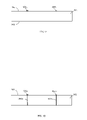
- FIG. 1 shows a cross-sectional view of an example BGA package 100 .
- BGA package 100 includes an IC die/chip 102 , a substrate 104 , bond wires (also known as “wire bonds”) 106 , a plurality of solder balls 108 , and an encapsulating material 110 .
- Substrate 104 has a first (e.g., top) surface 112 that is opposed to a second (e.g., bottom) surface 114 of substrate 104 . As shown in FIG.
- die 102 is mounted to first surface 112 of substrate 104 .
- Die 102 may be mounted to substrate 104 using an adhesive material 118 .
- a plurality of bond wires 106 are coupled between terminals 116 of die 102 and electrically conductive features, such as traces, bond fingers, etc. (not shown in FIG. 1 ), at first surface 112 of substrate 104 .
- Encapsulating material 110 covers die 102 and bond wires 106 on first surface 112 of substrate 104 .
- a plurality of solder balls 108 (including solder balls 108 a and 108 b indicated in FIG. 1 ) is attached to second surface 114 of substrate 104 .
- Solder balls 108 are electrically coupled through substrate 104 (e.g., by electrically conductive vias and/or routing) to the electrically conductive features (e.g., traces, bond fingers, contact regions, etc.) of first surface 112 of substrate 104 to enable signals of die 102 to be electrically connected to solder balls 108 .
- electrically conductive features e.g., traces, bond fingers, contact regions, etc.
- Package 100 may be stacked with a second integrated circuit package to form a package-on-package structure.
- FIG. 2 shows a cross-sectional side view of a package-on-package (POP) structure 200 that includes a first package 100 a stacked on a second package 100 b .
- POP package-on-package
- First and second packages 100 a and 100 b are generally similar to package 100 in FIG. 1 .
- solder balls 108 attached to second surface 114 of first package 100 a are coupled to electrically conductive features on first surface 112 of second package 100 b.
- package-on-package structure 200 By forming package-on-package structure 200 , an IC package structure is formed that includes two IC dies, thereby potentially including enhanced processing capability and/or functionality relative to package 100 shown in FIG. 1 . Thus, package-on-package structures are desirable. However, conventional package-on-package structures, such as structure 200 shown in FIG. 2 , are bulkier than single package structures, and thus may be more difficult to integrate into products, particularly products in which space allocated for circuits is limited.
- Wafer-level packaging is an integrated circuit packaging technology where the packaging-related interconnects are applied while the integrated circuit dies or chips are still in wafer form. Thus, much of the packaging occurs at the wafer-level, which is very cost-effective, because many die of the wafer may be processed at the same time. After the packaging-related interconnects are applied, the wafer may be tested and singulated into individual devices, which may be sent directly to customers for their use. Thus, individual packaging of discreet devices is not required. The size of the final package is essentially the size of the corresponding chip, resulting in a very small package solution. Wafer-level packaging is becoming increasingly popular as the demand for increased functionality in small form-factor devices increases. Examples of applications for wafer-level packages include mobile devices such as cell phones, PDAs, and MP3 players, for example.
- the small size of wafer-level packages and the increasing integration of functionality into IC dies are making it increasingly difficult to attach enough pins (e.g., solder balls) to the wafer-level packages so that all desired signals of the dies can be externally interfaced.
- the pins of a device/package are limited to the surface area of the die.
- the pins on the die must be sufficiently spaced to allow end-users to surface mount the packages directly to circuit boards. If enough pins cannot be provided on the die, the end products will be unable to take advantage of the low cost and small size of the wafer-level packages. Such products will then need to use conventional IC packaging, which leads to much larger package sizes and is more costly.
- Embodiments of the present invention enable wafer-level packages to be stacked.
- the wafer-level packages are configured to have more pins than can conventionally be fit on a die surface at a pin pitch that is reasonable for the end-use application.
- Embodiments use routing interconnects to enable pins to be located over a space adjacent to a die, effectively increasing an area of each die.
- the dies may be stacked, providing a further increase in processing capacity and/or functionality in the resulting package-on-package structure relative to conventional packages.
- electrical connections may be formed through the space adjacent to the die of a wafer-level package to enable a second package to be electrically coupled to the wafer-level package.
- Such embodiments are cost-effective, manufacturable, and enable small size packages to be fabricated having large numbers of pins.
- wafer-level ball grid array packages are mainly illustrated in the description below, the examples described herein may be adapted to a variety of types of wafer-level integrated circuit packages and may include applications with more than one integrated circuit die.
- a wafer-level package may be formed as described herein that includes two or more dies (e.g., two adjacent integrated circuit regions of a wafer are singulated from the wafer attached together).
- a second package may be mounted to this multi-die wafer-level package.
- FIG. 3 shows a flowchart 300 , which is a portion of a process for forming integrated circuit packages, according to an embodiment of the present invention.
- the steps of flowchart 300 do not necessarily need to be performed in the order shown. All steps of flowchart 300 do not need to be performed in all embodiments.
- Flowchart 300 is described below with reference to FIGS. 4-10 , for illustrative purposes. Other structural and operational embodiments will be apparent to persons skilled in the relevant art(s) based on the discussion provided herein.
- Flowchart 300 begins with step 302 .
- a wafer is received having a plurality of integrated circuit regions, each integrated circuit region having a plurality of terminals on a surface of the wafer.
- FIG. 4 shows a plan view of a wafer 400 .
- Wafer 400 may be silicon, gallium arsenide, or other wafer type.
- wafer 400 has a surface defined by a plurality of integrated circuit regions 402 (shown as small rectangles in FIG. 4 ).
- Each integrated circuit region 402 is configured to be packaged separately into a separate wafer-level integrated circuit package, such as a wafer-level ball grid array package. Any number of integrated circuit regions 402 may be included in wafer 400 , including 10s, 100s, 1000s, and even larger numbers.
- FIG. 5 shows a cross-sectional view of wafer 400 , showing example first and second integrated circuit regions 402 a and 202 b .
- integrated circuit regions 402 a and 402 b each include a plurality of terminals 502 (e.g., terminals 502 a - 502 c ).
- Terminals 502 are access points for electrical signals (e.g., input-output signals, power signals, ground signals, test signals, etc.) of integrated circuit regions 402 .
- Any number of terminals 502 may be present on the surface of wafer 400 for each integrated circuit region 402 , including 10s, 100s, and even larger numbers of terminals 502 .
- step 304 the received wafer is thinned by backgrinding.
- Step 304 is optional.
- a backgrinding process may be performed on wafer 400 to reduce a thickness of wafer 400 to a desired amount, if desired and/or necessary.
- thinning of wafer 400 does not necessarily need to be performed in all embodiments.
- Wafer 400 may be thinned in any manner, as would be known to persons skilled in the relevant art(s) (e.g., a backgrinding process).
- FIG. 6 shows a cross-sectional view of wafer 400 after having been thinned according to step 304 , resulting in a thinned wafer 600 .
- wafer 400 is made as thin as possible to aid in minimizing a thickness of resulting packages that will include integrated circuit regions 402 .
- flowchart 300 may optionally include the step of applying an adhesive material to a non-active surface of the wafer.
- FIG. 7 shows a cross-sectional view of thinned wafer 600 , with an adhesive material 702 applied to a non-active surface 704 of thinned wafer 600 .
- Any suitable type of adhesive material may be used for adhesive material 702 , including an epoxy, a conventional die-attach material, adhesive film, etc. This step is not necessarily performed in all embodiments, as further described below.
- step 306 the wafer is singulated into a plurality of integrated circuit dies that each includes an integrated circuit region of the plurality of integrated circuit regions.
- Wafer 400 may be singulated/diced in any appropriate manner to physically separate the integrated circuit regions from each other, as would be known to persons skilled in the relevant art(s).
- wafer 400 may be singulated by a saw, router, laser, etc., in a conventional or other fashion.
- FIG. 8 shows a cross-sectional view of integrated circuit regions 402 a and 402 b having been singulated from each other (also including adhesive material 702 a and 702 b , respectively) into dies 802 a and 802 b , respectively.
- Singulation of wafer 400 may result in 10s, 100s, 1000s, or even larger numbers of dies 802 , depending on a number of integrated circuit regions 402 of wafer 400 .
- FIG. 9 shows a cross-sectional view of a substrate 902 , according to an example embodiment.
- Substrate 902 may be referred to as a “dummy” substrate.
- substrate 902 has opposing first and second surfaces 904 and 906 .
- first and second electrically conductive features 908 a and 908 b are formed on first surface 904 . Any number of electrically conductive features 908 may be formed on substrate 902 .
- Electrically conductive features 908 may be formed of any suitable electrically conductive material, including a metal such as a solder or solder alloy, copper, aluminum, gold, silver, nickel, tin, titanium, a combination of metals/alloy, etc. Electrically conductive features 908 may be formed in any manner, including sputtering, plating, lithographic processes, etc., as would be known to persons skilled in the relevant art(s). Electrically conductive features 908 may be formed in any shape, including as traces/routing, as via capture pads (e.g., circular), etc.
- a plurality of electrically conductive paths is formed through the substrate that are electrically coupled to the first plurality of electrically conductive features on the first surface of the substrate.
- FIG. 10 shows a cross-sectional view of substrate 902 of FIG. 9 , with first and second electrically conductive paths 1002 a and 1002 b formed through substrate 902 .
- electrically conductive path 1002 a is coupled to electrically conductive feature 908 a at first surface 904 of substrate 902
- electrically conductive path 1002 b is coupled to electrically conductive feature 908 b at first surface 904 of substrate 902 .
- Any number of electrically conductive paths 1002 may be formed through substrate 902 , corresponding to electrically conductive features 908 .
- Electrically conductive paths 1002 may be formed in any manner, including being formed as electrically conductive vias through substrate 902 .
- openings may be formed through substrate 902 from first surface 904 to second surface 904 (e.g., by drilling, etching, etc.) that are subsequently filled and/or plated with an electrically conductive material, such as a metal including a solder or solder alloy, copper, aluminum, gold, silver, nickel, tin, titanium, a combination of metals/alloy, etc.
- the openings may be formed in any manner, including by drilling (e.g., mechanical drilling, laser drilling, etc.), by an etching process (e.g., reactive ion etching (RIE)), by a developing process (e.g., where substrate 902 is a polymer), etc.
- Electrically conductive paths 1002 may be filled and/or plated with the electrically conductive material at the same time that electrically conductive features 908 are formed (step 308 ), or may be filled and/or plated separately.
- FIGS. 11-19 are described as follows with respect to a first embodiment for forming integrated circuit packages, while FIGS. 20 - 28 are described in a subsequent subsection with respect to another embodiment for forming integrated circuit packages.
- FIG. 11 shows a flowchart 1100 providing additional steps for flowchart 300 to form integrated circuit packages, according to an embodiment of the present invention.
- the steps of flowchart 1100 do not necessarily need to be performed in the order shown. All steps of flowchart 1100 do not need to be performed in all embodiments.
- Flowchart 1100 is described below with reference to FIGS. 12-19 , for illustrative purposes. Other structural and operational embodiments will be apparent to persons skilled in the relevant art(s) based on the discussion provided herein.
- a non-active surface of each of the plurality of dies is attached to the first surface of the substrate such that the dies are spaced apart on the substrate in a predetermined arrangement.
- FIG. 12 shows a cross-sectional view of dies 802 a and 802 b attached to first surface 904 of substrate 902 .
- the non-active surface (i.e., surface 704 shown in FIG. 7 ) of each of dies 802 a and 802 b is attached to first surface 704 of substrate 902 by adhesive material 702 a and 702 b .
- dies 802 a and 802 b may be positioned on substrate 902 in any manner, including through the use of a pick-and-place apparatus. After positioning of dies 802 a and 802 b , adhesive material 702 a and 702 b may be cured to cause dies 802 a and 802 b to become attached to substrate 902 . Note that in embodiments, adhesive material 702 may be applied to first surface 904 of substrate 902 alternatively to, or in addition to applying adhesive material 702 on wafer 400 /dies 802 , as described above.
- Substrate 902 can be any type of substrate material, including a dielectric material, a ceramic, a polymer, a semiconductor material, etc.
- substrate 902 may be a wafer of a same material as wafer 400 .
- wafer 400 and substrate 902 may both be silicon wafers.
- same material dies 802 and substrate 902 will react similarly, such as by expanding or contracting uniformly, and thus will be less likely to detach from each other and less likely deviate from their placed positions to cause registration issues with subsequent lithography steps.
- a substantially planar layer of an insulating material is formed on the first surface of the substrate to cover the dies on the substrate and to fill a space adjacent to each die on the substrate.
- FIG. 13A shows a cross-sectional view of a layer 1304 of an insulating material 1302 applied to substrate 902 to cover dies 802 a and 802 b .
- Insulating material 1302 may be applied in any manner, conventional or otherwise, as would be known to persons skilled in the relevant art(s).
- insulating material 1302 may be applied according to a spin on or dry film process, and subsequently cured/dried, similar to a corresponding wafer-level process.
- Insulating material 1302 is applied such that layer 1304 has a thickness greater than a thickness of dies 802 (and adhesive material 702 ).
- Layer 1304 may be formed or processed (e.g., polished) such that a first surface 1306 of layer 1304 is substantially planar.
- Insulating material 1302 may be an electrically insulating material, such as a polymer, a dielectric material such as a photo-imagable dielectric, and/or other electrically non-conductive material.
- insulating material 1302 covers dies 802 a and 802 b. Furthermore, as shown in FIG. 13A , insulating material 1302 fills spaces 1308 a and 1308 b adjacent to die 802 a on substrate 902 , and fills spaces 1310 a and 1310 b adjacent to die 802 b on substrate 902 . Insulating material 1302 may fill spaces on any number of sides (edges of dies 802 perpendicular to their active surfaces) of dies 802 , including all four sides, in embodiments.
- a second plurality of electrically conductive paths is formed through the insulating material.
- FIG. 13B shows a cross-sectional view of insulating material 1302 on substrate 902 , as in FIG. 13A , with first and second electrically conductive paths 1320 a and 1320 b formed through insulating material 1302 .
- a first end of electrically conductive path 1320 a is coupled to electrically conductive feature 908 a
- a first end of electrically conductive path 1320 b is coupled to electrically conductive feature 908 b .
- electrically conductive paths 1002 a and 1320 a may be formed to be coaxially aligned.
- electrically conductive paths 1002 a and 1320 a may not be coaxially aligned, but electrically conductive feature 908 a may be elongated (e.g., may include a trace or other routing) on substrate 902 to electrically connect the first ends of electrically conductive paths 1002 a and 1320 a.
- Second ends of electrically conductive paths 1320 a and 1320 b are exposed at a surface of insulating material 1302 .
- First electrically conductive path 1320 a is formed through insulating material 1302 in space 1308 a adjacent to die 802 a
- second electrically conductive path 1320 b is formed through insulating material 1302 in space 1310 a adjacent to die 802 b .
- Electrically conductive paths 1320 may be formed through insulating material 1302 in any manner, including in the manner described above for electrically conductive paths 1002 .
- openings may be formed through insulating material 1302 in any manner, including by drilling (e.g., mechanical drilling, laser drilling, etc.), by an etching process, by a developing process (e.g., where insulating material 1302 is a polymer), etc.
- the openings may subsequently be plated and/or filled with an electrically conductive material to form electrically conductive paths 1320 .
- At least one redistribution interconnect is formed on the insulating material for each die to have a first portion coupled to a terminal of the die and a second portion that extends away from the first portion over a portion of the space adjacent to the die, the second portion being coupled to an electrically conductive path of the second plurality of electrically conductive paths.
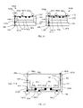
- FIG. 16 shows redistribution interconnects 1602 a - 1602 c , also known as “redistribution layers (RDLs),” formed on insulating material 1302 for each of dies 802 a and 802 b .
- redistribution interconnect 1602 a has a first portion 1604 and a second portion 1606 .
- First portion 1604 is coupled to a terminal of die 802 a.
- Second portion 1606 extends away from first portion 1604 (e.g., laterally) over insulating material 1302 , over a portion of space 1308 a adjacent to die 802 a .
- second portion 1606 of redistribution interconnect 1602 a at die 802 a is connected to electrically conductive path 1320 a
- second portion 1606 of redistribution interconnect 1602 a at die 802 b is connected to electrically conductive path 1320 b .
- redistribution interconnects 1602 may extend over a space adjacent to a die 802 .
- redistribution interconnects 1602 b and 1602 c coupled to terminals of die 802 a do not extend over a space adjacent to die 802 a.
- Redistribution interconnects 1602 may be formed in step 1106 in any manner, including being formed according to processes used in standard wafer-level packaging fabrication processes.
- FIG. 14 shows a flowchart 1400 providing example steps for forming redistribution interconnects 1602 , according to an embodiment of the present invention. Not all steps of flowchart 1400 need to be performed in all embodiments, and that redistribution interconnects 1602 may be formed according to processes other than flowchart 1400 .
- Flowchart 1400 is described below with respect to FIGS. 15-19 , for illustrative purposes.
- Flowchart 1400 begins with step 1402 .
- a plurality of first vias is formed through the substantially planar layer of the insulating material to provide access to the plurality of terminals.
- FIG. 15 shows a cross-sectional view of substrate 902 , with dies 802 a and 802 b covered on substrate 902 with insulating material 1302 .
- a plurality of vias 1502 a - 1502 c are formed through insulating material 1302 for both of dies 802 a and 802 b .
- Each via 1502 provides access to a respective terminal (e.g., one of terminals 302 shown in FIG. 3 ).
- vias 1502 may be present, depending on a number of terminals present.
- vias 1502 may have straight vertical walls (e.g., vias 1502 may have a cylindrical shape) as shown in FIG. 10 , may have sloped/tapered walls, or may have other shapes.
- Vias 1502 may be formed in any manner, including by etching, drilling, developing, etc., as would be known to persons skilled in the relevant art(s).
- a plurality of redistribution interconnects is formed on the substantially planar layer of the insulating material, the first portion of each redistribution interconnect being in contact with a respective terminal though a respective first via.
- routing interconnects 1602 a - 1602 c are formed on insulating material 1302 for each of dies 802 a and 802 b .
- routing interconnect 1602 a has a first portion 1604 and a second portion 1606 .
- First portion 1604 of routing interconnect 1602 a is in contact with a terminal of die 802 a through via 1502 a (formed in step 1402 ), and second portion 1606 of routing interconnect 1602 a extends (e.g., laterally) over insulating material 1302 to be coupled with electrically conductive path 1320 a .
- a plurality of redistribution layers 1602 are formed for dies 802 a and 802 b , at least some of which extend over the space adjacent to dies 802 .
- second portions 1606 of routing interconnects 1602 can have various shapes.
- second portions 1606 may be rectangular shaped, may have a rounded shape, or may have other shapes.
- first portion 1604 of routing interconnects 1602 may be similar to a standard via pad plating, and second portion 1606 may extend from first portion 1604 in a similar fashion as a standard metal trace or routing formed on a substrate.
- Routing interconnects 1602 may be formed of any suitable electrically conductive material, including a metal such as a solder or solder alloy, copper, aluminum, gold, silver, nickel, tin, titanium, a combination of metals/alloy, etc. Routing interconnects 1602 may be formed in any manner, including sputtering, plating, lithographic processes, etc., as would be known to persons skilled in the relevant art(s).
- a second layer of insulating material is formed over the substantially planar layer of insulating material and the plurality of redistribution interconnects.
- FIG. 17 shows a cross-sectional view of a second layer 1704 of an insulating material 1702 formed over first layer 1304 of insulating material 1302 and redistribution interconnects 1602 .
- Second insulating material 1702 may be applied in any manner, conventional or otherwise, as would be known to persons skilled in the relevant art(s).
- insulating material 1702 may be applied according to a spin on or dry film process, similar to a corresponding wafer-level process.
- Insulating material 1702 is applied such that layer 1704 electrically insulates a top surface of redistribution interconnects 1602 .
- Layer 1704 may be formed or processed (e.g., polished) to be substantially planar.
- Insulating material 1702 may be the same material or a different material from insulating material 1302 .
- insulating material 1702 may be an electrically insulating material, such as a polymer, a dielectric material such as a photo-imagable dielectric, and/or other electrically non-conductive material.
- a plurality of second vias is formed through the second layer of insulating material to provide access to the second portion of each of the plurality of redistribution interconnects.
- FIG. 18 shows a cross-sectional view of second vias 1802 a - 1802 c formed through second insulating material 1702 for each of dies 802 a and 802 b to provide access to second portions 1606 of redistribution interconnects 1602 a - 1602 c , respectively.
- Each second via 1802 provides access to a respective redistribution interconnect 1602 . Any number of second vias 1802 may be present, depending on a number of redistribution interconnects present.
- second vias 1802 may have sloped walls as shown in FIG. 18 , may have straight vertical walls (e.g., vias 1802 may have a cylindrical shape), or may have other shapes. Second vias 1802 may be formed in any manner, including by etching, drilling, etc., as would be known to persons skilled in the relevant art(s).
- a plurality of under bump metallization layers is formed on the second layer of insulating material such that each under bump metallization layer is in contact with the second portion of a respective redistribution interconnect though a respective second via.
- FIG. 19 shows a cross-sectional view of under bump metallization layers 1902 a - 1902 c formed in contact with second portions 1606 of respective redistribution interconnects 1602 through respective second vias 1802 .
- Under bump metallization (UBM) layers 1902 are typically one or more metal layers formed (e.g., by metal deposition—plating, sputtering, etc.) to provide a robust interface between redistribution interconnects 1602 and a package interconnect mechanism (such as a ball interconnect).
- a UBM layer serves as a solderable layer for a solder package interconnect mechanism.
- a UBM provides protection for underlying metal or circuitry from chemical/thermal/electrical interactions between the various metals/alloys used for the package interconnect mechanism.
- UBM layers 1902 are formed similarly to standard via plating.
- steps of flowchart 1400 may be repeated any number of times, to create further layers of redistribution interconnects.
- FIG. 17 shows layer 1704 formed over a first layer of redistribution interconnects 1602 .
- Steps 1404 and 1406 may be repeated, to form a second layer of redistribution interconnects 1602 on first layer 1704 in FIG. 17 , and to form a next layer of insulating material 1702 , similar to layer 1704 , on the second layer of redistribution interconnects 1602 .
- Steps 1404 and 1406 may be repeated any number of times, to form a stack of alternating layers of redistribution interconnects 1602 and insulating material 1702 of any suitable height.
- step 1408 may be performed to form second vias 1802 through the multiple layers of insulating material 1702 to provide access to second portions 1606 of the redistribution interconnects 1602 of each formed layer of redistribution interconnects 1602 .
- step 1410 may be performed to form under bump metallization layers 1902 in second vias 1802 that are in contact with redistribution interconnects 1602 at each formed layer of redistribution interconnects 1602 .
- FIG. 20 shows a flowchart 2000 providing additional steps for flowchart 300 to form integrated circuit packages, according to an embodiment of the present invention.
- flowchart 2000 may be performed alternatively to flowchart 1100 shown in FIG. 11 .
- the steps of flowchart 2000 do not necessarily need to be performed in the order shown. All steps of flowchart 2000 do not need to be performed in all embodiments.
- Flowchart 2000 is described below with reference to FIGS. 21-28 , for illustrative purposes. Other structural and operational embodiments will be apparent to persons skilled in the relevant art(s) based on the discussion provided herein.
- FIG. 21 shows a top view of substrate 902 described above ( FIG. 10 ) that may be processed in step 2002 , according to an example embodiment of the present invention.
- substrate 902 can be any type of substrate material.
- Substrate 902 may be considered a “dummy” substrate, because substrate 902 may optionally be partially or entirely removed from dies 802 in a subsequent processing step, as described further below.
- FIG. 22 shows a layer of a thick film material 2202 formed on a first surface 904 of substrate 902 .
- Thick film material 2202 may be applied in any manner, conventional or otherwise, as would be known to persons skilled in the relevant art(s).
- thick film material 2202 may be applied according to a spin on or dry film process, and subsequently cured/dried, similar to a corresponding wafer-level process.
- Thick film material 2202 may have a thickness less than, equal to, or greater than a thickness of dies 802 (and adhesive material 702 ).
- thick film material 2202 may have a thickness in the range of 50-200 ⁇ m.
- the thickness of thick film material 2202 can be controlled by modifying parameters of the process used to form thick film material 2202 , and/or by forming multiple layers of thick film material 2202 on first surface 904 (e.g., to stack layers of thick film material 2202 ).
- Thick film material 2202 may be formed or processed (e.g., polished) such that a substantially planar surface for thick film material 2202 is formed on substrate 902 .
- Thick film material 2202 may be an electrically insulating material, such as a polymer, a dielectric material such as a photo-imagable dielectric, a standard spin-on dielectric material, and/or other suitable thick film material.
- thick film material 2202 may be SU-8 2000 or SU-8 3000 , which are epoxy based photoresist materials supplied by MicroChem Corp. of Newton, Mass.
- FIG. 23 shows a cross-sectional view of substrate 902 and thick film material 2202 , with a plurality of openings 2302 formed in thick film material 2202 , according to an example embodiment of the present invention.
- FIG. 24 shows a top view of a portion of substrate 902 , with openings 2302 formed in thick film material 2202 (in an embodiment where substrate 902 is a circular wafer). Openings 2302 may be formed/patterned in thick film material 2202 in any arrangement, including in an array of rows and columns of openings 2302 , as shown in FIG. 24 . Openings 2302 may have a depth of an entire thickness of thick film material 2202 (as shown in FIG.
- Openings 2302 may have any shape, including being round, rectangular (as shown in FIG. 23 ), other polygon, or irregular. Openings 2302 may be formed in thick film material 2202 in any suitable manner, including by etching (e.g., by laser etching, by a photolithographic process, by chemical etching, by mechanical etching, etc.), by developing, by drilling, or by other suitable process.
- etching e.g., by laser etching, by a photolithographic process, by chemical etching, by mechanical etching, etc.
- a non-active surface of each of the plurality of dies is attached to the first surface of the substrate in a corresponding opening of the plurality of openings.
- FIG. 25 shows a cross-sectional view of dies 802 a and 802 b attached to first surface 904 of substrate 902 in respective openings 2302 a and 2302 b .
- FIG. 26 shows a top view of the portion of substrate 902 shown in FIG. 25 , with dies 802 positioned in openings 2302 .
- the non-active surface i.e., surface 704 shown in FIG.
- each of dies 802 a and 802 b is attached to first surface 904 of substrate 902 by adhesive material 702 a and 702 b .
- dies 802 a and 802 b may be positioned on substrate 902 in openings 2302 a and 2302 b , respectively, in any manner, including through the use of a pick-and-place apparatus, a self-aligning process, or other technique.
- adhesive material 702 a and 702 b may be cured to cause dies 802 a and 802 b to become attached to substrate 902 .
- adhesive material 702 may be applied to first surface 704 of substrate 902 alternatively to, or in addition to applying adhesive material 702 on wafer 400 /dies 802 , as described above.
- a substantially planar layer of an insulating material is formed over the first surface of the substrate to cover the dies in the openings on the substrate.
- FIG. 27A shows a cross-sectional view of a layer 2704 of an insulating material 2702 applied to substrate 902 to cover dies 802 a and 802 b and thick film material 2202 .
- Insulating material 2702 may be applied in any manner, conventional or otherwise, as would be known to persons skilled in the relevant art(s).
- insulating material 2702 may be applied according to a spin on or dry film process, and subsequently cured/dried, similar to a corresponding wafer-level process.
- Insulating material 2702 is applied such that layer 2704 has a thickness greater than a thickness of dies 802 (and adhesive material 702 ).
- Layer 2704 may be formed or processed (e.g., polished) such that a first surface 2706 of layer 2704 is substantially planar.
- Insulating material 2702 may be an electrically insulating material, such as a polymer, a dielectric material such as a photo-imagable dielectric, and/or other electrically non-conductive material.
- insulating material 2702 covers dies 802 a and 802 b. Furthermore, as shown in FIG. 27A , insulating material 2702 fills spaces 2708 a and 2708 b in opening 2302 a adjacent to die 802 a on substrate 902 , and fills spaces 2710 a and 2710 b in opening 2302 b adjacent to die 802 b on substrate 902 . Insulating material 2702 may fill spaces on any number of sides (edges of dies 802 perpendicular to their active surfaces) of dies 802 , including all four sides, in embodiments. Spaces 2708 and 2710 may have any width.
- an opening 2302 may have a size approximately the same as a die 802 residing therein, and thus spaces 2708 and 2710 may be very narrow or non-existent on one or more sides of die 802 . Note that in an embodiment, because dies 802 are located in respective openings 2302 of thick film material 2202 , dies 802 are held relatively stationary during application of insulating material 2702 (as compared to applying insulating material 2702 over dies 802 when thick film material 2202 is not present).
- a second plurality of electrically conductive paths is formed through the insulating material.
- FIG. 27B shows a cross-sectional view of insulating material 2702 on substrate 902 , as in FIG. 27A , with first and second electrically conductive paths 1320 a and 1320 b formed through insulating material 2702 and thick film material 2202 .
- a first end of electrically conductive path 1320 a is coupled to electrically conductive feature 908 a
- a first end of electrically conductive path 1320 b is coupled to electrically conductive feature 908 b .
- Second ends of electrically conductive paths 1320 a and 1320 b are exposed at a surface of insulating material 2702 .
- First electrically conductive path 1320 a is formed adjacent to die 802 a
- second electrically conductive path 1320 b is formed adjacent to die 802 b.
- Electrically conductive paths 1320 may be formed through insulating material 2702 and thick film material 2202 in any manner, including in the manner described above for electrically conductive paths 1002 .
- openings may be formed through insulating material 2702 and thick film material 2202 in any manner, including by drilling (e.g., mechanical drilling, laser drilling, etc.), by an etching process, by a developing process (e.g., where insulating material 2702 and thick film material 2202 are polymers), etc.
- the openings may subsequently be plated and/or filled with an electrically conductive material to form electrically conductive paths 1320 .
- electrically conductive paths 1002 and 1320 may be formed to be coaxially aligned or to not be coaxially aligned.
- step 2012 at least one redistribution interconnect is formed on the insulating material for each die to have a first portion coupled to a terminal of a respective die and a second portion that extends away from the first portion over a portion of the insulating material, the second portion being coupled to an electrically conductive path of the second plurality of electrically conductive paths.
- redistribution interconnects may be formed on insulating material 2702 for each of dies 802 a and 802 b shown in FIG. 27B .
- the redistribution interconnects may be formed in any suitable manner, including according to flowchart 1400 shown in FIG. 14 , and described above. For example, FIG.
- redistribution interconnect 1602 a - 1602 c formed on insulating material 2702 for each of dies 802 a and 802 b .
- redistribution interconnect 1602 a of die 802 a has a first portion 1604 and a second portion 1606 .
- First portion 1604 is coupled to a terminal of die 802 a through via 1502 a .
- Second portion 1606 extends away from first portion 1604 (e.g., laterally) over insulating material 2702 , over a portion of space 1608 a adjacent to die 802 a . As shown in FIG.
- second portion 1606 of redistribution interconnect 1602 a at die 802 a is coupled to electrically conductive path 1320 a
- second portion 1606 of redistribution interconnect 1602 a at die 802 b is coupled to electrically conductive path 1320 b
- An under bump metallization (UBM) layers 1902 a is formed in contact with second portion 1606 of redistribution interconnects 1602 a through a via 1802 a .
- second portion 1606 may extend over space 2708 a (shown in FIG.
- FIG. 29 shows a flowchart 2900 providing additional steps for flowchart 300 to form integrated circuit packages, according to an embodiment of the present invention.
- the steps of flowchart 2900 do not necessarily need to be performed in the order shown. All steps of flowchart 2900 do not need to be performed in all embodiments.
- Flowchart 2900 may be performed with regard to the structures illustrated in FIGS. 19 and 28 , for example. Flowchart 2900 is described below with reference to FIGS. 30-43 , for illustrative purposes. Other structural and operational embodiments will be apparent to persons skilled in the relevant art(s) based on the discussion provided herein.
- the substrate is thinned by backgrinding the substrate.
- Step 2902 is optional.
- a backgrinding process may be performed on substrate 902 to reduce a thickness of substrate 902 to a desired amount, if desired and/or necessary.
- Substrate 902 may be thinned in any manner, as would be known to persons skilled in the relevant art(s). For example, substrate 902 is made as thin as possible to aid in minimizing a thickness of resulting packages that are formed according to the embodiments described herein.
- a ball interconnect is coupled to each second portion.
- FIG. 30 shows a cross-sectional view of the structure shown in FIG. 19 , with substrate 902 having been thinned (according to step 2902 ), and with ball interconnects 3002 a - 3002 c formed on respective UBM layers 1902 a - 1902 c for each of dies 802 a and 802 b .
- a plurality of ball interconnects 3002 may be formed in electrical contact with respective routing interconnects 1602 .
- each ball interconnect 3002 is coupled to a respective redistribution interconnect 1602 (shown as dotted lines). Furthermore, some ball interconnects 3002 are coupled to redistribution interconnects 1602 in a manner such that the ball interconnect 3002 is over insulating material 1702 outside of a periphery of the respective die 802 , instead of in an area within the die periphery. In this manner, an effective area of dies 802 is increased for attachment of ball interconnects 3002 .
- FIG. 32 shows a cross-sectional view of the structure shown in FIG. 28 , with substrate 902 having been thinned (according to step 2902 ), and with ball interconnects 3002 a - 3002 c formed on respective UBM layers 1902 a - 1902 c for each of dies 802 a and 802 b in a similar fashion as shown in FIG. 30 , according to an example embodiment of the present invention.
- FIG. 33 shows a view of a surface of insulating material 1702 of FIG. 32 , where ball interconnects 3002 related to dies 802 a and 802 b (indicated by dotted lines) are visible.
- FIG. 33 shows a view of a surface of insulating material 1702 of FIG. 32 , where ball interconnects 3002 related to dies 802 a and 802 b (indicated by dotted lines) are visible.
- ball interconnect 3002 c slightly overlaps insulating material 2702 (not indicated in FIG. 33 ) in cavity 2302 a outside of the periphery of die 802 a .
- Ball interconnect 3002 a overlaps thick film material 2202 (not indicated in FIG. 33 ) outside of a periphery of cavity 2302 a.
- ball interconnects 3002 a - 3002 c are formed as part of a 3 by 3 array of ball interconnects 3002 for each of dies 802 a and 802 b .
- Arrays of ball interconnects 3002 of any size may be present relating to a particular die 802 , depending on a number of redistribution interconnects 1602 that are present, including hundreds of ball interconnects 3002 .
- Ball interconnects 3002 may be formed of any suitable electrically conductive material, including a metal such as a solder or solder alloy, copper, aluminum, gold, silver, nickel, tin, titanium, a combination of metals/alloy, etc.
- Ball interconnects 3002 may have any size and pitch, as desired for a particular application.
- Ball interconnects 3002 may be any type of ball interconnect, including a solder ball, a solder bump, etc.
- Ball interconnects 3002 may be formed in any manner, including sputtering, plating, lithographic processes, etc., as would be known to persons skilled in the relevant art(s).
- Ball interconnects 3002 are used to interface resulting wafer-level packages with an external device, such as a PCB.
- a second plurality of electrically conductive features is formed on a second surface of the substrate.
- FIG. 34 shows a cross-sectional view of the structure of FIG. 30 , with first and second electrically conductive features 3402 a and 3402 b formed on second surface 906 of substrate 902 .
- a first end of electrically conductive path 1002 a is coupled to electrically conductive feature 3402 a
- a first end of electrically conductive path 1002 b is coupled to electrically conductive feature 3402 b .
- electrically conductive path 1320 a , electrically conductive feature 908 a , electrically conductive path 1002 a , and electrically conductive feature 3402 a form a first electrical connection through insulating material 1302 and substrate 902 , electrically coupling a ball interconnect 3002 a to a terminal of die 802 a and to electrically conductive feature 3402 a .
- Electrically conductive path 1320 b , electrically conductive feature 908 b , electrically conductive path 1002 b , and electrically conductive feature 3402 b form a second electrical connection through insulating material 1302 and substrate 902 , electrically coupling a ball interconnect 3002 a to a terminal of die 802 b and to electrically conductive feature 3402 b .
- Electrically conductive features 3402 may be formed on substrate 902 in any manner, including in the manner described above for electrically conductive features 908 (e.g., in any shape, including traces/routing, via capture pads (e.g., circular) aligned with an axis of a conductive path 1002 , etc.).
- FIG. 35 shows a cross-sectional view of the structure of FIG. 32 , with first and second electrically conductive features 3402 a and 3402 b formed on second surface 906 of substrate 902 .
- Electrically conductive path 1320 a , electrically conductive feature 908 a , electrically conductive path 1002 a , and electrically conductive feature 3402 a form a first electrical connection through insulating material 2702 , thick film material 2202 , and substrate 902 , electrically coupling a ball interconnect 3002 a to a terminal of die 802 a and to electrically conductive feature 3402 a .
- Electrically conductive path 1320 b , electrically conductive feature 908 b , electrically conductive path 1002 b , and electrically conductive feature 3402 b form a second electrical connection through insulating material 2702 , thick film material 2202 , and substrate 902 , electrically coupling a ball interconnect 3002 a to a terminal of die 802 b and to electrically conductive feature 3402 b.
- the dies are singulated into a plurality of integrated circuit packages that each include a die and the portion of the space adjacent to the included die.
- Dies 802 may be singulated/diced in any appropriate manner to physically separate the dies from each other, as would be known to persons skilled in the relevant art(s). Singulation according to step 2908 may result in 10s, 100s, 1000s, or even larger numbers of integrated circuit packages, depending on a number of dies 802 that are present. Dies 802 may be singulated by a saw, router, laser, etc., in a conventional or other fashion. Referring to FIG.
- dies 802 may be singulated by cutting through first and second insulating material layers 1302 and 1702 , and substrate 902 , to separate dies 802 from each other, with each die 802 including a portion of its adjacent space.
- dies 802 may be singulated by cutting through first and second insulating material layers 2702 and 1702 , thick film material 2202 , and substrate 902 , to separate dies 802 from each other, with each die 802 including a portion of its adjacent space.
- FIG. 36 shows a cross-sectional view of the structure of FIG. 34 having been singulated into first and second packages 3602 a and 3602 b .
- Integrated circuit packages 3602 a and 3602 b respectively include dies 802 a and 802 b , and respective portions 3604 a and 3604 b of adjacent space that are filled with insulating material 1302 .
- Second portions 1606 of redistribution interconnects 1602 a extend over portions 3604 a and 3604 b of the adjacent space included with singulated dies 802 a and 802 b , respectively.
- FIG. 37 shows a cross-sectional view of an integrated circuit package 3602 , which has been inverted relative to FIG. 36 .
- package 3602 includes a first interconnection structure that includes electrically conductive path 1320 a , electrically conductive feature 908 a , electrically conductive path 1002 a , and electrically conductive feature 3402 a , and a second interconnection structure that includes electrically conductive path 1320 b , electrically conductive feature 908 b , electrically conductive path 1002 b , and electrically conductive feature 3402 b .
- Any number of such interconnection structures may be present in a package to form an electrical connection through the package that is also coupled to a terminal of the included die.
- Package 3602 may be formed in the manner that packages 3602 a and 3602 b of FIG. 36 are formed (e.g., according to flowcharts 300 , 1100 , and 2900 ). Alternatively, package 3602 may be formed by other fabrication process, including by forming package 3602 individually. As shown in FIG. 36 , package 3602 includes die 802 , which has a plurality of terminals 502 a - 502 c on a first surface, insulating material 1302 , redistribution interconnects 1602 a - 1602 c , and ball interconnects 3002 a - 3002 c . Insulating material 1302 covers the active surface of die 802 , and fills space 3404 adjacent one or more sides of die 802 .
- Redistribution interconnect 1602 a on insulating material 1302 has first portion 1604 coupled to terminal 502 a of die 802 through insulating material 1302 , and has second portion 1606 that extends away from first portion 1604 over insulating material 1302 .
- Ball interconnect 3002 a is coupled to second portion 1606 of redistribution interconnect 1602 a over space 3404 .
- redistribution interconnect 1602 effectively expands an area of die 802 for attachment of ball interconnects.
- FIG. 38 show a bottom view of package 3602 , where ball interconnects 3002 a - 3002 c form a portion of a 3 by 3 array of ball interconnects 3002 .
- Ball interconnects 3002 are used to attach package 3402 to a circuit board.
- three ball interconnects 3002 including ball interconnect 3002 a , are coupled through redistribution interconnects 1602 , such as redistribution interconnect 1602 a , to terminals of die 802 .
- the three ball interconnects 3002 are over space 3604 adjacent to die 802 .
- the area of die 802 is effectively increased by an area of space 3604 for attachment of three additional ball interconnects 3002 .
- Embodiments of the present invention enable the attachment of any number of ball interconnects 3002 , depending on the particular implementation, as would be known to persons skilled in the relevant art(s) from the teachings herein.
- FIG. 39 shows a cross-sectional view of the structure of FIG. 35 having been singulated into first and second packages 3902 a and 3902 b .
- Integrated circuit packages 3902 a and 3902 b respectively include dies 802 a and 802 b , and respective portions 3904 a and 3904 b of adjacent space that are filled with insulating material 2702 , and which may further include thick film material 2202 .
- Second portions 1606 of redistribution interconnects 1602 a extend over portions 3904 a and 3904 b of the adjacent space included with singulated dies 802 a and 802 b , respectively.
- FIG. 40 shows a cross-sectional view of an integrated circuit package 3902 , which has been inverted relative to FIG. 39 .
- package 3902 includes a first interconnection structure that includes electrically conductive path 1320 a , electrically conductive feature 908 a , electrically conductive path 1002 a , and electrically conductive feature 3402 a , and a second interconnection structure that includes electrically conductive path 1320 b , electrically conductive feature 908 b , electrically conductive path 1002 b , and electrically conductive feature 3402 b (electrically conductive feature 3402 b is elongated in FIG. 40 to extend away from an edge of package 3902 ).
- Integrated circuit package 3902 is an example wafer-level package, formed according to an embodiment of the present invention.
- Package 3902 may be formed in the manner that packages 3902 a and 3902 b of FIG. 39 are formed (e.g., according to flowcharts 300 , 2000 , and 2900 ).
- package 3902 may be formed by other fabrication process, including by forming package 3902 individually. As shown in FIG.
- package 3902 includes die 802 , which has a plurality of terminals 502 a - 502 c on a first surface, insulating material 2702 , thick film material 2202 , redistribution interconnects 1602 a - 1602 c , and ball interconnects 3002 a - 3002 c .
- Insulating material 2702 covers the active surface of die 802 , and fills space 3904 adjacent one or more sides of die 802 in opening 2302 formed by thick film material 2202 .
- Thick film material 2202 may form a partial or complete ring around die 802 .
- Redistribution interconnect 1602 a on insulating material 2702 has first portion 1604 coupled to terminal 502 a of die 802 through insulating material 2702 , and has second portion 1606 that extends away from first portion 1706 over insulating material 2702 and thick film material 2202 .
- Ball interconnect 3002 a is coupled to second portion 1606 of redistribution interconnect 1602 a over space 3904 .
- redistribution interconnect 1602 effectively expands an area of die 802 for attachment of ball interconnects.
- FIG. 41 show a bottom view of package 3902 , where ball interconnects 3002 a - 3002 c form a portion of a 3 by 3 array of ball interconnects 3002 .
- Ball interconnects 3002 are used to attach package 3902 a circuit board.
- three ball interconnects 3002 including ball interconnect 3002 a , are coupled through redistribution interconnects 1602 , such as redistribution interconnect 1602 a , to terminals of die 802 .
- the three ball interconnects 3002 are over space 3904 adjacent to die 802 .
- the area of die 802 is effectively increased by an area of space 3904 for attachment of three additional ball interconnects 3002 .
- Embodiments of the present invention enable the attachment of any number of ball interconnects 3002 , depending on the particular implementation, as would be known to persons skilled in the relevant art(s) from the teachings herein.
- a second integrated circuit package is mounted to each of the plurality of first integrated circuit modules to form a plurality of package-on-package structures.
- Integrated circuit packages formed according to embodiments described herein, such as package 3602 ( FIG. 36-38 ) and package 3902 ( FIGS. 39-41 ) may have a second integrated circuit package mounted to them, to form a package on package structure.
- FIG. 42 shows an example package-on-package structure 4200 , according to an example embodiment of the present invention.
- Structure 4200 is an integrated circuit package that includes package 3602 as a first package, and includes a second integrated circuit package 4202 that is mounted to package 3602 .
- Package 4202 may be any type of integrated circuit package, including a ball grid array package, a pin grid array package, a land grid array package, etc.
- package 4202 includes first and second mounting members 4202 a and 4202 b (e.g., pins, posts, or solder balls as shown in FIG. 42 ) that are attached to electrically conductive features 3402 a and 3402 b on second surface 906 of substrate 902 of package 3602 .
- Any number of mounting members 4202 may be present in package 4202 that are attached to a corresponding number of electrically conductive features 3402 of package 3602 .
- Package 4202 may be attached to package 3602 in any manner, including using a pick-and-place apparatus, reflow soldering, etc.
- an electrical connection is formed between terminal 502 a of die 802 , ball interconnect 3002 a , and mounting member 4202 by electrically conductive path 1320 a, electrically conductive feature 908 a , electrically conductive path 1002 a , and electrically conductive feature 3402 a , to electrically couple an electrical signal between package 3602 , package 4202 , and a circuit board to which structure 4200 is mounted (using ball interconnects 3002 ). Any number of electrical signals may be coupled between package 3602 and package 4202 in this manner.
- FIG. 43 shows an example package-on-package structure 4300 , according to an example embodiment of the present invention.
- Structure 4300 is an integrated circuit package that includes package 3902 as a first package, and includes second integrated circuit package 4202 , which is mounted to package 3902 .
- package 4202 includes first and second mounting members 4202 a and 4202 b that are attached to electrically conductive features 3402 a and 3402 b on second surface 906 of substrate 902 of package 3902 .
- Any number of mounting members 4202 may be present in package 4202 that are attached to a corresponding number of electrically conductive features 3402 of package 3902 .
- Package 4202 may be attached to package 3902 in any manner, including using a pick-and-place apparatus, reflow soldering, etc.
- an electrical connection is formed between terminal 502 a of die 802 , ball interconnect 3002 a , and mounting member 4202 by electrically conductive path 1320 a, electrically conductive feature 908 a , electrically conductive path 1002 a , and electrically conductive feature 3402 a , to electrically couple an electrical signal between package 3902 , package 4202 , and a circuit board to which structure 4300 is mounted (using ball interconnects 3002 ). Any number of electrical signals may be coupled between package 3902 and package 4202 in this manner.
- embodiments enable a Package-on-Package approach to achieving integration of additional devices into wafer-level technologies to create new/additional functionality without incurring additional area penalty in the end-use application.
- additional functionality include adding a logic/mixed signal chip, adding a memory chip, and/or adding any further type of chip (enclosed in a second package) to a package embodiment described herein.
- Embodiments enable Package-on-Package to be used with the fan-out wafer-level packaging technology.
Abstract
Description
Claims (20)
Priority Applications (1)
| Application Number | Priority Date | Filing Date | Title |
|---|---|---|---|
| US12/512,313 US8643164B2 (en) | 2009-06-11 | 2009-07-30 | Package-on-package technology for fan-out wafer-level packaging |
Applications Claiming Priority (2)
| Application Number | Priority Date | Filing Date | Title |
|---|---|---|---|
| US18604409P | 2009-06-11 | 2009-06-11 | |
| US12/512,313 US8643164B2 (en) | 2009-06-11 | 2009-07-30 | Package-on-package technology for fan-out wafer-level packaging |
Publications (2)
| Publication Number | Publication Date |
|---|---|
| US20100314739A1 US20100314739A1 (en) | 2010-12-16 |
| US8643164B2 true US8643164B2 (en) | 2014-02-04 |
Family
ID=43305715
Family Applications (1)
| Application Number | Title | Priority Date | Filing Date |
|---|---|---|---|
| US12/512,313 Active 2030-07-03 US8643164B2 (en) | 2009-06-11 | 2009-07-30 | Package-on-package technology for fan-out wafer-level packaging |
Country Status (1)
| Country | Link |
|---|---|
| US (1) | US8643164B2 (en) |
Cited By (6)
| Publication number | Priority date | Publication date | Assignee | Title |
|---|---|---|---|---|
| US20150155256A1 (en) * | 2013-12-04 | 2015-06-04 | Bridge Semiconductor Corporation | Semiconductor package with package-on-package stacking capability and method of manufacturing the same |
| WO2017049510A1 (en) * | 2015-09-23 | 2017-03-30 | Intel Corporation | Substrates, assemblies, and techniques to enable multi-chip flip chip packages |
| US9754849B2 (en) * | 2014-12-23 | 2017-09-05 | Intel Corporation | Organic-inorganic hybrid structure for integrated circuit packages |
| KR20200038279A (en) | 2017-09-11 | 2020-04-10 | 라이징 테크놀로지즈 가부시키가이샤 | Electronic circuit device and manufacturing method of electronic circuit device |
| WO2020208984A1 (en) | 2019-04-12 | 2020-10-15 | 株式会社ライジングテクノロジーズ | Electronic circuit device and method for manufacturing electronic circuit device |
| US11557542B2 (en) | 2019-05-16 | 2023-01-17 | Rising Technologies Co., Ltd. | Electronic circuit device and method of manufacturing electronic circuit device |
Families Citing this family (9)
| Publication number | Priority date | Publication date | Assignee | Title |
|---|---|---|---|---|
| US8693518B2 (en) * | 2009-09-09 | 2014-04-08 | Merkle International Inc. | High temperature industrial furnace roof system |
| KR101665556B1 (en) * | 2009-11-19 | 2016-10-13 | 삼성전자 주식회사 | Semiconductor package having multi pitch ball land |
| JP2013030593A (en) * | 2011-07-28 | 2013-02-07 | J Devices:Kk | Semiconductor devices, semiconductor module structure formed by vertically laminated semiconductor devices, and manufacturing method of semiconductor module structure |
| US9105552B2 (en) | 2011-10-31 | 2015-08-11 | Taiwan Semiconductor Manufacturing Company, Ltd. | Package on package devices and methods of packaging semiconductor dies |
| KR101831938B1 (en) | 2011-12-09 | 2018-02-23 | 삼성전자주식회사 | Method of fabricating fan-out wafer level pacakge and the package formed by the method |
| US9171790B2 (en) * | 2012-05-30 | 2015-10-27 | Taiwan Semiconductor Manufacturing Company, Ltd. | Package on package devices and methods of packaging semiconductor dies |
| US10090376B2 (en) * | 2013-10-29 | 2018-10-02 | Micron Technology, Inc. | Methods of forming semiconductor device structures, and methods of forming capacitor structures |
| US9559064B2 (en) | 2013-12-04 | 2017-01-31 | Taiwan Semiconductor Manufacturing Company, Ltd. | Warpage control in package-on-package structures |
| DE102015109764A1 (en) * | 2015-06-18 | 2016-12-22 | Infineon Technologies Ag | A laminar structure, a semiconductor device, and method of forming semiconductor devices |
Citations (28)
| Publication number | Priority date | Publication date | Assignee | Title |
|---|---|---|---|---|
| US5111278A (en) * | 1991-03-27 | 1992-05-05 | Eichelberger Charles W | Three-dimensional multichip module systems |
| US5442234A (en) | 1992-09-10 | 1995-08-15 | Vlsi Technology, Inc. | Apparatus for thermally coupling a heat sink to a leadframe |
| WO1996031905A1 (en) | 1995-04-05 | 1996-10-10 | Mcnc | A solder bump structure for a microelectronic substrate |
| US5818105A (en) | 1994-07-22 | 1998-10-06 | Nec Corporation | Semiconductor device with plastic material covering a semiconductor chip mounted on a substrate of the device |
| US6154366A (en) | 1999-11-23 | 2000-11-28 | Intel Corporation | Structures and processes for fabricating moisture resistant chip-on-flex packages |
| US6271469B1 (en) | 1999-11-12 | 2001-08-07 | Intel Corporation | Direct build-up layer on an encapsulated die package |
| US20020020855A1 (en) | 1999-09-29 | 2002-02-21 | Hwang Chan Seung | Method for fabricating a semiconductor device |
| US6506632B1 (en) * | 2002-02-15 | 2003-01-14 | Unimicron Technology Corp. | Method of forming IC package having downward-facing chip cavity |
| US20030153172A1 (en) | 2002-02-08 | 2003-08-14 | Hitachi, Ltd. | Method of manufacturing a semiconductor integrated circuit device |
| US6617674B2 (en) | 2001-02-20 | 2003-09-09 | Dow Corning Corporation | Semiconductor package and method of preparing same |
| US6709898B1 (en) | 2000-10-04 | 2004-03-23 | Intel Corporation | Die-in-heat spreader microelectronic package |
| US6734534B1 (en) | 2000-08-16 | 2004-05-11 | Intel Corporation | Microelectronic substrate with integrated devices |
| US6750397B2 (en) * | 2002-02-15 | 2004-06-15 | Advanced Semiconductor Engineering, Inc. | Thermally enhanced semiconductor build-up package |
| JP2004214345A (en) | 2002-12-27 | 2004-07-29 | Renesas Technology Corp | Semiconductor device and its manufacturing method |
| US6867122B2 (en) | 2002-01-07 | 2005-03-15 | Advanced Semiconductor Engineering, Inc. | Redistribution process |
| US6946325B2 (en) * | 2003-03-14 | 2005-09-20 | Micron Technology, Inc. | Methods for packaging microelectronic devices |
| US20050205978A1 (en) * | 2003-01-22 | 2005-09-22 | Han-Ping Pu | Semiconductor package and fabrication method thereof |
| US6965160B2 (en) | 2002-08-15 | 2005-11-15 | Micron Technology, Inc. | Semiconductor dice packages employing at least one redistribution layer |
| US7002245B2 (en) * | 2003-06-09 | 2006-02-21 | Siliconware Precicion Industries Co., Ltd. | Semiconductor package having conductive bumps on chip and method for fabricating the same |
| US20060258137A1 (en) | 2005-05-12 | 2006-11-16 | Siliconware Precision Industries Co., Ltd. | Semiconductor device and fabrication method thereof |
| US20060264021A1 (en) | 2005-05-17 | 2006-11-23 | Intel Corporation | Offset solder bump method and apparatus |
| US7170152B2 (en) | 2004-03-11 | 2007-01-30 | Siliconware Precision Industries Co., Ltd. | Wafer level semiconductor package with build-up layer and method for fabricating the same |
| US20070035015A1 (en) * | 2005-08-15 | 2007-02-15 | Shih-Ping Hsu | Stack structure with semiconductor chip embedded in carrier |
| US7268012B2 (en) | 2004-08-31 | 2007-09-11 | Micron Technology, Inc. | Methods for fabrication of thin semiconductor assemblies including redistribution layers and packages and assemblies formed thereby |
| US7294920B2 (en) * | 2004-07-23 | 2007-11-13 | Industrial Technology Research Institute | Wafer-leveled chip packaging structure and method thereof |
| US20080265408A1 (en) | 2007-04-30 | 2008-10-30 | Broadcom Corporation | Highly Reliable Low Cost Structure for Wafer-Level Ball Grid Array Packaging |
| US7453148B2 (en) * | 2006-12-20 | 2008-11-18 | Advanced Chip Engineering Technology Inc. | Structure of dielectric layers in built-up layers of wafer level package |
| US20090039508A1 (en) | 2007-08-09 | 2009-02-12 | Broadcom Corporation | Larger than die size wafer-level redistribution packaging process |
-
2009
- 2009-07-30 US US12/512,313 patent/US8643164B2/en active Active
Patent Citations (32)
| Publication number | Priority date | Publication date | Assignee | Title |
|---|---|---|---|---|
| US5111278A (en) * | 1991-03-27 | 1992-05-05 | Eichelberger Charles W | Three-dimensional multichip module systems |
| US5442234A (en) | 1992-09-10 | 1995-08-15 | Vlsi Technology, Inc. | Apparatus for thermally coupling a heat sink to a leadframe |
| US5818105A (en) | 1994-07-22 | 1998-10-06 | Nec Corporation | Semiconductor device with plastic material covering a semiconductor chip mounted on a substrate of the device |
| WO1996031905A1 (en) | 1995-04-05 | 1996-10-10 | Mcnc | A solder bump structure for a microelectronic substrate |
| KR19980703571A (en) | 1995-04-05 | 1998-11-05 | 베키 알. 프렌치 | Solder Bump Structure for Microelectronic Substrate |
| US20020020855A1 (en) | 1999-09-29 | 2002-02-21 | Hwang Chan Seung | Method for fabricating a semiconductor device |
| US6271469B1 (en) | 1999-11-12 | 2001-08-07 | Intel Corporation | Direct build-up layer on an encapsulated die package |
| US6154366A (en) | 1999-11-23 | 2000-11-28 | Intel Corporation | Structures and processes for fabricating moisture resistant chip-on-flex packages |
| US6734534B1 (en) | 2000-08-16 | 2004-05-11 | Intel Corporation | Microelectronic substrate with integrated devices |
| US6709898B1 (en) | 2000-10-04 | 2004-03-23 | Intel Corporation | Die-in-heat spreader microelectronic package |
| US6617674B2 (en) | 2001-02-20 | 2003-09-09 | Dow Corning Corporation | Semiconductor package and method of preparing same |
| US6867122B2 (en) | 2002-01-07 | 2005-03-15 | Advanced Semiconductor Engineering, Inc. | Redistribution process |
| US20030153172A1 (en) | 2002-02-08 | 2003-08-14 | Hitachi, Ltd. | Method of manufacturing a semiconductor integrated circuit device |
| US6750397B2 (en) * | 2002-02-15 | 2004-06-15 | Advanced Semiconductor Engineering, Inc. | Thermally enhanced semiconductor build-up package |
| US6506632B1 (en) * | 2002-02-15 | 2003-01-14 | Unimicron Technology Corp. | Method of forming IC package having downward-facing chip cavity |
| US6965160B2 (en) | 2002-08-15 | 2005-11-15 | Micron Technology, Inc. | Semiconductor dice packages employing at least one redistribution layer |
| JP2004214345A (en) | 2002-12-27 | 2004-07-29 | Renesas Technology Corp | Semiconductor device and its manufacturing method |
| US20050205978A1 (en) * | 2003-01-22 | 2005-09-22 | Han-Ping Pu | Semiconductor package and fabrication method thereof |
| US6946325B2 (en) * | 2003-03-14 | 2005-09-20 | Micron Technology, Inc. | Methods for packaging microelectronic devices |
| US7002245B2 (en) * | 2003-06-09 | 2006-02-21 | Siliconware Precicion Industries Co., Ltd. | Semiconductor package having conductive bumps on chip and method for fabricating the same |
| US7170152B2 (en) | 2004-03-11 | 2007-01-30 | Siliconware Precision Industries Co., Ltd. | Wafer level semiconductor package with build-up layer and method for fabricating the same |
| US7294920B2 (en) * | 2004-07-23 | 2007-11-13 | Industrial Technology Research Institute | Wafer-leveled chip packaging structure and method thereof |
| US7268012B2 (en) | 2004-08-31 | 2007-09-11 | Micron Technology, Inc. | Methods for fabrication of thin semiconductor assemblies including redistribution layers and packages and assemblies formed thereby |
| US20060258137A1 (en) | 2005-05-12 | 2006-11-16 | Siliconware Precision Industries Co., Ltd. | Semiconductor device and fabrication method thereof |
| US20080182401A1 (en) | 2005-05-12 | 2008-07-31 | Siliconware Precision Industries Co., Ltd. | Fabrication method of a semiconductor device |
| US20060264021A1 (en) | 2005-05-17 | 2006-11-23 | Intel Corporation | Offset solder bump method and apparatus |
| US20070035015A1 (en) * | 2005-08-15 | 2007-02-15 | Shih-Ping Hsu | Stack structure with semiconductor chip embedded in carrier |
| US7453148B2 (en) * | 2006-12-20 | 2008-11-18 | Advanced Chip Engineering Technology Inc. | Structure of dielectric layers in built-up layers of wafer level package |
| US20080265408A1 (en) | 2007-04-30 | 2008-10-30 | Broadcom Corporation | Highly Reliable Low Cost Structure for Wafer-Level Ball Grid Array Packaging |
| US7834449B2 (en) | 2007-04-30 | 2010-11-16 | Broadcom Corporation | Highly reliable low cost structure for wafer-level ball grid array packaging |
| US20090039508A1 (en) | 2007-08-09 | 2009-02-12 | Broadcom Corporation | Larger than die size wafer-level redistribution packaging process |
| US7872347B2 (en) | 2007-08-09 | 2011-01-18 | Broadcom Corporation | Larger than die size wafer-level redistribution packaging process |
Non-Patent Citations (1)
| Title |
|---|
| European Search Report Received for EP Patent Application No. 08006073.4, mailed on Sep. 19, 2012, 8 pages. |
Cited By (11)
| Publication number | Priority date | Publication date | Assignee | Title |
|---|---|---|---|---|
| US20150155256A1 (en) * | 2013-12-04 | 2015-06-04 | Bridge Semiconductor Corporation | Semiconductor package with package-on-package stacking capability and method of manufacturing the same |
| US9209154B2 (en) * | 2013-12-04 | 2015-12-08 | Bridge Semiconductor Corporation | Semiconductor package with package-on-package stacking capability and method of manufacturing the same |
| US9754849B2 (en) * | 2014-12-23 | 2017-09-05 | Intel Corporation | Organic-inorganic hybrid structure for integrated circuit packages |
| WO2017049510A1 (en) * | 2015-09-23 | 2017-03-30 | Intel Corporation | Substrates, assemblies, and techniques to enable multi-chip flip chip packages |
| US10748873B2 (en) | 2015-09-23 | 2020-08-18 | Intel Corporation | Substrates, assembles, and techniques to enable multi-chip flip chip packages |
| KR20200038279A (en) | 2017-09-11 | 2020-04-10 | 라이징 테크놀로지즈 가부시키가이샤 | Electronic circuit device and manufacturing method of electronic circuit device |
| US11189571B2 (en) | 2017-09-11 | 2021-11-30 | Rising Technologies Co., Ltd. | Electronic circuit device and method of manufacturing electronic circuit device |
| WO2020208984A1 (en) | 2019-04-12 | 2020-10-15 | 株式会社ライジングテクノロジーズ | Electronic circuit device and method for manufacturing electronic circuit device |
| US11330712B2 (en) | 2019-04-12 | 2022-05-10 | Rising Technologies Co., Ltd. | Electronic circuit device and method of manufacturing electronic circuit device |
| US11696400B2 (en) | 2019-04-12 | 2023-07-04 | Rising Technologies Co., Ltd. | Embedded module |
| US11557542B2 (en) | 2019-05-16 | 2023-01-17 | Rising Technologies Co., Ltd. | Electronic circuit device and method of manufacturing electronic circuit device |
Also Published As
| Publication number | Publication date |
|---|---|
| US20100314739A1 (en) | 2010-12-16 |
Similar Documents
| Publication | Publication Date | Title |
|---|---|---|
| US8643164B2 (en) | Package-on-package technology for fan-out wafer-level packaging | |
| US11342196B2 (en) | Integrated circuit package pad and methods of forming | |
| CN110660754B (en) | Semiconductor package | |
| US7872347B2 (en) | Larger than die size wafer-level redistribution packaging process | |
| US10522476B2 (en) | Package structure, integrated fan-out package and method of fabricating the same | |
| TWI662631B (en) | Semiconductor device and method of stacking semiconductor die on a fan-out wlcsp | |
| US10418255B2 (en) | Semiconductor device packages and related methods | |
| CN112310049A (en) | Integrated circuit package | |
| US11133236B2 (en) | Polymer-based-semiconductor structure with cavity | |
| US11291116B2 (en) | Integrated circuit structure | |
| KR20140034909A (en) | Semiconductor die assemblies, semiconductor devices including same, and methods of fabrication | |
| US20120187545A1 (en) | Direct through via wafer level fanout package | |
| US11854984B2 (en) | Semiconductor package and manufacturing method thereof | |
| US11081369B2 (en) | Package structure and manufacturing method thereof | |
| CN112447642A (en) | Semiconductor package and method of manufacturing the same | |
| US20230089795A1 (en) | Semiconductor package | |
| CN107301981B (en) | Integrated fan-out package and method of manufacture | |
| CN114765110A (en) | Package structure and method for manufacturing the same | |
| US11062998B2 (en) | Semiconductor package and manufacturing method thereof | |
| US20090230554A1 (en) | Wafer-level redistribution packaging with die-containing openings | |
| EP2880684A1 (en) | Reconstituted wafer-level microelectronic package | |
| US11127688B2 (en) | Semiconductor package and manufacturing method thereof | |
| TWI671876B (en) | Stacked package and a manufacturing method of the same | |
| US11538761B2 (en) | Semiconductor package having molded die and semiconductor die and manufacturing method thereof | |
| US20240021491A1 (en) | Semiconductor device and method of forming the same |
Legal Events
| Date | Code | Title | Description |
|---|---|---|---|
| AS | Assignment |
Owner name: BROADCOM CORPORATION, CALIFORNIA Free format text: ASSIGNMENT OF ASSIGNORS INTEREST;ASSIGNORS:KAUFMANN, MATTHEW VERNON;TAN, TECK YANG;SIGNING DATES FROM 20090728 TO 20090730;REEL/FRAME:023027/0514 |
|
| STCF | Information on status: patent grant |
Free format text: PATENTED CASE |
|
| AS | Assignment |
Owner name: BANK OF AMERICA, N.A., AS COLLATERAL AGENT, NORTH CAROLINA Free format text: PATENT SECURITY AGREEMENT;ASSIGNOR:BROADCOM CORPORATION;REEL/FRAME:037806/0001 Effective date: 20160201 Owner name: BANK OF AMERICA, N.A., AS COLLATERAL AGENT, NORTH Free format text: PATENT SECURITY AGREEMENT;ASSIGNOR:BROADCOM CORPORATION;REEL/FRAME:037806/0001 Effective date: 20160201 |
|
| AS | Assignment |
Owner name: AVAGO TECHNOLOGIES GENERAL IP (SINGAPORE) PTE. LTD., SINGAPORE Free format text: ASSIGNMENT OF ASSIGNORS INTEREST;ASSIGNOR:BROADCOM CORPORATION;REEL/FRAME:041706/0001 Effective date: 20170120 Owner name: AVAGO TECHNOLOGIES GENERAL IP (SINGAPORE) PTE. LTD Free format text: ASSIGNMENT OF ASSIGNORS INTEREST;ASSIGNOR:BROADCOM CORPORATION;REEL/FRAME:041706/0001 Effective date: 20170120 |
|
| AS | Assignment |
Owner name: BROADCOM CORPORATION, CALIFORNIA Free format text: TERMINATION AND RELEASE OF SECURITY INTEREST IN PATENTS;ASSIGNOR:BANK OF AMERICA, N.A., AS COLLATERAL AGENT;REEL/FRAME:041712/0001 Effective date: 20170119 |
|
| FPAY | Fee payment |
Year of fee payment: 4 |
|
| AS | Assignment |
Owner name: AVAGO TECHNOLOGIES INTERNATIONAL SALES PTE. LIMITE Free format text: MERGER;ASSIGNOR:AVAGO TECHNOLOGIES GENERAL IP (SINGAPORE) PTE. LTD.;REEL/FRAME:047230/0910 Effective date: 20180509 |
|
| AS | Assignment |
Owner name: AVAGO TECHNOLOGIES INTERNATIONAL SALES PTE. LIMITE Free format text: CORRECTIVE ASSIGNMENT TO CORRECT THE EFFECTIVE DATE OF THE MERGER PREVIOUSLY RECORDED AT REEL: 047230 FRAME: 0910. ASSIGNOR(S) HEREBY CONFIRMS THE MERGER;ASSIGNOR:AVAGO TECHNOLOGIES GENERAL IP (SINGAPORE) PTE. LTD.;REEL/FRAME:047351/0384 Effective date: 20180905 |
|
| AS | Assignment |
Owner name: AVAGO TECHNOLOGIES INTERNATIONAL SALES PTE. LIMITE Free format text: CORRECTIVE ASSIGNMENT TO CORRECT THE ERROR IN RECORDING THE MERGER IN THE INCORRECT US PATENT NO. 8,876,094 PREVIOUSLY RECORDED ON REEL 047351 FRAME 0384. ASSIGNOR(S) HEREBY CONFIRMS THE MERGER;ASSIGNOR:AVAGO TECHNOLOGIES GENERAL IP (SINGAPORE) PTE. LTD.;REEL/FRAME:049248/0558 Effective date: 20180905 |
|
| MAFP | Maintenance fee payment |
Free format text: PAYMENT OF MAINTENANCE FEE, 8TH YEAR, LARGE ENTITY (ORIGINAL EVENT CODE: M1552); ENTITY STATUS OF PATENT OWNER: LARGE ENTITY Year of fee payment: 8 |