US8639511B2 - Robot, method and program of correcting a robot voice in accordance with head movement - Google Patents
Robot, method and program of correcting a robot voice in accordance with head movement Download PDFInfo
- Publication number
- US8639511B2 US8639511B2 US12/881,812 US88181210A US8639511B2 US 8639511 B2 US8639511 B2 US 8639511B2 US 88181210 A US88181210 A US 88181210A US 8639511 B2 US8639511 B2 US 8639511B2
- Authority
- US
- United States
- Prior art keywords
- voice
- unit
- bearing
- robot
- generating
- Prior art date
- Legal status (The legal status is an assumption and is not a legal conclusion. Google has not performed a legal analysis and makes no representation as to the accuracy of the status listed.)
- Active, expires
Links
Images


Classifications
-
- B—PERFORMING OPERATIONS; TRANSPORTING
- B25—HAND TOOLS; PORTABLE POWER-DRIVEN TOOLS; MANIPULATORS
- B25J—MANIPULATORS; CHAMBERS PROVIDED WITH MANIPULATION DEVICES
- B25J11/00—Manipulators not otherwise provided for
- B25J11/0005—Manipulators having means for high-level communication with users, e.g. speech generator, face recognition means
-
- G—PHYSICS
- G10—MUSICAL INSTRUMENTS; ACOUSTICS
- G10L—SPEECH ANALYSIS OR SYNTHESIS; SPEECH RECOGNITION; SPEECH OR VOICE PROCESSING; SPEECH OR AUDIO CODING OR DECODING
- G10L13/00—Speech synthesis; Text to speech systems
- G10L13/02—Methods for producing synthetic speech; Speech synthesisers
- G10L13/027—Concept to speech synthesisers; Generation of natural phrases from machine-based concepts
-
- G—PHYSICS
- G10—MUSICAL INSTRUMENTS; ACOUSTICS
- G10L—SPEECH ANALYSIS OR SYNTHESIS; SPEECH RECOGNITION; SPEECH OR VOICE PROCESSING; SPEECH OR AUDIO CODING OR DECODING
- G10L13/00—Speech synthesis; Text to speech systems
- G10L13/02—Methods for producing synthetic speech; Speech synthesisers
- G10L13/033—Voice editing, e.g. manipulating the voice of the synthesiser
-
- G—PHYSICS
- G10—MUSICAL INSTRUMENTS; ACOUSTICS
- G10L—SPEECH ANALYSIS OR SYNTHESIS; SPEECH RECOGNITION; SPEECH OR VOICE PROCESSING; SPEECH OR AUDIO CODING OR DECODING
- G10L13/00—Speech synthesis; Text to speech systems
- G10L13/02—Methods for producing synthetic speech; Speech synthesisers
- G10L13/04—Details of speech synthesis systems, e.g. synthesiser structure or memory management
Definitions
- Japanese Unexamined Patent Application, First Publication No. 2002-23775 discloses a method of modeling a vocal tract of a man so as to increase the expressive power in a voice synthesis.
- the output voice is not changed even if the bearing of the communication robot, especially in the direction of the face of the communication robot, is changed, which can seem strange to people.
- a robot may include a driving control unit configured to control a driving of a movable unit that is connected movably to a body unit, a voice generating unit configured to generate a voice, and a voice output unit configured to output the voice, which has been generated by the voice generating unit.
- the voice generating unit may correct the voice, which is generated, based on a bearing of the movable unit, which is controlled by the driving control unit, to the body unit.
- the movable unit may include a head unit, and the voice generating unit may correct the voice, which is generated using a vocal tract filter, based on the bearing in a direction of a pitch axis of the head unit.
- the voice generating unit may use the vocal tract filter, which amplifies a frequency band of a signal of the voice, a sound pressure level is based on a pitch angle that corresponds to the bearing of the head unit in the frequency band.
- the voice generating unit may amplify the frequency band, which is based on the pitch angle, of the signal of the voice, which is generated, using the vocal tract filter.
- the movable unit may include a head unit.
- the voice generating unit may correct a left-right ratio of an output level of the voice, which is generated, based on the bearing in a direction of a yaw axis of the head unit.
- the voice generating unit may correct a left-right ratio of an output level of the voice, which is generated, based on the bearing in a direction of a yaw axis of the head unit.
- FIG. 1B is a side elevation view illustrating the robot of FIG. 1A ;
- FIG. 2 is a block diagram illustrating a configuration of the robot of FIG. 1A ;
- FIG. 3B is a graph explaining a content related to the correction by the voice signal correction unit of the robot of FIG. 1A ;
- FIG. 3C is a view explaining a content related to the correction by the voice signal correction unit of the robot of FIG. 1A ;
- FIG. 4 is a view explaining the correction by the voice signal correction unit of the robot of FIG. 1A .
- a voice output unit does not output a voice that has been generated by a voice generating unit without change.
- the voice that has been generated by the voice generating unit is corrected based on a bearing of a movable unit to be output from the voice output unit. Therefore, the robot can output a natural sounding voice, which does not seem strange to people, based on the bearing of the movable unit without moving a position and an angle of a speaker based on the bearing of the movable unit.
- the voice is varied based on the bearing of a head unit in a vertical direction by imitating a variation of a voice by a man. Therefore, the robot can output a more natural sounding voice.
- the voice is varied based on the bearing of the head unit in a horizontal direction. Therefore, the robot can output a more natural sounding voice.
- FIG. 1A is a front elevation view illustrating a robot 4 in accordance with a preferred embodiment of the present invention.
- FIG. 1B is a side elevation view illustrating the robot 4 .
- the robot 4 includes a body unit 41 , a head unit 42 , a leg unit 43 L, a leg unit 43 R, an arm unit 44 L, an arm unit 44 R, and a storage unit 45 .
- the head unit 42 , the leg unit 43 L, the leg unit 43 R, the arm unit 44 L, and the arm unit 44 R are movable units, and movably connected to the body unit 41 .
- the head unit 42 is connected to the body unit 41 so that the head unit 42 can rotate around the pitch axis, which is in a vertical plane, and rotate around the yaw axis, which is in a horizontal plane.
- the storage unit 45 is attached to the body unit 41 in a style of carrying a basket on one's back.
- the body unit 41 includes a speaker 140 L and a speaker 140 R.
- the speaker 140 L and a speaker 140 R are voice output units.
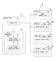
- FIG. 2 is a block diagram illustrating a configuration of the robot 4 .
- the robot 4 includes a control unit 100 , a voice generating unit 110 , a head control unit 120 , an arm control unit 130 L, an arm control unit 130 R, a voice output unit 140 L, a voice output unit 140 R, a leg control unit 150 L, and a leg control unit 150 R.
- the control unit 100 is a driving control unit.
- the voice generating unit 110 is a voice generating unit.
- the voice output unit 140 L and the voice output unit 140 R are voice output units.
- the head control unit 120 is disposed in the head unit 42 or at an upper portion of the body unit 41 .
- the head control unit 120 the bearing (a rotation movement) of the head unit 42 around the pitch axis, which is in a vertical plane, based on a control signal from the control unit 100 .
- the head control unit 120 controls the bearing (a rotation movement) of the head unit 42 around the yaw axis, which is in a horizontal plane, based on the control signal from the control unit 100 .
- a bearing of the head unit 42 to the body unit 41 can be changed in the direction of the pitch axis and in the direction of the yaw axis. Then, the head unit 42 can be shaken from side to side and up and down.
- the leg control unit 150 L is disposed in the leg unit 43 L.
- the leg control unit 150 R is disposed in the leg unit 43 R.
- the leg control unit 150 L and the leg control unit 150 R control an operation such as a two-legged walking based on the control signal from the control unit 100 .
- the arm control unit 130 L is disposed in the arm unit 44 L.
- the arm control unit 130 R is disposed in the arm unit 44 R.
- the arm control unit 130 L and the arm control unit 130 R control an operation of the arm unit 44 L and the arm unit 44 R during the two-legged walking based on the control signal from the control unit 100 .
- the control unit 100 is disposed in the storage unit 45 .
- the control unit 100 outputs the control signal to the head control unit 120 , the leg control unit 150 L, the leg control unit 150 R, the arm control unit 130 L, and the arm control unit 130 R, and controls the operation of the head unit 42 , the leg unit 43 L, the leg unit 43 R, the arm unit 44 L, and the arm unit 44 R.
- the control unit 100 outputs information, which represents the bearing of the head unit 42 to the body unit 41 , to the voice generating unit 110 .
- the information that represents the bearing of the head unit 42 to the body unit 41 is referred to as head unit bearing information.
- control unit 100 If the control unit 100 outputs the information, which represents the bearing of the head unit 42 to the body unit 41 after a change of the bearing or a control by the control unit 100 , to the head control unit 120 as control information, then the control information is output to the voice generating unit 110 as the head unit bearing information. If the control unit 100 outputs the information, which represents a variation of the bearing of the head unit 42 to the body unit 41 between the present condition and the condition after the change of the bearing or the control by the control unit 100 , to the head control unit 120 as control information, then the bearing of the head unit 42 to the body unit 41 after the change of the bearing or the control by the control unit 100 is calculated, and the result of the calculation is output to the voice generating unit 110 as the head unit bearing information.
- the voice generating unit 110 is disposed in the storage unit 45 and includes a voice signal generating unit 112 and a voice signal correction unit 114 .
- the voice signal generating unit 112 generates a voice signal corresponding to a prescribed voice.
- the voice signal generating unit 112 outputs the voice signal, which has been generated, to the voice signal correction unit 114 .
- the prescribed voice is such as the voice corresponding to a language that is designated from outside, for example, by an operator of the robot 4 , the voice corresponding to a result of a prescribed determination process that is selected based on an order from outside, and the voice corresponding to a detection result of various sensors that the robot 4 includes, for example, the sensor for detecting obstacles.
- the robot 4 can output the voice while moving the head unit 42 .
- the voice signal correction unit 114 receives the voice signal from the voice signal generating unit 112 .
- the voice signal correction unit 114 receives the head unit bearing information from the control unit 100 .
- the voice signal correction unit 114 corrects the voice signal, which has been received from the voice signal generating unit 112 , based on the head unit bearing information, which has been received from the control unit 100 .
- the voice signal correction unit 114 receives the head unit bearing information that includes an angle showing the bearing of the head unit 42 in the direction of the pitch axis and an angle showing the bearing of the head unit 42 in the direction of the yaw axis. Concerning the bearing of the head unit 42 in the direction of the pitch axis, the voice signal correction unit 114 corrects the voice signal, which has been received from the voice signal generating unit 112 , by using a vocal tract filter that is based on a vocal tract model. If the bearing of the head unit 42 varies in the direction of the pitch axis, then a shape of the vocal tract varies and a spectral envelope of the voice signal varies.
- the voice signal correction unit 114 corrects a left-right ratio of an output level of the voice signal that is output to the voice output unit 140 L and the voice output unit 140 R. If the bearing of the head unit 42 varies in the direction of the yaw axis, then the shape of the vocal tract does not change and adjusting the left-right ratio of the output level of the voice signal is sufficient.
- the vocal tract filter based on the vocal tract model, the left-right ratio of the output level of the voice signal, the correction based on the bearing of the head unit 42 in the direction of the pitch axis, and the correction based on the bearing of the head unit 42 in the direction of the yaw axis will be described below.
- the voice signal correction unit 114 outputs the voice signal that has been corrected or the voice signal from the voice signal generating unit 112 based on the head unit bearing information to the voice output unit 140 L and the voice output unit 140 R.
- the voice output unit 140 L and the voice output unit 140 R are disposed in the body unit 41 , as described above.
- the voice output unit 140 L and the voice output unit 140 R receives the voice signal that has been generated by the voice generating unit 110 to output a voice to the exterior.
- the voice signal has been generated by the voice signal generating unit 112 or corrected by the voice signal correction unit 114 .
- FIG. 3A , FIG. 3B and FIG. 3C are graphs explaining a content related to the correction by the voice signal correction unit 114 .
- FIG. 4 is a view explaining the correction by the voice signal correction unit 114 .
- the vocal tract filter is modeled as H( ⁇ p ), while ⁇ p is an angle of the head unit 42 in the direction of the pitch axis.
- the vocal tract filter H( ⁇ p ) is modeled by examining the voice of a man. Specifically, the head of an examinee is varied (by 10 degrees) between 50 degrees in a downward direction and 50 degrees in an upward direction, and each voice corresponding to each pitch angle ⁇ p is recorded having the same volume. The recording is performed in an anechoic room by using a close-talking microphone. As a result, the vocal tract filter H( ⁇ p ) is modeled.
- a sweep sound for 10 seconds that is made by producing a vowel “a” and has a basic frequency between 201 Hz and 523 Hz is recorded.
- the voice signal of the recorded voice is analyzed by using one-third octave-band analysis, and a sound pressure level ratio is calculated by using a point of each frequency band which pitch angle is 0 degrees as a reference point.
- the frequency band of the voice signal that is corrected based on the pitch angle ⁇ p is the frequency band in which the sound pressure level varies significantly based on the variation of the pitch angle ⁇ p .
- three frequency bands i.e. 500 Hz, between 800 Hz and 1,000 Hz, and between 2,500 Hz and 4,000 Hz are used in the frequency bands.
- the sound pressure level varies significantly based on the variation of the pitch angle ⁇ p as illustrated in FIG. 3A .
- the frequency band includes formants of almost all of the vowels.
- the horizontal axis of FIG. 3A represents the pitch angle ⁇ p and “Up” represents the upward direction and “Down” represents the downward direction.
- the vertical axis of FIG. 3A represents the sound pressure ratio corresponding to each pitch angle ⁇ p , which is calculated by using a point of each frequency band which pitch angle is 0 degrees as a reference point, that is, a gain g P i, ⁇ dB. As illustrated in FIG. 3A , the gain g P i, ⁇ is large when the examinee turns up and is small when the examinee turns down. If the examinee is a woman, the result is the same.
- FIG. 3B is a graph illustrating the sound pressure ratio based on the yaw angle ⁇ y .
- the horizontal axis of FIG. 3B represents the yaw angle ⁇ y and the unit is degree.
- a minus value of the yaw angle represents a right direction and a plus value of the yaw angle represents a left direction.
- 3B represents the ratio of the difference between the sound pressure level of the left channel and the sound pressure level of the right channel, which is calculated by using the difference between the sound pressure level of the left channel and the sound pressure of the right channel when the yaw angle is zero as the reference point, that is a gain g y L, ⁇ dB.
- FIG. 3B theoretical values and measured values are illustrated.
- the measured values which are more affected by the variation of the yaw angle ⁇ y , are used so that the variation of the direction of the face can be represented clearly.
- the measurement value illustrated in FIG. 3B can be acquired by measuring an impulse response of each microphone “mic.” in the anechoic room as illustrated in FIG. 3C .
- the yaw angle ⁇ y illustrated in FIG. 3C is set to 0 degrees at the center portion that is in a direction of a dashed line and the left direction represents a plus value of the yaw angle to be consistent with FIG. 3B .
- the voice signal correction unit 114 corrects the voice signal, which is received from the voice signal generating unit 112 , that is an input voice signal x(t) based on the pitch angle ⁇ p of the head unit 42 and then based on the yaw angle ⁇ y , of the head unit 42 .
- the voice signal correction unit 114 resolves the input voice signal x(t) into a ⁇ p -dependent element x i (t), which depends on the pitch angle ⁇ p , and a ⁇ p -independent element x NULL (t), which does not depend on the pitch angle ⁇ p .
- ‘i’ of the ⁇ p -dependent element x i (t) represents an index of the frequency band to be corrected.
- the input voice signal x 1 (t) is 500 Hz
- the input voice signal x 2 (t) is between 800 Hz and 1,000 Hz
- the input voice signal x 3 (t) is between 2,500 Hz and 4,000 Hz.
- the voice signal correction unit 114 calculates the ⁇ p -dependent element x i (t) based on the equation (1) and calculates the ⁇ p -independent element x NULL (t) based on the equation (2).
- x i ( t ) ( x*h i )( t ) (1)
- x NULL ( t ) ( x*h NULL )( t ) (2)
- h i represents a band pass filter that transmits the ⁇ p -dependent element x i (t) that includes the frequency bands of 500 Hz, between 800 Hz and 1,000 Hz, and between 2,500 Hz and 4,000 Hz.
- x NULL (t) is equal to the input voice signal x(t) minus the ⁇ p -dependent element x i (t).
- the gain of the frequency response corresponding to h NULL is zero at the frequency of 500 Hz, between 800 Hz and 1,000 Hz, and between 2,500 Hz and 4,000 Hz.
- the gain of the frequency response corresponding to h NULL is 1 at the center frequency of one-third octave-band except the frequency of 500 Hz, between 800 Hz and 1,000 Hz, and between 2,500 Hz and 4,000 Hz.
- the voice signal correction unit 114 calculates a gain g p i (t) of the i-th frequency band at the pitch angle ⁇ p (t) based on the equation (3).
- g i p ⁇ ( t ) g i , ⁇ m p ⁇ ( ⁇ m + 1 - ⁇ p ⁇ ( t ) ) + g i , ⁇ m + 1 p ⁇ ( ⁇ p ⁇ ( t ) - ⁇ m ) 10 ( 3 )
- the angle ⁇ m and the angle ⁇ m+1 are based on the pitch angle ⁇ p (t), which represents the bearing of the head unit 42 in the direction of the pitch axis, that are included in the head unit bearing information received from the control unit 100 .
- the angle ⁇ m and the angle ⁇ m+1 are calculated from the pitch angle ⁇ p (t) based on the equations (4) and (5).
- ⁇ m+1 ( ⁇ p ( t )/10 ⁇ +1) ⁇ 10
- ⁇ m ( ⁇ p ( t )/10 ⁇ ) ⁇ 10 (5)
- the voice signal correction unit 114 linearly-interpolates and amplifies a spectral envelope model corresponding to the gain of each pitch angle ⁇ p (t) of FIG. 3A with dB by 10 degrees as shown in the equations (4) and (5).
- the spectral envelope model is shown as A and B of FIG. 4 .
- the voice signal correction unit 114 amplifies the ⁇ p -dependent element x i (t) based on the equation (6).
- the voice signal correction unit 114 generates a stereo signal x ste from the monaural signal x p so as to correct the voice signal based on the yaw angle ⁇ y .
- the stereo signal x ste includes a left channel signal x L (t) and a right channel signal x R (t).
- the voice signal correction unit 114 calculates a gain g P L (t: ⁇ y (t)) of the left channel signal x L (t) corresponding to the yaw angle ⁇ y based on the equation (8). That is, the voice signal correction unit 114 corrects the output level ratio between the left channel signal x L (t) and the right channel signal x R (t) based on the bearing of the head unit 42 in the direction of the yaw axis.
- the voice signal correction unit 114 calculates a gain g P R (t: ⁇ y (t)) of the right channel signal x R (t) corresponding to the yaw angle ⁇ y (t).
- g R y ( t: ⁇ y ( t )) g L y ( t: ⁇ y ( t )) (11)
- the voice signal correction unit 114 linearly-interpolates and amplifies a spectral envelope model corresponding to the gain of each yaw angle ⁇ y (t) of FIG. 3C by 10 degrees as shown in the equations (9) and (10).
- the spectral envelope model is shown as C of FIG. 4 .
- the voice signal correction unit 114 amplifies the left channel signal x L (t) based on the equation (12) to generate a left channel output voice signal x′ L (t), and outputs the left channel output voice signal x′ L (t) to the voice output unit 140 L.
- the voice signal correction unit 114 amplifies the right channel signal x R (t) based on the equation (13) to generate a right channel output voice signal x′ R (t), and outputs the right channel output voice signal x′ R (t) to the voice output unit 140 R.
- the voice signal correction unit 114 corrects the left channel signal x L (t) and the right channel signal x R (t) to generate the left channel output voice signal x′ L (t) and the right channel output voice signal x′ R (t) based on the yaw angle ⁇ y (t) that represents the bearing of the head unit 42 in the direction of the yaw axis. That is, the voice signal correction unit 114 corrects the output level ratio of the left channel signal x L (t) and the right channel signal x R (t).
- the voice generated by the voice generating unit is not output from the voice output unit as it is.
- the voice generated by the voice generating unit is corrected based on the bearing of the movable unit and then output from the voice output unit. Therefore, the robot can output a natural sounding voice, which does not seem strange to people, based on the bearing of the movable unit.
- the voice is varied by imitating the variation of the voice of a man.
- the voice is varied based on the bearing of the head unit 42 not only in the vertical direction but also in the horizontal direction. Therefore, the robot can output a more natural sounding voice.
- the voice signal is corrected based on the bearing in the direction of the pitch axis by limiting the frequency of the correction target to a prescribed frequency based on an experimental result. Therefore, the amount of the calculation in performing the correction can be reduced effectively.
- the control unit 100 outputs the head unit bearing information to the voice signal correction unit 114 . That is, the voice signal correction unit 114 receives the head unit bearing information from the control unit 100 .
- the head unit bearing information represents the bearing of the head unit 42 to the body unit 41 .
- the voice signal correction unit 114 refers to the head unit bearing information when correcting the voice signal. But the way of the voice signal correction unit 114 receiving the head unit bearing information is not limited to the above way.
- the robot 1 may include a measurement unit, which is not illustrated in the figure, that measures the bearing of the head unit 42 to the body unit 41 , and the voice signal correction unit 114 may use the measurement result of the measurement unit as the head unit bearing information.
- the voice signal correction unit 114 corrects the voice signal based on the head unit bearing information.
- the method of the voice signal correction unit 114 correcting the voice signal is not limited to the above described method.
- the voice signal correction unit 114 may correct the voice signal based on information including the bearing of the leg unit 43 L, the leg unit 43 R, the arm unit 44 L, and the arm unit 44 R to the body unit 41 .
- a program that executes various processing of the robot 4 in accordance with the preferred embodiment of the present invention may be stored in a computer-readable recording medium.
- a computer system may read and execute the program that is stored in the recording medium to perform the various processing described above in accordance with the robot 4 of the preferred embodiment of the present invention.
- the computer system may include an OS or hardware such as peripheral device etc.
- the computer system may employ a WWW (World Wide Web) system. With such an arrangement, the computer system includes a homepage providing circumstances or homepage display environment.
- the computer readable recording medium refers to a writable nonvolatile memory such as a flexible disk, a magneto-optical disk, a ROM, or a flash memory, a portable medium such as a CD-ROM, and a memory device such as a hard disk incorporated in a computer system.
- the “computer readable recording medium” includes a medium storing a program for a predetermined time period, such as a volatile memory (for example, dynamic random access memory (DRAM)) incorporated in the computer system which becomes a server or a client in a case where the program is transmitted via a network such as the Internet, or a communication line such as a telephone line.
- a volatile memory for example, dynamic random access memory (DRAM)
- DRAM dynamic random access memory
- the above-mentioned program may be transmitted from the computer system which stores the program in the memory device or the like via a transmission medium, or may be transmitted by a transmitted wave through the transmission medium to another computer system.
- the “transmission medium” for transmitting the program refers to a medium having a function for transmitting information like a network (communication network) such as the Internet, or a communication line (communication wire) such as a telephone line.
- the above-mentioned program may be a program for realizing part of the above-mentioned function.
- the bearing of the robot represents the attitude of the robot.
- the bearing of the movable unit is equal to the bearing of the robot.
Abstract
Description
x i(t)=(x*h i)(t) (1)
x NULL(t)=(x*h NULL)(t) (2)
θm+1=(└θp(t)/10┘+1)×10 (4)
θm=(└θp(t)/10┘)×10 (5)
θn+1=(└θy(t)/10┘+1)×10 (9)
θn=(└θy(t)/10┘)×10 (10)
g R y(t:θ y(t))=g L y(t:−θ y(t)) (11)
Claims (7)
Applications Claiming Priority (2)
| Application Number | Priority Date | Filing Date | Title |
|---|---|---|---|
| JP2010056265A JP5393544B2 (en) | 2010-03-12 | 2010-03-12 | Robot, robot control method and program |
| JP2010-056265 | 2010-03-12 |
Publications (2)
| Publication Number | Publication Date |
|---|---|
| US20110224977A1 US20110224977A1 (en) | 2011-09-15 |
| US8639511B2 true US8639511B2 (en) | 2014-01-28 |
Family
ID=44560789
Family Applications (1)
| Application Number | Title | Priority Date | Filing Date |
|---|---|---|---|
| US12/881,812 Active 2031-04-19 US8639511B2 (en) | 2010-03-12 | 2010-09-14 | Robot, method and program of correcting a robot voice in accordance with head movement |
Country Status (2)
| Country | Link |
|---|---|
| US (1) | US8639511B2 (en) |
| JP (1) | JP5393544B2 (en) |
Families Citing this family (2)
| Publication number | Priority date | Publication date | Assignee | Title |
|---|---|---|---|---|
| TW201434600A (en) * | 2013-03-01 | 2014-09-16 | Compal Electronics Inc | Robot for generating body motion corresponding to sound signal |
| JPWO2017051627A1 (en) * | 2015-09-24 | 2017-11-30 | シャープ株式会社 | Voice utterance device, voice utterance method and program |
Citations (12)
| Publication number | Priority date | Publication date | Assignee | Title |
|---|---|---|---|---|
| US4820232A (en) * | 1987-12-04 | 1989-04-11 | Iwaya Corporation | Voice making device for moving animal toy and moving animal toy using the voice making device |
| JP2002023775A (en) | 2000-06-02 | 2002-01-25 | Sony France Sa | Improvement of expressive power for voice synthesis |
| JP2002085858A (en) * | 2000-09-11 | 2002-03-26 | Asami Boeki Kk | Vocal toy |
| US20040127140A1 (en) * | 2002-08-15 | 2004-07-01 | Emily Kelly | Feature-altering toy |
| US20040153212A1 (en) * | 2002-09-02 | 2004-08-05 | Profio Ugo Di | Robot apparatus, and behavior controlling method for robot apparatus |
| WO2005076660A1 (en) | 2004-02-10 | 2005-08-18 | Mitsubishi Denki Engineering Kabushiki Kaisha | Mobile body with superdirectivity speaker |
| US20050215170A1 (en) * | 2004-03-24 | 2005-09-29 | Uncle Milton Industries, Inc. | Toy figure with interchangeable brain having associated voice responses |
| JP2005266671A (en) | 2004-03-22 | 2005-09-29 | Yamaha Corp | Robot and voice reproduction method |
| JP2006136963A (en) | 2004-11-11 | 2006-06-01 | Hitachi Ltd | Robot |
| US20060143006A1 (en) * | 2001-10-22 | 2006-06-29 | Yasuharu Asano | Speech recognition apparatus and speech recognition method |
| US20070150107A1 (en) * | 2005-12-12 | 2007-06-28 | Honda Motor Co., Ltd. | Legged mobile robot control system |
| JP2011167820A (en) * | 2010-02-22 | 2011-09-01 | Advanced Telecommunication Research Institute International | Head part action control information generating device |
-
2010
- 2010-03-12 JP JP2010056265A patent/JP5393544B2/en active Active
- 2010-09-14 US US12/881,812 patent/US8639511B2/en active Active
Patent Citations (12)
| Publication number | Priority date | Publication date | Assignee | Title |
|---|---|---|---|---|
| US4820232A (en) * | 1987-12-04 | 1989-04-11 | Iwaya Corporation | Voice making device for moving animal toy and moving animal toy using the voice making device |
| JP2002023775A (en) | 2000-06-02 | 2002-01-25 | Sony France Sa | Improvement of expressive power for voice synthesis |
| JP2002085858A (en) * | 2000-09-11 | 2002-03-26 | Asami Boeki Kk | Vocal toy |
| US20060143006A1 (en) * | 2001-10-22 | 2006-06-29 | Yasuharu Asano | Speech recognition apparatus and speech recognition method |
| US20040127140A1 (en) * | 2002-08-15 | 2004-07-01 | Emily Kelly | Feature-altering toy |
| US20040153212A1 (en) * | 2002-09-02 | 2004-08-05 | Profio Ugo Di | Robot apparatus, and behavior controlling method for robot apparatus |
| WO2005076660A1 (en) | 2004-02-10 | 2005-08-18 | Mitsubishi Denki Engineering Kabushiki Kaisha | Mobile body with superdirectivity speaker |
| JP2005266671A (en) | 2004-03-22 | 2005-09-29 | Yamaha Corp | Robot and voice reproduction method |
| US20050215170A1 (en) * | 2004-03-24 | 2005-09-29 | Uncle Milton Industries, Inc. | Toy figure with interchangeable brain having associated voice responses |
| JP2006136963A (en) | 2004-11-11 | 2006-06-01 | Hitachi Ltd | Robot |
| US20070150107A1 (en) * | 2005-12-12 | 2007-06-28 | Honda Motor Co., Ltd. | Legged mobile robot control system |
| JP2011167820A (en) * | 2010-02-22 | 2011-09-01 | Advanced Telecommunication Research Institute International | Head part action control information generating device |
Non-Patent Citations (4)
| Title |
|---|
| Japanese Notice of Allowance for Application No. 2010-056265, 8 pages, dated Sep. 17, 2013. |
| Miwa et al, "Development of a New Human-like Head Robot WE-4," Proceedings of the 2002 IEEE/RSJ Intl. Conference on Intelligent Robots and Systems, Oct. 2002, pp. 2443-2448. * |
| Otsuka et al, "Voice Quality Manipulation for Humanoid Robots Consistent with their Head Movements," 9th IEEE RAS International Conference on Human Robots, Dec. 7-10, 2009, Paris, France, pp. 405-410. * |
| Otsuka, Takuma, et al. "Voice-Awareness Control Consistent with Robot's Body Movements." RSJ 2009, Sep. 15, 2009, pp. 1-4. * |
Also Published As
| Publication number | Publication date |
|---|---|
| US20110224977A1 (en) | 2011-09-15 |
| JP5393544B2 (en) | 2014-01-22 |
| JP2011189439A (en) | 2011-09-29 |
Similar Documents
| Publication | Publication Date | Title |
|---|---|---|
| US9002024B2 (en) | Reverberation suppressing apparatus and reverberation suppressing method | |
| JP6140579B2 (en) | Sound processing apparatus, sound processing method, and sound processing program | |
| JP7419270B2 (en) | Wearable system speech processing | |
| US20070088544A1 (en) | Calibration based beamforming, non-linear adaptive filtering, and multi-sensor headset | |
| US20110190658A1 (en) | Portable sound source reproducing apparatus for testing hearing ability and method using the same | |
| US9478230B2 (en) | Speech processing apparatus, method, and program of reducing reverberation of speech signals | |
| US20130185068A1 (en) | Speech recognition device, speech recognition method and program | |
| US20150237456A1 (en) | Sound control apparatus, program, and control method | |
| US9240194B2 (en) | Voice quality conversion system, voice quality conversion device, voice quality conversion method, vocal tract information generation device, and vocal tract information generation method | |
| JP2017092732A (en) | Auditory supporting system and auditory supporting device | |
| US20110046511A1 (en) | Portable sound source playing apparatus for testing hearing ability and method of testing hearing ability using the apparatus | |
| US8639511B2 (en) | Robot, method and program of correcting a robot voice in accordance with head movement | |
| JP2532007B2 (en) | Hearing aid fitting device | |
| WO2020079918A1 (en) | Information processing device and information processing method | |
| JP4266370B2 (en) | Electronic musical instrument using attitude angle detection device and control method thereof | |
| JP6163924B2 (en) | Noise detection apparatus, noise detection method, noise reduction apparatus, noise reduction method, communication apparatus, and program. | |
| US20220262342A1 (en) | System and method for data augmentation and speech processing in dynamic acoustic environments | |
| Jo et al. | Development of auditory feedback system for violin playing robot | |
| WO1991011802A1 (en) | Time series association learning | |
| US20230070521A1 (en) | Training apparatus, method of the same and program | |
| JP5750636B2 (en) | Lip movement parameter generation device and computer program | |
| JP6782940B2 (en) | Tongue position / tongue habit judgment device, tongue position / tongue habit judgment method and program | |
| US11783826B2 (en) | System and method for data augmentation and speech processing in dynamic acoustic environments | |
| JP2014197072A (en) | Speech synthesis system and speech synthesis method | |
| Otsuka et al. | Voice-awareness control for a humanoid robot consistent with its body posture and movements |
Legal Events
| Date | Code | Title | Description |
|---|---|---|---|
| AS | Assignment |
Owner name: HONDA MOTOR CO., LTD., JAPAN Free format text: ASSIGNMENT OF ASSIGNORS INTEREST;ASSIGNORS:NAKADAI, KAZUHIRO;OTSUKA, TAKUMA;OKUNO, HIROSHI;REEL/FRAME:025449/0043 Effective date: 20100902 |
|
| FEPP | Fee payment procedure |
Free format text: PAYOR NUMBER ASSIGNED (ORIGINAL EVENT CODE: ASPN); ENTITY STATUS OF PATENT OWNER: LARGE ENTITY |
|
| STCF | Information on status: patent grant |
Free format text: PATENTED CASE |
|
| FPAY | Fee payment |
Year of fee payment: 4 |
|
| MAFP | Maintenance fee payment |
Free format text: PAYMENT OF MAINTENANCE FEE, 8TH YEAR, LARGE ENTITY (ORIGINAL EVENT CODE: M1552); ENTITY STATUS OF PATENT OWNER: LARGE ENTITY Year of fee payment: 8 |