US8635822B2 - Ventilated structural panels and method of construction with ventilated structural panels - Google Patents
Ventilated structural panels and method of construction with ventilated structural panels Download PDFInfo
- Publication number
- US8635822B2 US8635822B2 US13/817,851 US201113817851A US8635822B2 US 8635822 B2 US8635822 B2 US 8635822B2 US 201113817851 A US201113817851 A US 201113817851A US 8635822 B2 US8635822 B2 US 8635822B2
- Authority
- US
- United States
- Prior art keywords
- sheet
- panel
- edge
- spacing
- horizontal
- Prior art date
- Legal status (The legal status is an assumption and is not a legal conclusion. Google has not performed a legal analysis and makes no representation as to the accuracy of the status listed.)
- Expired - Fee Related
Links
- 238000010276 construction Methods 0.000 title claims description 13
- 238000000034 method Methods 0.000 title claims description 8
- 230000037361 pathway Effects 0.000 claims abstract description 45
- 238000009423 ventilation Methods 0.000 claims abstract description 34
- 239000011159 matrix material Substances 0.000 claims description 75
- 239000011120 plywood Substances 0.000 claims description 30
- 239000004033 plastic Substances 0.000 claims description 19
- 229920003023 plastic Polymers 0.000 claims description 19
- 239000002023 wood Substances 0.000 claims description 19
- 239000002131 composite material Substances 0.000 claims description 12
- 229910052751 metal Inorganic materials 0.000 claims description 4
- 239000002184 metal Substances 0.000 claims description 4
- 239000011094 fiberboard Substances 0.000 claims description 3
- 239000000463 material Substances 0.000 abstract description 30
- 239000010410 layer Substances 0.000 description 71
- 238000009408 flooring Methods 0.000 description 14
- 239000000853 adhesive Substances 0.000 description 10
- 230000001070 adhesive effect Effects 0.000 description 10
- 230000008901 benefit Effects 0.000 description 9
- 238000004519 manufacturing process Methods 0.000 description 9
- 239000002356 single layer Substances 0.000 description 9
- 238000009413 insulation Methods 0.000 description 8
- 230000013011 mating Effects 0.000 description 7
- 238000012546 transfer Methods 0.000 description 7
- 239000011152 fibreglass Substances 0.000 description 6
- 239000007787 solid Substances 0.000 description 5
- XLYOFNOQVPJJNP-UHFFFAOYSA-N water Substances O XLYOFNOQVPJJNP-UHFFFAOYSA-N 0.000 description 5
- -1 OSB Substances 0.000 description 4
- 239000001913 cellulose Substances 0.000 description 4
- 229920002678 cellulose Polymers 0.000 description 4
- 230000005465 channeling Effects 0.000 description 4
- 238000012216 screening Methods 0.000 description 4
- 238000012360 testing method Methods 0.000 description 4
- 241000238631 Hexapoda Species 0.000 description 3
- 239000004035 construction material Substances 0.000 description 3
- 238000009826 distribution Methods 0.000 description 3
- 210000002105 tongue Anatomy 0.000 description 3
- 229910052782 aluminium Inorganic materials 0.000 description 2
- XAGFODPZIPBFFR-UHFFFAOYSA-N aluminium Chemical compound [Al] XAGFODPZIPBFFR-UHFFFAOYSA-N 0.000 description 2
- 238000005452 bending Methods 0.000 description 2
- 210000003195 fascia Anatomy 0.000 description 2
- 239000006260 foam Substances 0.000 description 2
- 239000007789 gas Substances 0.000 description 2
- 238000007373 indentation Methods 0.000 description 2
- 230000008595 infiltration Effects 0.000 description 2
- 238000001764 infiltration Methods 0.000 description 2
- 230000003993 interaction Effects 0.000 description 2
- 239000007788 liquid Substances 0.000 description 2
- 238000005259 measurement Methods 0.000 description 2
- 239000011490 mineral wool Substances 0.000 description 2
- 125000006850 spacer group Chemical group 0.000 description 2
- 239000011493 spray foam Substances 0.000 description 2
- 125000000391 vinyl group Chemical group [H]C([*])=C([H])[H] 0.000 description 2
- 229920002554 vinyl polymer Polymers 0.000 description 2
- CWYNVVGOOAEACU-UHFFFAOYSA-N Fe2+ Chemical compound [Fe+2] CWYNVVGOOAEACU-UHFFFAOYSA-N 0.000 description 1
- 239000010426 asphalt Substances 0.000 description 1
- 230000004888 barrier function Effects 0.000 description 1
- 230000015572 biosynthetic process Effects 0.000 description 1
- 230000000903 blocking effect Effects 0.000 description 1
- 230000003139 buffering effect Effects 0.000 description 1
- 238000009435 building construction Methods 0.000 description 1
- 239000004566 building material Substances 0.000 description 1
- 239000011111 cardboard Substances 0.000 description 1
- 238000004891 communication Methods 0.000 description 1
- 239000004567 concrete Substances 0.000 description 1
- 239000000470 constituent Substances 0.000 description 1
- 238000007796 conventional method Methods 0.000 description 1
- 238000001816 cooling Methods 0.000 description 1
- 238000005520 cutting process Methods 0.000 description 1
- 230000007423 decrease Effects 0.000 description 1
- 230000001419 dependent effect Effects 0.000 description 1
- 238000013461 design Methods 0.000 description 1
- 230000003467 diminishing effect Effects 0.000 description 1
- 230000008030 elimination Effects 0.000 description 1
- 238000003379 elimination reaction Methods 0.000 description 1
- 238000001125 extrusion Methods 0.000 description 1
- 239000002657 fibrous material Substances 0.000 description 1
- 238000009415 formwork Methods 0.000 description 1
- 239000011121 hardwood Substances 0.000 description 1
- 238000009434 installation Methods 0.000 description 1
- 230000001788 irregular Effects 0.000 description 1
- 239000013521 mastic Substances 0.000 description 1
- 238000010297 mechanical methods and process Methods 0.000 description 1
- 238000002844 melting Methods 0.000 description 1
- 230000008018 melting Effects 0.000 description 1
- 150000002739 metals Chemical class 0.000 description 1
- 238000002156 mixing Methods 0.000 description 1
- 239000011368 organic material Substances 0.000 description 1
- 238000009428 plumbing Methods 0.000 description 1
- 230000008569 process Effects 0.000 description 1
- 230000002195 synergetic effect Effects 0.000 description 1
Images


Classifications
-
- E—FIXED CONSTRUCTIONS
- E04—BUILDING
- E04C—STRUCTURAL ELEMENTS; BUILDING MATERIALS
- E04C2/00—Building elements of relatively thin form for the construction of parts of buildings, e.g. sheet materials, slabs, or panels
- E04C2/30—Building elements of relatively thin form for the construction of parts of buildings, e.g. sheet materials, slabs, or panels characterised by the shape or structure
- E04C2/34—Building elements of relatively thin form for the construction of parts of buildings, e.g. sheet materials, slabs, or panels characterised by the shape or structure composed of two or more spaced sheet-like parts
-
- E—FIXED CONSTRUCTIONS
- E04—BUILDING
- E04D—ROOF COVERINGS; SKY-LIGHTS; GUTTERS; ROOF-WORKING TOOLS
- E04D13/00—Special arrangements or devices in connection with roof coverings; Protection against birds; Roof drainage; Sky-lights
- E04D13/17—Ventilation of roof coverings not otherwise provided for
-
- Y—GENERAL TAGGING OF NEW TECHNOLOGICAL DEVELOPMENTS; GENERAL TAGGING OF CROSS-SECTIONAL TECHNOLOGIES SPANNING OVER SEVERAL SECTIONS OF THE IPC; TECHNICAL SUBJECTS COVERED BY FORMER USPC CROSS-REFERENCE ART COLLECTIONS [XRACs] AND DIGESTS
- Y10—TECHNICAL SUBJECTS COVERED BY FORMER USPC
- Y10T—TECHNICAL SUBJECTS COVERED BY FORMER US CLASSIFICATION
- Y10T29/00—Metal working
- Y10T29/49—Method of mechanical manufacture
- Y10T29/49616—Structural member making
- Y10T29/49623—Static structure, e.g., a building component
- Y10T29/49629—Panel
-
- Y—GENERAL TAGGING OF NEW TECHNOLOGICAL DEVELOPMENTS; GENERAL TAGGING OF CROSS-SECTIONAL TECHNOLOGIES SPANNING OVER SEVERAL SECTIONS OF THE IPC; TECHNICAL SUBJECTS COVERED BY FORMER USPC CROSS-REFERENCE ART COLLECTIONS [XRACs] AND DIGESTS
- Y10—TECHNICAL SUBJECTS COVERED BY FORMER USPC
- Y10T—TECHNICAL SUBJECTS COVERED BY FORMER US CLASSIFICATION
- Y10T29/00—Metal working
- Y10T29/49—Method of mechanical manufacture
- Y10T29/49826—Assembling or joining
-
- Y—GENERAL TAGGING OF NEW TECHNOLOGICAL DEVELOPMENTS; GENERAL TAGGING OF CROSS-SECTIONAL TECHNOLOGIES SPANNING OVER SEVERAL SECTIONS OF THE IPC; TECHNICAL SUBJECTS COVERED BY FORMER USPC CROSS-REFERENCE ART COLLECTIONS [XRACs] AND DIGESTS
- Y10—TECHNICAL SUBJECTS COVERED BY FORMER USPC
- Y10T—TECHNICAL SUBJECTS COVERED BY FORMER US CLASSIFICATION
- Y10T428/00—Stock material or miscellaneous articles
- Y10T428/24—Structurally defined web or sheet [e.g., overall dimension, etc.]
- Y10T428/24058—Structurally defined web or sheet [e.g., overall dimension, etc.] including grain, strips, or filamentary elements in respective layers or components in angular relation
- Y10T428/24074—Strand or strand-portions
- Y10T428/24091—Strand or strand-portions with additional layer[s]
- Y10T428/24099—On each side of strands or strand-portions
-
- Y—GENERAL TAGGING OF NEW TECHNOLOGICAL DEVELOPMENTS; GENERAL TAGGING OF CROSS-SECTIONAL TECHNOLOGIES SPANNING OVER SEVERAL SECTIONS OF THE IPC; TECHNICAL SUBJECTS COVERED BY FORMER USPC CROSS-REFERENCE ART COLLECTIONS [XRACs] AND DIGESTS
- Y10—TECHNICAL SUBJECTS COVERED BY FORMER USPC
- Y10T—TECHNICAL SUBJECTS COVERED BY FORMER US CLASSIFICATION
- Y10T428/00—Stock material or miscellaneous articles
- Y10T428/24—Structurally defined web or sheet [e.g., overall dimension, etc.]
- Y10T428/24273—Structurally defined web or sheet [e.g., overall dimension, etc.] including aperture
- Y10T428/24322—Composite web or sheet
- Y10T428/24331—Composite web or sheet including nonapertured component
-
- Y—GENERAL TAGGING OF NEW TECHNOLOGICAL DEVELOPMENTS; GENERAL TAGGING OF CROSS-SECTIONAL TECHNOLOGIES SPANNING OVER SEVERAL SECTIONS OF THE IPC; TECHNICAL SUBJECTS COVERED BY FORMER USPC CROSS-REFERENCE ART COLLECTIONS [XRACs] AND DIGESTS
- Y10—TECHNICAL SUBJECTS COVERED BY FORMER USPC
- Y10T—TECHNICAL SUBJECTS COVERED BY FORMER US CLASSIFICATION
- Y10T428/00—Stock material or miscellaneous articles
- Y10T428/24—Structurally defined web or sheet [e.g., overall dimension, etc.]
- Y10T428/24744—Longitudinal or transverse tubular cavity or cell
Definitions
- Sheathing is an essential component of any residential or commercial structure and provides structural support for roofs, walls and floors, as well as providing a surface of sufficient thickness and strength for the attachment of roofing materials such as asphalt shingles and metal roofing, siding materials such as wood clapboards or vinyl siding and flooring finishes such as tile, wood, hardwood, laminates, vinyls or carpets and the like.
- Sheathing has traditionally been supplied in 4′ ⁇ 8′ sheets, made of plywood or OSB, which provide a desirable modular size that can be handled by one worker.
- the means of attachment depends on the function, thickness and strength requirements of the application and may include mechanical fasteners such as nails or staples and/or adhesives. Roofs, walls, and flooring use sheets of similar sizes, though varied thickness.
- Another object of the present invention is to provide a ventilated structural panel comprising a first sheet, having edges that define a horizontal axis with a first horizontal edge and a second horizontal edge, and vertical axis with a first vertical edge and a second vertical edge.
- the panel additionally comprises a second sheet being of substantially the same planar dimensions as the first sheet and having edges that define a horizontal axis and vertical axis, with a first horizontal edge and a second horizontal edge and a first vertical edge and a second vertical edge; the first and second sheet being parallel in plane and preferably matched in at least one of the vertical axis and the horizontal axis.
- a plurality of spacing structural elements fixedly attaches the first sheet to the second sheet, such that the strength of the combined panel is multiple times greater than the combined individual strength of the first and second sheet.
- the ventilated structural panel can be at least semi-permeable to the passage of gases and liquids and the first or bottom sheet of the panel could have one or more perforations.
- the invention is an interlocking construction panel of the same size and approximate weight of conventional sheathing products that incorporates integral ventilation into the structure.
- the invention may be used as a conventional sheathing and is attached with the same mechanical methods of nailing and/or adhesives. It is cut and fitted in the same manner. It interlocks to provide continuity of strength and ventilation.
- the panel is engineered such that it provides the same or superior strength of conventional methods of providing construction strength and ventilation, with fewer materials.
- the materials involved in the construction of the panel are relatively inexpensive and readily available.
- the panels facilitate the use of a wide variety of insulation possibilities without the need for special consideration for ventilation, since the ventilation is integral with the panels. This is useful for common fiberglass as well as blown products such as fiberglass, Rockwool, cellulose and other products. This is especially useful for the new high performance spray foam expanding insulations that are becoming popular because of their high energy efficient performance and ability to seal infiltration, as the foams can break, plug or destroy conventional foam, plastic, or cardboard ventilation products, or intrude into the seams.
- the panels could be combined with a multitude of construction materials and methods in the same way conventional sheathing is used today.
- the panels could be used with conventional soffit and ridge vents by cutting the sheathing on the panels for access to the ventilation cavity. Drip edges would have to have an extended leg to cover the side ventilation or it could be blocked with conventional trim.
- the panel may be constructed sheets of commonly available 4′ ⁇ 8′ sheathing of a thickness determined by structural and roof fastening requirements, but may preferably vary from 1 ⁇ 4′′ to 11 ⁇ 2′′ in thickness, and more preferably vary from 3 ⁇ 8′′ to 3 ⁇ 4′′ in thickness.
- the top and bottom sheets may also vary in thickness.
- the two sheets are attached to each other via the spacing structural elements, with adhesive and/or mechanical means such as nailing, stapling, screwing or machine impressed metal connections, so as to provide for the transfer of forces.
- the two sheets function as the top and bottom chords of a truss or “I” beam providing superior strength, load carrying capacity, and resistance to deflection (stiffness).
- rafter or stud or purloin spacing may be increased where these panels are used, which would reduce material requirements, allowing the elimination of rafters and trusses with the greater spacing.
- the spacing structural elements may protrude beyond two contiguous edges of the panel, and the spacing structural elements may be chamfered to enhance interlocking with adjacent panels.
- the spacing structural elements would likewise be indented on the two opposite contiguous edges.
- Another embodiment of the invention is a panel comprised of two sheets of the same size (i.e., same area, but perhaps different thicknesses) connected to each other with a matrix of crossed spacing structural elements such that the combined entity is one structural panel.
- the panel is the same size as conventional building sheathing, generally 4′ ⁇ 8′, but can be of any size or thickness.
- the sheets are connected so as to be are parallel in plane and matched in the vertical axis, one on top of the other, such that they can be used in place of traditional sheathing materials currently used in building construction such as plywood sheathing, OSB sheathing and other composite sheathing materials.
- the panel includes a first and a second 4′ ⁇ 8′ sheet of plywood, Oriented Strand Board (OSB), or a composite board of wood and/or plastic, each sheet having a thickness of 1 ⁇ 4′′ to 3 ⁇ 4′′ depending on the application.
- Roofs would usually consist of the two sheets measuring 1 ⁇ 4′′ to 5 ⁇ 8′′ in thickness, depending on strength and span requirements and shingle attachment requirements, and whether the shingles are attached by staples or nails.
- Wall sheathing sheet thickness would also be of 1 ⁇ 4′′ to 1 ⁇ 2′ thickness depending on strength requirements.
- the top wear layer of the flooring panel will usually have a 1 ⁇ 2′′ to 3 ⁇ 4′′ finish layer depending on strength requirements and floor covering.
- Blocks may be used as the as the spacing structural elements, spacing the sheets ideally 11 ⁇ 2′′ from each other.
- the spacing can vary depending on the application and ventilation requirements—more spacing not only enhances ventilation and potentially increases the strength of the assembly, but would also require closer spacing of the blocks or spacers. While panels constructed with blocks would not have the degree of added strength as panels constructed of elongated members (discussed below), panels constructed of blocks would potentially be less expensive, and provide sufficient increased strength for construction with conventional 16 or 24 inch spaced of stud, rafter, truss, or joist is used.
- the blocks are generally spaced from 1 to 12 times their own width apart horizontally and vertically. The specific spacing would depend on the sheet thickness and strength requirements. Blocks were found to only increase the strength of the panel, over the combined individual strength of the separate sheets comprising the panel, by approximately one half the amount of increase as panels utilizing rectangular shaped elongated members. But, using blocks does offer additional construction possibilities over rectangular elongated members due to the increased contagious space inside a panel offered by using blocks compared to using a matrix of elongated members.
- the blocks can be oriented on the same axis of the sheets or arranged on an angle of preferably 45°; but other orientations, such as 30° or 60°, are possible depending on the application. The angled orientation strengthens the plywood or OSB assembly.
- Another embodiment of the invention uses spacing structural elements consisting of a matrix of rectangular shaped elongated members, preferably comprised of wood members with a square cross section, arranged in layers, each layer oriented perpendicular to the next, and each layer interconnected to each adjacent layer or adjacent sheet with mechanical means and/or adhesives.
- the individual elongated members would ideally be of 3 ⁇ 4′′ ⁇ 3 ⁇ 4′′, but could be larger or smaller.
- the individual elongated members would ideally be long enough to stretch from one edge of a sheet to another—this required length varying depending on the orientation of the elongated member.
- each elongated member would be aligned in layers and spaced, parallel, apart from one another preferably between 1 to 18 times the thickness of the elongated member, or 3 ⁇ 4′′ to 13.5 inches for elongated members with cross sections measuring 3 ⁇ 4′′ ⁇ 3 ⁇ 4′′, and more preferably between 5 and 16 times the thickness of the elongated member, and most preferably between 8 and 12 times the thickness of the elongated member.
- each elongated member preferably measures between 0.25 and 1.50 inches in height and between 0.25 and 1.50 inches in width, more preferably measures between 0.5 and 1.0 inches in height and between 0.5 and 1.0 inches in width, and most preferably measures between 0.7 and 0.8 inches in height and between 0.7 and 0.8 inches in width.
- the matrix of elongated members could consist of two layers perpendicular to each other or of multiple successive perpendicular layers.
- the matrix can be attached to the sheets either parallel to the sheet axis or on an angle. If an angular orientation is used, the elongated members will be ideally oriented 45° to each axis of both sheets, but other orientations such as 30° or 60° are possible depending on the application.
- the length of the elongated members would be of a length that they stretched from a first edge of a first sheet, to a second edge of the first sheet.
- Chamfered elongated members would preferably measure the “edge to edge” length of a sheet, but would be shifted in the direction of the chamfered end.
- chamfered mating elongated members would measure 48 inches and 96 inches in an orientation parallel to the sheet axis, and chamfered mating elongated members with a 45° orientation would measure approximately 69 inches or 137 inches respectively at the greatest measurements.
- the indented end of an elongated member can have a concave face that will accept all or a portion of the chamfered end of a mating elongated member.
- the total length of the elongated member would preferably be extended by the length in which the chamfered end recesses within the concave portion of the indented end.
- the elongated members may initially be secured to the sheets at lengths greater then required, and then be trimmed to finished length at a later point in the manufacturing process.
- the spacing structural elements can also be constructed of elongated members comprised of a plurality of plywood veneers, each veneer being typically 1 ⁇ 8′′ thick.
- This plywood matrix would be built up by multiple layers of veneered elongated members, each veneered elongated member being ideally 1 ⁇ 2′′ to 3 ⁇ 4′′ thick and spaced from 1 ⁇ 2′′ to 4′′ apart.
- the plywood matrix would consist of a first layer of similarly shaped and parallel aligned veneered elongated members, followed by one or more additional layers laid perpendicular to the first and/or immediately preceding layer, until a multi-layer plywood matrix of desired thickness is assembled.
- the veneered elongated members would be attached with adhesives.
- the resulting plywood matrix can be attached to the sheets either parallel to the sheet axis or on an angle. If an angular orientation is used, the veneered elongated members will be ideally oriented 45° to each axis of both sheets, but other orientations such as 30° or 60° are possible.
- the length of the veneered elongated members would be similar to that of the non-veneered elongated members above depending, depending on the angle of the orientation of the members to the axis of the sheets, and whether or not the veneered elongated members were chamfered.
- the spacing structural elements can protrude on two contiguous edges and be chamfered to enhance interlocking with adjacent panels.
- the spacing structural elements can be similarly matingly indented on the two opposite contiguous edges.
- the extension is normally less than or equal to 1 inch and ideally between 1 ⁇ 2′′ to 3 ⁇ 4′′.
- the elongation and indentation may be modified to provide for both contiguous mating of adjacent panels and a spacing gap between adjacent panels of between 0.0625 inches and 0.25 inches.
- the elongated members length could be increased by, for example, 1 ⁇ 8 inch, or the indentation could be reduced by 1 ⁇ 8 inch, or both, such that the elongated members may mating abut, but the neighboring first and second sheets would be spaced between 0.0625 inches and 0.25 inches apart.
- the panels with all attributes herein described can also be manufactured similarly to plywood except that the two exterior sheets are instead separated by a plurality of elongated members that are spaced apart and, in layers, are laid on to one another perpendicular to each other to permit the passage of air and the transfer of forces.
- These elongated members function as the spacing structural elements.
- the number of elongated members can vary as can the thickness of the elongated members, the width of the elongated members, the spacing of the elongated members and the orientation of the elongated members, for instance, some may be oriented on an or arranged in the same axis of the sheets.
- the apparatus may include three layers of elongated members, with two layers perpendicular to one another and diagonally oriented to the axis of the sheets, and one layer perpendicular to an axis of the sheets.
- the apparatus may include three layers of elongated members, with two layers perpendicular to one another and each perpendicular to an axis of the sheets, and one layer diagonally oriented to the axes of the sheets.
- the apparatus may include four layers of elongated members, with two layers perpendicular to one another and each perpendicular to an axis of the sheets, and two layers perpendicular to one another and diagonally oriented to the axes of the sheets.
- the apparatus may include three or four layers of elongated members, with each layer oriented perpendicular to the next, and all layers either perpendicular to an axes of the sheets, or all layers diagonally oriented to the axes of the sheets.
- the individual sheets for each panel are spaced equally apart from each other in parallel planes and in the same vertical axis, ideally at a distance of 11 ⁇ 2 from each other, with a matrix of spacing structural elements or members arranged in a cross hatch pattern between the two sheets.
- the matrix of members would ideally consist of a first layer of elongated members, each parallel, coplanar, and spaced equally from one another, the first layer being perpendicular to a second layer of elongated members, each parallel, coplanar, and spaced equally from one another.
- Each elongated member would generally have a square cross section and would extend in length from one side of the panel to another.
- a layer of screening e.g., fiberglass, aluminum, plastic
- the elongated members are generally spaced apart from a neighboring elongated member in the same layer from 1 to 12 times their own width, more preferably 3 to 9 times their own width, and most preferably 5 to 7 times their own width. The specific spacing would depend on the sheet thickness and strength requirements.
- the top layer would preferably be laid in the long horizontal direction, and have a length of 96 inches, with a repeat of 55 ⁇ 8′′ for shingle attachment if using nails for shingles and the object is to nail into the elongated member.
- the panel faces could be stamped, painted, or otherwise visibly marked with the orientation of the underlying matrix for ease of use by the workman.
- the elongated members would usually be oriented perpendicular to one another on the same axis of the sheets but other orientations are possible depending on the application. Testing indicates that the perpendicular orientation significantly strengthens the plywood or OSB assembly more than any other orientation, allowing the use of thinner exterior sheets. Tests have demonstrated that a strength increase in bending stiffness for an assembly of two 1 ⁇ 4 inch sheets, with a perpendicular matrix of two layers of 3 ⁇ 4′′ ⁇ 3 ⁇ 4′′ elongated members spaced 5 inches apart, has a bending strength approximately 10 times greater than a single sheet of 1 ⁇ 2′′ of plywood alone.
- the elongated members of the matrix can consist of square members made of wood, wood composite, plastic, or similar material, arranged perpendicular or close to perpendicular for an offset matrix, and interconnected to each other with mechanical means and/or adhesives.
- the individual matrix members would ideally be 3 ⁇ 4′′ ⁇ 3 ⁇ 4′′ square, and long enough to extend beyond the panel edge.
- the size of the elongated members could be larger or smaller and long enough to complete the required matrix of the sheets, which depends on the orientation, and extend to or beyond one edge. Spacing would be 1 to 12 times the thickness of the elongated member or 3 ⁇ 4′′ to 9 inches.
- the matrix of “elongated members” could consist of two layers perpendicular to each other or multiple layers. The matrix can be attached to the sheets either parallel to the sheet axis or on an angle of 45°, but other orientations are possible depending on the application. In all cases, a provision is made so that the panels interconnect structurally.
- the elongated members may be indented preferably between 1 ⁇ 4′′ and 5 ⁇ 8′′ and more preferably between 3 ⁇ 8′′ and 1 ⁇ 2 on two contiguous sides, while the other two sides would be extended by between preferably 1 ⁇ 4′′ and 5 ⁇ 8′′ and more preferably between 3 ⁇ 8′′ and 1 ⁇ 2′′ with an end member. Additionally, the length of the elongated members could be between 1 ⁇ 4 and 3 ⁇ 4 longer than the sheet on two contiguous sides to machine a tongue and groove attachment.
- the spacing structural elements can protrude on two contiguous edges and may be chamfered to enhance interlocking with adjacent panels.
- the spacing structural elements would be similarly indented on the two opposite contiguous edges.
- the extension would normally be no more than 1 inch and would ideally be between 1 ⁇ 2′′ to 3 ⁇ 4′′.
- the one or both sheets can be manufactured from plastic materials. These plastic sheeted panels could be used for waterproof applications such as for roofing or basement wall applications, with one or both sheets providing a barrier to liquid water and/or water vapor. The joints would be waterproofed with an application of waterproof mastic or tape. The panels could be combined with a multitude of construction materials and methods in the same way conventional sheathing is used today. Further, a top sheet of one panel may be extended in length and attached such that it overlaps a top sheet of an abutting lower adjacent panel by approximately two to four inches.
- the panels could also be manufactured with a perforated bottom sheet to facilitate ventilation into the panel matrix.
- the perforations would ideally be round in shape, sized 1 ⁇ 4′′ to 1′′ in diameter, and arranged in a matrix that is ideally staggered from the adjacent holes with a spacing of 4 to 12 diameters in widths.
- a layer of screening e.g., fiberglass, aluminum, plastic
- the perforations allow for the exhausting of heat, gases, and moisture in attics and non-living spaces.
- the holes should be such that the panel can still transfer necessary tensile and compressive forces. Both solid and perforated panels can be used together in building assembly, such as a roof.
- the panels can facilitate the use of a wide variety of insulation possibilities without requiring special consideration for ventilation since the ventilation is integral with the panels. This is useful for common fiberglass as well as blown products such as fiberglass, Rockwool, cellulose and other products. This is especially useful for the new high performance spray foam expanding insulations that are becoming popular because of their high energy efficient performance and ability to seal infiltration.
- the panels can be used in both residential and commercial construction.
- the panels can be used both for on site installation and for factory built modular homes.
- the panels would be useful for manufactured homes and trailers.
- the exterior of one or both sheets could be marked with exterior lines showing the location of the interior elongated members.
- the exterior facing sheet could also be of waterproof construction and made of waterproof material, such as some form of plastic, providing for the exposed layer of roofing or wall covering.
- the top sheet could be sized larger than the bottom sheet such that a top sheet of a first panel would extend to overlap a top sheet of an adjacent, and preferably vertically lower, panel.
- a flooring system of the ventilated structural panels as described would have many benefits. Increased structural strength, spanning capability and reduced deflection, all of which would result in less materials needed for supports (joists or trusses or composite joists) and better performance in terms of strength and stiffness.
- a properly engineered panel could be used for flooring providing a plenum for air distribution providing warmed and cooled air to be distributed within the floor. The warmed air would be a desirable characteristic in bathrooms.
- a properly engineered panel could be used for flooring providing a plenum for electrical distribution where wires and data communication cables could be easily run.
- a properly engineered panel could be used for flooring to provide a plenum for radiant heat or forced hot air heat. In this case, one interior surface would generally receive a layer of reflecting material and the spacers would have to be mechanically connected.
- a properly engineered panel could be used for flooring providing a plenum for plumbing distribution where pipes, tubes and conduits of proper size could be run.
- a flooring system with this panel construction is naturally quieter than one sheet of sheathing, providing a nose buffer. This noise buffering benefit would also apply to walls and roofing.
- This panel offers three main simultaneous advantages of ventilation, ease of use, and significantly increased strength.
- these panels offer ventilation both through the panel sheets and between the panel sheets.
- the panels may remove moisture and gasses passing through an interior facing sheet, and exhaust them via the continuous air channel created between the sheets by the spacing structural elements.
- This air channel will be approximately the width and height of the combined width and height of any contiguous surface formed by the ventilated structural panels being attached contiguous with one another.
- Such a large air channel can provide for dramatically increased air flow over the interior facing sheet, and thus dramatically increased ventilation between the interior and exterior—even if only passively.
- a particular advantage this offers is for roofing situations in colder climates to assist in avoiding ice dams.
- a ventilated structural paneled roof provides for ventilation of moisture and gasses from the house, and allows a flow of cold air along the entire roof surface, in the interior of the panels, to prevent the formation of ice dams.
- a ventilated structural paneled roof allows for the entire roof to remain cold in the winter, preventing snow from melting and ice dams from forming. Any heat that migrates into the ventilation plenum is exhausted to the outdoors and does not melt the snow on the roof.
- ventilation of a wall surface provides the same benefits noted above. Ventilation in warm climates or during warm months can exhaust hot air from the attic space, extending the life of roofing materials and reducing cooling costs.
- the inventive panels can typically achieve ventilation of at least 1/50, when compared to free, unobstructed end area, greatly exceeding many code requirements.
- the structural connection between the two sheets of material interconnected with spacing structural elements with adhesive and or mechanical means to transfer shear forces provides that the entire entity becomes a synergistic structural panel with characteristics that exceed the strength of the individual parts.
- the top and bottom sheets act like the flanges on a beam or truss and provide better load carrying strength, increased span capability and less deflection than the individual sheets together.
- Preliminary tests indicate that an assembly of two 1 ⁇ 4 inch sheets of plywood spaced with 3 ⁇ 4 inch blocks is 4 times stronger than just one sheet of 1 ⁇ 2 inch plywood alone, and two 1 ⁇ 4 inch sheets of plywood spaced with a matrix of two 3 ⁇ 4 by 3 ⁇ 4′′ members can be 10 times stronger than just one sheet of 1 ⁇ 2 inch plywood alone.
- This extra strength can be used advantageously to increase the load capacity or the length of the unsupported span of the panel, which reduces the required number of underlying supporting rafters, studs, joists, trusses or purloins, and thus cost of building.
- the spacing structural elements material, size, arrangement, thickness, shape and orientation can vary with the application and be adapted to the specific need of the application.
- the plurality spacing structural elements may be arranged such that a number of linear pathways are created. Each pathway's dimensions are limited by the dimensions and arrangements of the spacing structural elements. Utilizing blocks, the pathways may measure in height the full distance separating the first and the second sheet; the width measurement is dependent on how far apart the blocks are spaced from one another. Utilizing two layers of elongated members, the height of the pathways will measure approximately one half of the distance that separates the two sheets. Like the blocks, the width of the pathways formed with elongated members will be equal to the distance separating two neighboring elongated members in the same layer. When the two layers of elongated members are arranged perpendicular to each other, the pathways will also be orthogonal. Each pathway allows air to move along each pathway unobstructed from at least one edge of the panel to at least one opposite edge of the panel.
- the spacing structural elements can protrude on two contiguous sides with chamfered edges.
- the extent of the protrusion could be matched by an indention of the spacing structural elements on the opposite contiguous two edges which would provide for interlocking of panels. This interlocking of panels would provide structural continuity, increasing structural integrity and minimizing discontinuous deflection and buckling.
- the panel offers significant advantages as to ease of use. Since the panel is assembled from readily available building materials, it is familiar to the designers, suppliers and trades in terms of size and weight. It can be cut, sized and attached in the same manner of conventional sheathing. No special tools or skills are needed. No special orientation is needed to ensure the continuity of ventilation, except that the interlocks should be maintained for increased structural integrity. Ventilation is maintained without any special considerations or the use of any special additional materials, except insect and moisture blocking at the exposed edges.
- the panels can also be constructed as two sheets separated by a single layer matrix as described in paragraph 28.
- the matrix members can consist of wood, plywood, OSB, medium-density fiberboard (MDF), other wood composites, plastic or other materials and shaped in a rectangular or most likely square profile and extending either the length in the longitudinal direction or the width in the perpendicular direction. Said matrix can be extended on two contiguous edges and chamfered and indented on the opposite two edges to facilitate interlocking as previously described.
- MDF medium-density fiberboard
- the members would be placed parallel to each other and fastened to both the top and bottom panels with adhesives and/or mechanical means.
- the spacing between members would be from 2 times the thickness an individual matrix member to 16 times the thickness, but ideally from 4 times to 12 times.
- the single layer panels could also have perforations as previously described.
- the perforations would ideally be round but could also be other shapes such as oblong, oval, square or rectangular or a combination of geometric shapes such as square with rounded corners.
- the single layer panels would be useful for wall sheathing applications where the strength of the perpendicular matrix may not be as important or for some flooring applications.
- the panels may be used for decorating concrete formwork.
- the orientation of the single layer matrix may be either longitudinal, lateral, or diagonal depending on the specific application.
- the panel may be comprised of simply one sheet of panel with a matrix of members, without a second sheet. It could be constructed of plywood, OSB, MDF or other materials such as plastic or other composite wood material.
- the matrix of structural spacing elements can also be manufactured integrally with the panels in either OSB or Plywood or other materials such as MDF, plastics or other wood composites.
- Integral raised members would serve as the matrix of elongated members.
- Two similar sheets may have integral elongated members formed longitudinally in a first sheet and laterally in a second sheet. The two sheets would then be joined together by adhesives and/or mechanical means, with the matrix members in contact with one another. The finished flat panel surface would be exposed on the top and bottom.
- An alternative arrangement would provide for the integral raised members to be formed at angles to the edges of each respective sheet.
- the integral raised members on the first sheet would be formed such that, when they are mated with the integral raised members on the second sheet, the integral raised members of the first sheet will be perpendicular to the integral raised members of the second sheet.
- plywood sheets for example, could be manufactured with a plurality of raised ridges or strips.
- the raised ridges or strips would function as the integral elongated members.
- Two sheets would then be attached to each other with adhesives and/or mechanical means via the plurality of integral elongated members, preferably with the integral elongated members of each sheet in perpendicular orientation to the other respective sheet.
- These panels could also be manufactured from OSB, medium density fiberboard, or other wood composite materials or plastics.
- These panels and the sheets and integral elongated members could be manufactured in multiple steps, or in a single step.
- the integral members could be added during the panel production, or material could be removed after production to leave the plurality of elongated members, or the sheet and members could be formed substantially simultaneously, including with a mold.
- the integral raised elongated members could be made during the panel manufacturing process with special tools, equipment, rollers, molds and other such means as necessary.
- the shape of the integral raised member could take many shapes depending on the tooling, rollers, presses, machinery and other factors, including flat or round tops, sharp or rounded edges, and flattened or rounded sides. They could have rounded chamfered corners with or without a flat top, they could have angled chamfered corners, they could be rectangular or square in shape.
- the integral raised members could be either manufactured simultaneously with the sheets or could be shaped by removing material after manufacturing a sheet of extra thickness, to accommodate the finished thickness and integral raised member.
- Applications of the panels utilizing integral structural spacing elements would include roofing, flooring, and siding for residential and commercial construction.
- the panels with integral matrices' could be manufactured out of Plywood, OSB, MDF or other similar material, including plastics.
- the panels with integral matrices' could also have perforations as previously described.
- the perforations would ideally be round but could also be other shapes such as oblong, oval, square or rectangular or a combination of geometric shapes such as square with rounded corners.
- a further embodiment utilizing integral structural spacing elements would utilize the first sheet utilizing structural spacing elements, and a second sheet without integral structural spacing elements.
- non-integral structural spacing elements can also be used to attach the second sheet to the integral structural spacing elements of the first sheet to the second sheet.
- a still further embodiment utilizing integral structural spacing elements would utilize both the first and the second sheet, each with integral structural spacing elements, being connected to one another via non-integral structural spacing elements.
- Yet another embodiment utilizing integral structural spacing elements involves manufacturing the panel such at that the location where the integral members of the first sheet contact the integral members of the second sheet, there is provided that at least one first integral member of the first sheet may enter into a recess of at least one second integral member of the second sheet.
- the recess in the at least one second integral member functioning as a notch for the at least one first integral member to be received into.
- the at least one first and at least one second integral member could also be adhesively and/or mechanically joined.
- the least one first integral member may also be provided with a recess in which the at least one second integral member may enter. It is envisioned that the notched recesses may be provided only on the integrated members of one sheet, could be provided on the integrated members on both sheets.
- the notches could be provided uniformly on every elongated member one or both sheets, or could be staggeredly provided at alternating locations and/or on alternating integrated members on one or both sheets. It is also envisioned that this notch/recess arrangement could similarly be employed with non-integrated member embodiments.
- This notch like interface between members of multiple layers of members may also be utilized for panels including non-integral structural spacing elements, such as those discussed above.
- edges of the sheets on any panels in this application may be shaped with tongues on two contiguous edges and corresponding groves on the remaining two contiguous edges for interlocking of multiple panels, and/or interlocked with the indented and overlapped spacing structural elements arrangement described in paragraphs above.
- spacing structural elements create unobstructed pathways for air to move through the panel, from at least one edge of the panel to at least one of an opposite and an adjacent edge of the panel.
- the height of the unobstructed pathways will normally be equal to the height of the members.
- the width of the pathways will normally be equal to the spacing between adjacent members of a common layer.
- the number of parallel unobstructed pathways created in the panel for air to move in any one direction will preferably range from between 1 and 30, more preferably between 2 and 25, even more preferably between 4 and 20, yet even more preferably between 5 and 19, and most preferably between 6 and 12. If the elongated members were spaced at approximately 16 inches on center, the pathways could be approximately 15 inches in width.
- the pathways could be approximately 23 inches in width.
- the structural spacing elements and in particular the elongated members, can be formed in specialized shapes to convey additional qualities to the structural spacing elements, and thus the panels.
- Some specialized shapes include non-perforated and perforated I-beam, truss, skip truss, honeycomb, and corrugated shaped engineered matrix members.
- a panel could be configured as a single sheet with a single layer of elongated members attached to the sheet, the elongated members arranged parallel with one another, and parallel with one axis of the panel and perpendicular to the other axis. That is, the elongate members could be arranged parallel to a long axis or a short axis of the sheet.
- a single layer of members as described in the first alternative, may be arranged between and connected to two sheets.
- a panel could be configured as at least a double layer of elongate members attached to a single sheet, with each layer of elongate members arranged perpendicular to each adjacent layer of elongate members, at least one layer arranged parallel to one of a long or a short axis of the single sheet, and the elongate members being attached to one another where the multiple layers of elongate members intersect.
- an at least double layer of elongate members, as described in the third alternative may be arranged between and connected to two sheets.
- the panels, and their constituent sheets and structural spacing elements can be constructed or made from porous or non-porous wood, cellulose or other organic material, composite, ferrous, metallic, plastic, or any other material that can be shaped into a flat sheets and/or the structural spacing elements.
- the top and bottom sheets and the structural spacing elements can each be of different materials and thicknesses.
- the top sheet can be waterproof and the bottom sheet can be perforated to facilitate ventilation.
- the panel typically has an empty volume of approximately 70%, but can range from 40% to 90%, or preferably from 50% to 80%, or more preferably from 65% to 75%, depending on sheet thickness and structural spacing element size, shape, and placement.
- the panels may have a clear, unobstructed airflow of approximately 30% of the area of the end of any panel assembly, but can range from 10% to 60%, or preferably from 20% to 50%, or more preferably from 25% to 40%.
- the clear, unobstructed airflow can be up to around 75%, but can range from 65% to 85%, or more preferably from 70% to 80% of the end area of the panel assembly.
- the clear unobstructed airflow on a panel with solid matrix members of a range from approximately 1/50 to 1/70 when comparing free, unobstructed end area with panel coverage. This depends on roof slope, matrix member size and spacing. Some building codes require ventilation of 1/300, and some codes are contemplating requiring or recommending ventilation of 1/150. The inventive panels could provide 6 to 12 times greater ventilation performance.
- FIG. 1 is an exploded depiction of an embodiment of the panel
- FIG. 2 is plan view of an embodiment of the panel
- FIG. 3 is a plan view of an embodiment of the panel depicting the indented space and protruding segments
- FIG. 4 is a close-up iso view of an embodiment of the panel, depicting the indented space, protruding segments, and chamfered edges;
- FIG. 5 is an iso view of the panel mounted on mounting elements
- FIG. 6 is an iso view of an embodiment of the panel utilizing plywood veneer as spacing structural elements, without showing the top sheet;
- FIG. 7 is an iso view of an embodiment of the panel where the spacing structural elements are aligned diagonally, without showing the top sheet;
- FIG. 8 is an iso view of an embodiment of the panel utilizing rectangular blocks as spacing structural elements, without showing the top sheet;
- FIG. 9 is an iso view of an embodiment of the panel utilizing circular blocks as spacing structural elements, without showing the top sheet;
- FIG. 10 is an iso view of an embodiment of the panel utilizing square blocks as spacing structural elements, without showing the top sheet;
- FIG. 11 is a close-up iso view of an embodiment of the panel, depicting the indented space, protruding segments, and chamfered edges;
- FIG. 12 is an iso view of an embodiment of the panel with perforations in one sheet, viewed from the underside;
- FIGS. 13A and 13B are side views of two roof arrangements constructed with the panels
- FIG. 14 is a sectional view of a roof arrangement constructed with the panels for an unoccupied attic;
- FIG. 15A is a sectional view of a roof arrangement constructed with the panels for an occupied attic;
- FIG. 15B is a sectional view of a roof arrangement constructed with the panels for an unoccupied attic space, where some of the panels are perforated;
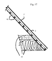
- FIG. 17 is a sectional view of a portion of a roof arrangement constructed using perforated and non-perforated panels;
- FIG. 18 is a sectional view of a house showing a wall, floor, and roof constructed using the panels;
- FIG. 19 is a sectional view of an insulated house showing a wall, floor, and roof constructed using the panels;
- FIG. 20 is an exploded view of the portion indicated as portion A in FIG. 19 ;
- FIGS. 20A and 20 B are iso-views of panels with a single layer of spacing structural elements, each having a portion of the top sheet cutaway to show detail;
- FIG. 21 is an iso-view of a panel with a sheet having integrated spacing structural elements
- FIG. 23 is an iso-view of a panel with two sheet, each having integrated elongated members with rectangular profiles;
- FIG. 24 is an iso-view of a panel with two sheets, each having integrated elongated members with curved profiles;
- FIG. 25 is an ISO view of a sheet having integrated elongated members and the plurality of perforations
- FIGS. 26A-26D are profile views of multiple examples of potential profiles of integrated elongated members.
- FIG. 27 is an iso views of a panel comprised of a single layer of nesting elongated members.
- FIG. 28 is an up close iso view of two elongated members with a notched attachment.
- FIGS. 29-31 are an up close perceptive views of panels using three different embodiments of specialized shaped engineered matrix members, where the top sheet in each panel is not shown;
- FIGS. 32-33 are close up perspective views of two additional embodiments of specialized shaped engineered matrix members.
- the panel 2 is comprised of a first sheet 4 and a second sheet 6 fixedly mated together via spacing structural elements 8 .
- the spacing structural elements 8 are comprised of a first layer 10 and a second layer 12 of rectangular shaped elongated members 14 , spaced apart from each other a predetermined spacing distance 16 .
- the arrangement of elongated members 14 in the first layer 10 is perpendicular to the arrangement of elongated members 14 in the second layer 12 , forming a matrix 17 of elongated members 14 .
- a first horizontal edge 18 and a second horizontal edge 20 of the first sheet 4 substantially align with a first horizontal edge 22 and a second horizontal edge 24 of the second sheet 6 , respectfully.
- a first vertical edge 26 and a second vertical edge 28 of the first sheet substantially align with a first vertical edge 30 and a second vertical edge 32 of the second sheet 6 , respectfully.
- the second sheet 6 though present each embodiment depicted, is not shown in FIGS. 2 , 3 and 6 - 10 below.
- the first 10 and the second layer 12 of elongated members 14 are indented a certain first distance 34 inward from the first horizontal edges 18 , 22 of the first and the second sheet 4 , 6 .
- the first 10 and the second layer 12 of elongated members 14 correspondingly overlap the second horizontal edges 20 , 24 of the first and the second sheet 4 , 6 by the same first distance 34 , creating first protruding segments 35 .
- the first 10 and the second layer 12 of elongated members 14 are indented a certain second distance 36 inward from the first vertical edges 26 , 30 of the first and the second sheet 4 , 6 .
- the first 10 and the second layer 12 of elongated members 14 correspondingly overlap the second vertical edges 28 , 32 of the first and the second sheet 4 , 6 by the same second distance 36 , creating second protruding segments 37 .
- first distance 34 of indent and overlap with respect to the horizontal edges can be of the same value as the second distance 36 of indent and overlap in the horizontal direction. It is to be noted that the indent and overlap have been exaggerated in FIG. 3 , to show detail.
- a portion of the first protruding segments 35 that overlap the second horizontal edges 20 , 24 of the first and the second sheet 4 , 6 have a chamfered edge 38 .
- These chamfered edges facilitate inserting the first protruding segments 35 of the first 10 and the second layer 12 of a first panel 2 into a second adjacent panel 2 , and specifically into a space provided by the inward indent of the elongated members 14 the first distance 34 from first horizontal edges 18 , 22 of the first 10 and the second layer 12 of the adjacent panel.
- the chamfer on the chamfered edge 38 would terminate between 1 ⁇ 8′′ and 3 ⁇ 8′′ from the second horizontal edges 20 , 24 of the first and the second sheet 4 , 6 , and preferably would terminate approximately 1 ⁇ 4′′ from the second horizontal edges 20 , 24 of the first and the second sheet 4 , 6 .
- a portion of the second protruding segments 37 that overlap the second vertical edges 28 , 32 of the first and the second sheet 4 , 6 have a chamfered edge 38 [not shown].
- These chamfered edges similarly facilitate inserting the second protruding segments 37 of the first 10 and the second layer 12 of a first panel 2 into a second adjacent panel 2 , and specifically into the space provided by the inward indent of the elongated members 14 the second distance 36 from the first vertical edges 26 , 30 of the first 10 and the second layer 12 of the adjacent panel.
- the chamfer on the chamfered edge 38 would terminate between 1 ⁇ 8′′ and 3 ⁇ 8′′ from the second vertical edges 28 , 32 of the first and the second sheet 4 , 6 , and preferably would terminate approximately 1 ⁇ 4′′ from the second vertical edges 28 , 32 of the first and the second sheet 4 , 6 .
- the panel 2 may be mounted onto mounting elements 40 such as roofing rafters or trusses, flooring joists, or wall studs, just as normal plywood or OSB board would be mounted—twelve inches on center. Because of the panels' increased strength, they may be mounted to mounting elements 40 spaced father apart than a plywood or OSB board of the same thickness as the sum of the thickness of the first and second sheet of the panel would require under similar conditions—including allowing the panels to be mounted on mounting elements 40 spaced sixteen, twenty four, thirty six, forty two, forty eight, and ninety six inches apart on center.
- mounting elements 40 such as roofing rafters or trusses, flooring joists, or wall studs, just as normal plywood or OSB board would be mounted—twelve inches on center. Because of the panels' increased strength, they may be mounted to mounting elements 40 spaced father apart than a plywood or OSB board of the same thickness as the sum of the thickness of the first and second sheet of the panel would require under similar conditions—including allowing the panels to be mounted on
- each elongated structural element 14 may be made up of a plurality of plywood veneer strips 42 , ranging from two to ten 1 ⁇ 8 inch plywood veneer strips 42 per elongated structural element 14 , and preferably six 1 ⁇ 8 inch plywood veneer strips 42 per elongated structural element 14 .
- the matrix 17 of elongated members 14 may be arranged diagonally with respect to the horizontal 18 , 20 , 22 , 24 and vertical 26 , 28 , 30 , 32 edges of the first and the second sheet 4 , 6 .
- the elongated members 14 of the first layer 10 may be arranged at an angle of between 30° and 60° with respect to the first horizontal edge 18 of the first sheet 4 , and preferably at an angle of 45° with respect to the first horizontal edge 18 of the first sheet 4 .
- the elongated members 14 of the second layer 12 may also be arranged at an angle of between 30° and 60° with respect to the first horizontal edge 18 of the first sheet 4 , and preferably at an angle of 45° with respect to the first horizontal edge 18 of the first sheet 4 .
- the spacing structural elements 8 may also be comprised of blocks 44 being preferably rectangular 46 , circular 48 , or square 50 in shape.
- blocks 44 are preferably rectangular 46 , circular 48 , or square 50 in shape.
- panels 2 utilizing blocks 44 as the spacing structural elements 8 increased the strength of a comparable plywood board by only half as much as panels 2 utilizing elongated members 14 as the spacing structural elements 8
- panels utilizing blocks 44 as the spacing structural elements 8 offer an increased assortment of paths that a pipe, tube, wire, or other insert 52 may be run through the panel 2 , especially if the insert has dimensions approaching one half the spacing between the first and second sheet 4 , 6 .
- the blocks 44 would also preferably be indented a first and second distance 34 , 36 , and similarly have first and second protruding segments 35 , 37 , correspondingly overlapping their respective edges the same first and second distances 34 , 36 .
- the blocks 44 could also be aligned diagonally with respect to the horizontal 18 , 20 , 22 , 24 and vertical 26 , 28 , 30 , 32 edges of the first and the second sheet 4 , 6 .
- the blocks 44 may be arranged at an angle of between 30° and 60° with respect to the first horizontal edge 18 of the first sheet 4 , and preferably at an angle of 45° with respect to the first horizontal edge 18 of the first sheet 4 .
- the protruding segments 35 , 37 of the blocks 44 would similarly be provided with a chamfered edge 38 , to assist in inserting the protruding segments 35 , 37 of the blocks of a first panel 2 into the space provided by the blocks 44 of an adjacent second panel 2 indented at least as much as the distance the protruding segments 35 , 37 protrude past the edge of the first and the second sheet 4 , 6 .
- FIG. 12 a perforated panel 2 ′ with a perforated first sheet 4 ′ is shown.
- the perforations 46 are arranged in a matrix type arrangement and facilitate the passage of air from the outside of the perforated panel 2 ′, through the perforated first sheet 4 ′, via the plurality of perforations 46 into the interior of the perforated panel 2 ′.
- the perforations 46 are through holes of between 1/16 inches and 11 ⁇ 2 inches in diameter, and preferably between 1 ⁇ 4 inches and 1 inch in diameter, and most preferably between 3 ⁇ 8 inches and 5 ⁇ 8 inches in diameter.
- the matrix arrangement may be staggered, with each hole spaced between 4 and 12 diameters from adjacent holes.
- a layer of screening 80 may be attached to the inner surface of the perforated first sheet 4 ′.
- the perforated panel 2 ′ is constructed in a similar manner to the non-perforated panel 2 , with the exception of perforating or using a perforated first sheet 4 ′, and the perforated panel 2 ′ may be used in the same manner as the non-perforated panel 2 .
- FIG. 13A shows a panel arrangement suited for unfinished attics and non-living spaces.
- the panels 2 , 2 ′ are arranged so that neither the first nor the second sheets 4 , 4 ′, 6 of the panels 2 , 2 ′ opposite the ridge meet, leaving an interior ridge gap 48 and an exterior ridge gap.
- the ridge will be capped with a ridge vent 52 .
- the bottommost terminal edges 56 of the panels 2 , 2 ′ will be include a screen 54 , insect block 58 , or other permeable occlusion, arranged to allow air passage into the interior of the panels 2 , 2 ′, but hinder insect entry.
- FIG. 13A shows a panel arrangement suited for unfinished attics and non-living spaces.
- the panels 2 , 2 ′ are arranged so that neither the first nor the second sheets 4 , 4 ′, 6 of the panels 2 , 2 ′ opposite the ridge meet, leaving an interior ridge gap 48 and an exterior ridge gap.
- the ridge will
- FIG. 13B shows a panel arrangement suited for finished attics and living spaces.
- the panels 2 , 2 ′ are arranged so that the first sheets 4 , 4 ′ of the panels 2 , 2 ′ opposite the ridge meet, forming a solid interior ridge 50 , but the second sheets 6 of the panels 2 , 2 ′ opposite the ridge meet do not meet, leaving an exterior ridge gap.
- the ridge will be capped with a ridge vent 52 , and the bottommost terminal edges 56 of the panels 2 , 2 ′ will be likewise permeably occluded.
- Panels 2 , 2 ′ are arranged on trusses and rafters 60 so as to leave an interior ridge gap 48 and an exterior ridge gap, as described in FIG. 13A .
- the ridge is capped by a ridge vent 52 .
- Warm, moist air 62 from the interior of the house is exhausted through the ridge vent, via the interior ridge gap 48 and exterior ridge gap.
- the panels are installed with the permeably occluded 54 , 58 terminal edges 56 adjacent to openings in soffits or lower fascia (not shown).
- Cooler air 64 enters through the permeably occluded 54 , 58 terminal edges 56 , travels through the interior of the panels 2 , 2 ′, absorbing heat from the first and the second sheets 4 , 4 ′, 6 and mixing with warm moist air entering through perforations 46 , and exits through the ridge vent 52 , via the exterior ridge gap.
- FIG. 15A a panel arrangement for an occupied attic or directly roofed living space is demonstrated.
- Panels 2 , 2 ′ are arranged on trusses and rafters 60 so as to leave an only an exterior ridge gap, as described in FIG. 13B .
- the ridge is capped by a ridge vent 52 .
- Warm, moist air 62 progresses from the interior of the house through insulation 65 and transfers its heat and moisture to the insulation 65 and first sheets 4 , 4 ′ of the panels 2 , 2 ′.
- the panels are installed with the permeably occluded 54 , 58 terminal edges 56 adjacent to openings in soffits or lower fascia (not shown).
- Cooler air 64 enters through the permeably occluded 54 , 58 terminal edges 56 , travels through the interior of the panels 2 , 2 ′, absorbing heat from the first and the second sheets 4 , 4 ′, 6 and exits warm air 62 through the ridge vent 52 , via the exterior ridge gap.
- the upper terminal edges 56 forming the upper ridge gaps in each embodiment may also be permeably occluded 54 , 58 .
- FIG. 15B a panel arrangement for an unoccupied attic space, using perforated panels is demonstrated.
- the perforated panels 2 ′ are arranged such that the perforated first sheet faces the interior of the building, allowing warm air 62 to directly enter into the interior of the panel matrix through the perforations 46 , from multiple locations in the attic space.
- the panels may be arranged either with or without an interior ridge gap 48 .
- a ridge vent 52 will be used to cap an exterior ridge gap (not shown) to allow the exhaust of warm air 64 out of the panel matrix, and in combination may be used with one or more gabled vents (not shown).
- the perforated panels 2 ′ and non-perforated panels 2 may be used in conjunction in a roofing construction arrangement.
- the perforated panels 2 ′ are arranged in the top one or more rows of the roof sheathing and the non-perforated panels 2 are arranged in the bottom one or more rows of roof sheathing.
- the inner first sheets 4 ′ of the upper rows of panels 2 ′ normally lack abutting insulation 65 , allowing warm moist air to more freely enter perforations 46 .
- the inner first sheets 4 of the lower rows of panels 2 normally have abutting insulation 65 , diminishing air transfer rates through perforations 46 , and therefore would normally have non-perforated first sheets 4 . It is to be appreciated that sheeting arrangements of all perforated panels 2 ′, all non-perforated panels 2 , or any combination of perforated and non-perforated panels 2 ′ 2 , would still fall in the scope of this invention.
- the panels may be likewise used in wall sheathing and flooring.
- a panel 2 , 2 ′ may be attached to a wall joist/wall stud 66 and floor joist 68 , in a similar manner as traditional sheeting materials.
- the terminal edges 56 will include permeable occlusions 54 , 58 .
- a terminal gap 74 facilitated by joist spacing elements 72 , here proximate to the ceiling joists 70 , provides a passageway for air to inter and exit the interior of the panels 2 , 2 ′.
- a panel 2 , 2 ′ is attached to an insulated 65 wall joist/wall stud and a floor joist 68 , with siding 76 attached to the exterior sheet of the panels 2 , 2 ′.
- the flooring panel 2 , 2 ′ contains a layer of screening 80 between the first layer 10 and the second layer 12 of elongated members 14 .
- Cool air 64 enters the panel 2 , 2 ′ interior by passing through a lower terminal gap 74 , facilitated by joist spacing elements 72 , then through the permeably occluded 54 , 58 lower terminal edge 56 , moves up through the interior of the panel 2 , 2 ′ absorbing heat and moisture from the first and the second sheets 4 , 4 ′, 6 , and exits warm air 62 through the permeably occluded 54 , 58 upper terminal edge 56 , and out an upper terminal gap 74 .
- the air flow may be channeled by one or more first channeling component 78 , and as shown in FIG. 20 , one ore more second channeling components 82 .
- the first and the second channeling components may be decorative as well as functional, and serve additionally as housing trim.
- FIG. 20 shows a close up of the upper section of FIG. 19 , indicated as portion A, showing in detail the upper terminal gap, and the first and the second channeling components 78 , 82 .
- FIGS. 21 and 22 A first sheet 4 A of a panel 2 A with integrated spacing structural elements 8 A is shown.
- the spacing structural elements 8 A may take the form of, for example, integrated blocks 44 A (not shown) or integrated elongated members 14 A.
- the integrated elongated members 14 A In panels 2 A employing integrated elongated members 14 A, the integrated elongated members 14 A generally run horizontally on a first sheet 4 A and will generally run vertically on a second sheet 6 A.
- the profiles of the integrated elongated members are generally either rectangular 100 , square 101 , or curved 102 , or some combination of each, depending upon the application requirements, each providing a plurality of parallel, unobstructed, contiguous pathways 5 .
- the integrated elongated members may have flat tops 104 , flat sides 106 , and angled edges 108 , and/or curved tops 110 , curved sides 112 , and rounded edges 114 or chamfered edges 116 . Additionally the sides maybe perpendicular where they intersect the top and/or the interior surface of the sheet 4 A, 6 A, or at a non-perpendicular angle.
- a first sheet 4 A′ and/or second sheet 6 A′ of panels 2 A′ with integrated elongated members 14 A may also possess perforations 46 A, and may be used in similar embodiments as those described in paragraphs above.
- a panel 2 A comprised of a first and a second sheet 4 A, 6 A, each having integrated elongated members 14 A.
- the integrated members 14 A on the first sheet 4 A are arranged parallel to the integrated members 14 A on the second sheet 6 A.
- This arrangement allows the integrated members 14 A on the first sheet 4 A to be nested within the spacing distance 16 separating the integrated members 14 A on the second sheet 6 A from one another, when the first and the second sheet 4 A, 6 A are brought together to form the panel 2 A.
- this allows the integrated members 14 A on the second sheet 6 A to be nested within the spacing distance 16 separating the integrated members 14 A on the first sheet 4 A from one another.
- the integrated members 14 A on the first sheet 4 A would attach directly to the interior surface of the second sheet 6 A in this embodiment.
- the parallel unobstructed continuous pathways 5 for air would be defined by the interior surface of the first and second sheets 4 A, 6 A and their respective integrated members 14 A, similar to a other single layer embodiments, as compared to being defined by the interior surface of one of the first sheet and second sheet 4 A, 6 A, and at least three separate elongated members 14 , 14 A, as in multiple layer embodiments.
- integrated elongated members 14 A of a first and second sheet 4 A, 6 A could be arranged parallel such that, instead of nesting within respective spacing distances 16 in the posing sheets 4 A, 6 A, as shown in FIG. 27 , the parallel elongated members 14 A of each sheet 4 A, 6 A could stack substantially directly on top of one another along the full length of the elongated members 14 A (not shown). This would create parallel unobstructed continuous pathways 5 for air that would be two elongated members 14 A high, and defined by for elongated members 14 A, two from each of the first and the second sheet 4 A, 6 A, and the interior surface of both the first sheet 4 A and the second sheet, 6 A.
- FIG. 28 a panel 2 is shown wherein the respective elongated members 14 of the first and the second sheets 4 A, 6 A interacts with one another at their point of attachment in a notch/recess fashion.
- a first elongated member 14 contacts a second elongated member 14 one or both of the first and the second elongated member 14 is provided with a notch 118 .
- this allows either the first or second elongated member 14 to recess into the notch 118 on the opposed elongated member 14 .
- both the first and second elongated members 14 are provided with opposing notches 118 at the point of interaction, this allows each elongated member to recess into the notches 118 provided on the opposed elongated member 14 . While this notch/recess arrangement creates a potentially stronger bond amongst the elongated members 14 and therefore the panel 2 as a whole, at the same time this decreases the size of the parallel, contiguous, unobstructed pathways 5 for air within the panel 2 .
- an elongated matrix member 14 is a stick or extrusion with a square or rectangular cross section and a length equal to a parallel axis of the sheet 4 , 6 to which it is attached.
- the elongated matrix members 14 are ideally 3 ⁇ 4′′ ⁇ 3 ⁇ 4′′ in cross section, but, as mentioned above, can be larger (2′′ or greater) or smaller (1 ⁇ 4′′ or smaller) as required for the application.
- the elongated matrix members 14 are preferably attached to at least one sheet 4 , 6 and to one another where multiple layers of elongated matrix members 14 intersect, in order to transfer shear stresses, though the elongated matrix members 14 may have one or more locations where they intersect that they are not attached, in order to increase flexibility of the overall panel, as may be required in certain situations.
- engineered matrix members 120 can be utilized and manufactured from a variety of materials, like organic, wood, cellulose or other fibrous materials, plastics, metals or other materials that can be shaped or extruded, and can be formed into the square or rectangular cross sectional shapes discussed previously, or formed into one of many specialized shapes.
- Specialized shaped engineered matrix members 120 will preferably have a first flat section 122 with a rectangular outer face, an opposed second flat section 124 with a rectangular outer face, and transverse section 126 connecting an inner face of the first flat section 122 to an inner face of the second flat section 124 .
- the outer face of at least one of the first and the second flat section 122 , 124 will preferably be attached to at least one of a sheet 4 , 6 and an outer face of a first or a second flat section 122 , 124 of an additional specialized shaped engineered matrix member 120 disposed in an adjacent layer.
- the range of shapes and structures of the specialized shaped engineered matrix members 120 will vary mainly based upon the design of the transverse section 126 .
- “I” beam shaped members 125 are formed by the first and second flat sections 122 , 124 of engineered matrix members 120 being joined by a relatively thin and elongate transverse section 126 .
- the thin elongate transverse section 126 and the inner faces of the first and the second flat sections 122 , 124 define two narrow channels, one on each side of the thin elongate transverse section. These narrow channels act to increase the size of parallel, contiguous, unobstructed pathways 5 for air to pass between two adjacent “I” beam shaped members 125 of a common layer, as compared to similarly spaced elongated members 14 with a square or rectangular cross section.
- the thin elongate transverse sections 126 in the “I” beam shaped members 125 may be solid or perforated.
- the perforated “I” beam shaped members 125 offer the benefit of enhanced cross ventilation performance and increase the interior cabling options of the panels, as the perforations 128 provide additional pathways 129 for air and/or cables to pass through the panel 2 , and through the very “I” beam shaped members 125 .
- the “I” beam shaped members 125 offer the benefit of being easily extruded and utilized in a panel 2 .
- “truss” shaped members 130 are constructed by the first and second flat sections 122 , 124 of engineered matrix members 120 being joined by a truss web 132 transverse section 126 .
- the truss web 132 is formed of a plurality of truss web supports 134 that can be both diagonal supports of the same or varying angles, and vertical supports.
- the truss web supports 134 will normally be of approximately an equal width as that of the first and the second flat sections 122 , 124 .
- the truss web 126 is comprised of a plurality of diagonal truss web supports 134 that form a continuous series of triangles down the length of the truss shaped member 130 . That is, except for terminal ends of the truss shaped members, at each intersection of a diagonal truss web support 134 with the inner face of the first and the second flat sections 122 , 124 , another diagonal truss will also intersect the same inner face of the first and the second flat sections 122 , 124 at an adjacent location. Such adjacent intersections form a triangulated parallel chord truss.
- the truss web supports 134 can be comprised of folded or formed material, and similar to the perforated “I” beam shaped members 125 , the truss shaped members 130 to facilitate additional air flow and additional pathways for running cables and pipes through the panels 2 , especially with the additional pathways diagonally and orthogonally through the specialized shaped engineered matrix members 120 .
- truss shaped members 130 in a second embodiment of truss shaped members 130 , the intersection of the diagonal truss web supports 134 with the inner face of the first and the second flat sections 122 , 124 can be spaced either a fixed or varying distance from one another.
- These “skip truss” shaped members 136 are similar to the truss shaped members 130 , but because they have less truss web supports 134 , they are less costly to manufacture and fabricate and offer increased size and angles of pathways through the panels 2 and the specialized shaped engineered matrix members 120 , while still retaining much of the superior strength qualities of the truss shaped members 130 .
- honeycomb shaped members 138 are constructed by the first and second flat sections 122 , 124 of engineered matrix members 120 being joined by a honeycomb web 140 transverse section 126 .
- the honeycomb web 140 is formed by a plurality of honeycomb or other repeating open geometric shapes connected to one another, and arranged such that an axis of opening B-B is disposed perpendicular to a long axis A-A.
- the honeycomb web 140 of the honeycomb shaped members 138 facilitates additional air flow and additional pathways 129 for running cables and pipes through the panels 2 , especially with the additional pathways diagonally and orthogonally through the specialized shaped engineered matrix members 120 .
- corrugated shaped members 142 are constructed by the first and second flat sections 122 , 124 of engineered matrix members 120 being joined by a corrugated or sinusoidal type curved web 144 transverse section 126 .
- the peaks and the troughs of the corrugated web 144 attach to the inner faces of the first and second flat sections 122 , and curving a path in-between.
- the curved shape of the corrugated web 144 provides a different profile and potentially wider pathways 129 for air flow and running cables, as compared to the truss shaped members 130 .
- the specialized shaped engineered matrix members 120 may be used in all situations as the rectangular shaped elongate members 14 .
- the specialized shaped engineered matrix members 120 may be formed in a separate process and later attached to the sheets 4 , 6 , or, similar to the integrated elongated members 14 A, the specialized shaped engineered matrix members 120 may be formed, in whole or part, together with the sheets 4 A, 6 A.
- Panels 2 may be constructed out of all non-engineered spacing structural elements 8 , all engineered matrix members 120 , or some combination of each.
Abstract
Description
Claims (19)
Priority Applications (1)
| Application Number | Priority Date | Filing Date | Title |
|---|---|---|---|
| US13/817,851 US8635822B2 (en) | 2010-08-24 | 2011-08-23 | Ventilated structural panels and method of construction with ventilated structural panels |
Applications Claiming Priority (7)
| Application Number | Priority Date | Filing Date | Title |
|---|---|---|---|
| US37633310P | 2010-08-24 | 2010-08-24 | |
| US12/987832 | 2011-01-10 | ||
| US12/987,832 US8490355B2 (en) | 2010-08-24 | 2011-01-10 | Ventilated structural panels and method of construction with ventilated structural panels |
| US13/016320 | 2011-01-28 | ||
| US13/016,320 US8534018B2 (en) | 2010-08-24 | 2011-01-28 | Ventilated structural panels and method of construction with ventilated structural panels |
| US13/817,851 US8635822B2 (en) | 2010-08-24 | 2011-08-23 | Ventilated structural panels and method of construction with ventilated structural panels |
| PCT/US2011/048786 WO2012027353A2 (en) | 2010-08-24 | 2011-08-23 | Ventilated structural panels and method of construction with ventilated structural panels |
Related Parent Applications (1)
| Application Number | Title | Priority Date | Filing Date |
|---|---|---|---|
| US13/016,320 Continuation-In-Part US8534018B2 (en) | 2010-08-24 | 2011-01-28 | Ventilated structural panels and method of construction with ventilated structural panels |
Publications (2)
| Publication Number | Publication Date |
|---|---|
| US20130145714A1 US20130145714A1 (en) | 2013-06-13 |
| US8635822B2 true US8635822B2 (en) | 2014-01-28 |
Family
ID=45695275
Family Applications (2)
| Application Number | Title | Priority Date | Filing Date |
|---|---|---|---|
| US13/016,320 Active 2031-07-18 US8534018B2 (en) | 2010-08-24 | 2011-01-28 | Ventilated structural panels and method of construction with ventilated structural panels |
| US13/817,851 Expired - Fee Related US8635822B2 (en) | 2010-08-24 | 2011-08-23 | Ventilated structural panels and method of construction with ventilated structural panels |
Family Applications Before (1)
| Application Number | Title | Priority Date | Filing Date |
|---|---|---|---|
| US13/016,320 Active 2031-07-18 US8534018B2 (en) | 2010-08-24 | 2011-01-28 | Ventilated structural panels and method of construction with ventilated structural panels |
Country Status (3)
| Country | Link |
|---|---|
| US (2) | US8534018B2 (en) |
| CA (1) | CA2796095A1 (en) |
| WO (1) | WO2012027353A2 (en) |
Cited By (3)
| Publication number | Priority date | Publication date | Assignee | Title |
|---|---|---|---|---|
| US20140093678A1 (en) * | 2010-08-24 | 2014-04-03 | James Walker | Ventilated structural panels and method of construction with ventilated structural panels |
| EP3045599A2 (en) | 2015-01-07 | 2016-07-20 | James Walker | Frameless construction using single and double plenum panels |
| US9604428B2 (en) | 2010-08-24 | 2017-03-28 | James Walker | Ventilated structural panels and method of construction with ventilated structural panels |
Families Citing this family (30)
| Publication number | Priority date | Publication date | Assignee | Title |
|---|---|---|---|---|
| SG148063A1 (en) * | 2007-05-18 | 2008-12-31 | James Lim Jee Keng | Composite cement panel |
| US8490355B2 (en) * | 2010-08-24 | 2013-07-23 | James Walker | Ventilated structural panels and method of construction with ventilated structural panels |
| US9050766B2 (en) | 2013-03-01 | 2015-06-09 | James Walker | Variations and methods of producing ventilated structural panels |
| US8615945B2 (en) * | 2010-08-24 | 2013-12-31 | James Walker | Ventilated structural panels and method of construction with ventilated structural panels |
| US8534018B2 (en) * | 2010-08-24 | 2013-09-17 | James Walker | Ventilated structural panels and method of construction with ventilated structural panels |
| US10822790B2 (en) * | 2010-08-24 | 2020-11-03 | Innovative Structural Building Products, Llc | Frameless construction using single and double plenum panels |
| CA2772874A1 (en) | 2011-04-21 | 2012-10-21 | Certainteed Corporation | System, method and apparatus for thermal energy management in a roof |
| WO2012174408A2 (en) | 2011-06-17 | 2012-12-20 | Basf Se | Prefabricated wall assembly having an outer foam layer |
| WO2012174377A1 (en) | 2011-06-17 | 2012-12-20 | Basf Se | High performance wall assembly |
| CA2864703A1 (en) * | 2013-09-24 | 2015-03-24 | Husnu M. Kalkanoglu | System, method and apparatus for thermal energy management in a roof |
| US9394696B2 (en) * | 2014-02-14 | 2016-07-19 | Norwood Architecture, Inc. | System and method for a vented and water control siding, vented and water control sheathing and vented and water control trim-board |
| US9963887B2 (en) | 2014-02-14 | 2018-05-08 | Norwood Architecture, Inc. | System and method for a vented and water control siding, vented and water control sheathing and vented and water control trim-board |
| CA2973733C (en) | 2015-01-19 | 2023-07-25 | Basf Se | Wall assembly |
| WO2016118490A1 (en) | 2015-01-19 | 2016-07-28 | Basf Se | Wall assembly having a spacer |
| US9598891B2 (en) * | 2015-03-23 | 2017-03-21 | Jk Worldwide Enterprises Inc. | Thermal break for use in construction |
| US10787809B2 (en) * | 2015-03-23 | 2020-09-29 | Jk Worldwide Enterprises Inc. | Thermal break for use in construction |
| US9879414B2 (en) * | 2015-05-12 | 2018-01-30 | Power Solutions International, Inc. | Three dimensional structural frames and enclosures |
| US9797147B2 (en) * | 2015-07-08 | 2017-10-24 | Void Form Products, Inc. | Water proof construction unit |
| US10519673B2 (en) * | 2015-12-23 | 2019-12-31 | James Hardie Technology Limited | Building cladding and method for preparing same |
| US11035127B2 (en) | 2015-12-23 | 2021-06-15 | James Hardie Technology Limited | Building cladding compositions, systems, and methods for preparing and assembling same |
| US10145108B2 (en) | 2016-05-12 | 2018-12-04 | Aryan Twenty 5, LLC | Panel and method for fabricating, installing and utilizing a panel |
| US9725902B1 (en) * | 2016-05-12 | 2017-08-08 | Aryan Twenty 5, LLC | Panel and method for fabricating, installing and utilizing a panel |
| SE542245C2 (en) * | 2016-06-27 | 2020-03-24 | Ikea Supply Ag | Hollow board |
| FR3056997B1 (en) * | 2016-10-03 | 2021-09-17 | Leko France | CONSTRUCTIVE SYSTEM WITH CROSSED STRUCTURAL BLADES |
| WO2018225051A1 (en) * | 2017-06-06 | 2018-12-13 | Livni Yacov | Method for constructing ventilated exterior walls of buildings |
| AU2018305724B2 (en) * | 2017-07-22 | 2019-12-19 | Acefield Constructions PTY LTD | A modular prefabricated wall system and a method of assembly thereof |
| CA3151798A1 (en) * | 2018-08-21 | 2020-02-27 | John David Wright | Insulatable, insulative framework apparatus and methods of making and using same |
| WO2021026591A1 (en) * | 2019-08-09 | 2021-02-18 | Dragox Pty Ltd | Barrier and panel thereof |
| US11680403B2 (en) | 2020-09-21 | 2023-06-20 | Amp Ip Llc | Multi-purpose structural panels and systems for assembling structures |
| JP7317305B1 (en) | 2022-08-19 | 2023-07-31 | 株式会社ケー・エス・ティー | Waterproof ventilation materials and waterproof ventilation building materials |
Citations (190)
| Publication number | Priority date | Publication date | Assignee | Title |
|---|---|---|---|---|
| US1086031A (en) | 1909-02-08 | 1914-02-03 | Lewis K Davis | Ventilated wall structure. |
| US1154254A (en) * | 1909-11-05 | 1915-09-21 | Universal Electric Welding Co | Sheet-metal panel-work. |
| US1928034A (en) * | 1930-11-24 | 1933-09-26 | Herbert H Schulstadt | Sound-absorbent material |
| US2220606A (en) * | 1938-04-19 | 1940-11-05 | M And M Wood Working Company | Wood panel |
| US2706164A (en) * | 1951-01-17 | 1955-04-12 | David E Hervey | Laminated panel |
| US2762472A (en) * | 1952-02-08 | 1956-09-11 | Pittsburgh Des Moines Company | Hollow sheet metal panels and method of making the sections from which such panels are made |
| US3024879A (en) * | 1959-04-09 | 1962-03-13 | Budd Co | Method of closing or joining integrated metal core panels and the structure produced |
| US3228162A (en) | 1962-09-17 | 1966-01-11 | Gregoire Engineering And Dev C | Building panel assembly |
| US3438164A (en) * | 1966-01-10 | 1969-04-15 | Elco Kunststoffe | Unit construction component |
| US3496052A (en) * | 1965-02-12 | 1970-02-17 | Us Plywood Corp | Grid core panel |
| US3537378A (en) * | 1969-02-04 | 1970-11-03 | George M Daly | Prefabricated metal insulated buildings |
| US3538668A (en) * | 1967-12-01 | 1970-11-10 | Howard A Anderson | Reinforced architectural shapes |
| US3662507A (en) | 1970-03-11 | 1972-05-16 | Arthur J Espeland | Preformed building wall construction |
| US3797180A (en) | 1972-07-17 | 1974-03-19 | H Grange | Ventilated roof construction |
| US3807116A (en) * | 1969-02-13 | 1974-04-30 | E Flynn | Building panel |
| US3886706A (en) * | 1970-12-21 | 1975-06-03 | William H Baker | Building sandwich panels |
| US3972164A (en) | 1974-03-11 | 1976-08-03 | Grange Howard L | Roof construction with inlet and outlet venting means |
| US4012882A (en) | 1972-04-19 | 1977-03-22 | Industrialised Building Systems Limited | Structural building panels |
| US4064300A (en) | 1975-07-16 | 1977-12-20 | Rolls-Royce Limited | Laminated materials |
| US4071194A (en) * | 1976-10-28 | 1978-01-31 | The United States Of America As Represented By The Secretary Of The Navy | Means for cooling exhaust nozzle sidewalls |
| US4084366A (en) * | 1975-11-14 | 1978-04-18 | Haworth Mfg., Inc. | Sound absorbing panel |
| US4093762A (en) * | 1974-04-30 | 1978-06-06 | John Kiefer | Method of making a hardcore honeycomb panel and honeycomb panel made thereby |
| US4285181A (en) * | 1977-12-15 | 1981-08-25 | Loghem Johannes J Van | Building planks and/or methods and/or apparatus for making the same |
| US4329827A (en) * | 1980-05-06 | 1982-05-18 | Masonite Ab | Roofing elements |
| SU941512A1 (en) | 1980-10-08 | 1982-07-07 | Специальное Конструкторско-Технологическое Бюро С Опытным Производством Стеклопластиков Института Механики Ан Усср | Laminated cellular panel |
| US4344266A (en) | 1978-11-09 | 1982-08-17 | Magnex Limited | Collapsible structure and method of building using such a structure |
| US4348442A (en) * | 1979-08-17 | 1982-09-07 | Figge Irving E | Structural panel |
| US4573304A (en) * | 1983-11-25 | 1986-03-04 | Donn Incorporated | Honeycomb floor panel and the like |
| US4635419A (en) | 1983-05-16 | 1987-01-13 | Forrest Joseph C | Vented roof construction |
| SU1308727A1 (en) | 1985-07-22 | 1987-05-07 | Вильнюсский Инженерно-Строительный Институт | Ventilated enclosure panel |
| US4663909A (en) * | 1985-03-12 | 1987-05-12 | Bridgestone Corporation | Outer heat insulating structure on a building roof |
| US4674249A (en) * | 1985-09-16 | 1987-06-23 | Carveth W Bennett Sr | Roofing and decking construction |
| US4676036A (en) * | 1985-05-01 | 1987-06-30 | Airtite, Inc. | Integrated raised flooring system |
| US4822660A (en) | 1987-06-02 | 1989-04-18 | Corning Glass Works | Lightweight ceramic structures and method |
| US4850166A (en) * | 1988-02-10 | 1989-07-25 | Taylor Gerald E | Ventilating system for roofing systems |
| US4852314A (en) | 1986-12-11 | 1989-08-01 | Moore Jr Thomas W | Prefabricated insulating and ventilating panel |
| US4860506A (en) * | 1987-03-06 | 1989-08-29 | Daiken Trade & Industry Co., Ltd. | Floor panel for floating floor |
| US4888927A (en) * | 1986-06-19 | 1989-12-26 | Daiken Trade & Industry Co., Ltd. | Floating floor |
| US4894974A (en) * | 1988-07-05 | 1990-01-23 | Walter J. Jaworski | Structural interlock frame system |
| USRE33220E (en) * | 1984-02-13 | 1990-05-22 | Interstitial Systems, Inc. | Modular combination floor support and electrical isolation system for use in building structures |
| US4937122A (en) * | 1989-03-28 | 1990-06-26 | Talbert William L | Insulated construction element |
| US4977714A (en) | 1988-09-12 | 1990-12-18 | Gregory Jr Stephen E | Roof ventilation baffle |
| US5022943A (en) * | 1989-08-25 | 1991-06-11 | Eften, Inc. | Method of making thermoformably shaped fibreboard sandwich structures |
| US5071688A (en) | 1989-03-17 | 1991-12-10 | Harry O. Hoffman | Building plywood product |
| US5098762A (en) | 1989-12-28 | 1992-03-24 | Asahi Woodtec Corporation | Plywood |
| US5099627A (en) | 1990-09-28 | 1992-03-31 | Benjamin Obdyke Incorporated | Ventilated roof construction and method |
| US5157892A (en) * | 1990-07-27 | 1992-10-27 | Ryther Ronald R | Structural interlocking joint system |
| US5180619A (en) * | 1989-12-04 | 1993-01-19 | Supracor Systems, Inc. | Perforated honeycomb |
| US5204161A (en) | 1991-06-03 | 1993-04-20 | Mcdonnell Douglas Corporation | Fabrication of panel structure |
| US5206067A (en) | 1992-01-28 | 1993-04-27 | Bonzo Kevin M | Landfill gas capping liner system |
| US5277953A (en) | 1991-11-11 | 1994-01-11 | Sotaro Tsuda | Laminated veneer lumber and decorative laminated sheet utilizing the same |
| US5299401A (en) * | 1993-02-03 | 1994-04-05 | Floyd Shelton | Athletic flooring system |
| US5366787A (en) * | 1991-06-03 | 1994-11-22 | Mcdonnell Douglas Corporation | Panel structure fabrication |
| US5369926A (en) | 1993-08-30 | 1994-12-06 | The Dow Chemical Company | Insulation board for plaza deck construction |
| US5377468A (en) | 1993-04-27 | 1995-01-03 | Hanover Architectural Products, Inc. | Aerodynamically stable roof paver system and ballast block therefor |
| US5396750A (en) * | 1993-11-08 | 1995-03-14 | Kleyn Die Engravers, Inc. | Modular building panel |
| US5433050A (en) | 1992-01-14 | 1995-07-18 | Atlas Roofing Corporation | Vented insulation panel with foamed spacer members |
| US5471806A (en) * | 1994-09-29 | 1995-12-05 | Rokhlin; Zinoviy A. | Construction panel with plurality of cells |
| US5473847A (en) | 1994-06-23 | 1995-12-12 | Old Reliable Wholesale Inc. | Ventilated insulated roofing system |
| US5487247A (en) | 1994-06-11 | 1996-01-30 | Pigg; Willard L. | Ventilated roof and wall structure |
| US5487930A (en) * | 1991-10-03 | 1996-01-30 | Tolo, Inc. | Three structure structural element with interlocking ribbing |
| US5493839A (en) * | 1995-02-21 | 1996-02-27 | Sax; Hilary H. | Structural building panel and panel system |
| US5527588A (en) | 1994-10-06 | 1996-06-18 | The United States Of America As Represented By The Administrator Of The National Aeronautics And Space Administration | Micro heat pipe panels and method for producing same |
| US5526625A (en) * | 1991-09-24 | 1996-06-18 | Building Solutions Pty Ltd. | Building panel and buildings using the panel |
| US5526621A (en) * | 1995-02-09 | 1996-06-18 | Shelton; Floyd | Ventilated athletic flooring system |
| US5543198A (en) * | 1988-07-25 | 1996-08-06 | Short Brothers Plc | Noise attenuation panel |
| US5561953A (en) | 1994-12-01 | 1996-10-08 | Rotter; Martin J. | Contoured ventilation system for metal roofs |
| US5561958A (en) | 1993-03-30 | 1996-10-08 | Neurones Of Zone Industrielle | Dynamic-insulation wall element for renewing air in buildings in order to make them more comfortable and cheaper |
| US5591511A (en) | 1993-03-19 | 1997-01-07 | Mcdonnell Douglas Corporation | Superplastically formed structure having a perforated skin |
| US5633053A (en) * | 1991-10-03 | 1997-05-27 | Lockshaw; James J. | Structural element with intermediate ribbing support |
| US5634315A (en) | 1994-03-02 | 1997-06-03 | Sogo Corporation | Buildings method of construction |
| US5640812A (en) * | 1991-06-07 | 1997-06-24 | Massachusetts Institute Of Technology | Roof panel design and single beam roof assembly |
| US5670220A (en) | 1991-09-10 | 1997-09-23 | Skoien; Ralph Warwick | Insulation batts |
| US5741571A (en) * | 1994-03-31 | 1998-04-21 | British Steel Plc | Double skin composite panels |
| US5761864A (en) * | 1994-08-31 | 1998-06-09 | Nonoshita; Tadamichi | Thermally insulated building and a building panel therefor |
| JPH1144011A (en) | 1997-07-25 | 1999-02-16 | Matsushita Electric Works Ltd | Ventilating floor panel and ventilation construction using the same |
| US5888610A (en) | 1995-06-08 | 1999-03-30 | Aerospatiale Societe Nationale Industrielle | Method for producing a panel or the like with structural and acoustic properties and panel obtained by said method |
| US5914175A (en) | 1997-08-25 | 1999-06-22 | Duraframe Window Shutter Systems Inc. | Composite panel and method |
| US5958551A (en) | 1995-08-31 | 1999-09-28 | Garcia-Ochoa; Jorge-Isaac | Structural element |
| US6017597A (en) | 1995-01-27 | 2000-01-25 | Minakami; Hiroyuki | Complex cell structure and method for producing the same |
| US6122892A (en) * | 1996-08-14 | 2000-09-26 | Societe Hispano-Suiza | Ventilated honeycomb cell sandwich panel and ventilation process for such a panel |
| US6134854A (en) * | 1998-12-18 | 2000-10-24 | Perstorp Ab | Glider bar for flooring system |
| US6171680B1 (en) | 1998-06-19 | 2001-01-09 | K2, Inc. | Composite sheathing material having high water vapor permeability |
| US6185895B1 (en) | 1998-12-24 | 2001-02-13 | Robert A. Rettew | Ventilating radiant barrier |
| US6189270B1 (en) * | 1997-05-30 | 2001-02-20 | Steelcase Development Inc. | Panel wall construction |
| US6269598B1 (en) * | 1999-01-08 | 2001-08-07 | Wintermantel, Brich | Flow channel structures, buildings incorporating flow channel structures, and methods of forming flow channel structures |
| US6286289B1 (en) * | 1999-12-08 | 2001-09-11 | John W. Powell | Multiple face sheet isogrid structures |
| US6415580B2 (en) | 1997-12-05 | 2002-07-09 | Leo V. Ojala | Insulated roof panel |
| US6449915B1 (en) | 1998-12-23 | 2002-09-17 | Time & Space Tech. Co., Ltd. | Inner wall finishing humidity control panel of cultural property storehouse |
| US6457288B2 (en) * | 2000-02-18 | 2002-10-01 | Sergio Zambelli | Prefabricated concrete panel for building floors in civil or industrial structures |
| US6591567B2 (en) * | 2000-12-09 | 2003-07-15 | West Virginia University | Lightweight fiber reinforced polymer composite modular panel |
| US6594964B2 (en) | 2000-08-15 | 2003-07-22 | Gilles Charland | Grooved construction beam |
| US6598366B2 (en) * | 2001-11-06 | 2003-07-29 | Juu Rong Hsieh | Modular raised floor system with cable-receiving groove network |
| US6609592B2 (en) * | 2000-06-30 | 2003-08-26 | Short Brothers Plc | Noise attenuation panel |
| US20030161994A1 (en) | 2002-02-22 | 2003-08-28 | Woo Je-Suk | Floor covering based on perforated PVC sheet |
| US20030167714A1 (en) | 2000-09-14 | 2003-09-11 | Adolf Jandl | Building |
| US6668504B2 (en) | 2002-04-11 | 2003-12-30 | Knight-Celotex, L.L.C. | Sound-deadened wall and wall panel for same |
| US20040101649A1 (en) * | 2001-04-26 | 2004-05-27 | Erwin Thoma | Pre-fabricated laminated wood element |
| US20040112007A1 (en) | 2002-12-12 | 2004-06-17 | Clarence Thibeau | Air gap spacer for use in building construction |
| US6780099B1 (en) | 2003-04-28 | 2004-08-24 | Richard W. Harper | Roof ventilation system |
| US20040177590A1 (en) * | 2003-03-14 | 2004-09-16 | Thomas Nudo | Composite structural panel and method |
| US20040197519A1 (en) * | 2001-08-24 | 2004-10-07 | Elzey Dana M. | Reversible shape memory multifunctional structural designs and method of using and making the same |
| US20040226238A1 (en) | 2003-04-15 | 2004-11-18 | Haapiainen Heikki Olavi | Methods and devices for building construction |
| US6852386B2 (en) | 2001-03-08 | 2005-02-08 | Norbord Inc. | Composite board with OSB faces |
| US20050053515A1 (en) * | 2003-09-10 | 2005-03-10 | Honeywell International Inc. | Cabin air quality system |
| US20050066619A1 (en) * | 2003-09-25 | 2005-03-31 | Mcdonald Mike | Building cladding panel |
| US20050072097A1 (en) * | 2002-07-18 | 2005-04-07 | Holloway Wynn Peter | Building panel |
| US20050144906A1 (en) * | 2002-11-15 | 2005-07-07 | Diversi-Plast Products, Inc. | Vented furring strip |
| US20050204695A1 (en) * | 2002-03-01 | 2005-09-22 | Paul Blazevic | Building panel and construction method |
| JP2006007694A (en) | 2004-06-29 | 2006-01-12 | Hideo Matsumura | Panel for building material and household effects |
| US20060005509A1 (en) | 2004-01-20 | 2006-01-12 | Yohnke Kenneth M | Building panel |
| US20060083894A1 (en) | 2004-10-20 | 2006-04-20 | Jan Vetrovec | Adhesive sheet |
| US20060131933A1 (en) * | 2002-12-11 | 2006-06-22 | Markus Boehm | Wall structure and method for the production thereof |
| US20060144013A1 (en) * | 2003-10-03 | 2006-07-06 | Cabot Corporation | Insulated panel and glazing system comprising the same |
| US7090911B2 (en) * | 2002-12-10 | 2006-08-15 | Gary Lascelles | Composite articles formed from sheets having interconnecting ridges |
| US20060218869A1 (en) | 2005-04-01 | 2006-10-05 | Billy Ellis | Thermal insulation for a building |
| US20060242920A1 (en) | 2002-11-11 | 2006-11-02 | Ari Griffner | Building made of wall hollow heated elements |
| US20060248855A1 (en) * | 2005-03-04 | 2006-11-09 | Olvey Douglas A | Foldably constructed force-resisting structures having interior vertical support ribs |
| US7134250B2 (en) * | 2000-01-13 | 2006-11-14 | Amalgamated Metal Industries Pty Ltd. | Building panels |
| US20060260265A1 (en) | 2005-05-19 | 2006-11-23 | Zatkulak Anthony D | Article and method for controlling moisture |
| US20060266001A1 (en) * | 2005-05-26 | 2006-11-30 | Joel Barker | Composite steel-wood floor structure |
| US7147741B2 (en) * | 2002-01-14 | 2006-12-12 | Peter Sing | Method of making a laminated structural member |
| US7150133B2 (en) * | 2002-05-08 | 2006-12-19 | Samuel R. Regina | Ventilated plastic blocks with film laminate |
| US20070034446A1 (en) * | 2005-08-10 | 2007-02-15 | William Proscia | Architecture for an acoustic liner |
| US20070095016A1 (en) * | 2005-10-12 | 2007-05-03 | Kabushiki Kaisha Kobe Seiko Sho (Kobe Steel, Ltd.) | Hollow panel and method for manufacturing same |
| US20070141304A1 (en) | 2005-12-21 | 2007-06-21 | Gaurav Agrawal | Perforated board formed from cementitious material and process and system for producing same |
| US20070169432A1 (en) * | 2003-12-03 | 2007-07-26 | Bridge Iain N | Panel structure |
| US20070204541A1 (en) | 2006-03-01 | 2007-09-06 | Rovshan Sade | External wall and roof systems |
| US20070209318A1 (en) * | 2006-03-10 | 2007-09-13 | Mccarthy Ronald | Modular panel assembly |
| US7288326B2 (en) * | 2002-05-30 | 2007-10-30 | University Of Virginia Patent Foundation | Active energy absorbing cellular metals and method of manufacturing and using the same |
| US20070266494A1 (en) * | 2006-05-08 | 2007-11-22 | Stryker Corporation | Air bearing pallet |
| US20070283639A1 (en) | 2006-06-12 | 2007-12-13 | Matt Kortuem | Cathedral ceiling vent baffle and method of installation |
| US20080028704A1 (en) | 2004-07-08 | 2008-02-07 | John Cooper | Vented roof and wall system |
| US20080034690A1 (en) * | 2006-08-11 | 2008-02-14 | Gartz Mark R | Underlayment with improved drainage |
| US20080163582A1 (en) * | 2004-02-27 | 2008-07-10 | James Hardie International Finance B.V. | Batten Mounting Water Management System |
| US20080202066A1 (en) * | 2007-02-09 | 2008-08-28 | Alcan Rhenalu | Metal composite panel and method of manufacture |
| US20090038262A1 (en) * | 2007-08-08 | 2009-02-12 | Marschke Carl R | Building Wall Panels of Hollow Core Construction |
| US20090044484A1 (en) * | 2005-02-04 | 2009-02-19 | Johann Berger | Building Board, Building Element or the Like |
| USD589171S1 (en) | 2007-03-21 | 2009-03-24 | James Hardie International Finance B.V. | Building element |
| US20090090083A1 (en) | 2007-10-05 | 2009-04-09 | Dagher Habib J | Roofing panel assembly |
| US7536835B2 (en) | 2005-04-13 | 2009-05-26 | Schlüter-Systems Kg | Floor construction covered with ceramic tiles |
| US20090183450A1 (en) * | 2006-05-15 | 2009-07-23 | Chen-Yin Lu | Assembly type wall structure |
| US20090277113A1 (en) | 2008-05-09 | 2009-11-12 | Thermapan Structural Insulating Panels Inc. | Structural insulating panel and flat roof structure employing same |
| US7651751B2 (en) | 2003-02-14 | 2010-01-26 | Kronotec Ag | Building board |
| US7669384B2 (en) * | 2005-07-20 | 2010-03-02 | Kobe Steel, Ltd. | Extruded hollow aluminum alloy panel and method for producing the same |
| US20100101171A1 (en) * | 2007-05-25 | 2010-04-29 | George Charles Clifton | Panels |
| US7722112B2 (en) | 2006-09-27 | 2010-05-25 | Wabash National, L.P. | Composite panel for a trailer wall |
| US20100146884A1 (en) * | 2008-12-17 | 2010-06-17 | Chen-Yin Lu | Combined wall panel |
| US7743884B2 (en) * | 2007-12-17 | 2010-06-29 | Airbus Deutschland Gmbh | Sandwich panel for sound absorption |
| US20100186305A1 (en) | 2009-01-23 | 2010-07-29 | Ram Enterprises | Smart panel |
| US20100189953A1 (en) * | 2007-05-18 | 2010-07-29 | Jee Keng James Lim | Composite cement panel |
| US7766280B2 (en) * | 2007-05-29 | 2010-08-03 | United Technologies Corporation | Integral suction device with acoustic panel |
| US7810296B1 (en) | 2007-05-03 | 2010-10-12 | Blendi Turku | Sheathing assembly and method of sheathing a roofing structure |
| US20100257795A1 (en) * | 2007-10-15 | 2010-10-14 | Pagliasotti Robert R | Building-integrated system for capturing and harvesting the energy from environmental wind |
| US20100279065A1 (en) | 2007-12-12 | 2010-11-04 | Ewald Dörken Ag | Vapor-permeable laminate |
| US20100300026A1 (en) * | 2007-05-11 | 2010-12-02 | Angelo Candiracci | Panel for making a building construction and method of making such panel |
| US20100300645A1 (en) * | 2009-05-28 | 2010-12-02 | Michael Glover | Building energy system |
| US20100325991A1 (en) * | 2009-05-22 | 2010-12-30 | Stephen John Trower | Building panel |
| US20100325990A1 (en) | 2009-05-22 | 2010-12-30 | Thermapan Industries Inc. | Structural flooring panel and floor structure incorporating the same |
| US20110030300A1 (en) | 2009-08-10 | 2011-02-10 | Liu David C | Floor And Tile With Padding |
| US20110047932A1 (en) * | 2009-08-31 | 2011-03-03 | Fleming Iii Joseph C | Building panel having plant-imitating structural core |
| US20110072746A1 (en) * | 2007-10-05 | 2011-03-31 | University Of Maine System Board Of Trustees | Interlocking roofing panel system |
| US20110162299A1 (en) * | 2008-05-23 | 2011-07-07 | Atma Engineering S.N.C. Di Azzolini Silvana | Modular unit for creating load-bearing structures, for use as a construction and/or support for a solar carpet |
| US8043690B2 (en) * | 2008-04-21 | 2011-10-25 | The Boeing Company | Exhaust washed structure and associated composite structure and method of fabrication |
| US20110265407A1 (en) * | 2010-04-29 | 2011-11-03 | Building Materials Investment Corporation | Above deck roofing ventilation system |
| US8052377B2 (en) * | 2006-11-15 | 2011-11-08 | Rolls-Royce Plc. | Cowling arrangement |
| US20110272034A1 (en) * | 2006-04-11 | 2011-11-10 | Fex Jr James Patrick | Method and apparatus to utilize wind energy within a structure |
| US20120017525A1 (en) | 2010-07-26 | 2012-01-26 | Michael David Knapp | Interlocking Building Panel |
| US20120047839A1 (en) | 2010-08-24 | 2012-03-01 | James Walker | Ventilated structural panels and method of construction with ventilated structural panels |
| US20120047844A1 (en) | 2010-08-24 | 2012-03-01 | James Walker | Ventilated Structural Panels and Method of Construction with Ventilated Structural Panels |
| US20120090265A1 (en) * | 2010-10-19 | 2012-04-19 | The Boeing Company | Method for joining sandwich truss core panels and composite structures produced therefrom |
| US8176635B2 (en) * | 2006-10-27 | 2012-05-15 | University Of Virginia Patent Foundation | Manufacture of lattice truss structures from monolithic materials |
| US20120174518A1 (en) * | 2009-09-29 | 2012-07-12 | Elmere | Method for Producing a Building Having a Prefabricated Wood Framework, and Resulting Building |
| US20120186184A1 (en) * | 2011-01-25 | 2012-07-26 | Charles Arthur Mencio | Thermally Reflective Panel Assembly |
| US8273208B2 (en) | 2005-09-14 | 2012-09-25 | Intrinsix, Llc | Structural composite laminate, and process of making same |
| US8287984B2 (en) * | 2006-06-08 | 2012-10-16 | Loda S.A.R.L. | Roofing underlay screen |
| US20120285116A1 (en) | 2010-08-24 | 2012-11-15 | James Walker | Ventilated structural panels and method of construction with ventilated structural panels |
| US8343398B2 (en) * | 2007-07-30 | 2013-01-01 | Khatchik Chris Khatchikian | Panels and a method of making |
| US20130036692A1 (en) * | 2011-08-11 | 2013-02-14 | Mark A. Aspenson | Thermal energy venting system |
| US8387315B2 (en) * | 2010-11-29 | 2013-03-05 | Qatar Football Association | Microclimate cooling system for an indoor/outdoor stadium |
| US8407965B2 (en) * | 2009-10-30 | 2013-04-02 | Sergey Evgenyevich Dorozhkin | System and method for construction wall panels |
| US20130084424A1 (en) * | 2010-06-10 | 2013-04-04 | Italcementi S.P.A. | Composite panel based on cementitious mortar with properties of transparency |
| US20130091792A1 (en) * | 2011-10-14 | 2013-04-18 | Empire Technology Development Llc | Air exchanging thermally responsive wall panels and methods |
| US20130125487A1 (en) * | 2011-05-12 | 2013-05-23 | Ross Patrick POWER | Insulation and ventilation systems for building structures |
| US8453399B2 (en) * | 2002-03-13 | 2013-06-04 | Battens Plus, Inc. | Roof batten |
| US8464831B2 (en) * | 2009-09-17 | 2013-06-18 | Volvo Aero Corporation | Noise attenuation panel and a gas turbine component comprising a noise attenuation panel |
| US8512853B2 (en) * | 2007-07-31 | 2013-08-20 | The Boeing Company | Composite structure having reinforced core |
| US20130230690A1 (en) * | 2007-07-31 | 2013-09-05 | The Boeing Company | Composite Structure and Method of Making the Same |
| US8528184B2 (en) * | 2010-05-24 | 2013-09-10 | Mueller International, Llc | Method of creating and maintaining a sealed interface between a spigot and bell |
| US8530027B2 (en) * | 2010-12-15 | 2013-09-10 | The Boeing Company | Fibers with interlocking shapes |
Family Cites Families (1)
| Publication number | Priority date | Publication date | Assignee | Title |
|---|---|---|---|---|
| US5468184A (en) * | 1993-10-13 | 1995-11-21 | Collier; William R. | Air circulation system for enclosed structures |
-
2011
- 2011-01-28 US US13/016,320 patent/US8534018B2/en active Active
- 2011-08-23 US US13/817,851 patent/US8635822B2/en not_active Expired - Fee Related
- 2011-08-23 CA CA2796095A patent/CA2796095A1/en not_active Abandoned
- 2011-08-23 WO PCT/US2011/048786 patent/WO2012027353A2/en active Application Filing
Patent Citations (210)
| Publication number | Priority date | Publication date | Assignee | Title |
|---|---|---|---|---|
| US1086031A (en) | 1909-02-08 | 1914-02-03 | Lewis K Davis | Ventilated wall structure. |
| US1154254A (en) * | 1909-11-05 | 1915-09-21 | Universal Electric Welding Co | Sheet-metal panel-work. |
| US1928034A (en) * | 1930-11-24 | 1933-09-26 | Herbert H Schulstadt | Sound-absorbent material |
| US2220606A (en) * | 1938-04-19 | 1940-11-05 | M And M Wood Working Company | Wood panel |
| US2706164A (en) * | 1951-01-17 | 1955-04-12 | David E Hervey | Laminated panel |
| US2762472A (en) * | 1952-02-08 | 1956-09-11 | Pittsburgh Des Moines Company | Hollow sheet metal panels and method of making the sections from which such panels are made |
| US3024879A (en) * | 1959-04-09 | 1962-03-13 | Budd Co | Method of closing or joining integrated metal core panels and the structure produced |
| US3228162A (en) | 1962-09-17 | 1966-01-11 | Gregoire Engineering And Dev C | Building panel assembly |
| US3496052A (en) * | 1965-02-12 | 1970-02-17 | Us Plywood Corp | Grid core panel |
| US3438164A (en) * | 1966-01-10 | 1969-04-15 | Elco Kunststoffe | Unit construction component |
| US3538668A (en) * | 1967-12-01 | 1970-11-10 | Howard A Anderson | Reinforced architectural shapes |
| US3537378A (en) * | 1969-02-04 | 1970-11-03 | George M Daly | Prefabricated metal insulated buildings |
| US3807116A (en) * | 1969-02-13 | 1974-04-30 | E Flynn | Building panel |
| US3662507A (en) | 1970-03-11 | 1972-05-16 | Arthur J Espeland | Preformed building wall construction |
| US3886706A (en) * | 1970-12-21 | 1975-06-03 | William H Baker | Building sandwich panels |
| US4012882A (en) | 1972-04-19 | 1977-03-22 | Industrialised Building Systems Limited | Structural building panels |
| US3797180A (en) | 1972-07-17 | 1974-03-19 | H Grange | Ventilated roof construction |
| US3972164A (en) | 1974-03-11 | 1976-08-03 | Grange Howard L | Roof construction with inlet and outlet venting means |
| US4093762A (en) * | 1974-04-30 | 1978-06-06 | John Kiefer | Method of making a hardcore honeycomb panel and honeycomb panel made thereby |
| US4064300A (en) | 1975-07-16 | 1977-12-20 | Rolls-Royce Limited | Laminated materials |
| US4084366A (en) * | 1975-11-14 | 1978-04-18 | Haworth Mfg., Inc. | Sound absorbing panel |
| US4071194A (en) * | 1976-10-28 | 1978-01-31 | The United States Of America As Represented By The Secretary Of The Navy | Means for cooling exhaust nozzle sidewalls |
| US4285181A (en) * | 1977-12-15 | 1981-08-25 | Loghem Johannes J Van | Building planks and/or methods and/or apparatus for making the same |
| US4344266A (en) | 1978-11-09 | 1982-08-17 | Magnex Limited | Collapsible structure and method of building using such a structure |
| US4348442A (en) * | 1979-08-17 | 1982-09-07 | Figge Irving E | Structural panel |
| US4329827A (en) * | 1980-05-06 | 1982-05-18 | Masonite Ab | Roofing elements |
| SU941512A1 (en) | 1980-10-08 | 1982-07-07 | Специальное Конструкторско-Технологическое Бюро С Опытным Производством Стеклопластиков Института Механики Ан Усср | Laminated cellular panel |
| US4635419A (en) | 1983-05-16 | 1987-01-13 | Forrest Joseph C | Vented roof construction |
| US4573304A (en) * | 1983-11-25 | 1986-03-04 | Donn Incorporated | Honeycomb floor panel and the like |
| USRE33220E (en) * | 1984-02-13 | 1990-05-22 | Interstitial Systems, Inc. | Modular combination floor support and electrical isolation system for use in building structures |
| US4663909A (en) * | 1985-03-12 | 1987-05-12 | Bridgestone Corporation | Outer heat insulating structure on a building roof |
| US4676036A (en) * | 1985-05-01 | 1987-06-30 | Airtite, Inc. | Integrated raised flooring system |
| SU1308727A1 (en) | 1985-07-22 | 1987-05-07 | Вильнюсский Инженерно-Строительный Институт | Ventilated enclosure panel |
| US4674249A (en) * | 1985-09-16 | 1987-06-23 | Carveth W Bennett Sr | Roofing and decking construction |
| US4888927A (en) * | 1986-06-19 | 1989-12-26 | Daiken Trade & Industry Co., Ltd. | Floating floor |
| US4852314A (en) | 1986-12-11 | 1989-08-01 | Moore Jr Thomas W | Prefabricated insulating and ventilating panel |
| US4860506A (en) * | 1987-03-06 | 1989-08-29 | Daiken Trade & Industry Co., Ltd. | Floor panel for floating floor |
| US4822660A (en) | 1987-06-02 | 1989-04-18 | Corning Glass Works | Lightweight ceramic structures and method |
| US4850166A (en) * | 1988-02-10 | 1989-07-25 | Taylor Gerald E | Ventilating system for roofing systems |
| US4894974A (en) * | 1988-07-05 | 1990-01-23 | Walter J. Jaworski | Structural interlock frame system |
| US5543198A (en) * | 1988-07-25 | 1996-08-06 | Short Brothers Plc | Noise attenuation panel |
| US4977714A (en) | 1988-09-12 | 1990-12-18 | Gregory Jr Stephen E | Roof ventilation baffle |
| US5071688A (en) | 1989-03-17 | 1991-12-10 | Harry O. Hoffman | Building plywood product |
| US4937122A (en) * | 1989-03-28 | 1990-06-26 | Talbert William L | Insulated construction element |
| US5022943A (en) * | 1989-08-25 | 1991-06-11 | Eften, Inc. | Method of making thermoformably shaped fibreboard sandwich structures |
| US5180619A (en) * | 1989-12-04 | 1993-01-19 | Supracor Systems, Inc. | Perforated honeycomb |
| US5098762A (en) | 1989-12-28 | 1992-03-24 | Asahi Woodtec Corporation | Plywood |
| US5157892A (en) * | 1990-07-27 | 1992-10-27 | Ryther Ronald R | Structural interlocking joint system |
| US5099627A (en) | 1990-09-28 | 1992-03-31 | Benjamin Obdyke Incorporated | Ventilated roof construction and method |
| US5204161A (en) | 1991-06-03 | 1993-04-20 | Mcdonnell Douglas Corporation | Fabrication of panel structure |
| US5366787A (en) * | 1991-06-03 | 1994-11-22 | Mcdonnell Douglas Corporation | Panel structure fabrication |
| US5640812A (en) * | 1991-06-07 | 1997-06-24 | Massachusetts Institute Of Technology | Roof panel design and single beam roof assembly |
| US5670220A (en) | 1991-09-10 | 1997-09-23 | Skoien; Ralph Warwick | Insulation batts |
| US5526625A (en) * | 1991-09-24 | 1996-06-18 | Building Solutions Pty Ltd. | Building panel and buildings using the panel |
| US5487930A (en) * | 1991-10-03 | 1996-01-30 | Tolo, Inc. | Three structure structural element with interlocking ribbing |
| US5633053A (en) * | 1991-10-03 | 1997-05-27 | Lockshaw; James J. | Structural element with intermediate ribbing support |
| US5277953A (en) | 1991-11-11 | 1994-01-11 | Sotaro Tsuda | Laminated veneer lumber and decorative laminated sheet utilizing the same |
| US5433050A (en) | 1992-01-14 | 1995-07-18 | Atlas Roofing Corporation | Vented insulation panel with foamed spacer members |
| US5206067A (en) | 1992-01-28 | 1993-04-27 | Bonzo Kevin M | Landfill gas capping liner system |
| US5299401A (en) * | 1993-02-03 | 1994-04-05 | Floyd Shelton | Athletic flooring system |
| US5591511A (en) | 1993-03-19 | 1997-01-07 | Mcdonnell Douglas Corporation | Superplastically formed structure having a perforated skin |
| US5561958A (en) | 1993-03-30 | 1996-10-08 | Neurones Of Zone Industrielle | Dynamic-insulation wall element for renewing air in buildings in order to make them more comfortable and cheaper |
| US5377468A (en) | 1993-04-27 | 1995-01-03 | Hanover Architectural Products, Inc. | Aerodynamically stable roof paver system and ballast block therefor |
| US5369926A (en) | 1993-08-30 | 1994-12-06 | The Dow Chemical Company | Insulation board for plaza deck construction |
| US5396750A (en) * | 1993-11-08 | 1995-03-14 | Kleyn Die Engravers, Inc. | Modular building panel |
| US5634315A (en) | 1994-03-02 | 1997-06-03 | Sogo Corporation | Buildings method of construction |
| US5741571A (en) * | 1994-03-31 | 1998-04-21 | British Steel Plc | Double skin composite panels |
| US5487247A (en) | 1994-06-11 | 1996-01-30 | Pigg; Willard L. | Ventilated roof and wall structure |
| US5473847A (en) | 1994-06-23 | 1995-12-12 | Old Reliable Wholesale Inc. | Ventilated insulated roofing system |
| US5761864A (en) * | 1994-08-31 | 1998-06-09 | Nonoshita; Tadamichi | Thermally insulated building and a building panel therefor |
| US5471806A (en) * | 1994-09-29 | 1995-12-05 | Rokhlin; Zinoviy A. | Construction panel with plurality of cells |
| US5527588A (en) | 1994-10-06 | 1996-06-18 | The United States Of America As Represented By The Administrator Of The National Aeronautics And Space Administration | Micro heat pipe panels and method for producing same |
| US5561953A (en) | 1994-12-01 | 1996-10-08 | Rotter; Martin J. | Contoured ventilation system for metal roofs |
| US6210774B1 (en) | 1994-12-16 | 2001-04-03 | Jorge-Isaac Garcia-Ochoa | Structural element |
| US6017597A (en) | 1995-01-27 | 2000-01-25 | Minakami; Hiroyuki | Complex cell structure and method for producing the same |
| US5526621A (en) * | 1995-02-09 | 1996-06-18 | Shelton; Floyd | Ventilated athletic flooring system |
| US5493839A (en) * | 1995-02-21 | 1996-02-27 | Sax; Hilary H. | Structural building panel and panel system |
| US5888610A (en) | 1995-06-08 | 1999-03-30 | Aerospatiale Societe Nationale Industrielle | Method for producing a panel or the like with structural and acoustic properties and panel obtained by said method |
| US5958551A (en) | 1995-08-31 | 1999-09-28 | Garcia-Ochoa; Jorge-Isaac | Structural element |
| US6122892A (en) * | 1996-08-14 | 2000-09-26 | Societe Hispano-Suiza | Ventilated honeycomb cell sandwich panel and ventilation process for such a panel |
| US6189270B1 (en) * | 1997-05-30 | 2001-02-20 | Steelcase Development Inc. | Panel wall construction |
| JPH1144011A (en) | 1997-07-25 | 1999-02-16 | Matsushita Electric Works Ltd | Ventilating floor panel and ventilation construction using the same |
| US5914175A (en) | 1997-08-25 | 1999-06-22 | Duraframe Window Shutter Systems Inc. | Composite panel and method |
| US6415580B2 (en) | 1997-12-05 | 2002-07-09 | Leo V. Ojala | Insulated roof panel |
| US6171680B1 (en) | 1998-06-19 | 2001-01-09 | K2, Inc. | Composite sheathing material having high water vapor permeability |
| US6134854A (en) * | 1998-12-18 | 2000-10-24 | Perstorp Ab | Glider bar for flooring system |
| US6449915B1 (en) | 1998-12-23 | 2002-09-17 | Time & Space Tech. Co., Ltd. | Inner wall finishing humidity control panel of cultural property storehouse |
| US6185895B1 (en) | 1998-12-24 | 2001-02-13 | Robert A. Rettew | Ventilating radiant barrier |
| US6269598B1 (en) * | 1999-01-08 | 2001-08-07 | Wintermantel, Brich | Flow channel structures, buildings incorporating flow channel structures, and methods of forming flow channel structures |
| US6286289B1 (en) * | 1999-12-08 | 2001-09-11 | John W. Powell | Multiple face sheet isogrid structures |
| US7134250B2 (en) * | 2000-01-13 | 2006-11-14 | Amalgamated Metal Industries Pty Ltd. | Building panels |
| US6457288B2 (en) * | 2000-02-18 | 2002-10-01 | Sergio Zambelli | Prefabricated concrete panel for building floors in civil or industrial structures |
| US6609592B2 (en) * | 2000-06-30 | 2003-08-26 | Short Brothers Plc | Noise attenuation panel |
| US6827180B2 (en) * | 2000-06-30 | 2004-12-07 | Short Brothers Plc | Noise attenuation panel |
| US6594964B2 (en) | 2000-08-15 | 2003-07-22 | Gilles Charland | Grooved construction beam |
| US7165369B2 (en) | 2000-09-14 | 2007-01-23 | Adolf Jandl | Building |
| US20030167714A1 (en) | 2000-09-14 | 2003-09-11 | Adolf Jandl | Building |
| US6591567B2 (en) * | 2000-12-09 | 2003-07-15 | West Virginia University | Lightweight fiber reinforced polymer composite modular panel |
| US6852386B2 (en) | 2001-03-08 | 2005-02-08 | Norbord Inc. | Composite board with OSB faces |
| US20040101649A1 (en) * | 2001-04-26 | 2004-05-27 | Erwin Thoma | Pre-fabricated laminated wood element |
| US20040197519A1 (en) * | 2001-08-24 | 2004-10-07 | Elzey Dana M. | Reversible shape memory multifunctional structural designs and method of using and making the same |
| US6598366B2 (en) * | 2001-11-06 | 2003-07-29 | Juu Rong Hsieh | Modular raised floor system with cable-receiving groove network |
| US7147741B2 (en) * | 2002-01-14 | 2006-12-12 | Peter Sing | Method of making a laminated structural member |
| US6887555B2 (en) | 2002-02-22 | 2005-05-03 | Woojin Corporation | Floor covering based on perforated PVC sheet |
| US20030161994A1 (en) | 2002-02-22 | 2003-08-28 | Woo Je-Suk | Floor covering based on perforated PVC sheet |
| US20050204695A1 (en) * | 2002-03-01 | 2005-09-22 | Paul Blazevic | Building panel and construction method |
| US8453399B2 (en) * | 2002-03-13 | 2013-06-04 | Battens Plus, Inc. | Roof batten |
| US6668504B2 (en) | 2002-04-11 | 2003-12-30 | Knight-Celotex, L.L.C. | Sound-deadened wall and wall panel for same |
| US7150133B2 (en) * | 2002-05-08 | 2006-12-19 | Samuel R. Regina | Ventilated plastic blocks with film laminate |
| US7288326B2 (en) * | 2002-05-30 | 2007-10-30 | University Of Virginia Patent Foundation | Active energy absorbing cellular metals and method of manufacturing and using the same |
| US20050072097A1 (en) * | 2002-07-18 | 2005-04-07 | Holloway Wynn Peter | Building panel |
| US20060242920A1 (en) | 2002-11-11 | 2006-11-02 | Ari Griffner | Building made of wall hollow heated elements |
| US20050144906A1 (en) * | 2002-11-15 | 2005-07-07 | Diversi-Plast Products, Inc. | Vented furring strip |
| US7090911B2 (en) * | 2002-12-10 | 2006-08-15 | Gary Lascelles | Composite articles formed from sheets having interconnecting ridges |
| US7185947B2 (en) * | 2002-12-11 | 2007-03-06 | Faurecia Innenraum Systeme Gmbh | Wall structure and method for the production thereof |
| US20060131933A1 (en) * | 2002-12-11 | 2006-06-22 | Markus Boehm | Wall structure and method for the production thereof |
| US20040112007A1 (en) | 2002-12-12 | 2004-06-17 | Clarence Thibeau | Air gap spacer for use in building construction |
| US7651751B2 (en) | 2003-02-14 | 2010-01-26 | Kronotec Ag | Building board |
| US20040177590A1 (en) * | 2003-03-14 | 2004-09-16 | Thomas Nudo | Composite structural panel and method |
| US20040226238A1 (en) | 2003-04-15 | 2004-11-18 | Haapiainen Heikki Olavi | Methods and devices for building construction |
| US6780099B1 (en) | 2003-04-28 | 2004-08-24 | Richard W. Harper | Roof ventilation system |
| US20050053515A1 (en) * | 2003-09-10 | 2005-03-10 | Honeywell International Inc. | Cabin air quality system |
| US20050066619A1 (en) * | 2003-09-25 | 2005-03-31 | Mcdonald Mike | Building cladding panel |
| US20060144013A1 (en) * | 2003-10-03 | 2006-07-06 | Cabot Corporation | Insulated panel and glazing system comprising the same |
| US20070169432A1 (en) * | 2003-12-03 | 2007-07-26 | Bridge Iain N | Panel structure |
| US20060005509A1 (en) | 2004-01-20 | 2006-01-12 | Yohnke Kenneth M | Building panel |
| US20080163582A1 (en) * | 2004-02-27 | 2008-07-10 | James Hardie International Finance B.V. | Batten Mounting Water Management System |
| JP2006007694A (en) | 2004-06-29 | 2006-01-12 | Hideo Matsumura | Panel for building material and household effects |
| US20080028704A1 (en) | 2004-07-08 | 2008-02-07 | John Cooper | Vented roof and wall system |
| US20060083894A1 (en) | 2004-10-20 | 2006-04-20 | Jan Vetrovec | Adhesive sheet |
| US20090044484A1 (en) * | 2005-02-04 | 2009-02-19 | Johann Berger | Building Board, Building Element or the Like |
| US20060248855A1 (en) * | 2005-03-04 | 2006-11-09 | Olvey Douglas A | Foldably constructed force-resisting structures having interior vertical support ribs |
| US20060218869A1 (en) | 2005-04-01 | 2006-10-05 | Billy Ellis | Thermal insulation for a building |
| US7536835B2 (en) | 2005-04-13 | 2009-05-26 | Schlüter-Systems Kg | Floor construction covered with ceramic tiles |
| US20060260265A1 (en) | 2005-05-19 | 2006-11-23 | Zatkulak Anthony D | Article and method for controlling moisture |
| US20060266001A1 (en) * | 2005-05-26 | 2006-11-30 | Joel Barker | Composite steel-wood floor structure |
| US7669384B2 (en) * | 2005-07-20 | 2010-03-02 | Kobe Steel, Ltd. | Extruded hollow aluminum alloy panel and method for producing the same |
| US7401682B2 (en) * | 2005-08-10 | 2008-07-22 | United Technologies Corporation | Architecture for an acoustic liner |
| US20070034446A1 (en) * | 2005-08-10 | 2007-02-15 | William Proscia | Architecture for an acoustic liner |
| US8273208B2 (en) | 2005-09-14 | 2012-09-25 | Intrinsix, Llc | Structural composite laminate, and process of making same |
| US20070095016A1 (en) * | 2005-10-12 | 2007-05-03 | Kabushiki Kaisha Kobe Seiko Sho (Kobe Steel, Ltd.) | Hollow panel and method for manufacturing same |
| US20070141304A1 (en) | 2005-12-21 | 2007-06-21 | Gaurav Agrawal | Perforated board formed from cementitious material and process and system for producing same |
| US20070204541A1 (en) | 2006-03-01 | 2007-09-06 | Rovshan Sade | External wall and roof systems |
| US20070209318A1 (en) * | 2006-03-10 | 2007-09-13 | Mccarthy Ronald | Modular panel assembly |
| US20110272034A1 (en) * | 2006-04-11 | 2011-11-10 | Fex Jr James Patrick | Method and apparatus to utilize wind energy within a structure |
| US20070266494A1 (en) * | 2006-05-08 | 2007-11-22 | Stryker Corporation | Air bearing pallet |
| US8127505B2 (en) * | 2006-05-15 | 2012-03-06 | Chen-Yin Lu | Assembly type wall structure |
| US20090183450A1 (en) * | 2006-05-15 | 2009-07-23 | Chen-Yin Lu | Assembly type wall structure |
| US8287984B2 (en) * | 2006-06-08 | 2012-10-16 | Loda S.A.R.L. | Roofing underlay screen |
| US20070283639A1 (en) | 2006-06-12 | 2007-12-13 | Matt Kortuem | Cathedral ceiling vent baffle and method of installation |
| US20080034690A1 (en) * | 2006-08-11 | 2008-02-14 | Gartz Mark R | Underlayment with improved drainage |
| US7722112B2 (en) | 2006-09-27 | 2010-05-25 | Wabash National, L.P. | Composite panel for a trailer wall |
| US8176635B2 (en) * | 2006-10-27 | 2012-05-15 | University Of Virginia Patent Foundation | Manufacture of lattice truss structures from monolithic materials |
| US8052377B2 (en) * | 2006-11-15 | 2011-11-08 | Rolls-Royce Plc. | Cowling arrangement |
| US20080202066A1 (en) * | 2007-02-09 | 2008-08-28 | Alcan Rhenalu | Metal composite panel and method of manufacture |
| US8393129B2 (en) * | 2007-02-09 | 2013-03-12 | Constellium France | Metal composite panel and method of manufacture |
| USD589171S1 (en) | 2007-03-21 | 2009-03-24 | James Hardie International Finance B.V. | Building element |
| US7810296B1 (en) | 2007-05-03 | 2010-10-12 | Blendi Turku | Sheathing assembly and method of sheathing a roofing structure |
| US20100300026A1 (en) * | 2007-05-11 | 2010-12-02 | Angelo Candiracci | Panel for making a building construction and method of making such panel |
| US20100189953A1 (en) * | 2007-05-18 | 2010-07-29 | Jee Keng James Lim | Composite cement panel |
| US8438806B2 (en) * | 2007-05-18 | 2013-05-14 | Jee Keng James Lim | Composite cement panel |
| US20100101171A1 (en) * | 2007-05-25 | 2010-04-29 | George Charles Clifton | Panels |
| US7766280B2 (en) * | 2007-05-29 | 2010-08-03 | United Technologies Corporation | Integral suction device with acoustic panel |
| US8459597B2 (en) * | 2007-05-29 | 2013-06-11 | United Technologies Corporation | Integral suction device with acoustic panel |
| US8343398B2 (en) * | 2007-07-30 | 2013-01-01 | Khatchik Chris Khatchikian | Panels and a method of making |
| US20130230690A1 (en) * | 2007-07-31 | 2013-09-05 | The Boeing Company | Composite Structure and Method of Making the Same |
| US8512853B2 (en) * | 2007-07-31 | 2013-08-20 | The Boeing Company | Composite structure having reinforced core |
| US7922954B2 (en) * | 2007-08-08 | 2011-04-12 | Marschke Carl R | Building wall panels of hollow core construction |
| US20090038262A1 (en) * | 2007-08-08 | 2009-02-12 | Marschke Carl R | Building Wall Panels of Hollow Core Construction |
| US20110072746A1 (en) * | 2007-10-05 | 2011-03-31 | University Of Maine System Board Of Trustees | Interlocking roofing panel system |
| US20090090083A1 (en) | 2007-10-05 | 2009-04-09 | Dagher Habib J | Roofing panel assembly |
| US8046969B2 (en) | 2007-10-05 | 2011-11-01 | University Of Maine | Roofing panel assembly |
| US8141313B2 (en) * | 2007-10-05 | 2012-03-27 | Dagher Habib J | Interlocking roofing panel system |
| US7911075B2 (en) * | 2007-10-15 | 2011-03-22 | Pagliasotti Robert R | Building-integrated system for capturing and harvesting the energy from environmental wind |
| US20100257795A1 (en) * | 2007-10-15 | 2010-10-14 | Pagliasotti Robert R | Building-integrated system for capturing and harvesting the energy from environmental wind |
| US20100279065A1 (en) | 2007-12-12 | 2010-11-04 | Ewald Dörken Ag | Vapor-permeable laminate |
| US7743884B2 (en) * | 2007-12-17 | 2010-06-29 | Airbus Deutschland Gmbh | Sandwich panel for sound absorption |
| US8043690B2 (en) * | 2008-04-21 | 2011-10-25 | The Boeing Company | Exhaust washed structure and associated composite structure and method of fabrication |
| US8192570B2 (en) * | 2008-04-21 | 2012-06-05 | The Boeing Company | Exhaust washed structure and associated composite structure and method of fabrication |
| US20090277113A1 (en) | 2008-05-09 | 2009-11-12 | Thermapan Structural Insulating Panels Inc. | Structural insulating panel and flat roof structure employing same |
| US20110162299A1 (en) * | 2008-05-23 | 2011-07-07 | Atma Engineering S.N.C. Di Azzolini Silvana | Modular unit for creating load-bearing structures, for use as a construction and/or support for a solar carpet |
| US20100146884A1 (en) * | 2008-12-17 | 2010-06-17 | Chen-Yin Lu | Combined wall panel |
| US8051613B2 (en) * | 2008-12-17 | 2011-11-08 | Chen-Yin Lu | Combined wall panel |
| US20100186305A1 (en) | 2009-01-23 | 2010-07-29 | Ram Enterprises | Smart panel |
| US8356450B2 (en) * | 2009-01-23 | 2013-01-22 | Larimore Mark Andrew | Smart panel |
| US20100325991A1 (en) * | 2009-05-22 | 2010-12-30 | Stephen John Trower | Building panel |
| US20100325990A1 (en) | 2009-05-22 | 2010-12-30 | Thermapan Industries Inc. | Structural flooring panel and floor structure incorporating the same |
| US20100300645A1 (en) * | 2009-05-28 | 2010-12-02 | Michael Glover | Building energy system |
| US20110030300A1 (en) | 2009-08-10 | 2011-02-10 | Liu David C | Floor And Tile With Padding |
| US20110047932A1 (en) * | 2009-08-31 | 2011-03-03 | Fleming Iii Joseph C | Building panel having plant-imitating structural core |
| US8464831B2 (en) * | 2009-09-17 | 2013-06-18 | Volvo Aero Corporation | Noise attenuation panel and a gas turbine component comprising a noise attenuation panel |
| US20120174518A1 (en) * | 2009-09-29 | 2012-07-12 | Elmere | Method for Producing a Building Having a Prefabricated Wood Framework, and Resulting Building |
| US8407965B2 (en) * | 2009-10-30 | 2013-04-02 | Sergey Evgenyevich Dorozhkin | System and method for construction wall panels |
| US20110265407A1 (en) * | 2010-04-29 | 2011-11-03 | Building Materials Investment Corporation | Above deck roofing ventilation system |
| US8528184B2 (en) * | 2010-05-24 | 2013-09-10 | Mueller International, Llc | Method of creating and maintaining a sealed interface between a spigot and bell |
| US20130084424A1 (en) * | 2010-06-10 | 2013-04-04 | Italcementi S.P.A. | Composite panel based on cementitious mortar with properties of transparency |
| US20120017525A1 (en) | 2010-07-26 | 2012-01-26 | Michael David Knapp | Interlocking Building Panel |
| US8534018B2 (en) * | 2010-08-24 | 2013-09-17 | James Walker | Ventilated structural panels and method of construction with ventilated structural panels |
| US20120047844A1 (en) | 2010-08-24 | 2012-03-01 | James Walker | Ventilated Structural Panels and Method of Construction with Ventilated Structural Panels |
| US8490355B2 (en) * | 2010-08-24 | 2013-07-23 | James Walker | Ventilated structural panels and method of construction with ventilated structural panels |
| WO2012027353A2 (en) | 2010-08-24 | 2012-03-01 | James Walker | Ventilated structural panels and method of construction with ventilated structural panels |
| US20120047839A1 (en) | 2010-08-24 | 2012-03-01 | James Walker | Ventilated structural panels and method of construction with ventilated structural panels |
| US20120285116A1 (en) | 2010-08-24 | 2012-11-15 | James Walker | Ventilated structural panels and method of construction with ventilated structural panels |
| US20120090265A1 (en) * | 2010-10-19 | 2012-04-19 | The Boeing Company | Method for joining sandwich truss core panels and composite structures produced therefrom |
| US8387315B2 (en) * | 2010-11-29 | 2013-03-05 | Qatar Football Association | Microclimate cooling system for an indoor/outdoor stadium |
| US8530027B2 (en) * | 2010-12-15 | 2013-09-10 | The Boeing Company | Fibers with interlocking shapes |
| US20120186184A1 (en) * | 2011-01-25 | 2012-07-26 | Charles Arthur Mencio | Thermally Reflective Panel Assembly |
| US20130125487A1 (en) * | 2011-05-12 | 2013-05-23 | Ross Patrick POWER | Insulation and ventilation systems for building structures |
| US20130036692A1 (en) * | 2011-08-11 | 2013-02-14 | Mark A. Aspenson | Thermal energy venting system |
| US20130091792A1 (en) * | 2011-10-14 | 2013-04-18 | Empire Technology Development Llc | Air exchanging thermally responsive wall panels and methods |
Non-Patent Citations (2)
| Title |
|---|
| International Search Report Corresponding to PCT/US2013/029033 on Jun. 27, 2013. |
| Written Opinion Corresponding to PCT/US2013/029033 on Jun. 27, 2013. |
Cited By (5)
| Publication number | Priority date | Publication date | Assignee | Title |
|---|---|---|---|---|
| US20140093678A1 (en) * | 2010-08-24 | 2014-04-03 | James Walker | Ventilated structural panels and method of construction with ventilated structural panels |
| US9091049B2 (en) * | 2010-08-24 | 2015-07-28 | James Walker | Ventilated structural panels and method of construction with ventilated structural panels |
| US9604428B2 (en) | 2010-08-24 | 2017-03-28 | James Walker | Ventilated structural panels and method of construction with ventilated structural panels |
| EP3045599A2 (en) | 2015-01-07 | 2016-07-20 | James Walker | Frameless construction using single and double plenum panels |
| EP3045599A3 (en) * | 2015-01-07 | 2016-11-09 | James Walker | Frameless construction using single and double plenum panels |
Also Published As
| Publication number | Publication date |
|---|---|
| WO2012027353A3 (en) | 2012-05-10 |
| CA2796095A1 (en) | 2012-03-01 |
| US20120047839A1 (en) | 2012-03-01 |
| US20130145714A1 (en) | 2013-06-13 |
| WO2012027353A2 (en) | 2012-03-01 |
| US8534018B2 (en) | 2013-09-17 |
Similar Documents
| Publication | Publication Date | Title |
|---|---|---|
| US8635822B2 (en) | Ventilated structural panels and method of construction with ventilated structural panels | |
| US8490355B2 (en) | Ventilated structural panels and method of construction with ventilated structural panels | |
| US8615945B2 (en) | Ventilated structural panels and method of construction with ventilated structural panels | |
| US9604428B2 (en) | Ventilated structural panels and method of construction with ventilated structural panels | |
| US9091049B2 (en) | Ventilated structural panels and method of construction with ventilated structural panels | |
| US10273689B2 (en) | Panel and method for fabricating, installing and utilizing a panel | |
| US6415580B2 (en) | Insulated roof panel | |
| US10370855B2 (en) | Roof deck intake vent | |
| US6279293B1 (en) | Insulated roof panel | |
| US20210207362A1 (en) | Ventilated structural panels and method of construction with ventilated structural panels | |
| US20230383540A1 (en) | Modular Partition System | |
| EP3045599A2 (en) | Frameless construction using single and double plenum panels | |
| US11746525B2 (en) | Modular partition system | |
| US9725902B1 (en) | Panel and method for fabricating, installing and utilizing a panel | |
| CA2792344A1 (en) | Ventilated structural panels and method of construction with ventilated structural panels | |
| CA2873353A1 (en) | Ventilated structural panels and method of construction with ventilated structural panels | |
| CA2810153C (en) | Roof deck intake vent |
Legal Events
| Date | Code | Title | Description |
|---|---|---|---|
| STCF | Information on status: patent grant |
Free format text: PATENTED CASE |
|
| FEPP | Fee payment procedure |
Free format text: MAINTENANCE FEE REMINDER MAILED (ORIGINAL EVENT CODE: REM.) |
|
| FEPP | Fee payment procedure |
Free format text: SURCHARGE FOR LATE PAYMENT, SMALL ENTITY (ORIGINAL EVENT CODE: M2554) |
|
| MAFP | Maintenance fee payment |
Free format text: PAYMENT OF MAINTENANCE FEE, 4TH YR, SMALL ENTITY (ORIGINAL EVENT CODE: M2551) Year of fee payment: 4 |
|
| AS | Assignment |
Owner name: INNOVATIVE STRUCTURAL BUILDING PRODUCTS, LLC, NEW Free format text: ASSIGNMENT OF ASSIGNORS INTEREST;ASSIGNOR:WALKER, JAMES;REEL/FRAME:049129/0935 Effective date: 20190503 |
|
| FEPP | Fee payment procedure |
Free format text: MAINTENANCE FEE REMINDER MAILED (ORIGINAL EVENT CODE: REM.); ENTITY STATUS OF PATENT OWNER: SMALL ENTITY |
|
| LAPS | Lapse for failure to pay maintenance fees |
Free format text: PATENT EXPIRED FOR FAILURE TO PAY MAINTENANCE FEES (ORIGINAL EVENT CODE: EXP.); ENTITY STATUS OF PATENT OWNER: SMALL ENTITY |
|
| STCH | Information on status: patent discontinuation |
Free format text: PATENT EXPIRED DUE TO NONPAYMENT OF MAINTENANCE FEES UNDER 37 CFR 1.362 |
|
| FP | Lapsed due to failure to pay maintenance fee |
Effective date: 20220128 |
|
| PRDP | Patent reinstated due to the acceptance of a late maintenance fee |
Effective date: 20230606 |
|
| FEPP | Fee payment procedure |
Free format text: PETITION RELATED TO MAINTENANCE FEES FILED (ORIGINAL EVENT CODE: PMFP); ENTITY STATUS OF PATENT OWNER: SMALL ENTITY Free format text: PETITION RELATED TO MAINTENANCE FEES GRANTED (ORIGINAL EVENT CODE: PMFG); ENTITY STATUS OF PATENT OWNER: SMALL ENTITY Free format text: SURCHARGE, PETITION TO ACCEPT PYMT AFTER EXP, UNINTENTIONAL. (ORIGINAL EVENT CODE: M2558); ENTITY STATUS OF PATENT OWNER: SMALL ENTITY |
|
| MAFP | Maintenance fee payment |
Free format text: PAYMENT OF MAINTENANCE FEE, 8TH YR, SMALL ENTITY (ORIGINAL EVENT CODE: M2552); ENTITY STATUS OF PATENT OWNER: SMALL ENTITY Year of fee payment: 8 |
|
| STCF | Information on status: patent grant |
Free format text: PATENTED CASE |