US8628475B2 - Hyperechogenic needles - Google Patents
Hyperechogenic needles Download PDFInfo
- Publication number
- US8628475B2 US8628475B2 US13/166,383 US201113166383A US8628475B2 US 8628475 B2 US8628475 B2 US 8628475B2 US 201113166383 A US201113166383 A US 201113166383A US 8628475 B2 US8628475 B2 US 8628475B2
- Authority
- US
- United States
- Prior art keywords
- needle
- hyperechogenic
- particulate material
- shaft
- accordance
- Prior art date
- Legal status (The legal status is an assumption and is not a legal conclusion. Google has not performed a legal analysis and makes no representation as to the accuracy of the status listed.)
- Expired - Fee Related, expires
Links
- 239000011236 particulate material Substances 0.000 claims abstract description 248
- 238000002604 ultrasonography Methods 0.000 claims abstract description 169
- 238000000576 coating method Methods 0.000 claims abstract description 142
- 239000000463 material Substances 0.000 claims abstract description 138
- 239000011248 coating agent Substances 0.000 claims abstract description 137
- 238000012800 visualization Methods 0.000 claims abstract description 13
- 210000005036 nerve Anatomy 0.000 claims description 80
- 239000000454 talc Substances 0.000 claims description 71
- 229910052623 talc Inorganic materials 0.000 claims description 71
- 239000010410 layer Substances 0.000 claims description 58
- VTYYLEPIZMXCLO-UHFFFAOYSA-L Calcium carbonate Chemical compound [Ca+2].[O-]C([O-])=O VTYYLEPIZMXCLO-UHFFFAOYSA-L 0.000 claims description 56
- OYPRJOBELJOOCE-UHFFFAOYSA-N Calcium Chemical compound [Ca] OYPRJOBELJOOCE-UHFFFAOYSA-N 0.000 claims description 44
- 229910052791 calcium Inorganic materials 0.000 claims description 44
- 239000011575 calcium Substances 0.000 claims description 44
- -1 polyethylene Polymers 0.000 claims description 43
- 238000003384 imaging method Methods 0.000 claims description 41
- 239000002245 particle Substances 0.000 claims description 39
- 230000004044 response Effects 0.000 claims description 31
- 229910000019 calcium carbonate Inorganic materials 0.000 claims description 23
- 210000004872 soft tissue Anatomy 0.000 claims description 21
- 229920000139 polyethylene terephthalate Polymers 0.000 claims description 16
- 239000005020 polyethylene terephthalate Substances 0.000 claims description 16
- 230000007383 nerve stimulation Effects 0.000 claims description 15
- 230000000903 blocking effect Effects 0.000 claims description 12
- 229920000052 poly(p-xylylene) Polymers 0.000 claims description 10
- 235000021355 Stearic acid Nutrition 0.000 claims description 9
- QIQXTHQIDYTFRH-UHFFFAOYSA-N octadecanoic acid Chemical compound CCCCCCCCCCCCCCCCCC(O)=O QIQXTHQIDYTFRH-UHFFFAOYSA-N 0.000 claims description 9
- OQCDKBAXFALNLD-UHFFFAOYSA-N octadecanoic acid Natural products CCCCCCCC(C)CCCCCCCCC(O)=O OQCDKBAXFALNLD-UHFFFAOYSA-N 0.000 claims description 9
- 239000004810 polytetrafluoroethylene Substances 0.000 claims description 9
- 229920001343 polytetrafluoroethylene Polymers 0.000 claims description 9
- 239000008117 stearic acid Substances 0.000 claims description 9
- 229920001296 polysiloxane Polymers 0.000 claims description 8
- 229940088417 precipitated calcium carbonate Drugs 0.000 claims description 8
- 239000004677 Nylon Substances 0.000 claims description 5
- 239000004698 Polyethylene Substances 0.000 claims description 5
- 239000004743 Polypropylene Substances 0.000 claims description 5
- 229910000831 Steel Inorganic materials 0.000 claims description 5
- 229910052588 hydroxylapatite Inorganic materials 0.000 claims description 5
- 229920001778 nylon Polymers 0.000 claims description 5
- XYJRXVWERLGGKC-UHFFFAOYSA-D pentacalcium;hydroxide;triphosphate Chemical compound [OH-].[Ca+2].[Ca+2].[Ca+2].[Ca+2].[Ca+2].[O-]P([O-])([O-])=O.[O-]P([O-])([O-])=O.[O-]P([O-])([O-])=O XYJRXVWERLGGKC-UHFFFAOYSA-D 0.000 claims description 5
- 229920000728 polyester Polymers 0.000 claims description 5
- 229920000573 polyethylene Polymers 0.000 claims description 5
- 229920001155 polypropylene Polymers 0.000 claims description 5
- 229920002635 polyurethane Polymers 0.000 claims description 5
- 239000004814 polyurethane Substances 0.000 claims description 5
- 239000004800 polyvinyl chloride Substances 0.000 claims description 5
- 229920000915 polyvinyl chloride Polymers 0.000 claims description 5
- 239000010959 steel Substances 0.000 claims description 5
- 229920001169 thermoplastic Polymers 0.000 claims description 5
- 241000276425 Xiphophorus maculatus Species 0.000 claims description 4
- 239000002861 polymer material Substances 0.000 claims description 4
- 239000013047 polymeric layer Substances 0.000 claims description 4
- 239000001506 calcium phosphate Substances 0.000 claims description 3
- 229910000389 calcium phosphate Inorganic materials 0.000 claims description 3
- 235000011010 calcium phosphates Nutrition 0.000 claims description 3
- QORWJWZARLRLPR-UHFFFAOYSA-H tricalcium bis(phosphate) Chemical compound [Ca+2].[Ca+2].[Ca+2].[O-]P([O-])([O-])=O.[O-]P([O-])([O-])=O QORWJWZARLRLPR-UHFFFAOYSA-H 0.000 claims description 3
- 229910052751 metal Inorganic materials 0.000 abstract description 8
- 239000002184 metal Substances 0.000 abstract description 8
- 238000000034 method Methods 0.000 description 61
- 210000001519 tissue Anatomy 0.000 description 52
- 210000000578 peripheral nerve Anatomy 0.000 description 39
- 239000000843 powder Substances 0.000 description 30
- 239000000203 mixture Substances 0.000 description 28
- FYYHWMGAXLPEAU-UHFFFAOYSA-N Magnesium Chemical compound [Mg] FYYHWMGAXLPEAU-UHFFFAOYSA-N 0.000 description 26
- 229910052782 aluminium Inorganic materials 0.000 description 26
- XAGFODPZIPBFFR-UHFFFAOYSA-N aluminium Chemical compound [Al] XAGFODPZIPBFFR-UHFFFAOYSA-N 0.000 description 26
- 229910052788 barium Inorganic materials 0.000 description 26
- DSAJWYNOEDNPEQ-UHFFFAOYSA-N barium atom Chemical compound [Ba] DSAJWYNOEDNPEQ-UHFFFAOYSA-N 0.000 description 26
- 229910052500 inorganic mineral Inorganic materials 0.000 description 26
- 229910052749 magnesium Inorganic materials 0.000 description 26
- 239000011777 magnesium Substances 0.000 description 26
- 239000011707 mineral Substances 0.000 description 26
- VYPSYNLAJGMNEJ-UHFFFAOYSA-N silicon dioxide Inorganic materials O=[Si]=O VYPSYNLAJGMNEJ-UHFFFAOYSA-N 0.000 description 24
- BPQQTUXANYXVAA-UHFFFAOYSA-N Orthosilicate Chemical compound [O-][Si]([O-])([O-])[O-] BPQQTUXANYXVAA-UHFFFAOYSA-N 0.000 description 19
- 239000003814 drug Substances 0.000 description 16
- 230000002708 enhancing effect Effects 0.000 description 16
- 238000012285 ultrasound imaging Methods 0.000 description 15
- QAOWNCQODCNURD-UHFFFAOYSA-L Sulfate Chemical compound [O-]S([O-])(=O)=O QAOWNCQODCNURD-UHFFFAOYSA-L 0.000 description 14
- BVKZGUZCCUSVTD-UHFFFAOYSA-L Carbonate Chemical compound [O-]C([O-])=O BVKZGUZCCUSVTD-UHFFFAOYSA-L 0.000 description 13
- 229910019142 PO4 Inorganic materials 0.000 description 13
- XLYOFNOQVPJJNP-UHFFFAOYSA-M hydroxide Chemical compound [OH-] XLYOFNOQVPJJNP-UHFFFAOYSA-M 0.000 description 13
- 239000010452 phosphate Substances 0.000 description 13
- NBIIXXVUZAFLBC-UHFFFAOYSA-K phosphate Chemical compound [O-]P([O-])([O-])=O NBIIXXVUZAFLBC-UHFFFAOYSA-K 0.000 description 13
- 229920005989 resin Polymers 0.000 description 13
- 239000011347 resin Substances 0.000 description 13
- 239000003589 local anesthetic agent Substances 0.000 description 12
- 229940079593 drug Drugs 0.000 description 11
- 239000010456 wollastonite Substances 0.000 description 10
- 229910052882 wollastonite Inorganic materials 0.000 description 10
- 210000003484 anatomy Anatomy 0.000 description 9
- 239000003795 chemical substances by application Substances 0.000 description 9
- 230000000638 stimulation Effects 0.000 description 9
- OKTJSMMVPCPJKN-UHFFFAOYSA-N Carbon Chemical compound [C] OKTJSMMVPCPJKN-UHFFFAOYSA-N 0.000 description 8
- 238000013459 approach Methods 0.000 description 8
- GUJOJGAPFQRJSV-UHFFFAOYSA-N dialuminum;dioxosilane;oxygen(2-);hydrate Chemical compound O.[O-2].[O-2].[O-2].[Al+3].[Al+3].O=[Si]=O.O=[Si]=O.O=[Si]=O.O=[Si]=O GUJOJGAPFQRJSV-UHFFFAOYSA-N 0.000 description 8
- 239000010439 graphite Substances 0.000 description 8
- 229910002804 graphite Inorganic materials 0.000 description 8
- 238000003780 insertion Methods 0.000 description 8
- 230000037431 insertion Effects 0.000 description 8
- 229910052901 montmorillonite Inorganic materials 0.000 description 8
- 210000004126 nerve fiber Anatomy 0.000 description 8
- 229920000642 polymer Polymers 0.000 description 8
- 239000010453 quartz Substances 0.000 description 8
- 239000000377 silicon dioxide Substances 0.000 description 8
- 239000013078 crystal Substances 0.000 description 7
- 238000002347 injection Methods 0.000 description 7
- 239000007924 injection Substances 0.000 description 7
- 150000001875 compounds Chemical class 0.000 description 6
- 208000014674 injury Diseases 0.000 description 6
- 238000004519 manufacturing process Methods 0.000 description 6
- 229920003023 plastic Polymers 0.000 description 6
- 239000004033 plastic Substances 0.000 description 6
- 239000004696 Poly ether ether ketone Substances 0.000 description 5
- 239000000853 adhesive Substances 0.000 description 5
- 230000001070 adhesive effect Effects 0.000 description 5
- 230000000694 effects Effects 0.000 description 5
- 239000012634 fragment Substances 0.000 description 5
- 229920002530 polyetherether ketone Polymers 0.000 description 5
- 150000003839 salts Chemical class 0.000 description 5
- 230000004936 stimulating effect Effects 0.000 description 5
- 230000008733 trauma Effects 0.000 description 5
- TZCXTZWJZNENPQ-UHFFFAOYSA-L barium sulfate Chemical compound [Ba+2].[O-]S([O-])(=O)=O TZCXTZWJZNENPQ-UHFFFAOYSA-L 0.000 description 4
- 230000006378 damage Effects 0.000 description 4
- 230000003247 decreasing effect Effects 0.000 description 4
- 238000002156 mixing Methods 0.000 description 4
- 230000036407 pain Effects 0.000 description 4
- 238000005507 spraying Methods 0.000 description 4
- 229940124597 therapeutic agent Drugs 0.000 description 4
- 229920000426 Microplastic Polymers 0.000 description 3
- 239000003242 anti bacterial agent Substances 0.000 description 3
- 229940088710 antibiotic agent Drugs 0.000 description 3
- 230000008901 benefit Effects 0.000 description 3
- 239000012867 bioactive agent Substances 0.000 description 3
- 210000000988 bone and bone Anatomy 0.000 description 3
- 239000012530 fluid Substances 0.000 description 3
- 230000014509 gene expression Effects 0.000 description 3
- 239000007943 implant Substances 0.000 description 3
- 229910052610 inosilicate Inorganic materials 0.000 description 3
- 230000007246 mechanism Effects 0.000 description 3
- 230000000149 penetrating effect Effects 0.000 description 3
- 229910052615 phyllosilicate Inorganic materials 0.000 description 3
- 230000008569 process Effects 0.000 description 3
- 238000002694 regional anesthesia Methods 0.000 description 3
- 239000000243 solution Substances 0.000 description 3
- 239000000126 substance Substances 0.000 description 3
- 229910052645 tectosilicate Inorganic materials 0.000 description 3
- 230000002123 temporal effect Effects 0.000 description 3
- 238000012549 training Methods 0.000 description 3
- 229910021532 Calcite Inorganic materials 0.000 description 2
- AOJJSUZBOXZQNB-TZSSRYMLSA-N Doxorubicin Chemical compound O([C@H]1C[C@@](O)(CC=2C(O)=C3C(=O)C=4C=CC=C(C=4C(=O)C3=C(O)C=21)OC)C(=O)CO)[C@H]1C[C@H](N)[C@H](O)[C@H](C)O1 AOJJSUZBOXZQNB-TZSSRYMLSA-N 0.000 description 2
- 108090000790 Enzymes Proteins 0.000 description 2
- 102000004190 Enzymes Human genes 0.000 description 2
- HTTJABKRGRZYRN-UHFFFAOYSA-N Heparin Chemical compound OC1C(NC(=O)C)C(O)OC(COS(O)(=O)=O)C1OC1C(OS(O)(=O)=O)C(O)C(OC2C(C(OS(O)(=O)=O)C(OC3C(C(O)C(O)C(O3)C(O)=O)OS(O)(=O)=O)C(CO)O2)NS(O)(=O)=O)C(C(O)=O)O1 HTTJABKRGRZYRN-UHFFFAOYSA-N 0.000 description 2
- 102000014150 Interferons Human genes 0.000 description 2
- 108010050904 Interferons Proteins 0.000 description 2
- 208000028389 Nerve injury Diseases 0.000 description 2
- NKANXQFJJICGDU-QPLCGJKRSA-N Tamoxifen Chemical compound C=1C=CC=CC=1C(/CC)=C(C=1C=CC(OCCN(C)C)=CC=1)/C1=CC=CC=C1 NKANXQFJJICGDU-QPLCGJKRSA-N 0.000 description 2
- 239000002246 antineoplastic agent Substances 0.000 description 2
- 239000003443 antiviral agent Substances 0.000 description 2
- 210000001099 axilla Anatomy 0.000 description 2
- 239000010428 baryte Substances 0.000 description 2
- 229910052601 baryte Inorganic materials 0.000 description 2
- 238000005229 chemical vapour deposition Methods 0.000 description 2
- GKTWGGQPFAXNFI-HNNXBMFYSA-N clopidogrel Chemical compound C1([C@H](N2CC=3C=CSC=3CC2)C(=O)OC)=CC=CC=C1Cl GKTWGGQPFAXNFI-HNNXBMFYSA-N 0.000 description 2
- 230000036461 convulsion Effects 0.000 description 2
- 230000007423 decrease Effects 0.000 description 2
- 238000003618 dip coating Methods 0.000 description 2
- 239000010459 dolomite Substances 0.000 description 2
- 229910000514 dolomite Inorganic materials 0.000 description 2
- 229940088598 enzyme Drugs 0.000 description 2
- 210000004013 groin Anatomy 0.000 description 2
- 239000005556 hormone Substances 0.000 description 2
- 229940088597 hormone Drugs 0.000 description 2
- 229960005015 local anesthetics Drugs 0.000 description 2
- 239000011159 matrix material Substances 0.000 description 2
- GLVAUDGFNGKCSF-UHFFFAOYSA-N mercaptopurine Chemical compound S=C1NC=NC2=C1NC=N2 GLVAUDGFNGKCSF-UHFFFAOYSA-N 0.000 description 2
- 229910001092 metal group alloy Inorganic materials 0.000 description 2
- 150000002739 metals Chemical class 0.000 description 2
- 238000012986 modification Methods 0.000 description 2
- 230000004048 modification Effects 0.000 description 2
- 210000003205 muscle Anatomy 0.000 description 2
- 230000008764 nerve damage Effects 0.000 description 2
- 239000006223 plastic coating Substances 0.000 description 2
- 238000004528 spin coating Methods 0.000 description 2
- 239000010935 stainless steel Substances 0.000 description 2
- 229910001220 stainless steel Inorganic materials 0.000 description 2
- SQDAZGGFXASXDW-UHFFFAOYSA-N 5-bromo-2-(trifluoromethoxy)pyridine Chemical compound FC(F)(F)OC1=CC=C(Br)C=N1 SQDAZGGFXASXDW-UHFFFAOYSA-N 0.000 description 1
- STQGQHZAVUOBTE-UHFFFAOYSA-N 7-Cyan-hept-2t-en-4,6-diinsaeure Natural products C1=2C(O)=C3C(=O)C=4C(OC)=CC=CC=4C(=O)C3=C(O)C=2CC(O)(C(C)=O)CC1OC1CC(N)C(O)C(C)O1 STQGQHZAVUOBTE-UHFFFAOYSA-N 0.000 description 1
- 206010002091 Anaesthesia Diseases 0.000 description 1
- 102000015790 Asparaginase Human genes 0.000 description 1
- 108010024976 Asparaginase Proteins 0.000 description 1
- 241000894006 Bacteria Species 0.000 description 1
- 108010006654 Bleomycin Proteins 0.000 description 1
- DLGOEMSEDOSKAD-UHFFFAOYSA-N Carmustine Chemical compound ClCCNC(=O)N(N=O)CCCl DLGOEMSEDOSKAD-UHFFFAOYSA-N 0.000 description 1
- 229930186147 Cephalosporin Natural products 0.000 description 1
- 229920001287 Chondroitin sulfate Polymers 0.000 description 1
- CMSMOCZEIVJLDB-UHFFFAOYSA-N Cyclophosphamide Chemical compound ClCCN(CCCl)P1(=O)NCCCO1 CMSMOCZEIVJLDB-UHFFFAOYSA-N 0.000 description 1
- UHDGCWIWMRVCDJ-CCXZUQQUSA-N Cytarabine Chemical compound O=C1N=C(N)C=CN1[C@H]1[C@@H](O)[C@H](O)[C@@H](CO)O1 UHDGCWIWMRVCDJ-CCXZUQQUSA-N 0.000 description 1
- WEAHRLBPCANXCN-UHFFFAOYSA-N Daunomycin Natural products CCC1(O)CC(OC2CC(N)C(O)C(C)O2)c3cc4C(=O)c5c(OC)cccc5C(=O)c4c(O)c3C1 WEAHRLBPCANXCN-UHFFFAOYSA-N 0.000 description 1
- 229920000045 Dermatan sulfate Polymers 0.000 description 1
- 241000196324 Embryophyta Species 0.000 description 1
- ULGZDMOVFRHVEP-RWJQBGPGSA-N Erythromycin Natural products O([C@@H]1[C@@H](C)C(=O)O[C@@H]([C@@]([C@H](O)[C@@H](C)C(=O)[C@H](C)C[C@@](C)(O)[C@H](O[C@H]2[C@@H]([C@H](C[C@@H](C)O2)N(C)C)O)[C@H]1C)(C)O)CC)[C@H]1C[C@@](C)(OC)[C@@H](O)[C@H](C)O1 ULGZDMOVFRHVEP-RWJQBGPGSA-N 0.000 description 1
- GHASVSINZRGABV-UHFFFAOYSA-N Fluorouracil Chemical compound FC1=CNC(=O)NC1=O GHASVSINZRGABV-UHFFFAOYSA-N 0.000 description 1
- 102000003886 Glycoproteins Human genes 0.000 description 1
- 108090000288 Glycoproteins Proteins 0.000 description 1
- 229920002971 Heparan sulfate Polymers 0.000 description 1
- 102000007625 Hirudins Human genes 0.000 description 1
- 108010007267 Hirudins Proteins 0.000 description 1
- 102000011782 Keratins Human genes 0.000 description 1
- 108010076876 Keratins Proteins 0.000 description 1
- FBOZXECLQNJBKD-ZDUSSCGKSA-N L-methotrexate Chemical compound C=1N=C2N=C(N)N=C(N)C2=NC=1CN(C)C1=CC=C(C(=O)N[C@@H](CCC(O)=O)C(O)=O)C=C1 FBOZXECLQNJBKD-ZDUSSCGKSA-N 0.000 description 1
- 108090001090 Lectins Proteins 0.000 description 1
- 102000004856 Lectins Human genes 0.000 description 1
- OJMMVQQUTAEWLP-UHFFFAOYSA-N Lincomycin Natural products CN1CC(CCC)CC1C(=O)NC(C(C)O)C1C(O)C(O)C(O)C(SC)O1 OJMMVQQUTAEWLP-UHFFFAOYSA-N 0.000 description 1
- GQYIWUVLTXOXAJ-UHFFFAOYSA-N Lomustine Chemical compound ClCCN(N=O)C(=O)NC1CCCCC1 GQYIWUVLTXOXAJ-UHFFFAOYSA-N 0.000 description 1
- 229930192392 Mitomycin Natural products 0.000 description 1
- 206010028347 Muscle twitching Diseases 0.000 description 1
- NWIBSHFKIJFRCO-WUDYKRTCSA-N Mytomycin Chemical compound C1N2C(C(C(C)=C(N)C3=O)=O)=C3[C@@H](COC(N)=O)[C@@]2(OC)[C@@H]2[C@H]1N2 NWIBSHFKIJFRCO-WUDYKRTCSA-N 0.000 description 1
- ZDZOTLJHXYCWBA-VCVYQWHSSA-N N-debenzoyl-N-(tert-butoxycarbonyl)-10-deacetyltaxol Chemical compound O([C@H]1[C@H]2[C@@](C([C@H](O)C3=C(C)[C@@H](OC(=O)[C@H](O)[C@@H](NC(=O)OC(C)(C)C)C=4C=CC=CC=4)C[C@]1(O)C3(C)C)=O)(C)[C@@H](O)C[C@H]1OC[C@]12OC(=O)C)C(=O)C1=CC=CC=C1 ZDZOTLJHXYCWBA-VCVYQWHSSA-N 0.000 description 1
- 206010028980 Neoplasm Diseases 0.000 description 1
- 229930012538 Paclitaxel Natural products 0.000 description 1
- 229930182555 Penicillin Natural products 0.000 description 1
- 108091005804 Peptidases Proteins 0.000 description 1
- 102000035195 Peptidases Human genes 0.000 description 1
- 108010040201 Polymyxins Proteins 0.000 description 1
- 239000004365 Protease Substances 0.000 description 1
- 108010023197 Streptokinase Proteins 0.000 description 1
- 239000004098 Tetracycline Substances 0.000 description 1
- 229910001069 Ti alloy Inorganic materials 0.000 description 1
- RTAQQCXQSZGOHL-UHFFFAOYSA-N Titanium Chemical compound [Ti] RTAQQCXQSZGOHL-UHFFFAOYSA-N 0.000 description 1
- 108090000435 Urokinase-type plasminogen activator Proteins 0.000 description 1
- 102000003990 Urokinase-type plasminogen activator Human genes 0.000 description 1
- JXLYSJRDGCGARV-WWYNWVTFSA-N Vinblastine Natural products O=C(O[C@H]1[C@](O)(C(=O)OC)[C@@H]2N(C)c3c(cc(c(OC)c3)[C@]3(C(=O)OC)c4[nH]c5c(c4CCN4C[C@](O)(CC)C[C@H](C3)C4)cccc5)[C@@]32[C@H]2[C@@]1(CC)C=CCN2CC3)C JXLYSJRDGCGARV-WWYNWVTFSA-N 0.000 description 1
- 241000700605 Viruses Species 0.000 description 1
- 208000027418 Wounds and injury Diseases 0.000 description 1
- 238000002679 ablation Methods 0.000 description 1
- 230000009471 action Effects 0.000 description 1
- 230000003213 activating effect Effects 0.000 description 1
- 230000001154 acute effect Effects 0.000 description 1
- 230000032683 aging Effects 0.000 description 1
- 229930013930 alkaloid Natural products 0.000 description 1
- 229940100198 alkylating agent Drugs 0.000 description 1
- 239000002168 alkylating agent Substances 0.000 description 1
- 230000004075 alteration Effects 0.000 description 1
- 229940126575 aminoglycoside Drugs 0.000 description 1
- 230000003321 amplification Effects 0.000 description 1
- 230000037005 anaesthesia Effects 0.000 description 1
- 239000002870 angiogenesis inducing agent Substances 0.000 description 1
- 239000004037 angiogenesis inhibitor Substances 0.000 description 1
- 230000002491 angiogenic effect Effects 0.000 description 1
- 238000002583 angiography Methods 0.000 description 1
- 238000002399 angioplasty Methods 0.000 description 1
- 239000002260 anti-inflammatory agent Substances 0.000 description 1
- 229940121363 anti-inflammatory agent Drugs 0.000 description 1
- 230000000340 anti-metabolite Effects 0.000 description 1
- 230000000845 anti-microbial effect Effects 0.000 description 1
- 229940121375 antifungal agent Drugs 0.000 description 1
- 229940100197 antimetabolite Drugs 0.000 description 1
- 239000002256 antimetabolite Substances 0.000 description 1
- 239000004599 antimicrobial Substances 0.000 description 1
- 229910052785 arsenic Inorganic materials 0.000 description 1
- RQNWIZPPADIBDY-UHFFFAOYSA-N arsenic atom Chemical compound [As] RQNWIZPPADIBDY-UHFFFAOYSA-N 0.000 description 1
- 229960003272 asparaginase Drugs 0.000 description 1
- DCXYFEDJOCDNAF-UHFFFAOYSA-M asparaginate Chemical compound [O-]C(=O)C(N)CC(N)=O DCXYFEDJOCDNAF-UHFFFAOYSA-M 0.000 description 1
- 230000003385 bacteriostatic effect Effects 0.000 description 1
- 230000004888 barrier function Effects 0.000 description 1
- 239000011324 bead Substances 0.000 description 1
- 230000003115 biocidal effect Effects 0.000 description 1
- 229920000249 biocompatible polymer Polymers 0.000 description 1
- 230000004071 biological effect Effects 0.000 description 1
- 238000001574 biopsy Methods 0.000 description 1
- 229960001561 bleomycin Drugs 0.000 description 1
- OYVAGSVQBOHSSS-UAPAGMARSA-O bleomycin A2 Chemical compound N([C@H](C(=O)N[C@H](C)[C@@H](O)[C@H](C)C(=O)N[C@@H]([C@H](O)C)C(=O)NCCC=1SC=C(N=1)C=1SC=C(N=1)C(=O)NCCC[S+](C)C)[C@@H](O[C@H]1[C@H]([C@@H](O)[C@H](O)[C@H](CO)O1)O[C@@H]1[C@H]([C@@H](OC(N)=O)[C@H](O)[C@@H](CO)O1)O)C=1N=CNC=1)C(=O)C1=NC([C@H](CC(N)=O)NC[C@H](N)C(N)=O)=NC(N)=C1C OYVAGSVQBOHSSS-UAPAGMARSA-O 0.000 description 1
- 210000004204 blood vessel Anatomy 0.000 description 1
- 210000003461 brachial plexus Anatomy 0.000 description 1
- 210000004556 brain Anatomy 0.000 description 1
- 235000014633 carbohydrates Nutrition 0.000 description 1
- 150000001720 carbohydrates Chemical class 0.000 description 1
- 229960005243 carmustine Drugs 0.000 description 1
- 230000022131 cell cycle Effects 0.000 description 1
- 229940124587 cephalosporin Drugs 0.000 description 1
- 150000001780 cephalosporins Chemical class 0.000 description 1
- 239000000919 ceramic Substances 0.000 description 1
- 229960004630 chlorambucil Drugs 0.000 description 1
- JCKYGMPEJWAADB-UHFFFAOYSA-N chlorambucil Chemical compound OC(=O)CCCC1=CC=C(N(CCCl)CCCl)C=C1 JCKYGMPEJWAADB-UHFFFAOYSA-N 0.000 description 1
- 229940059329 chondroitin sulfate Drugs 0.000 description 1
- DQLATGHUWYMOKM-UHFFFAOYSA-L cisplatin Chemical compound N[Pt](N)(Cl)Cl DQLATGHUWYMOKM-UHFFFAOYSA-L 0.000 description 1
- 229960004316 cisplatin Drugs 0.000 description 1
- 235000020971 citrus fruits Nutrition 0.000 description 1
- 239000008199 coating composition Substances 0.000 description 1
- 238000004891 communication Methods 0.000 description 1
- 239000002131 composite material Substances 0.000 description 1
- 239000004020 conductor Substances 0.000 description 1
- 238000010276 construction Methods 0.000 description 1
- 230000001276 controlling effect Effects 0.000 description 1
- 239000002537 cosmetic Substances 0.000 description 1
- 238000005520 cutting process Methods 0.000 description 1
- 229960004397 cyclophosphamide Drugs 0.000 description 1
- 229960000684 cytarabine Drugs 0.000 description 1
- STQGQHZAVUOBTE-VGBVRHCVSA-N daunorubicin Chemical compound O([C@H]1C[C@@](O)(CC=2C(O)=C3C(=O)C=4C=CC=C(C=4C(=O)C3=C(O)C=21)OC)C(C)=O)[C@H]1C[C@H](N)[C@H](O)[C@H](C)O1 STQGQHZAVUOBTE-VGBVRHCVSA-N 0.000 description 1
- 230000001419 dependent effect Effects 0.000 description 1
- 238000000151 deposition Methods 0.000 description 1
- AVJBPWGFOQAPRH-FWMKGIEWSA-L dermatan sulfate Chemical compound CC(=O)N[C@H]1[C@H](O)O[C@H](CO)[C@H](OS([O-])(=O)=O)[C@@H]1O[C@H]1[C@H](O)[C@@H](O)[C@H](O)[C@H](C([O-])=O)O1 AVJBPWGFOQAPRH-FWMKGIEWSA-L 0.000 description 1
- 229940051593 dermatan sulfate Drugs 0.000 description 1
- 238000013461 design Methods 0.000 description 1
- 230000001627 detrimental effect Effects 0.000 description 1
- 239000006185 dispersion Substances 0.000 description 1
- 238000009826 distribution Methods 0.000 description 1
- 229960003668 docetaxel Drugs 0.000 description 1
- 229960004679 doxorubicin Drugs 0.000 description 1
- 238000012377 drug delivery Methods 0.000 description 1
- 229920001971 elastomer Polymers 0.000 description 1
- 239000000806 elastomer Substances 0.000 description 1
- 239000012777 electrically insulating material Substances 0.000 description 1
- 238000005516 engineering process Methods 0.000 description 1
- 239000002532 enzyme inhibitor Substances 0.000 description 1
- VJJPUSNTGOMMGY-MRVIYFEKSA-N etoposide Chemical compound COC1=C(O)C(OC)=CC([C@@H]2C3=CC=4OCOC=4C=C3[C@@H](O[C@H]3[C@@H]([C@@H](O)[C@@H]4O[C@H](C)OC[C@H]4O3)O)[C@@H]3[C@@H]2C(OC3)=O)=C1 VJJPUSNTGOMMGY-MRVIYFEKSA-N 0.000 description 1
- 229960005420 etoposide Drugs 0.000 description 1
- 238000002474 experimental method Methods 0.000 description 1
- 210000003414 extremity Anatomy 0.000 description 1
- 238000001125 extrusion Methods 0.000 description 1
- 238000007765 extrusion coating Methods 0.000 description 1
- 210000003099 femoral nerve Anatomy 0.000 description 1
- 229960002949 fluorouracil Drugs 0.000 description 1
- 229960002074 flutamide Drugs 0.000 description 1
- MKXKFYHWDHIYRV-UHFFFAOYSA-N flutamide Chemical compound CC(C)C(=O)NC1=CC=C([N+]([O-])=O)C(C(F)(F)F)=C1 MKXKFYHWDHIYRV-UHFFFAOYSA-N 0.000 description 1
- 230000006870 function Effects 0.000 description 1
- 230000005484 gravity Effects 0.000 description 1
- 239000003102 growth factor Substances 0.000 description 1
- 238000010438 heat treatment Methods 0.000 description 1
- 229910001385 heavy metal Inorganic materials 0.000 description 1
- 229920000669 heparin Polymers 0.000 description 1
- 229960002897 heparin Drugs 0.000 description 1
- WQPDUTSPKFMPDP-OUMQNGNKSA-N hirudin Chemical compound C([C@@H](C(=O)N[C@@H](CCC(O)=O)C(=O)N[C@@H](CCC(O)=O)C(=O)N[C@@H]([C@@H](C)CC)C(=O)N1[C@@H](CCC1)C(=O)N[C@@H](CCC(O)=O)C(=O)N[C@@H](CCC(O)=O)C(=O)N[C@@H](CC=1C=CC(OS(O)(=O)=O)=CC=1)C(=O)N[C@@H](CC(C)C)C(=O)N[C@@H](CCC(N)=O)C(O)=O)NC(=O)[C@H](CC(O)=O)NC(=O)CNC(=O)[C@H](CC(O)=O)NC(=O)[C@H](CC(N)=O)NC(=O)[C@H](CC=1NC=NC=1)NC(=O)[C@H](CO)NC(=O)[C@H](CCC(N)=O)NC(=O)[C@H]1N(CCC1)C(=O)[C@H](CCCCN)NC(=O)[C@H]1N(CCC1)C(=O)[C@@H](NC(=O)CNC(=O)[C@H](CCC(O)=O)NC(=O)CNC(=O)[C@@H](NC(=O)[C@@H](NC(=O)[C@H]1NC(=O)[C@H](CCC(N)=O)NC(=O)[C@H](CC(N)=O)NC(=O)[C@H](CCCCN)NC(=O)[C@H](CCC(O)=O)NC(=O)CNC(=O)[C@H](CC(O)=O)NC(=O)[C@H](CO)NC(=O)CNC(=O)[C@H](CC(C)C)NC(=O)[C@H]([C@@H](C)CC)NC(=O)[C@@H]2CSSC[C@@H](C(=O)N[C@@H](CCC(O)=O)C(=O)NCC(=O)N[C@@H](CO)C(=O)N[C@@H](CC(N)=O)C(=O)N[C@H](C(=O)N[C@H](C(NCC(=O)N[C@@H](CCC(N)=O)C(=O)NCC(=O)N[C@@H](CC(N)=O)C(=O)N[C@@H](CCCCN)C(=O)N2)=O)CSSC1)C(C)C)NC(=O)[C@H](CC(C)C)NC(=O)[C@H]1NC(=O)[C@H](CC(C)C)NC(=O)[C@H](CC(N)=O)NC(=O)[C@H](CCC(N)=O)NC(=O)CNC(=O)[C@H](CO)NC(=O)[C@H](CCC(O)=O)NC(=O)[C@H]([C@@H](C)O)NC(=O)[C@@H](NC(=O)[C@H](CC(O)=O)NC(=O)[C@@H](NC(=O)[C@H](CC=2C=CC(O)=CC=2)NC(=O)[C@@H](NC(=O)[C@@H](N)C(C)C)C(C)C)[C@@H](C)O)CSSC1)C(C)C)[C@@H](C)O)[C@@H](C)O)C1=CC=CC=C1 WQPDUTSPKFMPDP-OUMQNGNKSA-N 0.000 description 1
- 229940006607 hirudin Drugs 0.000 description 1
- 229960001101 ifosfamide Drugs 0.000 description 1
- HOMGKSMUEGBAAB-UHFFFAOYSA-N ifosfamide Chemical compound ClCCNP1(=O)OCCCN1CCCl HOMGKSMUEGBAAB-UHFFFAOYSA-N 0.000 description 1
- 230000001900 immune effect Effects 0.000 description 1
- 239000000367 immunologic factor Substances 0.000 description 1
- 230000006872 improvement Effects 0.000 description 1
- 230000001939 inductive effect Effects 0.000 description 1
- 239000003112 inhibitor Substances 0.000 description 1
- 238000001746 injection moulding Methods 0.000 description 1
- 229910001410 inorganic ion Inorganic materials 0.000 description 1
- 230000010354 integration Effects 0.000 description 1
- 230000003993 interaction Effects 0.000 description 1
- 229940079322 interferon Drugs 0.000 description 1
- 229940047124 interferons Drugs 0.000 description 1
- 238000010329 laser etching Methods 0.000 description 1
- 239000002523 lectin Substances 0.000 description 1
- 150000002632 lipids Chemical class 0.000 description 1
- 239000007788 liquid Substances 0.000 description 1
- 238000002690 local anesthesia Methods 0.000 description 1
- 229960002247 lomustine Drugs 0.000 description 1
- 230000002101 lytic effect Effects 0.000 description 1
- ZLNQQNXFFQJAID-UHFFFAOYSA-L magnesium carbonate Chemical compound [Mg+2].[O-]C([O-])=O ZLNQQNXFFQJAID-UHFFFAOYSA-L 0.000 description 1
- 239000001095 magnesium carbonate Substances 0.000 description 1
- 229910000021 magnesium carbonate Inorganic materials 0.000 description 1
- 229960004961 mechlorethamine Drugs 0.000 description 1
- HAWPXGHAZFHHAD-UHFFFAOYSA-N mechlorethamine Chemical compound ClCCN(C)CCCl HAWPXGHAZFHHAD-UHFFFAOYSA-N 0.000 description 1
- 229940127554 medical product Drugs 0.000 description 1
- 229960001924 melphalan Drugs 0.000 description 1
- SGDBTWWWUNNDEQ-LBPRGKRZSA-N melphalan Chemical compound OC(=O)[C@@H](N)CC1=CC=C(N(CCCl)CCCl)C=C1 SGDBTWWWUNNDEQ-LBPRGKRZSA-N 0.000 description 1
- 239000000155 melt Substances 0.000 description 1
- 229960001428 mercaptopurine Drugs 0.000 description 1
- 229960000485 methotrexate Drugs 0.000 description 1
- 230000000813 microbial effect Effects 0.000 description 1
- 238000003801 milling Methods 0.000 description 1
- 229960004857 mitomycin Drugs 0.000 description 1
- 238000012544 monitoring process Methods 0.000 description 1
- 210000003739 neck Anatomy 0.000 description 1
- 238000013188 needle biopsy Methods 0.000 description 1
- 210000000653 nervous system Anatomy 0.000 description 1
- 239000002858 neurotransmitter agent Substances 0.000 description 1
- 238000003199 nucleic acid amplification method Methods 0.000 description 1
- 150000007523 nucleic acids Chemical class 0.000 description 1
- 102000039446 nucleic acids Human genes 0.000 description 1
- 108020004707 nucleic acids Proteins 0.000 description 1
- 235000015097 nutrients Nutrition 0.000 description 1
- 210000000056 organ Anatomy 0.000 description 1
- 239000012044 organic layer Substances 0.000 description 1
- 229960001592 paclitaxel Drugs 0.000 description 1
- 208000035824 paresthesia Diseases 0.000 description 1
- 230000037361 pathway Effects 0.000 description 1
- 239000008188 pellet Substances 0.000 description 1
- 230000035515 penetration Effects 0.000 description 1
- 150000002960 penicillins Chemical class 0.000 description 1
- 230000000704 physical effect Effects 0.000 description 1
- 239000002952 polymeric resin Substances 0.000 description 1
- 229940041153 polymyxins Drugs 0.000 description 1
- 239000002243 precursor Substances 0.000 description 1
- 108090000765 processed proteins & peptides Proteins 0.000 description 1
- 102000004196 processed proteins & peptides Human genes 0.000 description 1
- 238000012545 processing Methods 0.000 description 1
- 230000001737 promoting effect Effects 0.000 description 1
- 102000004169 proteins and genes Human genes 0.000 description 1
- 108090000623 proteins and genes Proteins 0.000 description 1
- 150000007660 quinolones Chemical class 0.000 description 1
- 230000002285 radioactive effect Effects 0.000 description 1
- 230000001105 regulatory effect Effects 0.000 description 1
- 238000009877 rendering Methods 0.000 description 1
- 230000010076 replication Effects 0.000 description 1
- 238000005096 rolling process Methods 0.000 description 1
- 239000000523 sample Substances 0.000 description 1
- 239000000565 sealant Substances 0.000 description 1
- 230000035807 sensation Effects 0.000 description 1
- 238000000926 separation method Methods 0.000 description 1
- 239000002002 slurry Substances 0.000 description 1
- 239000002904 solvent Substances 0.000 description 1
- 239000007858 starting material Substances 0.000 description 1
- 229960005202 streptokinase Drugs 0.000 description 1
- 230000035882 stress Effects 0.000 description 1
- 235000000346 sugar Nutrition 0.000 description 1
- 150000008163 sugars Chemical class 0.000 description 1
- 229940124530 sulfonamide Drugs 0.000 description 1
- 150000003456 sulfonamides Chemical class 0.000 description 1
- 230000008093 supporting effect Effects 0.000 description 1
- 229960001603 tamoxifen Drugs 0.000 description 1
- RCINICONZNJXQF-MZXODVADSA-N taxol Chemical compound O([C@@H]1[C@@]2(C[C@@H](C(C)=C(C2(C)C)[C@H](C([C@]2(C)[C@@H](O)C[C@H]3OC[C@]3([C@H]21)OC(C)=O)=O)OC(=O)C)OC(=O)[C@H](O)[C@@H](NC(=O)C=1C=CC=CC=1)C=1C=CC=CC=1)O)C(=O)C1=CC=CC=C1 RCINICONZNJXQF-MZXODVADSA-N 0.000 description 1
- 235000019364 tetracycline Nutrition 0.000 description 1
- 150000003522 tetracyclines Chemical class 0.000 description 1
- 229940040944 tetracyclines Drugs 0.000 description 1
- 238000002560 therapeutic procedure Methods 0.000 description 1
- 229920001187 thermosetting polymer Polymers 0.000 description 1
- 239000010936 titanium Substances 0.000 description 1
- 229910052719 titanium Inorganic materials 0.000 description 1
- 239000003053 toxin Substances 0.000 description 1
- 231100000765 toxin Toxicity 0.000 description 1
- 108700012359 toxins Proteins 0.000 description 1
- 210000000658 ulnar nerve Anatomy 0.000 description 1
- 229960005356 urokinase Drugs 0.000 description 1
- 229960003048 vinblastine Drugs 0.000 description 1
- JXLYSJRDGCGARV-XQKSVPLYSA-N vincaleukoblastine Chemical compound C([C@@H](C[C@]1(C(=O)OC)C=2C(=CC3=C([C@]45[C@H]([C@@]([C@H](OC(C)=O)[C@]6(CC)C=CCN([C@H]56)CC4)(O)C(=O)OC)N3C)C=2)OC)C[C@@](C2)(O)CC)N2CCC2=C1NC1=CC=CC=C21 JXLYSJRDGCGARV-XQKSVPLYSA-N 0.000 description 1
- 229960004528 vincristine Drugs 0.000 description 1
- OGWKCGZFUXNPDA-XQKSVPLYSA-N vincristine Chemical compound C([N@]1C[C@@H](C[C@]2(C(=O)OC)C=3C(=CC4=C([C@]56[C@H]([C@@]([C@H](OC(C)=O)[C@]7(CC)C=CCN([C@H]67)CC5)(O)C(=O)OC)N4C=O)C=3)OC)C[C@@](C1)(O)CC)CC1=C2NC2=CC=CC=C12 OGWKCGZFUXNPDA-XQKSVPLYSA-N 0.000 description 1
- OGWKCGZFUXNPDA-UHFFFAOYSA-N vincristine Natural products C1C(CC)(O)CC(CC2(C(=O)OC)C=3C(=CC4=C(C56C(C(C(OC(C)=O)C7(CC)C=CCN(C67)CC5)(O)C(=O)OC)N4C=O)C=3)OC)CN1CCC1=C2NC2=CC=CC=C12 OGWKCGZFUXNPDA-UHFFFAOYSA-N 0.000 description 1
- 238000007794 visualization technique Methods 0.000 description 1
- 235000013343 vitamin Nutrition 0.000 description 1
- 239000011782 vitamin Substances 0.000 description 1
- 229940088594 vitamin Drugs 0.000 description 1
- 229930003231 vitamin Natural products 0.000 description 1
Images


Classifications
-
- A—HUMAN NECESSITIES
- A61—MEDICAL OR VETERINARY SCIENCE; HYGIENE
- A61B—DIAGNOSIS; SURGERY; IDENTIFICATION
- A61B17/00—Surgical instruments, devices or methods, e.g. tourniquets
- A61B17/34—Trocars; Puncturing needles
- A61B17/3403—Needle locating or guiding means
-
- A—HUMAN NECESSITIES
- A61—MEDICAL OR VETERINARY SCIENCE; HYGIENE
- A61B—DIAGNOSIS; SURGERY; IDENTIFICATION
- A61B90/00—Instruments, implements or accessories specially adapted for surgery or diagnosis and not covered by any of the groups A61B1/00 - A61B50/00, e.g. for luxation treatment or for protecting wound edges
- A61B90/39—Markers, e.g. radio-opaque or breast lesions markers
- A61B2090/3925—Markers, e.g. radio-opaque or breast lesions markers ultrasonic
-
- A—HUMAN NECESSITIES
- A61—MEDICAL OR VETERINARY SCIENCE; HYGIENE
- A61B—DIAGNOSIS; SURGERY; IDENTIFICATION
- A61B8/00—Diagnosis using ultrasonic, sonic or infrasonic waves
- A61B8/08—Detecting organic movements or changes, e.g. tumours, cysts, swellings
- A61B8/0833—Detecting organic movements or changes, e.g. tumours, cysts, swellings involving detecting or locating foreign bodies or organic structures
- A61B8/0841—Detecting organic movements or changes, e.g. tumours, cysts, swellings involving detecting or locating foreign bodies or organic structures for locating instruments
Definitions
- This invention is related to the field of ultrasound imaging of medical devices within physiological structures and tissues.
- the present application relates to hyperechogenic needles and methods for making and using the same, and more specifically, but not exclusively, concerns a needle having a hyperechogenic particulate material affixed to an outer surface of the needle to improve ultrasonic imaging properties of the needle.
- Ultrasonic imaging techniques such as 2D ultrasound
- 2D ultrasound are widely used in modern medicine for multiple applications.
- the types of devices that are surgically sterilized and inserted into patients are many.
- Typical examples include: needles, catheters and a variety of other medical products such as stents, dilators, pacing leads, introducers, angiography devices, angioplasty devices, pacemakers, inpatient appliances such as pumps and other devices.
- Ultrasound allows the practitioner to view anatomical structures in real time, which allows for greater precision in a given procedure.
- a technique that benefits from the use of 2D ultrasound is a needle biopsy technique, in which accurate placement of a needle tip in a specific target position is critical.
- peripheral nerve blockage in which ultrasound imaging allows the clinician to view the nerve to be blocked in real time for accurate positioning of the needle tip.
- the clinician In using a 2D ultrasound apparatus to position a needle tip, the clinician is able to see below the skin, and thereby view the location of the needle tip relative to surrounding tissues. This renders greater precision in the procedure, and allows the clinician to advance the needle to the desired position relative to the tissues.
- a local anesthetic can then be deposited near the nerve to be blocked.
- Ultrasound energy comprises high frequency sound waves generated in the 2 to 15 MHz range. In common medical practice, a range of 5 to 12 MHz is employed for most applications, as this range provides optimal tissue resolution and penetration.
- the sound waves are commonly generated using a piezoelectric crystal. Piezoelectric crystals produce ultrasound energy when electrically stimulated, and also respond to reflected ultrasound energy. The ultrasound energy is pulsed and time locked. Ultrasound energy is typically reflected, and this reflected ultrasound energy is capable of amplification. Measuring reflected amplified energy enables the clinician to determine a range or distance to a tissue interface.
- Medical ultrasound techniques such as 2D medical ultrasound, typically employ a piezoelectric effect reflective head, a computer, an electronic component, and a monitor to display the anatomy generated by the ultrasound integration of the tissue being examined.
- An ultrasound head used in a typical 2D ultrasound technique includes a set of piezoelectric crystals in alignment, which crystals can be electronically switched on or off to respond to reflected ultrasound energy.
- the time delay between ultrasound emission and reflection can be used to construct a 2D picture of the tissue in alignment in the ultrasound plane generated.
- a planar picture of the anatomy is created and displayed on the 2D ultrasound monitor.
- the 2D ultrasound apparatus allows tissue and anatomy to be visualized in both the axial and lateral direction. By controlling the switching order and timing of the individual piezoelectric crystals in the ultrasound head, the tissue can be scanned in a temporal fashion, thus creating a real time display of the tissue, and thus motion.
- the specular reflectance of the needle makes needle visualization with 2D ultrasound difficult.
- the needle is invisible as it is advanced, greatly decreasing the utility of 2D ultrasound for determining needle tip placement.
- This effect makes use of 2D ultrasound in the placement of a needle problematic, since it is often ergonomically difficult to align it in the ultrasound head, define the tissue anatomy, and advance the needle in a 3D structure, while keeping the needle in view on the narrow 2D ultrasound plane.
- Optimal visualization of anatomical structures using 2D ultrasound reduces the likelihood of a practitioner misplacing the tip of a needle and reduces the number of attempts that would otherwise be necessary to accurately place the tip of a needle, decreasing the risk of inadvertent trauma to surrounding structures, such as, for example, accidental puncture of a blood vessel or accidental damage to a nerve.
- a unique hyperechogenic needle having a structure and configuration that provides ease of manufacture and good imaging characteristics using two-dimensional ultrasonic imaging equipment.
- Other embodiments include unique methods, systems, devices, instrumentation, and apparatus involving a hyperechogenic needle.
- the present application provides a needle effective for guided positioning in soft tissue of a patient with the aid of a real-time two-dimensional ultrasonic imaging apparatus.
- the needle includes (i) a rigid shaft having a longitudinal axis, a proximal end, a distal end, and an outer surface extending from the proximal end to the distal end, the distal end including a tip portion defining a point; (ii) a hyperechogenic particulate material affixed to the shaft along at least a portion of the outer surface, the hyperechogenic particulate material operable in response to a beam of ultrasound waves in a two-dimensional ultrasound plane to produce an image of the needle when the needle is in a position forming a non-90° angle between the longitudinal axis and the direction of the ultrasound waves in the two-dimensional ultrasound plane, thereby enhancing the ultrasonic imaging characteristics of the needle; and (iii) a polymeric coating positioned over at least a portion of the shaft and covering the hyperechogenic particulate material
- the polymeric coating has a lubricious external surface.
- the hyperechogenic particulate material has a median average particle size of less than 18 microns. In another embodiment, the hyperechogenic particulate material has a median average particle size of less than 16 microns. In yet another embodiment, the hyperechogenic particulate material has a median average particle size of less than 12 microns.
- the median average particle size of the hyperechogenic particulate material is from about 1 to about 18 microns, from about 1 to about 16 microns, from about 1 to about 12 microns, from about 2 to about 18 microns, from about 2 to about 16 microns, from about 2 to about 12 microns, from about 3 to about 5 microns, or about 4 microns.
- the hyperechogenic particulate material comprises a particulate talc material.
- the hyperechogenic particulate material includes at least one of the following: a particulate talc material; a particulate calcium-containing material; a silicate, such as, for example, phyllosilicate, wollastonite, talc, montmorillonite, quartz, inosilicate or tectosilicate; a mineral including calcium, barium, aluminum or magnesium; or a carbonate, sulfate, oxide, hydroxide or phosphate of calcium, magnesium, barium or aluminum.
- the silicate can be, for example, wollastonite, talc, montmorillonite, quartz, or combinations thereof.
- the hyperechogenic material can be a ground mineral in its natural form, or can be a compound similar to a natural mineral, such as, for example, precipitated calcium carbonate.
- the hyperechogenic particulate material includes at least one of graphite and silica.
- the particulate material can have a surface coating applied thereto, such as, for example, a stearic acid coating.
- the shaft of the needle also includes an inner surface defining a lumen through the shaft, which can be used, for example, to deliver a drug or other material into a patient's body, or to draw fluid or tissue from the patient.
- At least a portion of the hyperechogenic particulate material is positioned between the shaft and the polymeric coating. In another embodiment, at least a portion of the hyperechogenic particulate material is dispersed in the polymeric coating. In an embodiment in which the hyperechogenic particulate material is dispersed in the polymeric coating, the hyperechogenic particulate material affixed to the shaft and the polymeric coating positioned over at least a portion of the shaft are combined into a single heterogeneous layer or coating, referred to herein as a hyperechogenic layer, over at least a portion of the shaft with the particulate material dispersed in the polymeric material.
- the particulate material is preferably present at a concentration of from about 5 to about 25 weight percent, more preferably from about 10 to about 20 weight percent.
- the hyperechogenic layer or the polymeric coating has a lubricious external surface.
- the needle can also optionally include a friction lowering material, such as, for example, silicone affixed to the external surface of the hyperechogenic layer or the polymeric coating to provide a lubricious external surface.
- the hyperechogenic layer or the polymeric coating composes an insulating layer covering at least a portion of the shaft.
- the shaft is electrically conductive, and the hyperechogenic layer or the polymeric layer covers substantially the entire shaft except not the tip portion.
- the present application provides a system for guided placement of the tip of a needle that includes (i) a needle configured for insertion into soft tissue of a patient, the needle including (a) a rigid shaft having a longitudinal axis, a proximal end, a distal end, and an outer surface extending from the proximal end to the distal end, the distal end including a tip portion defining a point; (b) a hyperechogenic particulate material affixed to the shaft along at least a portion of the outer surface, the hyperechogenic particulate material operable in response to a beam of ultrasound waves in a two-dimensional ultrasound plane to produce an image of the needle when the needle is in a position forming a non-90° angle between the longitudinal axis and the direction of the ultrasound waves in the two-dimensional ultrasound plane, thereby enhancing the ultrasonic imaging characteristics of the needle; and (c) a polymeric coating positioned over at least a portion of the shaft and covering the hyperechogenic particulate material, the
- the hyperechogenic particulate material comprises a particulate talc material.
- the hyperechogenic particulate material comprises a member selected from the group consisting of a particulate talc material, a particulate calcium-containing material, a silicate, a mineral including calcium, barium, aluminum or magnesium and a carbonate, sulfate, oxide, hydroxide or phosphate of calcium, magnesium, barium or aluminum.
- the silicate can be, for example, wollastonite, talc, montmorillonite, quartz, or combinations thereof.
- the hyperechogenic material can be a ground mineral in its natural form, or can be a compound similar to a natural mineral, such as, for example, precipitated calcium carbonate.
- the hyperechogenic particulate material includes at least one of graphite and silica. In another embodiment, the hyperechogenic particulate material has a median average particle size of less than 18 microns. In another embodiment, the hyperechogenic particulate material has a median average particle size of less than 16 microns. In yet another embodiment, the hyperechogenic particulate material has a median average particle size of less than 12 microns.
- the median average particle size of the hyperechogenic particulate material is from about 1 to about 18 microns, from about 1 to about 16 microns, from about 1 to about 12 microns, from about 2 to about 18 microns, from about 2 to about 16 microns, from about 2 to about 12 microns, from about 3 to about 5 microns, or about 4 microns.
- the particulate material can have a surface coating applied thereto, such as, for example, a stearic acid coating.
- the needle shaft is electrically conductive; the hyperechogenic layer or the polymeric coating is generally non-conductive; the hyperechogenic particulate material extends along at least a portion of a length of the shaft; and the system further includes a peripheral nerve stimulator capable of electrical connection with the shaft for transmitting an electrical pulse therethrough.
- the peripheral nerve stimulator preferably is capable of providing an adjustable current for eliciting a motor response.
- the present application provides a method for positioning a needle in soft tissue of a patient with the aid of a real-time two-dimensional ultrasonic imaging apparatus.
- the method includes: (i) providing a needle that includes a rigid shaft having a longitudinal axis, a proximal end, a distal end, and an outer surface extending from the proximal end to the distal end, the distal end including a tip portion defining a point, and a hyperechogenic particulate material affixed to the shaft along at least a portion of the outer surface, the hyperechogenic particulate material being operable in response to a beam of ultrasound waves in a two-dimensional ultrasound plane to produce an image of the needle when the needle is in a position forming a non-90° angle between the longitudinal axis and the direction of the ultrasound waves in the two-dimensional ultrasound plane, thereby enhancing the ultrasonic imaging characteristics of the needle; (ii) inserting the needle into soft tissue of a patient; (iii) visualizing the needle
- the hyperechogenic particulate material comprises a particulate talc material.
- the hyperechogenic particulate material includes at least one of the following: a particulate talc material, a particulate calcium-containing material, a silicate, a mineral including calcium, barium, aluminum or magnesium and a carbonate, sulfate, oxide, hydroxide or phosphate of calcium, magnesium, barium or aluminum.
- the silicate can be, for example, wollastonite, talc, montmorillonite, quartz, or combinations thereof.
- the hyperechogenic material can be a ground mineral in its natural form, or can be a compound similar to a natural mineral, such as, for example, precipitated calcium carbonate.
- the hyperechogenic particulate material includes at least one of graphite and silica. In another embodiment, the hyperechogenic particulate material has a median average particle size of less than 18 microns. In another embodiment, the hyperechogenic particulate material has a median average particle size of less than 16 microns. In yet another embodiment, the hyperechogenic particulate material has a median average particle size of less than 12 microns.
- the median average particle size of the hyperechogenic particulate material is from about 1 to about 18 microns, from about 1 to about 16 microns, from about 1 to about 12 microns, from about 2 to about 18 microns, from about 2 to about 16 microns, from about 2 to about 12 microns, from about 3 to about 5 microns, or about 4 microns.
- the particulate material can have a surface coating applied thereto, such as, for example, a stearic acid coating.
- a method for blocking a nerve of a patient that includes: (i) providing a hyperechogenic stimulating block needle, the needle comprising an electrically conductive rigid shaft having a longitudinal axis, a proximal end, a distal end, and an outer surface extending from the proximal end to the distal end, the distal end including a tip portion defining a point; a hyperechogenic particulate material affixed to the shaft along at least a portion of the outer surface, the hyperechogenic particulate material operable in response to a beam of ultrasound waves in a two-dimensional ultrasound plane to produce an image of the needle when the needle is in a position forming a non-90° angle between the longitudinal axis and the direction of the ultrasound waves in the two-dimensional ultrasound plane, thereby enhancing the ultrasonic imaging characteristics of the needle; and a polymeric coating positioned over at least a portion of the shaft and covering the hyperechogenic particulate material, the polymeric coating having a
- the hyperechogenic particulate material comprises a particulate talc material.
- the hyperechogenic particulate material comprises a member selected from the group consisting of a particulate talc material, a particulate calcium-containing material, a silicate, a mineral including calcium, barium, aluminum or magnesium and a carbonate, sulfate, oxide, hydroxide or phosphate of calcium, magnesium, barium or aluminum.
- the silicate can be, for example, wollastonite, talc, montmorillonite, quartz, or combinations thereof.
- the hyperechogenic material can be a ground mineral in its natural form, or can be a compound similar to a natural mineral, such as, for example, precipitated calcium carbonate.
- the hyperechogenic particulate material includes at least one of graphite and silica. In another embodiment, the hyperechogenic particulate material has a median average particle size of less than 18 microns. In another embodiment, the hyperechogenic particulate material has a median average particle size of less than 16 microns. In yet another embodiment, the hyperechogenic particulate material has a median average particle size of less than 12 microns.
- the median average particle size of the hyperechogenic particulate material is from about 1 to about 18 microns, from about 1 to about 16 microns, from about 1 to about 12 microns, from about 2 to about 18 microns, from about 2 to about 16 microns, from about 2 to about 12 microns, from about 3 to about 5 microns, or about 4 microns.
- the particulate material can have a surface coating applied thereto, such as, for example, a stearic acid coating.
- Yet another aspect of the present application is a method for making a needle for guided positioning in soft tissue of a patient with the aid of a real-time two-dimensional ultrasonic imaging apparatus.
- the method includes: (i) providing a rigid shaft having a longitudinal axis and an outer surface; (ii) applying to at least a portion of the outer surface a hyperechogenic particulate material; and (iii) applying over at least a portion of the shaft a polymeric coating having a lubricious external surface.
- the applying the hyperechogenic particulate material and applying the polymeric coating of the method can be achieved by applying a mixture of the particulate material the polymeric material to the outer surface. This can be accomplished, for example, using a powder coating technique.
- the shaft has sufficient length to produce multiple needles therefrom, and the method further comprises cutting the shaft into desired lengths to provide a plurality of needles, and forming a point on one end of each needle.
- the hyperechogenic particulate material when affixed to the outer surface of a needle, is operable in response to a beam of ultrasound waves in a two-dimensional ultrasound plane to produce an image of the needle when the needle is in a position forming a non-90° angle between the longitudinal axis and the direction of the ultrasound waves in the two-dimensional ultrasound plane, thereby enhancing the ultrasonic imaging characteristics of the needle.
- the hyperechogenic particulate material comprises a particulate talc material.
- the hyperechogenic particulate material comprises a member selected from the group consisting of a particulate talc material, a particulate calcium-containing material, a silicate, a mineral including calcium, barium, aluminum or magnesium and a carbonate, sulfate, oxide, hydroxide or phosphate of calcium, magnesium, barium or aluminum.
- the silicate can be, for example, wollastonite, talc, montmorillonite, quartz, or combinations thereof.
- the hyperechogenic material can be a ground mineral in its natural form, or can be a compound similar to a natural mineral, such as, for example, precipitated calcium carbonate.
- the hyperechogenic particulate material includes at least one of graphite and silica.
- the particulate material can have a surface coating applied thereto, such as, for example, a stearic acid coating.
- FIG. 1 is a longitudinal cross section elevation view of a hyperechogenic needle embodiment.
- FIGS. 2A-2H are digital images of 2D ultrasound displays showing hyperechogenic needle embodiments.
- FIGS. 3A-3F are digital images of 2D ultrasound displays showing standard prior art needles, or a commercially available echogenic needle, that do not include a hyperechogenic particulate material as described herein.
- FIG. 4 is a longitudinal cross section elevation view of another hyperechogenic needle embodiment.
- FIG. 5 is a longitudinal cross section elevation view of yet another hyperechogenic needle embodiment.
- FIG. 6 is a longitudinal cross section elevation view of a hyperechogenic nerve block needle embodiment.
- FIG. 7 is a schematic perspective view of a system embodiment for accurately positioning the distal end of a hyperechogenic nerve block needle.
- Hyperechogenic needles described herein have good echogenicity, and thus good ultrasound imaging characteristics (i.e., show up under 2D ultrasound as a very bright echo) as a result of having at least one hyperechogenic particulate material affixed to at least a portion of the needle's shaft, which provides a needle having good ultrasound visualization properties.
- the term “echogenicity” refers to the characteristic of reflecting an ultrasound wave back to a transducer of an ultrasound imaging apparatus; the term “hyperechogenic” refers to a device or material that exhibits enhanced echogenicity compared to another device or material.
- hyperechogenic particulate material refers to a material that can be provided in a powder, a slurry or other particulate form, and that, when affixed to at least a portion of the shaft of a needle, is effective to increase the two-dimensional ultrasonic imaging visualization properties of the needle after insertion thereof into soft tissue of a patient. While it is not intended that the present invention be limited by any theory of operation, it is believed that surface properties of the particles and/or the physical properties of the particulate material causes ultrasound waves that contact the material to travel in multiple directions and in a more random fashion than with conventional needles, and that the increase in scatter and/or reflection of the ultrasound waves enhances the temporal visualization of the hyperechogenic needle path and tip during 2D ultrasound examination. As a result, the image of a hyperechogenic needle as described herein that is produced by ultrasonic imaging equipment is enhanced compared to a needle without the hyperechogenic particulate material.
- the presence of the hyperechogenic particulate material improves the axial, lateral and temporal resolution of the needle under 2D ultrasound.
- the particulate material enhances the visibility of the needle under 2D ultrasound, regardless of the needle orientation to the ultrasound head.
- the needle will appear on the 2D ultrasound monitor in real time, and the needle position, needle path tip, and interaction with the tissue will be visible in real time.
- the needle may be more safely and accurately advanced toward a target location using the 2D ultrasound monitor.
- proximal and distal are used to describe the opposing axial ends of a needle, as well as the axial ends of various components thereof.
- proximal is used in its conventional sense to refer to a direction toward the end of a needle (or component thereof) that is closest to the operator during use of the needle.
- distal is used in its conventional sense to refer to a direction toward the end of a needle (or component thereof) that is initially inserted into the patient, i.e., that is furthest from the operator, or closest to the patient, during use of the needle.
- needle 10 includes rigid shaft 20 having inner surface 21 defining lumen 30 therethrough.
- Shaft 20 also has outer surface 22 , proximal end (not shown in this view) and distal end 24 .
- Distal end 24 defines distal tip portion 25 .
- Distal tip portion 25 of shaft 20 includes a sharp tissue-penetrating point 26 , which has sufficient sharpness to enable the needle to puncture the patient's skin, and advance more easily through tissue, while minimizing tissue trauma.
- point 26 is formed as an arcuate or beveled configuration of tip portion 25 , and more preferably, a short bevel tip.
- the short bevel tip is not restricted to a particular bevel angle, in a preferred embodiment, the bevel angle is about 45°.
- beveled tips at angles other than 45° may be preferred in certain circumstances, and such tips are also within the scope of the invention.
- short bevel tips require more force during insertion than long bevels. However, this additional exertion of force enables the clinician to better “feel” the texture of the tissue as the tip is advanced, thereby helping to identify the tip location.
- Those skilled in the art are very familiar with various needle tips, and are suitably equipped to select a satisfactory tip for a particular application in view of the teachings of the present invention.
- the needle is of a type that includes a side port near the distal end of the needle.
- a needle having a side port may be of the type commonly known as a Whitacre needle, examples of which are well known and commercially available.
- the distal tip of the needle can have a “pencil tip” configuration as an alternative to a beveled tip as shown in the figures. While multiple examples of needle configurations are described herein, it is not intended that the present invention be limited to these configurations, it being understood that various features and elements described herein can be applied to needles having a wide variety of configurations.
- Shaft 20 can be composed of any suitable rigid material, and in one preferred embodiment is made of a metal or metal alloy, such as surgical grade steel.
- Hyperechogenic particulate material 40 is affixed to shaft 20 along at least a portion of outer surface 22 . Hyperechogenic particulate material 40 is operable in response to an ultrasonic beam to produce an image of the needle, thereby enhancing the ultrasonic imaging characteristics of the needle.
- hyperechogenic particulate material 40 has one or more of the following characteristics: it is of a type that can be incorporated into and dispersed in a polymer coating (preferably being capable of binding well with the polymer), it is one that is capable of withstanding mechanical stress and aging in the environments in which is shipped, stored and/or used, it is biocompatible, it is stable in the environments in which it is made, shipped, stored, sterilized and/or used, it does not degrade the polymer surface in which it is dispersed under any of the conditions mentioned above or any other conditions in which it is placed in ordinary handling or use, and it is relatively inexpensive and abundant.
- Hyperechogenic particulate material 40 can be comprised of a variety of materials or combinations of materials that enhance the clarity of an image produced by a 2D ultrasound apparatus.
- the hyperechogenic particulate material in one embodiment is comprised of a particulate talc material, such as, for example a particulate platy talc material.
- the hyperechogenic particulate material is comprised of a calcium-containing material, such as, for example, particulate calcium carbonate, which in alternative embodiments can be ground calcium carbonate (“GCC”) or precipitated calcium carbonate (“PCC”), calcium phosphate or hydroxyapatite.
- GCC ground calcium carbonate
- PCC precipitated calcium carbonate
- the hyperechogenic particulate material is a mineral including calcium, barium, aluminum or magnesium, such as, for example, calcite or aragonite (which include calcium carbonate), dolomite (which includes magnesium carbonate and calcium carbonate), barite (which includes barium sulfate) and hydroxyapatite.
- the hyperechogenic particulate material is a silicate (including phyllosilicate, wollastonite, talc, montmorillonite, quartz, inosilicate or tectosilicate) or a carbonate, sulfate, oxide, hydroxide or phosphate of calcium, magnesium, barium or aluminum.
- the hyperechogenic particulate material includes at least one of graphite and silica. It is not intended, however, that the identification of certain materials above be considered limiting, but rather identify representative examples of suitable hyperechogenic particulate materials.
- Talc has been found to exhibit particularly strong echogenic characteristics when used as the hyperechogenic particulate material 40 as described herein. While not intended to be limited by any particular theory, it is known that talc tends to form in plates in nature and has a high aspect ratio (length divided by thickness). It is believed that talc's platyness when dispersed in a polymer or a resin may account for some of talc's strong echogenic characteristics, perhaps by producing a plurality of acoustical irregularities, along with increased ultrasound scattering.
- talc is oilophilic, which allows talc to be loaded at a relatively high weigh percent compared to other particulate materials, thus allowing a relatively high amount of platy microcrystalline talc particles to be included in a polymer or resin used to affix the particles to a needle surface. Additional features of talc that make it an excellent material for use as described herein include its relative abundance, it is relatively inexpensive, it has been extensively studied and used in multiple applications and in multiple fields, including in plastics technologies and the healthcare field, it is electrically nonconductive, which enables it to be used in outer insulating layers of nerve stimulator needles and other electrical devices, and it is chemically inert.
- the talc material used as a hyperechogenic particulate material as described herein has a median particle size range of from about 2 to about 16 microns.
- a talc material having a particle size distribution with a median particle size within the recited range can include particles that are not within the range.
- the talc material has a median particle size range of less than 2 microns.
- Hyperechogenic particulate material 40 can be affixed to outer surface 22 of shaft 20 in any manner as would occur to a person of ordinary skill in the art, provided that the manner of affixation is effective to minimize the separation of particles from the shaft during use, and provided that, if any materials used to affix the particulate material, such as, for example, an adhesive, a resin, a polymer or the like, is exposed directly to living tissues during normal use of the needle, such material is biocompatible or otherwise suitable for contact with living tissues without having a detrimental effect on the tissue.
- particulate material 40 is adhered to outer surface 22 of a shaft 20 using a medical grade adhesive.
- particulate material 40 is adhered to outer surface 22 of shaft 20 using a biocompatible resin.
- particulate material 40 is adhered to outer surface 22 of shaft 20 by affixing a polymeric coating to surface 22 in which coating the particulate material 40 is dispersed.
- the particulate material is a treated particulate material.
- treated particulate material is used to refer to a particulate material to which a surface coating, such as, for example, a stearic acid coating has been applied. Such a surface coating has been observed to aid in dispersion of the particulate materials in the adhesive or resin material.
- Particulate material 40 may also be composed of more than one type of particle.
- particulate material 40 comprises a mixture of a particulate talc and a particulate coated, ground calcium carbonate.
- coated means that the ground calcium carbonate includes a surface coating as described above, such as, for example, a coating of stearic acid, and is therefore a treated particulate material.
- particulate material 40 comprises a mixture of particulate talc and a particulate uncoated ground calcium carbonate.
- particulate material 40 comprises a mixture of particulate talc, a particulate coated ground calcium carbonate and a particulate wollastonite material.
- particulate material 40 includes from zero to about 70 percent talc by weight and from zero to about 70 percent calcium carbonate by weight.
- the particulate talc has a median particle size of from about 11 to about 16 microns and the ground calcium carbonate has a median particle size of from about 3 to about 4 microns.
- the particulate talc has a median particle size of from about 2 to about 16 microns and the ground calcium carbonate has a median particle size of from about 1 to about 6 microns.
- Hyperechogenic particulate material 40 is preferably present in an amount sufficient to coat outer surface 22 of shaft 20 to a degree whereby an ultrasonic image produced by particulate material 40 is uniform on an ultrasound apparatus display.
- particulate material 40 is not continuous along the length of the needle. Rather, the hyperechogenic particulate material may be discontinuous along the needle axis or may otherwise vary along the shaft of the needle, and the length of the needle may include discrete portions having, and not having, hyperechogenic particulate material.
- particulate material 40 surrounds shaft 20 from a proximal end of shaft 20 all the way to distal tip 25 .
- particulate material 40 is formed into a distinctive pattern just proximal to tip portion 25 to clearly communicate to a clinician the position of tissue-penetrating point 26 by its proximity to the distinctive pattern.
- particulate material 40 surrounds shaft 20 only adjacent tip portion 25 , but does not extend proximally along shaft 20 to its proximal end.
- particulate material 40 is dispersed in a polymeric material such as in hyperechogenic layer 260 depicted in FIG.
- portions of hyperechogenic layer 260 can be removed to provide distinctive patterns on the surface of shaft 20 .
- laser etching is used to remove portions of hyperechogenic layer 260 .
- Alternative methods of removing portions of hyperechogenic layer 260 can also be used in other embodiments. Such alternative arrangements as would occur to a person of ordinary skill in the art are effective to provide additional contrast along the needle surface, thereby allowing the clinician to delineate position, path, and length of the needle using 2D ultrasound.
- the hyperechogenic particulate material need not be structured to provide only a single type of echogenic signal.
- the hyperechogenic particulate material may be positioned at more than one location along the shaft of the needle, and may have differing patterns or sizes to provide different types of echogenic signals along the needle axis, thereby providing additional contrast and/or visibility along the needle surface to provide additional information to a clinician using the needle.
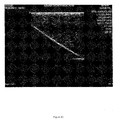
- FIGS. 2A-2D depict four print-outs from the display of a 2D ultrasound monitor (ZonareTM ultrasound system) of a needle in a Blue PhantomTM ultrasound training model tissue block, the needle having particulate material 40 affixed to outer surface 22 of shaft 20 , particulate material 40 including a mixture of a talc particulate material and a calcium carbonate particulate material.
- ZonareTM ultrasound system ZonareTM ultrasound system
- particulate material 40 including a mixture of a talc particulate material and a calcium carbonate particulate material.
- 2E-2H depict four print-outs from the display of a 2D ultrasound monitor (ZonareTM ultrasound system) of a needle in Blue PhantomTM ultrasound training model tissue block, the needle having particulate material dispersed in a polymeric material to provide a hyperechogenic layer in the form of hyperechogenic layer 260 as described hereinbelow, with the polymeric material operating as a matrix or scaffold in which particulate material 40 is embedded.
- Particulate material 40 in the embodiment shown in FIGS. 2E-2H is a talc particulate material having an average median size of 3.8 microns dispersed in PET at a concentration of 15 or 16 weight percent, respectively (as shown in the Figures).
- Particulate material 40 renders the needle visible as it moves from a 90° orientation (e.g., perpendicular) to the direction of the ultrasound waves to an orientation that approaches an alignment with the ultrasound waves.
- the needle image on a 2D ultrasound monitor is thus visible with greater resolution than may be achieved with a needle without hyperechogenic particulate material, both at a 90° angle, and at lesser angles.
- the needle image is visible after the needle has rotated 35° from the perpendicular orientation described.
- FIG. 2H the needle image is visible after the needle has rotated to a steeper angle from the perpendicular orientation. This reflection is different than specular reflectance, since it results from the scattering of the ultrasound waves by the hyperechogenic particulate material 40 .
- wave scattering occurs toward the 2D ultrasound head to make the needle image visible at various angles in the 2D ultrasound plane
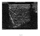
- FIGS. 3A-3E depict five print-outs from the display of the same 2D ultrasound monitor of a bare needle (i.e., without particulate material 40 ) and FIG. 3F depicts a print-out from the display of the same 2D ultrasound monitor of a commercially available needle, which is marketed as an echogenic needle, in the same Blue PhantomTM ultrasound training model tissue block as described above in connection with FIGS. 2A-2D and 2 E- 2 H.
- the bare needle is much less visible than the needle shown in FIGS. 2A-2H
- FIG. 3F that the commercially available echogenic needle is much less visible than the needles shown in FIGS. 2A-2H .
- needle 110 in another embodiment, depicted in FIG. 4 , needle 110 includes rigid shaft 20 and hyperechogenic particulate material 40 , and also includes polymeric coating 50 positioned over at least a portion of shaft 20 .
- particulate material 40 is positioned between shaft 20 and polymeric coating 50 .
- Polymeric coating 50 has a lubricious external surface 52 .
- lubricious when used in connection with a surface means that the surface is sufficiently smooth to allow for a relatively low coefficient of friction between the needle and the tissue it is penetrating, which improves the ease with which needle 110 passes into and through tissue, and decreases the pain and tissue trauma associated with its use.
- Needle 110 optionally can also include a friction lowering material (not shown) affixed to external surface 52 .
- Suitable friction lowering materials that are contemplated for use include, for example, PTFE.
- the friction lowering material is an agent provided as a coating over polymeric coating 50 , over hyperechogenic material 40 or over hyperechogenic layer 260 to reduce the coefficient of friction between the needle and the tissue it is penetrating (i.e., to increase the slipperiness of the needle's surface).
- a friction lowering material that can be used in this manner is silicone. While not being bound by any theory, it is believed that the ultrasound beam passes through the polymeric material and the friction lowering material, if present, and reflects off the hyperechogenic particulate material back to the ultrasound head.
- polymeric coating 50 comprises a biocompatible polymeric material that is stable under conditions encountered during manufacture and use of the needle, and is effective to provide a boundary between hyperechogenic particulate material 40 and the environment of needle 110 .
- polymeric coating 50 comprises polytetrafluoroethylene (PTFE) (trade name TeflonTM).
- PTFE polytetrafluoroethylene
- PET polyethylene terephthalate
- polymeric coating 50 comprises parylene.
- parylene can be formed as a relatively thin layer over particulate material 40 , such as, for example, as thin as 0.1 microns, which can help to minimize the diameter of needle 110 .
- polymeric coating 50 comprises at least one of polyurethane, polyethylene, nylon, polyvinyl chloride, polypropylene, polyester, and silicone.
- polymeric coating 50 is at least partially composed of a polyether ether ketone (PEEK).
- PEEK polyether ether ketone
- the durability of the PEEK allows coating 50 to be formed as a relatively thin layer.
- polymeric coating 50 is desirably non-electrically conductive.
- polymeric coating 50 comprises one or more polymers that impart non-conductivity to coating 50 .
- polymeric coating 50 can be accomplished using a variety of coating techniques, including but not limited to, powder coating; spray coating; extrusion coating; chemical vapor deposition; spin coating; dip coating; injection molding and curing by applying energy, such as, for example, application of light, heat or chemical energy; injection of one-phase or two-phase self-curing materials; growth of an organic layer, and the like.
- coating techniques including but not limited to, powder coating; spray coating; extrusion coating; chemical vapor deposition; spin coating; dip coating; injection molding and curing by applying energy, such as, for example, application of light, heat or chemical energy; injection of one-phase or two-phase self-curing materials; growth of an organic layer, and the like.
- energy such as, for example, application of light, heat or chemical energy
- injection of one-phase or two-phase self-curing materials such as, for example, application of light, heat or chemical energy
- injection of one-phase or two-phase self-curing materials such as, for example, application of light, heat or chemical energy
- powder coating techniques can also be used to apply a coating having a textured surface, such as, for example, a surface having a texture commonly referred to as an “orange peel” texture due to the resemblance of the texture to the bumpy surface of the skin of an orange or other citrus fruit.
- an orange peel texture, or other surface texture is included as a feature of the coating in certain embodiments of the present application.
- needle 210 includes rigid shaft 20 , hyperechogenic particulate material 40 and a polymeric material 250 , which can be composed of a thermoplastic polymer resin, such as, for example, the polymers as described above in connection with polymeric coating 50 .
- particulate material 40 is dispersed in polymeric material 250 to provide hyperechogenic layer 260 in which polymeric material 250 operates as a matrix or scaffold in which particulate material 40 is embedded.
- hyperechogenic particulate material 40 has a density that is different from that of polymeric material 250 . While the embodiment depicted in FIG.
- hyperechogenic layer 260 extending in the distal direction only to a point that is proximal of the bevel tip, this is not intended to be a limiting feature of the application, it being understood that in alternate embodiments hyperechogenic layer extends distally to a different point. Indeed, in one preferred embodiment, hyperechogenic layer 260 covers the entire needle shaft, including the tip.
- Hyperechogenic layer 260 has a lubricious external surface 262 to allow for a relatively low coefficient of friction between needle 210 and the tissue it is penetrating, which improves the ease with which needle 210 passes into and through tissue, and decreases the pain and tissue trauma associated with its use.
- Needle 210 optionally can also include a friction lowering material (not shown) affixed to external surface 262 , which friction lowering material can be, for example, an agent such as silicone provided as a coating over polymeric coating 50 or an agent that is mixed into polymeric coating 50 . While not being bound by any theory, it is believed that the ultrasound beam passes through the polymeric material and the friction lowering material, if present, and reflects off the hyperechogenic particulate material back to the ultrasound head.
- Particulate material 40 may be interspersed throughout hyperechogenic layer 260 in a uniform pattern or non-uniform manner. For example, it may be more cost-effective if the particles composing the particulate material 40 vary considerably in size, as opposed to maintaining a narrow size range for the particles. Particulate material 40 can be simply mixed into the starting materials used to form polymeric material 250 such that particulate material 40 is randomly dispersed throughout polymeric material 250 in hyperechogenic layer 260 when it is applied to shaft 20 . In one manner of applying hyperechogenic layer 260 to shaft 20 , particulate material 40 and a suitable polymeric material 250 , preferably a thermoplastic polymer material, are simultaneously applied to the surface of shaft 20 using a powder coating technique.
- a suitable polymeric material 250 preferably a thermoplastic polymer material
- the powder coating method includes providing a fine powder mixture that includes the hyperechogenic particulate material and the polymeric material, application of the mixture to the shaft of a properly prepared needle, and heating the mixture to melt the polymeric mixture and form a uniform film with the particulate material entrained therein.
- the fine powder mixture used in the powder coating application can be provided by mixing a selected particulate material 40 into a selected starting polymeric material, such as, for example, beads or pellets of the selected starting polymeric material, which mixture is then baked and processed into a powder form.
- a selected starting polymeric material such as, for example, beads or pellets of the selected starting polymeric material
- the powder form can be made by placing a mixture of the selected particulate material and the selected starting polymeric material into an extruder where it is heated and extruded, followed by rolling the extruded mixture in a flat sheet that is then cooled and broken into small chips. The chips can then be milled and sieved to make a fine powder.
- a hyperechogenic particulate material in a fine powder form can simply be mixed with a polymeric material in fine powder form.
- the powder form of the mixture (whether provided by the extrusion and milling approach or by a simple mixing approach) can be applied to shaft 20 using a powder coating method, examples of which are well known to a person of ordinary skill in the art, thereby forming hyperechogenic layer 260 .
- the powder coating can be applied to the surface of the shaft by spraying the powder using an electrostatic gun, which imparts a positive electric charge on the powder.
- hyperechogenic layer 260 includes polyethylene terephthalate and a particulate talc material that has a median average particle size of about 9 microns, such as, for example, EliteTalcTM 3000 USP talc, which is commercially available from Cimbar Performance Minerals (Cartersville, Ga.), in which the talc is present at a concentration of about 10 to about 25 weight percent.
- the PET/talc mixture is preferably applied to the surface of the needle in this embodiment using a powder coating technique.
- Such a hyperechogenic layer is particularly well suited for a use on a 21 or 22 gauge needle.
- hyperechogenic layer 260 includes polyethylene terephthalate and a particulate talc material that has a median average particle size of about 3.8 microns, such as, for example, EliteTalcTM 4000 USP talc, which is commercially available from Cimbar Performance Minerals (Cartersville, Ga.), in which the talc is present at a concentration of about 10 to about 25 weight percent. In one implementation of this embodiment, the talc is present at a concentration of about 10 to about 20 weight percent, more preferably about 15 weight percent, and the PET/talc mixture is preferably applied to the surface of the needle using a powder coating technique.
- a particulate talc material that has a median average particle size of about 3.8 microns, such as, for example, EliteTalcTM 4000 USP talc, which is commercially available from Cimbar Performance Minerals (Cartersville, Ga.), in which the talc is present at a concentration of about 10 to about 25 weight percent. In one implementation of this embodiment, the
- the hyperechogenic particulate material be of a type that is electrically non-conductive, or substantially non-conductive so that particulate material 40 does not significantly impair the electrically insulative properties of polymeric material 250 in layer 260 .
- a particulate talc material has been found to be substantially nonconductive, allowing it to be a suitable particulate material in this embodiment.
- a needle that includes a hyperechogenic particulate material as described in connection with the various embodiments herein may be in a wide variety of shapes and sizes.
- representative needles may be constructed to have a wide variety of forms and to operate in a wide variety of ways, including but not limited to the commonly-known forms useful as biopsy needles, ablation probes, needles used to implant treatment therapies, such as, for example, implant devices, radioactive seed implants or drugs, and needles used in blocking peripheral nerves.
- the disclosures provided herein are contemplated to be suitable for other types of devices or components that can be suitably modified to include hyperechogenic particulate materials.
- medical devices for which real-time imaging would be useful include stents, stylets, and the like, or softer, more flexible devices or components thereof, such as, for example, flexible catheters and the like.
- Other components that can be suitably modified as described herein include supporting bands or outer sheaths for use in connection with such medical devices.
- a therapeutic agent such as, for example, a drug or bioactive agent, is included with the hyperechogenic particulate material and/or in the polymeric coating 50 or polymeric material 250 to impart biological properties to the surface of the needle or other medical device.
- the therapeutic agent can be included in the friction lowering material. Whether present in a hyperechogenic particulate material, a polymeric coating, a hyperechogenic layer or a friction lowering material, the therapeutic agent can be released over time as the needle is positioned in contact with tissue or fluid.
- bioactive agent includes, but is not limited to, proteins, enzymes, enzyme inhibitors, immunological molecules, hormones, neurotransmitters, peptides, lipids, nucleic acids, sugars, carbohydrates, glycoproteins, lectins, bacteria, viruses, replication inhibitors, proteases, antibiotics, antifungals, bacteriostatic compounds, toxins, microbials, anti-microbials, growth factors, angiogenic factors, nutrients, and vitamins.
- Suitable drugs or bio-active agents include, for example, without limitation, thrombo-resistant agents, antibiotic agents, anti-tumor agents, anti-viral agents, anti-angiogenic agents, angiogenic agents, anti-inflammatory agents, cell cycle regulating agents, their homologs, derivatives, fragments, pharmaceutical salts and combinations thereof.
- Useful thrombo-resistant agents can include, for example, heparin, heparin sulfate, hirudin, chondroitin sulfate, dermatan sulfate, keratin sulfate, lytic agents, including urokinase and streptokinase, their homologs, analogs, fragments, derivatives and pharmaceutical salts thereof.
- Useful antibiotics can include, for example, penicillins, cephalosporins, vancomycins, aminoglycosides, quinolones, polymyxins, erythromycins, tetracyclines, chloramphenicols, clindamycins, lincomycins, sulfonamides, their homologs, analogs, fragments, derivatives, pharmaceutical salts and mixtures thereof.
- Useful anti-tumor agents can include, for example, paclitaxel, docetaxel, alkylating agents including mechlorethamine, chlorambucil, cyclophosphamide, melphalan and ifosfamide; antimetabolites including methotrexate, 6-mercaptopurine, 5-fluorouracil and cytarabine; plant alkaloids including vinblastine, vincristine and etoposide; antibiotics including doxorubicin, daunomycin, bleomycin, and mitomycin; nitrosureas including carmustine and lomustine; inorganic ions including cisplatin; biological response modifiers including interferon; enzymes including asparaginase; and hormones including tamoxifen and flutamide; their homologs, analogs, fragments, derivatives, pharmaceutical salts and mixtures thereof.
- alkylating agents including mechlorethamine, chlorambucil, cyclophosphamide, mel
- Useful anti-viral agents can include, for example, amantadines, rimantadines, ribavirins, idoxuridines, vidarabines, trifluridines, acyclovirs, ganciclovirs, zidovudines, foscarnets, interferons, their homologs, analogs, fragments, derivatives, pharmaceutical salts and mixtures thereof.
- a needle having a hyperechogenic particulate material affixed thereto as described herein is a needle used for peripheral nerve blockage in a regional anesthesia application that is configured to create electrical current at its tip for nerve stimulation. It is a well known medical practice to produce regional anesthesia in a patient by depositing a local anesthetic along the path of one or more peripheral nerves. The success of the technique is largely dependent upon the ability of the clinician to deposit a local anesthetic in close proximity to the nerve without causing trauma to the nerve as may result from contacting the needle directly with the nerve.
- Local anesthetics comprise a class of drugs which reversibly interact with a nerve in a manner such that the propagation of signals along the nerve fiber is significantly reduced, or stopped altogether.
- drugs When such drugs are deposited along large nerve trunks, such as the femoral nerve in the groin or the nerve trunk of the brachial plexus in the axilla or neck, the effect is to make the targeted body structure, such as a body limb, insensate or “numb.” This phenomena is similar to that experienced by a patient at a dentist's office when local anesthetics are used for placement of tooth fillings.
- the relevant nerve or nerves When the local anesthetic is intended to be injected into the groin, neck or axilla, the relevant nerve or nerves must, of course, be located before the injection is given.
- a general understanding of surface anatomy allows the general area of the nerve to initially be located. Historically the nerve was located by eliciting a paraesthesia, or pain, resulting from the needle coming into contact with the nerve fiber. This is very similar to the sensation experienced by hitting the “crazy bone,” where the ulnar nerve is stimulated by pressure being placed on it between the skin and the bone.
- this process is done with a needle, however, the risk of damaging a nerve fiber is high, with the possible result of permanent nerve injury. This technique has been largely abandoned due to the high possibility of such permanent injury.
- Nerve block systems are provided with certain features to minimize damage to the nerve.
- a first feature is to cut the needle end with a “B” bevel, at an angle of roughly 45°. This action produces a lowered incidence of impinging nerve fibers when the needle is directed at a nerve trunk. This needle angle tends to allow nerve fibers to roll out of the way, as opposed to more common sharp tips seen in needles of the type that are used to puncture skin for the introduction of, e.g., solutions or catheters below the skin.
- a second feature is to provide the needle with a coaxial design, consisting of a needle shaft covered with a plastic coating, such as, for example, PEEK or PTFE.
- the needle shaft is connected to an electrode, and the needle electrode system and a grounding electrode (also referred to as a “skin electrode”) are connected to a commercially available nerve stimulation box.
- An electrical circuit is formed when the needle is placed in the patient's tissue and the grounding electrode is connected to the patient's skin, for example, with a conventional EKG electrode.
- This circuit is capable of delivering adjustable pulses of electrical energy through the needle, through the patient's tissues, and to the skin electrode.
- the motor nerve fibers are stimulated to cause muscles innervated by the nerve to twitch by electrical stimulation resulting from the electrical current flow in the electrical circuit.
- the clinicians are, in effect, attempting to localize the nerve without actually contacting the nerve fibers in a manner that might cause permanent damage to the nerve.
- Needle insertion by the aforementioned technique is based upon clinical judgment, and therefore, is not precise.
- the amount of electric current necessary to make the correct muscle twitch for the nerve to be blocked is determined by the proximity of the needle to the nerve. Generally, only a small amount of current is required, since resistance is typically minimal as the needle approaches the nerve. In clinical practice, this is typically performed at 1 to 2 Hz stimulation frequency, with an optimal current of 1.0 milliamps or less to bring the needle in close enough proximity to the nerve for drug injection.
- the actual voltage required is a property of the particular peripheral nerve stimulator utilized in the technique. It is set at a value to produce a motor response without pain.
- Nerve block needle embodiments are described herein that include a hyperechogenic particulate material to enhance the ultrasound imaging characteristics of a nerve block needle.
- nerve block needle 310 includes inner shaft 20 , which is made of a conductive material, for example, a conductive metal or metal alloy, such as surgical grade steel.
- Polymeric coating 50 covers most of the length of the shaft, and extends generally from the proximal end 23 of the needle nearly to the bare metal needle tip portion 25 of the distal end 24 of the needle, leaving only the tip portion 25 uncovered.
- hyperechogenic particulate material 40 Positioned between shaft 20 and polymeric coating 50 is hyperechogenic particulate material 40 , which can be affixed to shaft as described above.
- polymeric coating 50 and the layer of hyperechogenic particulate material 40 positioned between shaft 20 and polymeric coating 50 are replaced by a hyperechogenic layer having a particulate material 40 dispersed in a polymeric material, as described hereinabove with respect to hyperechogenic layer 260 .
- the hyperechogenic layer can be applied using a powder coating technique, and can cover the entire tip portion of shaft 20 .
- Hyperechogenic particulate material 40 enhances the reflection of ultrasound waves toward an emitter receiver array of a 2D ultrasound machine (not shown), thereby allowing enhanced needle visualization with a 2D ultrasound machine.
- needle 310 is inserted into the patient's tissue and advanced toward a peripheral nerve with greater precision than may be achieved with either ultrasound or peripheral nerve stimulation alone.
- conductive hub 360 is affixed to shaft 20 of needle 310 , which is in direct contact with shaft 20 to allow for electrical current to pass from hub 360 to shaft 25 .
- Wire 365 is affixed at its distal end to hub 360 , also in direct contact to allow for electrical current to pass from wire 365 to hub 360 .
- the proximal end of wire 365 is connected to a source of electrical current (such as, for example, electrical stimulation device 391 as shown in FIG. 7 ).
- the proximal end of wire 365 may terminate at a mechanical connector (not shown) of a type that is suitable for connection to an outlet of the peripheral nerve stimulator 391 or other source of electrical current.
- needle tip portion 25 of the hyperechogenic stimulating block needle 310 is bevel cut at an angle of approximately 45°, or in other words, at a less acute angle than a standard needle.
- Encasing hub 360 is insulating enclosure 370 , which can be composed of a plastic or other electrically insulating material.
- conduit 380 Also affixed to proximal end 23 of shaft 20 in fluid communication with lumen 30 of shaft 20 is conduit 380 , which can be used to deliver a local anesthetic drug to lumen 30 of shaft 20 for injection of the drug through lumen 30 when deemed appropriate by a medical care provider using needle 310 .
- Conduit 380 is sized and shaped for attachment to a syringe, tube, or other drug delivery device in well known fashion.
- Needle 310 can be utilized to deposit drugs near a nerve, e.g., to produce local or regional anesthesia at a targeted area in the body of the patient.
- needle 310 may be utilized in a process for blocking a peripheral nerve that combines nerve stimulation and 2D ultrasound visualization techniques.
- Polymeric coating 50 is composed of a polymer material that is substantially electrically non-conducting. Leaving tip portion 25 bare allows for an electrical current to be passed to tip portion 25 of the needle and through the surrounding tissue to grounding electrode 390 (also referred to as “skin electrode”), as depicted in FIG. 7 .
- grounding electrode 390 also referred to as “skin electrode”
- This type of needle construction ensures maximal current density, as the current can only exit at the uncovered metal needle tip.
- the needle is connected at its proximal end to wire 365 (also referred to as “needle electrode 365 ”). Needle electrode 365 and a grounding electrode 390 are then connected to battery powered electrical stimulation device 391 (also referred to as “peripheral nerve stimulator 391 ”).
- battery powered electrical stimulation device 391 also referred to as “peripheral nerve stimulator 391 ”.
- peripheral nerve stimulator 391 has two controls, namely a frequency control knob 392 , and an amperage or current control knob 393 . Also, in the example shown, peripheral nerve stimulator 391 is provided with an optional digital readout 394 for displaying the current when a circuit is formed.
- Polymeric coating 50 insulates shaft 20 from the remaining patient tissue, ensuring that electrical current primarily exits at the needle tip portion 25 .
- an electrical circuit is formed between the needle tip portion 25 and grounding electrode 390 .
- Electrical stimulation device 391 can be adjusted from 5.0 mA down to approximately 0.3 mA. The closer needle tip portion 25 is to the nerve, the less current is needed to depolarize the nerve. This allows the practitioner to adjust needle placement with electrical stimulation for optimal positioning relative to the target nerve while minimizing the risk of nerve damage.
- the practitioner will then deposit a local anesthetic solution through the needle and into the area surrounding the nerve. The local anesthetic solution will block nerve impulses traveling to and from the brain to the area the nerve innervates, thereby achieving the desired local numbing.
- the target tissue position is a position near a peripheral nerve to be blocked, and as the needle is advanced toward the target peripheral nerve, not only does the clinician view the real-time position of the needle relative to the nerve using a 2D ultrasound apparatus, but the clinician also controls peripheral nerve stimulator 391 to emit DC current through the distal portion of the needle at a predetermined voltage that is determined according to the characteristics of the peripheral nerve stimulator.
- a pathway is thereby formed for electrons to flow from peripheral nerve stimulator 391 through needle electrode 365 to the nerve block needle 310 , and through the shaft 20 (which is electrically insulated from the patient) and the tip portion 25 of needle 310 .
- the electrons pass through the patient's tissue and exit the patient's tissue through skin electrode 390 , returning to peripheral nerve stimulator 391 via grounding electrode 390 .
- the target peripheral nerve is located by activating the peripheral nerve stimulator 391 to form the circuit.
- Stimulator frequency knob 392 is adjusted to emit an electrical pulse, most commonly with a range of 1 to 2 Hz.
- Stimulator amperage control knob 393 is adjusted to elicit a motor response when the needle is advanced in the region of the target peripheral nerve. The amperage is commonly set at about 1.0-2.0 milliamps to search for the general nerve location.
- the nerve block needle 310 is advanced toward the target peripheral nerve using general knowledge of surface anatomy, and with the guidance of the 2D ultrasound apparatus 395 .
- the motor response is elicited by stimulation of the motor nerve fibers by current flowing through the nerve.
- the correct nerve to be blocked can be determined by a general understanding of the anatomy of the nervous system, and in particular, by recognizing which nerve will cause a specific part of the body to move as a result of the electrical stimulation.
- the motor response is different for each nerve to be blocked. As the needle is advanced toward the target nerve, the motor response becomes more intense, since less tissue is present between the needle tip portion 25 and target peripheral nerve, thereby reducing the resistance to current flow.
- the current is decreased as the needle approaches the nerve, as less current is required to elicit a motor response.
- a current of 1.0 milliamps or less elicits a motor response
- FIG. 7 illustrates a system for peripheral nerve block that can be used in this method.
- the system includes a hyperechogenic stimulating block needle 310 , a 2D ultrasound apparatus 395 , and a peripheral nerve stimulator 391 .
- needle 310 is advanced toward the target location using general knowledge of surface anatomy, and with the guidance of 2D ultrasound apparatus 395 , which includes monitor 396 , computer 397 , head cord 398 and ultrasonic head 399 .
- Ultrasonic head 399 typically includes a series of piezoelectric effect crystals in alignment. Ultrasound head 399 is capable of sending out a series of ultrasound beams, and to receive reflected energy.
- the reflected energy is amplified, processed, and integrated in 2D ultrasound apparatus 395 , thereby rendering a 2D planar image of the tissue below the head, which is displayed on monitor 396 .
- the target soft tissue location is rendered visible relative to surrounding structures in a lateral and axial fashion in the plane of the 2D ultrasound apparatus 395 .
- the signal from ultrasound machine head 399 is received by computer 397 via 2D ultrasound head cord 398 .
- the ability to see the needle path and the target peripheral nerve to be blocked, in combination with peripheral nerve stimulation, allows the target peripheral nerve to be approached with more precision than has previously been possible.
- the position of the needle can be resolved anatomically using 2D ultrasound by simultaneous visibility of the needle path and the target peripheral nerve, and can be resolved physiologically by using peripheral nerve stimulation to elicit a motor response by minimizing the current.
- This allows the needle tip portion 25 to be directed to a closer proximity to the peripheral nerve when compared to the use of peripheral nerve stimulation alone, or the use of 2D ultrasound and peripheral nerve stimulation using a needle without hyperechogenic particulate material.
- drugs can be deposited more easily and precisely than has previously been possible.
- a nerve block needle having a general configuration as set forth in FIGS. 6 and 7 can alternatively have a form corresponding to the embodiment depicted in FIG. 5 , in which hyperechogenic particulate material 40 is embedded in a polymeric material 250 to form a hyperechogenic layer 260 .
- hyperechogenic layer 260 covers the length of the shaft.
- the tip is left uncovered.
- the tip is covered with the hyperechogenic layer 260 .
- hyperechogenic layer 260 is electrically insulative. It is within the skill of a person skilled in the art to select a suitable polymeric material and a suitable hyperechogenic particulate material to achieve adequate electrical insulative properties for this embodiment. It is desirable in these embodiments that polymeric coating 50 and polymeric material 250 be composed of a highly durable and electrically insulative material, such as, for example, PEEK, PTFE, PET or parylene.
- one aspect of the present invention includes a method of guided placement of a needle tip using an ultrasonic imaging apparatus.
- This method includes providing a needle that includes a rigid shaft having a longitudinal axis, a proximal end, a distal end, and an outer surface extending from the proximal end to the distal end, the distal end including a tip portion defining a point, and a hyperechogenic particulate material affixed to the shaft along at least a portion of the outer surface, the hyperechogenic particulate material being operable in response to a beam of ultrasound waves in a two-dimensional ultrasound plane to produce an image of the needle, even when the needle is in a position forming a non-90° angle between the longitudinal axis and the direction of the ultrasound waves in the two-dimensional ultrasound plane, thereby enhancing the ultrasonic imaging characteristics of the needle; inserting the needle into soft tissue of a patient; visualizing the needle with a two-dimensional ultrasound imaging apparatus;
- the present specification contemplates methods for ultrasonically imaging a wide variety of hyperechogenic needles not limited to nerve block needles, and methods for ultrasonically imaging a hyperechogenic medical device other than a needle in biological tissue.
- the method includes providing a device having a hyperechogenic particulate material affixed to an outer surface of the device; and inserting the hyperechogenic medical device into the tissue of a patient under two-dimensional ultrasound imaging. More particularly, the method includes directing an ultrasonic beam toward the hyperechogenic device during the inserting and receiving an ultrasound image produced by the particulate material in response to the ultrasonic beam.
- the method includes providing a rigid shaft formed of a material such as stainless steel or plastic, the shaft having an inner surface defining a lumen therethrough, an outer surface, a proximal end and a distal end defining a distal tip portion that includes a sharp tissue-penetrating point; and affixing a hyperechogenic particulate material onto at least a portion of the outer surface of the shaft.
- the particulate material can be affixed to the shaft, for example, using an adhesive or resin as described above.
- a polymeric coating is applied over the particulate material to provide a barrier between the particulate material and the needle's environment.
- the polymeric coating can be applied in a wide variety of ways as would occur to a person skilled in the art, and as described above.
- the needle In making a hyperechogenic needle in which the hyperechogenic particulate material is embedded in a polymeric material, the needle can be made by providing a rigid shaft as described above; positioning the shaft in an extruder or injection mold; providing a mixture of plastic pellets and hyperechogenic particulate material; and feeding the mixture to the extruder or injection mold effective to melt the plastic pellets, mix the particulate material into the molten plastic, and apply the molten mixture to the shaft for hardening to provide a hyperechogenic needle.
- Mixing of the plastic pellets and the particulate material can be achieved, for example, using a mixer operable to gravity feed the parts to be mixed into a screw or worm-gear type mechanism well known in extruder machines and other plastic manufacturing equipment.
- the mixture Before, during or after the mixing, the mixture may be heated to maintain the mixture in a molten or liquid state allowing it to be formed to the desired shape.
- the mixture of hyperechogenic particulate material and polymeric material can be applied to the surface of a needle using a powder coating process, examples of which are well known and understood by a person of ordinary skill in the art.
- plastic processing techniques are described above, it is not intended that the present application be limited to these techniques, it being understood that a wide variety of other techniques are known and can be employed for applying a plastic coating to a device as described herein, or to apply a hyperechogenic layer that includes a particulate material dispersed in a polymeric material.
- Non-limiting examples of such other techniques include spray coating; chemical vapor deposition; spin coating; dip coating; and curing by applying energy, such as, for example, application of light, heat or chemical energy to a precursor material positioned on the needle shaft; self-curing of one-phase or two-phase materials, and the like.
- a rigid shaft comprising surgical grade steel is coated with a hyperechogenic particulate material comprising talc and calcium carbonate using a resin.
- the coating comprises from 0 to about 70 weight percent talc, from 0 to about 70 weight percent calcium carbonate and from about 30 to about 60 weight percent resin.
- the coating comprises from 30 to about 60 weight percent talc, from 1 to about 25 weight percent calcium carbonate and from about 30 to about 60 weight percent resin.
- the coating comprises from 35 to about 50 weight percent talc, from 5 to about 15 weight percent calcium carbonate and from about 30 to about 60 weight percent resin.
- the coating comprises from about 5 to about 70% talc and from about 30 to about 95% resin.
- any of the coating compositions described herein may also include, but does not necessarily include, a resin solvent.
- a polymeric coating such as, for example, a parylene coating or a PET coating.
- the particulate material is dispersed in the polymeric coating, such as, for example, a PET coating.
- polymeric coating or “polymeric material” are used to denote any suitable biocompatible polymer.
- Exemplary polymeric materials include, but are not limited to, thermoplastic polymers, thermoset polymers, elastomers, adhesives, resins, sealants, and composites thereof.
- rigid shaft is intended to encompass a variety of materials that are suitable for a given medical use, and include a wide range of materials such as polymeric materials, metals and ceramics. However, in an embodiment in which the rigid shaft is electrically conductive, it will be appreciate that the shaft will typically be made of a metal.
- Exemplary metals that can be employed include medical grade stainless steel, titanium or titanium alloy.
- the expression “soft tissue” is used herein to refer to any host tissue other than bone.
- the particulate material used may meet all of the United States Pharmacopoeia requirements for chemical and biological purity.
- the particulate material may also conform to the requirements of the Cosmetic Manufacturer's Association for maximum limits on arsenic, lead, and heavy metals.
- particulate material 40 comprises a particulate talc material and/or a particulate calcium carbonate material and the like
- embodiments with these materials are exemplary, and it is not intended that the present application be limited thereto, it being understood that a variety of other materials can be used that have similar ultrasound imaging properties as described herein.
- particulate material 40 comprises particulate wollastonite material.
- the hyperechogenic particulate material can have a variety of sizes and shapes.
- the hyperechogenic particulate material has an average median size of from about 1 to about 18 microns.
- a needle effective for guided positioning in soft tissue of a patient with the aid of a real-time two-dimensional ultrasonic imaging apparatus comprising:
- a rigid shaft having a longitudinal axis, a proximal end, a distal end, and an outer surface extending from the proximal end to the distal end, said distal end including a tip portion defining a point;
- a hyperechogenic layer affixed to said shaft along at least a portion of the outer surface
- said hyperechogenic layer comprises a polymeric material having a hyperechogenic particulate material dispersed therein;
- said hyperechogenic particulate material is operable in response to a beam of ultrasound waves in a two-dimensional ultrasound plane to produce an image of said needle when said needle is in a position forming a non-90° angle between the longitudinal axis and the direction of the ultrasound waves in the two-dimensional ultrasound plane, thereby enhancing the ultrasonic imaging characteristics of the needle;
- said hyperechogenic particulate material comprises a particulate talc material.
- hyperechogenic particulate material further comprises a member selected from the group consisting of a particulate calcium-containing material, a silicate, a mineral including calcium, barium, aluminum or magnesium, graphite, silica and a carbonate, sulfate, oxide, hydroxide or phosphate of calcium, magnesium, barium or aluminum.
- polymeric material comprises a member selected from the group consisting of polyurethane, polyethylene, nylon, polytetrafluoroethylene, polyvinyl chloride, polypropylene, polyester, parylene, silicone and polyethylene terephthalate
- a rigid shaft having a longitudinal axis, a proximal end, a distal end, and an outer surface extending from the proximal end to the distal end, said distal end including a tip portion defining a point;
- a hyperechogenic particulate material affixed to said shaft along at least a portion of the outer surface, said hyperechogenic particulate material operable in response to a beam of ultrasound waves in a two-dimensional ultrasound plane to produce an image of said needle when said needle is in a position forming a non-90° angle between the longitudinal axis and the direction of the ultrasound waves in the two-dimensional ultrasound plane, thereby enhancing the ultrasonic imaging characteristics of the needle;
- a polymeric coating positioned over at least a portion of said shaft and covering said hyperechogenic particulate material, the polymeric coating having a lubricious external surface;
- said hyperechogenic particulate material comprises a particulate talc material.
- a needle effective for guided positioning in soft tissue of a patient with the aid of a real-time two-dimensional ultrasonic imaging apparatus comprising:
- a rigid shaft having a longitudinal axis, a proximal end, a distal end, and an outer surface extending from the proximal end to the distal end, said distal end including a tip portion defining a point;
- a hyperechogenic particulate material affixed to said shaft along at least a portion of the outer surface, said hyperechogenic particulate material operable in response to a beam of ultrasound waves in a two-dimensional ultrasound plane to produce an image of said needle when said needle is in a position forming a non-90° angle between the longitudinal axis and the direction of the ultrasound waves in the two-dimensional ultrasound plane, thereby enhancing the ultrasonic imaging characteristics of the needle;
- a polymeric coating positioned over at least a portion of said shaft and covering said hyperechogenic particulate material, the polymeric coating having a lubricious external surface;
- said hyperechogenic particulate material comprises a member selected from the group consisting of a particulate talc material, a particulate calcium-containing material, a silicate, a mineral including calcium, barium, aluminum or magnesium and a carbonate, sulfate, oxide, hydroxide or phosphate of calcium, magnesium, barium or aluminum.
- hyperechogenic particulate material comprises a mineral including calcium, barium, aluminum or magnesium.
- silicate comprises a member selected from the group consisting of a wollastonite, a talc, a quartz, a phyllosilicate, a montmorillonite, an inosilicate and a tectosilicate.
- hyperechogenic particulate material comprises a carbonate, sulfate, oxide, hydroxide or phosphate of calcium, magnesium, barium or aluminum.
- polymeric coating comprises a member selected from the group consisting of polyurethane, polyethylene, nylon, polytetrafluoroethylene, polyvinyl chloride, polypropylene, polyester, parylene and silicone.
- a needle effective for guided positioning in soft tissue of a patient with the aid of a real-time two-dimensional ultrasonic imaging apparatus comprising:
- a rigid shaft having a longitudinal axis, a proximal end, a distal end, and an outer surface extending from the proximal end to the distal end, said distal end including a tip portion defining a point;
- a hyperechogenic particulate material affixed to said shaft along at least a portion of the outer surface, said hyperechogenic particulate material operable in response to a beam of ultrasound waves in a two-dimensional ultrasound plane to produce an image of said needle when said needle is in a position forming a non-90° angle between the longitudinal axis and the direction of the ultrasound waves in the two-dimensional ultrasound plane, thereby enhancing the ultrasonic imaging characteristics of the needle;
- a polymeric coating positioned over at least a portion of said shaft and covering said hyperechogenic particulate material, the polymeric coating having a smooth external surface;
- said hyperechogenic particulate material has a median average particle size of from about 1 to about 18 microns.
- a needle effective for guided positioning in soft tissue of a patient with the aid of a real-time two-dimensional ultrasonic imaging apparatus comprising:
- a rigid shaft having a longitudinal axis, a proximal end, a distal end, and an outer surface extending from the proximal end to the distal end, said distal end including a tip portion defining a point;
- a hyperechogenic particulate material affixed to said shaft along at least a portion of the outer surface, said hyperechogenic particulate material operable in response to a beam of ultrasound waves in a two-dimensional ultrasound plane to produce an image of said needle when said needle is in a position forming a non-90° angle between the longitudinal axis and the direction of the ultrasound waves in the two-dimensional ultrasound plane, thereby enhancing the ultrasonic imaging characteristics of the needle;
- a polymeric coating positioned over at least a portion of said shaft and covering said hyperechogenic particulate material, the polymeric coating having a lubricious external surface;
- said hyperechogenic particulate material comprises a member selected from the group consisting of graphite and silica.
- a system for guided placement of the tip of a needle comprising:
- a needle configured for insertion into soft tissue of a patient, said needle comprising
- a two-dimensional ultrasound apparatus capable of visualizing at least a portion of the needle in a segment of tissue of the patient.
- the needle is configured for use in blocking a nerve of a patient; wherein said needle shaft is electrically conductive; wherein said polymeric coating is generally non-conductive; wherein said hyperechogenic particulate material extends along at least a portion of a length of said shaft; and wherein the system further comprises a peripheral nerve stimulator capable of electrical connection with the shaft for transmitting an electrical pulse therethrough.
- peripheral nerve stimulator is capable of providing an adjustable current for eliciting a motor response.
- a method for positioning a needle in soft tissue of a patient with the aid of a real-time two-dimensional ultrasonic imaging apparatus comprising:
- a needle that includes a rigid shaft having a longitudinal axis, a proximal end, a distal end, and an outer surface extending from the proximal end to the distal end, said distal end including a tip portion defining a point, and a hyperechogenic particulate material affixed to the shaft along at least a portion of the outer surface, the hyperechogenic particulate material being operable in response to a beam of ultrasound waves in a two-dimensional ultrasound plane to produce an image of said needle when said needle is in a position forming a non-90° angle between the longitudinal axis and the direction of the ultrasound waves in the two-dimensional ultrasound plane, thereby enhancing the ultrasonic imaging characteristics of the needle;
- said hyperechogenic particulate material comprises a member selected from the group consisting of a particulate talc material, a particulate calcium-containing material, a silicate, a mineral including calcium, barium, aluminum or magnesium and a carbonate, sulfate, oxide, hydroxide or phosphate of calcium, magnesium, barium or aluminum.
- a method for blocking a nerve of a patient comprising:
- a hyperechogenic stimulating block needle said needle comprising an electrically conductive rigid shaft having a longitudinal axis, a proximal end, a distal end, and an outer surface extending from the proximal end to the distal end, said distal end including a tip portion defining a point; a hyperechogenic particulate material affixed to said shaft along at least a portion of the outer surface, said hyperechogenic particulate material operable in response to a beam of ultrasound waves in a two-dimensional ultrasound plane to produce an image of said needle when said needle is in a position forming a non-90° angle between the longitudinal axis and the direction of the ultrasound waves in the two-dimensional ultrasound plane, thereby enhancing the ultrasonic imaging characteristics of the needle; and a polymeric coating positioned over at least a portion of said shaft and covering said hyperechogenic particulate material, the polymeric coating having a lubricious external surface; wherein said hyperechogenic particulate material comprises a member selected from the group consisting of a
- said electrical nerve stimulation comprises emitting an electrical pulse in a vicinity of said nerve, and adjusting an amount of current to elicit a motor response when said needle tip is advanced toward said nerve.
- a method for making a needle for guided positioning in soft tissue of a patient with the aid of a real-time two-dimensional ultrasonic imaging apparatus comprising:
- a rigid shaft having a longitudinal axis and an outer surface
- a hyperechogenic particulate material comprising a member selected from the group consisting of a particulate talc material, a particulate calcium-containing material, a silicate, a mineral including calcium, barium, aluminum or magnesium and a carbonate, sulfate, oxide, hydroxide or phosphate of calcium, magnesium, barium or aluminum; and
Abstract
Description
-
- a rigid shaft having a longitudinal axis, a proximal end, a distal end, and an outer surface extending from the proximal end to the distal end, said distal end including a tip portion defining a point;
- a hyperechogenic particulate material affixed to said shaft along at least a portion of the outer surface, said hyperechogenic particulate material operable in response to a beam of ultrasound waves in a two-dimensional ultrasound plane to produce an image of said needle when said needle is in a position forming a non-90° angle between the longitudinal axis and the direction of the ultrasound waves in the two-dimensional ultrasound plane, thereby enhancing the ultrasonic imaging characteristics of the needle; and
- a polymeric coating positioned over at least a portion of said shaft and covering said hyperechogenic particulate material, the polymeric coating having a lubricious external surface;
- wherein said hyperechogenic particulate material comprises a member selected from the group consisting of a particulate talc material, a particulate calcium-containing material, a silicate, a mineral including calcium, barium, aluminum or magnesium and a carbonate, sulfate, oxide, hydroxide or phosphate of calcium, magnesium, barium or aluminum; and
Claims (27)
Priority Applications (1)
| Application Number | Priority Date | Filing Date | Title |
|---|---|---|---|
| US13/166,383 US8628475B2 (en) | 2010-06-24 | 2011-06-22 | Hyperechogenic needles |
Applications Claiming Priority (2)
| Application Number | Priority Date | Filing Date | Title |
|---|---|---|---|
| US39837910P | 2010-06-24 | 2010-06-24 | |
| US13/166,383 US8628475B2 (en) | 2010-06-24 | 2011-06-22 | Hyperechogenic needles |
Publications (2)
| Publication Number | Publication Date |
|---|---|
| US20110319758A1 US20110319758A1 (en) | 2011-12-29 |
| US8628475B2 true US8628475B2 (en) | 2014-01-14 |
Family
ID=44509894
Family Applications (1)
| Application Number | Title | Priority Date | Filing Date |
|---|---|---|---|
| US13/166,383 Expired - Fee Related US8628475B2 (en) | 2010-06-24 | 2011-06-22 | Hyperechogenic needles |
Country Status (2)
| Country | Link |
|---|---|
| US (1) | US8628475B2 (en) |
| WO (1) | WO2011163368A1 (en) |
Cited By (7)
| Publication number | Priority date | Publication date | Assignee | Title |
|---|---|---|---|---|
| US20110313391A1 (en) * | 2009-01-27 | 2011-12-22 | Knapp Ii Keith N | Infusion set with anesthetic compound |
| US20120283775A1 (en) * | 2011-05-06 | 2012-11-08 | Edward H Cully | Echogenic Sleeve |
| US20150038835A1 (en) * | 2002-03-25 | 2015-02-05 | Kieran Murphy Llc | Sterile drape for attachment to an imaging machine |
| US9248279B2 (en) | 2013-07-02 | 2016-02-02 | Greatbatch Ltd. | Neurostimulator configured to sense evoked potentials in peripheral nerves |
| US9427254B2 (en) | 2002-03-25 | 2016-08-30 | Kieran Murphy Llc | Apparatus for use in a surgical procedure |
| US10561407B2 (en) | 2017-05-05 | 2020-02-18 | Hoya Corporation | Apparatuses and methods for endoscopic tool joints |
| EP4119171A4 (en) * | 2020-03-11 | 2024-04-24 | Furukawa Electric Co Ltd | Hollow needle |
Families Citing this family (30)
| Publication number | Priority date | Publication date | Assignee | Title |
|---|---|---|---|---|
| DK2251454T3 (en) | 2009-05-13 | 2014-10-13 | Sio2 Medical Products Inc | Container coating and inspection |
| US9458536B2 (en) | 2009-07-02 | 2016-10-04 | Sio2 Medical Products, Inc. | PECVD coating methods for capped syringes, cartridges and other articles |
| US11624115B2 (en) | 2010-05-12 | 2023-04-11 | Sio2 Medical Products, Inc. | Syringe with PECVD lubrication |
| WO2011163368A1 (en) * | 2010-06-24 | 2011-12-29 | Cdw Investments, Llc | Hyperechogenic needles |
| US9878101B2 (en) | 2010-11-12 | 2018-01-30 | Sio2 Medical Products, Inc. | Cyclic olefin polymer vessels and vessel coating methods |
| US9272095B2 (en) | 2011-04-01 | 2016-03-01 | Sio2 Medical Products, Inc. | Vessels, contact surfaces, and coating and inspection apparatus and methods |
| US9554968B2 (en) | 2013-03-11 | 2017-01-31 | Sio2 Medical Products, Inc. | Trilayer coated pharmaceutical packaging |
| US11116695B2 (en) | 2011-11-11 | 2021-09-14 | Sio2 Medical Products, Inc. | Blood sample collection tube |
| WO2013071138A1 (en) | 2011-11-11 | 2013-05-16 | Sio2 Medical Products, Inc. | PASSIVATION, pH PROTECTIVE OR LUBRICITY COATING FOR PHARMACEUTICAL PACKAGE, COATING PROCESS AND APPARATUS |
| CA2887352A1 (en) | 2012-05-09 | 2013-11-14 | Sio2 Medical Products, Inc. | Saccharide protective coating for pharmaceutical package |
| US9664626B2 (en) | 2012-11-01 | 2017-05-30 | Sio2 Medical Products, Inc. | Coating inspection method |
| WO2014078666A1 (en) | 2012-11-16 | 2014-05-22 | Sio2 Medical Products, Inc. | Method and apparatus for detecting rapid barrier coating integrity characteristics |
| US9764093B2 (en) | 2012-11-30 | 2017-09-19 | Sio2 Medical Products, Inc. | Controlling the uniformity of PECVD deposition |
| BR112015012470B1 (en) | 2012-11-30 | 2022-08-02 | Sio2 Medical Products, Inc | PRODUCTION METHOD OF A MEDICAL DRUM FOR A MEDICAL CARTRIDGE OR SYRINGE |
| US10034655B2 (en) * | 2013-02-05 | 2018-07-31 | Muffin Incorporated | Temporal echogenic markers |
| EP2961858B1 (en) | 2013-03-01 | 2022-09-07 | Si02 Medical Products, Inc. | Coated syringe. |
| US20160175003A1 (en) * | 2013-03-05 | 2016-06-23 | Ronny Kafiluddi | Compound needle |
| US9937099B2 (en) | 2013-03-11 | 2018-04-10 | Sio2 Medical Products, Inc. | Trilayer coated pharmaceutical packaging with low oxygen transmission rate |
| WO2014144926A1 (en) | 2013-03-15 | 2014-09-18 | Sio2 Medical Products, Inc. | Coating method |
| GB201312600D0 (en) * | 2013-07-13 | 2013-08-28 | Smiths Medical Int Ltd | Needle assemblies and methods |
| US20170000974A1 (en) * | 2013-12-05 | 2017-01-05 | Ferrosan Medical Devices Sp. Z.O.O. | Echogenic Indwelling Catheter |
| WO2015148471A1 (en) | 2014-03-28 | 2015-10-01 | Sio2 Medical Products, Inc. | Antistatic coatings for plastic vessels |
| US10736691B2 (en) * | 2014-06-26 | 2020-08-11 | Cook Medical Technologies Llc | Surface energy enhancement of lubricious objects |
| US10265097B2 (en) * | 2014-09-25 | 2019-04-23 | Cardiac Pacemakers, Inc. | Needle assembly with retractable cutting edge |
| JP6593970B2 (en) * | 2015-06-18 | 2019-10-23 | アヴェント インコーポレイテッド | Echogenic coil member for catheter assembly |
| WO2017014749A1 (en) | 2015-07-21 | 2017-01-26 | Avent, Inc. | Ultrasonic catheter assembly |
| JP2018523538A (en) | 2015-08-18 | 2018-08-23 | エスアイオーツー・メディカル・プロダクツ・インコーポレイテッド | Drug packaging and other packaging with low oxygen transmission rate |
| US20190046156A1 (en) * | 2017-08-10 | 2019-02-14 | Koninklijke Philips N.V. | Ivus and external imaging to map aneurysm to determine placement of coils and likelihood of success |
| US20200289015A1 (en) * | 2019-03-17 | 2020-09-17 | Ryan Bowers | Multi-Retractable Electromyography Needle |
| US11375985B2 (en) | 2019-05-03 | 2022-07-05 | Arizona Board Of Regents On Behalf Of The University Of Arizona | Systems and methods for an ultrasound-guided percutaneous nephrostomy model |
Citations (27)
| Publication number | Priority date | Publication date | Assignee | Title |
|---|---|---|---|---|
| US1822330A (en) * | 1930-01-13 | 1931-09-08 | Ainslie George | Suturing instrument |
| US4277367A (en) | 1978-10-23 | 1981-07-07 | Wisconsin Alumni Research Foundation | Phantom material and method |
| US4401124A (en) | 1981-08-13 | 1983-08-30 | Technicare Corporation | Reflection enhancement of a biopsy needle |
| US5054310A (en) | 1985-09-13 | 1991-10-08 | The California Province Of The Society Of Jesus | Test object and method of measurement of an ultrasonic beam |
| US5289831A (en) | 1989-03-09 | 1994-03-01 | Vance Products Incorporated | Surface-treated stent, catheter, cannula, and the like |
| US5820554A (en) | 1993-08-31 | 1998-10-13 | Medtronic, Inc. | Ultrasound biopsy needle |
| US5921933A (en) | 1998-08-17 | 1999-07-13 | Medtronic, Inc. | Medical devices with echogenic coatings |
| EP0941128A1 (en) | 1996-11-06 | 1999-09-15 | STS Biopolymers, Inc. | Echogenic coating containing gaseous spaces for ultrasonography |
| US6053870A (en) | 1997-11-08 | 2000-04-25 | Angiodynamics, Inc. | Ultrasonic visible surgical needle |
| EP1118337A2 (en) | 2000-01-19 | 2001-07-25 | Hysterx, Inc. | Echogenic coating |
| US6306094B1 (en) | 1996-10-31 | 2001-10-23 | Btg International Limited | Instrument having enhanced ultrasound visibility |
| US20030009100A1 (en) | 2001-06-22 | 2003-01-09 | Hartmut Derendorf | Microdialysis probes and methods of use |
| US20030028154A1 (en) * | 2001-07-31 | 2003-02-06 | Milton Ross | Polymer hypodermic needle and process for producing same design and process for making all-plastic molded-in-one piece hypodermic needle |
| US6610016B1 (en) | 1996-11-06 | 2003-08-26 | Sts Biopolymers, Inc. | Echogenic coatings |
| US20040073158A1 (en) | 2001-12-12 | 2004-04-15 | Medtronic, Inc. | Guide catheter |
| US20040186340A1 (en) | 2003-03-17 | 2004-09-23 | Jay Reed | Products and methods for brachytherapy |
| US20040260269A1 (en) | 2003-06-23 | 2004-12-23 | Yair Assaf | Method for treating false aneurysm and a needle for use in such a method |
| US6860856B2 (en) | 2002-01-11 | 2005-03-01 | Scimed Life Systems, Inc. | Echogenic surface for enhanced ultasonic visibility |
| US7014610B2 (en) | 2001-02-09 | 2006-03-21 | Medtronic, Inc. | Echogenic devices and methods of making and using such devices |
| US7229413B2 (en) | 1996-11-06 | 2007-06-12 | Angiotech Biocoatings Corp. | Echogenic coatings with overcoat |
| US20070179508A1 (en) | 2005-12-12 | 2007-08-02 | Cook Critical Care Incorporated | Hyperechoic stimulating block needle |
| WO2008005669A1 (en) | 2006-07-06 | 2008-01-10 | Boston Scientific Scimed, Inc. | Ablation probe with echogenic insulative sheath |
| US20080125800A1 (en) * | 2005-05-20 | 2008-05-29 | Hans List | Lancet system with a sterile protector |
| US20090005774A1 (en) | 2007-02-09 | 2009-01-01 | Boston Scientific Scimed, Inc. | Medical probe with echogenic and insulative properties |
| US20090318746A1 (en) | 2006-01-31 | 2009-12-24 | Angiotech Biocoatings Corp. | Lubricious echogenic coatings |
| US20110319758A1 (en) * | 2010-06-24 | 2011-12-29 | Wang Clement D | Hyperechogenic needles |
| US20120302950A1 (en) * | 2011-05-26 | 2012-11-29 | Carefusion 2200, Inc. | Active pleurodesis catheter |
-
2011
- 2011-06-22 WO PCT/US2011/041457 patent/WO2011163368A1/en active Application Filing
- 2011-06-22 US US13/166,383 patent/US8628475B2/en not_active Expired - Fee Related
Patent Citations (30)
| Publication number | Priority date | Publication date | Assignee | Title |
|---|---|---|---|---|
| US1822330A (en) * | 1930-01-13 | 1931-09-08 | Ainslie George | Suturing instrument |
| US4277367A (en) | 1978-10-23 | 1981-07-07 | Wisconsin Alumni Research Foundation | Phantom material and method |
| US4401124A (en) | 1981-08-13 | 1983-08-30 | Technicare Corporation | Reflection enhancement of a biopsy needle |
| US5054310A (en) | 1985-09-13 | 1991-10-08 | The California Province Of The Society Of Jesus | Test object and method of measurement of an ultrasonic beam |
| US5289831A (en) | 1989-03-09 | 1994-03-01 | Vance Products Incorporated | Surface-treated stent, catheter, cannula, and the like |
| US5820554A (en) | 1993-08-31 | 1998-10-13 | Medtronic, Inc. | Ultrasound biopsy needle |
| US6306094B1 (en) | 1996-10-31 | 2001-10-23 | Btg International Limited | Instrument having enhanced ultrasound visibility |
| US7229413B2 (en) | 1996-11-06 | 2007-06-12 | Angiotech Biocoatings Corp. | Echogenic coatings with overcoat |
| EP0941128A1 (en) | 1996-11-06 | 1999-09-15 | STS Biopolymers, Inc. | Echogenic coating containing gaseous spaces for ultrasonography |
| US6610016B1 (en) | 1996-11-06 | 2003-08-26 | Sts Biopolymers, Inc. | Echogenic coatings |
| US6053870A (en) | 1997-11-08 | 2000-04-25 | Angiodynamics, Inc. | Ultrasonic visible surgical needle |
| US5921933A (en) | 1998-08-17 | 1999-07-13 | Medtronic, Inc. | Medical devices with echogenic coatings |
| EP1118337A2 (en) | 2000-01-19 | 2001-07-25 | Hysterx, Inc. | Echogenic coating |
| US7014610B2 (en) | 2001-02-09 | 2006-03-21 | Medtronic, Inc. | Echogenic devices and methods of making and using such devices |
| US20030009100A1 (en) | 2001-06-22 | 2003-01-09 | Hartmut Derendorf | Microdialysis probes and methods of use |
| US20030028154A1 (en) * | 2001-07-31 | 2003-02-06 | Milton Ross | Polymer hypodermic needle and process for producing same design and process for making all-plastic molded-in-one piece hypodermic needle |
| US20040073158A1 (en) | 2001-12-12 | 2004-04-15 | Medtronic, Inc. | Guide catheter |
| US6860856B2 (en) | 2002-01-11 | 2005-03-01 | Scimed Life Systems, Inc. | Echogenic surface for enhanced ultasonic visibility |
| US20040186340A1 (en) | 2003-03-17 | 2004-09-23 | Jay Reed | Products and methods for brachytherapy |
| US20040260269A1 (en) | 2003-06-23 | 2004-12-23 | Yair Assaf | Method for treating false aneurysm and a needle for use in such a method |
| US8262684B2 (en) * | 2005-05-20 | 2012-09-11 | Roche Diagnostics Operations, Inc. | Lancet system with a sterile protector |
| US20080125800A1 (en) * | 2005-05-20 | 2008-05-29 | Hans List | Lancet system with a sterile protector |
| US20070179508A1 (en) | 2005-12-12 | 2007-08-02 | Cook Critical Care Incorporated | Hyperechoic stimulating block needle |
| US20090318746A1 (en) | 2006-01-31 | 2009-12-24 | Angiotech Biocoatings Corp. | Lubricious echogenic coatings |
| US20110009862A1 (en) | 2006-07-06 | 2011-01-13 | Boston Scientific Scimed, Inc. | Ablation probe with echogenic insulative sheath |
| US7799022B2 (en) | 2006-07-06 | 2010-09-21 | Boston Scientific Scimed, Inc. | Ablation with echogenic insulative sheath |
| WO2008005669A1 (en) | 2006-07-06 | 2008-01-10 | Boston Scientific Scimed, Inc. | Ablation probe with echogenic insulative sheath |
| US20090005774A1 (en) | 2007-02-09 | 2009-01-01 | Boston Scientific Scimed, Inc. | Medical probe with echogenic and insulative properties |
| US20110319758A1 (en) * | 2010-06-24 | 2011-12-29 | Wang Clement D | Hyperechogenic needles |
| US20120302950A1 (en) * | 2011-05-26 | 2012-11-29 | Carefusion 2200, Inc. | Active pleurodesis catheter |
Non-Patent Citations (1)
| Title |
|---|
| International Search Report and Written Opinion of the International Searching Authority, PCT/US2011/041457, Sep. 15, 2011, CDW Investments, LLC. |
Cited By (21)
| Publication number | Priority date | Publication date | Assignee | Title |
|---|---|---|---|---|
| US9427254B2 (en) | 2002-03-25 | 2016-08-30 | Kieran Murphy Llc | Apparatus for use in a surgical procedure |
| US20150038835A1 (en) * | 2002-03-25 | 2015-02-05 | Kieran Murphy Llc | Sterile drape for attachment to an imaging machine |
| US9375203B2 (en) * | 2002-03-25 | 2016-06-28 | Kieran Murphy Llc | Biopsy needle |
| US11383030B2 (en) | 2009-01-27 | 2022-07-12 | Becton, Dickinson And Company | Infusion set with anesthetic compound |
| US20110313391A1 (en) * | 2009-01-27 | 2011-12-22 | Knapp Ii Keith N | Infusion set with anesthetic compound |
| US9440024B2 (en) * | 2009-01-27 | 2016-09-13 | Becton, Dickinson And Company | Infusion set with anesthetic compound |
| US20120283775A1 (en) * | 2011-05-06 | 2012-11-08 | Edward H Cully | Echogenic Sleeve |
| US9636497B2 (en) | 2013-07-02 | 2017-05-02 | Greatbatch Ltd. | System and method for selective and maintained activation of sensory peripheral nerve fibers |
| US9764128B2 (en) | 2013-07-02 | 2017-09-19 | Greatbatch, Ltd. | System and method for improving nerve finding for peripheral nerve stimulation |
| US9526897B2 (en) | 2013-07-02 | 2016-12-27 | Greatbach Ltd. | Neurostimulator configured to sense evoked potentials in peripheral nerves |
| US9295832B2 (en) | 2013-07-02 | 2016-03-29 | Greatbatch Ltd. | Paddle lead maximizing lateral target points across a peripheral nerve |
| US9731116B2 (en) | 2013-07-02 | 2017-08-15 | Greatbatch, Ltd | Charge pump system, devices and methods for an implantable stimulator |
| US9744347B2 (en) | 2013-07-02 | 2017-08-29 | Greatbatch, Ltd. | Systems and methods for reducing power consumption in an implantable medical device |
| US9750930B2 (en) | 2013-07-02 | 2017-09-05 | Greatbatch Ltd. | Circuit for discriminating between battery charging signals and RF telemetry signals received by a single coil in an implantable medical device |
| US9415211B2 (en) | 2013-07-02 | 2016-08-16 | Greatbatch Ltd. | System and method for selective and maintained activation of sensory peripheral nerve fibers |
| US10384054B2 (en) | 2013-07-02 | 2019-08-20 | Greatbatch Ltd. | Charge pump system, devices and methods for an implantable stimulator |
| US10456574B2 (en) | 2013-07-02 | 2019-10-29 | Greatbatch, Ltd. | Systems and methods for reducing power consumption in an implantable medical device |
| US10463852B2 (en) | 2013-07-02 | 2019-11-05 | Greatbatch, Ltd | System and method for improving nerve finding for peripheral nerve stimulation |
| US9248279B2 (en) | 2013-07-02 | 2016-02-02 | Greatbatch Ltd. | Neurostimulator configured to sense evoked potentials in peripheral nerves |
| US10561407B2 (en) | 2017-05-05 | 2020-02-18 | Hoya Corporation | Apparatuses and methods for endoscopic tool joints |
| EP4119171A4 (en) * | 2020-03-11 | 2024-04-24 | Furukawa Electric Co Ltd | Hollow needle |
Also Published As
| Publication number | Publication date |
|---|---|
| US20110319758A1 (en) | 2011-12-29 |
| WO2011163368A1 (en) | 2011-12-29 |
Similar Documents
| Publication | Publication Date | Title |
|---|---|---|
| US8628475B2 (en) | Hyperechogenic needles | |
| EP2152185B1 (en) | Continuous nerve block assembly | |
| US20070179508A1 (en) | Hyperechoic stimulating block needle | |
| US10085713B2 (en) | Methods, assemblies, and devices for positioning a catheter tip using an ultrasonic imaging system | |
| CN105686866B (en) | Echogenic nerve block equipment and system | |
| US7867169B2 (en) | Echogenic needle catheter configured to produce an improved ultrasound image | |
| US8170647B2 (en) | Fiduciary markers and method of use thereof | |
| EP2620111B1 (en) | Echogenic medical device | |
| US7819842B2 (en) | Chronically implantable guide tube for repeated intermittent delivery of materials or fluids to targeted tissue sites | |
| ES2544881T3 (en) | A device and method to deliver a drug depot near the nerve | |
| US20230330390A1 (en) | Catheter for ultrasound-guided delivery | |
| WO2020190623A1 (en) | Catheter with seal layer | |
| US10532186B2 (en) | Neurovascular puncture-avoidant sheath | |
| US20200146718A1 (en) | Neurovascular puncture-avoidant sheath | |
| WO2023106172A1 (en) | Puncture needle | |
| US20230020551A1 (en) | Craniofacial implant integrating ultrasound technology | |
| US20160199669A1 (en) | Targeting implant for external beam radiation | |
| KR20190022535A (en) | An echo generating coil member for a catheter assembly | |
| Leroy | Design of a minimally invasive single port HDR brachytherapy applicator for the treatment of lung cancer | |
| Nahum Leroy | Design of a minimally invasive single port HDR brachytherapy applicator for the treatment of lung cancer |
Legal Events
| Date | Code | Title | Description |
|---|---|---|---|
| AS | Assignment |
Owner name: CDW INVESTMENTS, LLC, INDIANA Free format text: ASSIGNMENT OF ASSIGNORS INTEREST;ASSIGNOR:WANG, CLEMENT D.;REEL/FRAME:026546/0717 Effective date: 20110621 |
|
| STCF | Information on status: patent grant |
Free format text: PATENTED CASE |
|
| FEPP | Fee payment procedure |
Free format text: MAINTENANCE FEE REMINDER MAILED (ORIGINAL EVENT CODE: REM.) |
|
| PRDP | Patent reinstated due to the acceptance of a late maintenance fee |
Effective date: 20180201 |
|
| FEPP | Fee payment procedure |
Free format text: ENTITY STATUS SET TO MICRO (ORIGINAL EVENT CODE: MICR) Free format text: PETITION RELATED TO MAINTENANCE FEES FILED (ORIGINAL EVENT CODE: PMFP) Free format text: PETITION RELATED TO MAINTENANCE FEES GRANTED (ORIGINAL EVENT CODE: PMFG) Free format text: SURCHARGE, PETITION TO ACCEPT PYMT AFTER EXP, UNINTENTIONAL (ORIGINAL EVENT CODE: M3558) |
|
| MAFP | Maintenance fee payment |
Free format text: PAYMENT OF MAINTENANCE FEE, 4TH YEAR, MICRO ENTITY (ORIGINAL EVENT CODE: M3551) Year of fee payment: 4 |
|
| FEPP | Fee payment procedure |
Free format text: MAINTENANCE FEE REMINDER MAILED (ORIGINAL EVENT CODE: REM.); ENTITY STATUS OF PATENT OWNER: MICROENTITY |
|
| LAPS | Lapse for failure to pay maintenance fees |
Free format text: PATENT EXPIRED FOR FAILURE TO PAY MAINTENANCE FEES (ORIGINAL EVENT CODE: EXP.); ENTITY STATUS OF PATENT OWNER: MICROENTITY |
|
| STCH | Information on status: patent discontinuation |
Free format text: PATENT EXPIRED DUE TO NONPAYMENT OF MAINTENANCE FEES UNDER 37 CFR 1.362 |
|
| FP | Lapsed due to failure to pay maintenance fee |
Effective date: 20220114 |