US8626403B2 - Energy management and storage system - Google Patents
Energy management and storage system Download PDFInfo
- Publication number
- US8626403B2 US8626403B2 US12/899,375 US89937510A US8626403B2 US 8626403 B2 US8626403 B2 US 8626403B2 US 89937510 A US89937510 A US 89937510A US 8626403 B2 US8626403 B2 US 8626403B2
- Authority
- US
- United States
- Prior art keywords
- generator
- heavy equipment
- work cycle
- electrical output
- electrical
- Prior art date
- Legal status (The legal status is an assumption and is not a legal conclusion. Google has not performed a legal analysis and makes no representation as to the accuracy of the status listed.)
- Active, expires
Links
Images


Classifications
-
- B—PERFORMING OPERATIONS; TRANSPORTING
- B60—VEHICLES IN GENERAL
- B60L—PROPULSION OF ELECTRICALLY-PROPELLED VEHICLES; SUPPLYING ELECTRIC POWER FOR AUXILIARY EQUIPMENT OF ELECTRICALLY-PROPELLED VEHICLES; ELECTRODYNAMIC BRAKE SYSTEMS FOR VEHICLES IN GENERAL; MAGNETIC SUSPENSION OR LEVITATION FOR VEHICLES; MONITORING OPERATING VARIABLES OF ELECTRICALLY-PROPELLED VEHICLES; ELECTRIC SAFETY DEVICES FOR ELECTRICALLY-PROPELLED VEHICLES
- B60L50/00—Electric propulsion with power supplied within the vehicle
- B60L50/10—Electric propulsion with power supplied within the vehicle using propulsion power supplied by engine-driven generators, e.g. generators driven by combustion engines
- B60L50/13—Electric propulsion with power supplied within the vehicle using propulsion power supplied by engine-driven generators, e.g. generators driven by combustion engines using AC generators and AC motors
-
- B—PERFORMING OPERATIONS; TRANSPORTING
- B60—VEHICLES IN GENERAL
- B60L—PROPULSION OF ELECTRICALLY-PROPELLED VEHICLES; SUPPLYING ELECTRIC POWER FOR AUXILIARY EQUIPMENT OF ELECTRICALLY-PROPELLED VEHICLES; ELECTRODYNAMIC BRAKE SYSTEMS FOR VEHICLES IN GENERAL; MAGNETIC SUSPENSION OR LEVITATION FOR VEHICLES; MONITORING OPERATING VARIABLES OF ELECTRICALLY-PROPELLED VEHICLES; ELECTRIC SAFETY DEVICES FOR ELECTRICALLY-PROPELLED VEHICLES
- B60L2200/00—Type of vehicles
- B60L2200/40—Working vehicles
-
- Y—GENERAL TAGGING OF NEW TECHNOLOGICAL DEVELOPMENTS; GENERAL TAGGING OF CROSS-SECTIONAL TECHNOLOGIES SPANNING OVER SEVERAL SECTIONS OF THE IPC; TECHNICAL SUBJECTS COVERED BY FORMER USPC CROSS-REFERENCE ART COLLECTIONS [XRACs] AND DIGESTS
- Y02—TECHNOLOGIES OR APPLICATIONS FOR MITIGATION OR ADAPTATION AGAINST CLIMATE CHANGE
- Y02T—CLIMATE CHANGE MITIGATION TECHNOLOGIES RELATED TO TRANSPORTATION
- Y02T10/00—Road transport of goods or passengers
- Y02T10/60—Other road transportation technologies with climate change mitigation effect
- Y02T10/70—Energy storage systems for electromobility, e.g. batteries
-
- Y—GENERAL TAGGING OF NEW TECHNOLOGICAL DEVELOPMENTS; GENERAL TAGGING OF CROSS-SECTIONAL TECHNOLOGIES SPANNING OVER SEVERAL SECTIONS OF THE IPC; TECHNICAL SUBJECTS COVERED BY FORMER USPC CROSS-REFERENCE ART COLLECTIONS [XRACs] AND DIGESTS
- Y02—TECHNOLOGIES OR APPLICATIONS FOR MITIGATION OR ADAPTATION AGAINST CLIMATE CHANGE
- Y02T—CLIMATE CHANGE MITIGATION TECHNOLOGIES RELATED TO TRANSPORTATION
- Y02T10/00—Road transport of goods or passengers
- Y02T10/60—Other road transportation technologies with climate change mitigation effect
- Y02T10/7072—Electromobility specific charging systems or methods for batteries, ultracapacitors, supercapacitors or double-layer capacitors
-
- Y—GENERAL TAGGING OF NEW TECHNOLOGICAL DEVELOPMENTS; GENERAL TAGGING OF CROSS-SECTIONAL TECHNOLOGIES SPANNING OVER SEVERAL SECTIONS OF THE IPC; TECHNICAL SUBJECTS COVERED BY FORMER USPC CROSS-REFERENCE ART COLLECTIONS [XRACs] AND DIGESTS
- Y02—TECHNOLOGIES OR APPLICATIONS FOR MITIGATION OR ADAPTATION AGAINST CLIMATE CHANGE
- Y02T—CLIMATE CHANGE MITIGATION TECHNOLOGIES RELATED TO TRANSPORTATION
- Y02T90/00—Enabling technologies or technologies with a potential or indirect contribution to GHG emissions mitigation
- Y02T90/10—Technologies relating to charging of electric vehicles
- Y02T90/16—Information or communication technologies improving the operation of electric vehicles
Definitions
- the present disclosure relates generally to the field of energy management and storage systems. More specifically the present disclosure relates to energy storage systems for operation with heavy equipment for mining, excavating, and construction.
- Heavy equipment such as power shovels and excavators, may include a deck or other platform that rotates above tracks, wheels, pontoons, etc. Extending from the deck, the heavy equipment may further include a boom for an articulated arm or crane designed to operate a bucket, a breaker, a hook, or another form of work implement. Accordingly, such heavy equipment typically includes one or more actuators designed to move the tracks, rotate the deck, and operate the articulated arm and work implement.
- Some types of heavy equipment are designed to operate in substantially-repetitive work cycles.
- a power shovel or excavator may typically operate in work cycles that include digging, swinging, dumping, and returning steps for operating a bucket to dig and load fragmented rock, earth, minerals, overburden, and the like for mining purposes. These steps are essentially repeated time and time again, with minor variations to adjust the height at which the bucket engages the ground.
- the heavy equipment may use hydraulic cylinders or other forms of actuators to perform the lifting, rotating, and lowering movements.
- the heavy equipment includes a generator, an electrical bus, an energy storage component, and working components.
- the generator provides a substantially constant electrical output to the electrical bus, which is communicated to the working components.
- the working components of the heavy equipment are driven directly or indirectly by the electrical output of the generator.
- the controller selectively couples the energy storage component to the electrical bus, and the energy storage component is configured to store electricity provided by the generator, and to provide electricity to the working components by way of the electrical bus.
- the electrical output of the generator is designed to be less than the power used by the heavy equipment during a portion of the work cycle, and the controller couples the energy storage component to the electrical bus to supplement the electrical output of the generator during the portion of the work cycle in which the electrical output of the generator is less than the power used by the working components of the heavy equipment.
- the heavy equipment includes a generator, working components, an electrical bus, an ultra-capacitor, and a controller.
- the generator provides an electrical output directly or indirectly to the working components of the heavy equipment, which include an electric motor that is powered by the electrical output of the generator, a hydraulic pump selectively driven by the electric motor, a hydraulic actuator coupled to the hydraulic pump, and an articulated arm configured to be moved by the hydraulic actuator.
- the electrical bus communicates the electrical output of the generator to the electric motor.
- the controller couples the ultra-capacitor to the electrical bus, where the ultra-capacitor is configured to selectively store electricity provided by the generator and to selectively provide the electricity to the electric motor by way of the electrical bus.
- the electrical output of the generator is configured to be less than the power used by the working components during a portion of the work cycle, and the controller couples the ultra-capacitor to the electrical bus to supplement the electrical output of the generator during the portion of the work cycle in which the electrical output of the generator is less than the power used by the working components.
- the ultra-capacitor is designed to augment the electrical output of the generator by at least 20-percent during the portion of the work cycle in which the electrical output of the generator is less than the power used by the working components.
- the method includes a step of providing an electrical bus, a generator coupled to the electrical bus, an energy storage component, an electric motor, and an articulated arm.
- the generator includes an engine coupled to an alternator, and the energy storage component is configured to selectively store from and release electricity to the electrical bus.
- the electric motor is powered by electricity from the electrical bus, and the articulated arm is configured to be driven directly or indirectly by the electric motor.
- Another step includes running the engine at a substantially constant speed.
- Yet another step includes communicating the electrical output of the alternator to the electric motor.
- Other steps include storing the electrical output from the alternator on the energy storage component, and augmenting the electrical output of the alternator with electricity from the energy storage component.
- Still other steps include raising at least a portion of the articulated arm, and lowering the portion of the articulated arm.
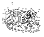
- FIG. 1 is a perspective view of a power shovel according to an exemplary embodiment.
- FIG. 2 is a plan view of the power shovel of FIG. 1 .
- FIG. 3 is a perspective view of a portion of the deck of the power shovel of FIG. 1 .
- FIG. 4 is a perspective view of generators associated with the power shovel of FIG. 1 .
- FIG. 5 is a perspective view of a hydraulic system associated with the power shovel of FIG. 1 .
- FIG. 6 is a flow chart of an energy management system according to an exemplary embodiment.
- FIG. 7 is a schematic diagram of an energy management system in a first configuration according to an exemplary embodiment.
- FIG. 8 is a schematic diagram of the energy management system of FIG. 7 in a second configuration.
- FIG. 9 is a schematic diagram of the energy management system of FIG. 8 in a third configuration.
- FIG. 10 is a graphical representation of prophetic data provided by a simulation according to an exemplary embodiment.
- heavy equipment in the form of a power shovel 110 includes a deck 112 moveable upon tracks 114 .
- the deck 112 further includes a powerhouse 116 , an electronic compartment 118 (e.g., e-house), a hydraulic system 120 , an operator cab 122 , energy storage components 124 , and engine and hydraulic cooling systems 126 , 128 (see FIG. 2 ).
- Various stairwells 130 and walkways 132 may be incorporated with the deck 112 for movement throughout the power shovel 110 .
- Exhaust mufflers 134 are positioned on the deck 112 above the powerhouse 116 and to the rear of the operator cab 122 .
- the power shovel 110 further includes an articulated arm 136 including a boom 138 rotatably coupled to an arm 140 (e.g., stick), which is rotatably coupled to a bucket 142 .
- actuators in the form of hydraulic cylinders, including a boom cylinder 144 , an arm cylinder 146 , and a curl cylinder 148 , extend between the deck 112 and boom 138 to control movement of the boom 138 relative to the deck 112 , between the boom 138 and the arm 140 to control movement of the arm 140 relative to the boom 138 , and between the boom 138 and the bucket 142 to control movement of the bucket 142 relative to the arm 140 .
- the hydraulic cylinders 144 , 146 , 148 are double-acting cylinders, configured to receive hydraulic fluid on both ends of the respective piston. Additional actuators (e.g., electric or hydraulic motors) may be used to propel the power shovel 110 via the tracks 114 , and/or to rotate the deck 112 relative to the tracks 114 .
- the deck 112 includes two energy storage components 124 located proximate to the rear corners of the deck 112 .
- the energy storage components 124 include banks of one or more ultra-capacitors 150 .
- other forms of energy storage components e.g., secondary batteries
- an engine cooler system 126 which may include one or more coolant fans 152 and/or blowers, is positioned between the energy storage components 124 .
- the deck 112 includes the powerhouse 116 in front of the electrical storage components 124 .
- the powerhouse 116 includes two diesel generator sets 154 , each including an engine 156 driving an alternator 158 .
- Rectifiers may be used to convert alternating current provided by the diesel generator sets 154 to direct current for communication to working components of the power shovel 110 via a direct-current bus (see, e.g., bus 320 as shown in FIG. 7 ).
- a direct-current bus see, e.g., bus 320 as shown in FIG. 7 .
- other numbers or types of generators are used, such as a single, gasoline-powered generator set.
- electrical power may be supplied over cables from a standalone power plant.
- the power shovel 110 includes the hydraulic system 120 for converting the electrical energy provided by the powerhouse 116 to energy of pressurized hydraulic fluid.
- the pressurized hydraulic fluid may then be used to drive hydraulic actuators, such as hydraulic cylinders 144 , 146 , 148 and hydraulic motors.
- the hydraulic system 120 includes two groups 160 of six sets 162 of electric motors 164 coupled to hydraulic pumps 166 .
- the pumps 166 are bi-directional, and may provide and receive hydraulic fluid under pressure in two directions.
- the speed and direction of the hydraulic pump 166 is controlled by an electrical drive system 172 (e.g., one or more electrical drives and supporting structure, one or more inverters) stored in the electronic compartment 118 and coupled to the electrical bus (see also inverters 332 , 334 , 336 and bus 320 as shown in FIG. 7 ).
- the electrical drive system 172 selectively supplies power to control the speed, direction, and/or torque of the electric motor 164 , which drives the hydraulic pump 166 .
- the hydraulic system may include other numbers or arrangements of electric motors and hydraulic pumps.
- the sets 162 of hydraulic pumps 166 and electric motors 164 are coupled to a hydraulic valve manifold 168 .
- the hydraulic valve manifold 168 is configured to direct the hydraulic fluid of one or more of the pump and motor sets 162 to and from working components of the power shovel 110 .
- the hydraulic valve manifold 168 is arranged as a matrix, where each pump and motor set 162 may be selectively coupled to each working component.
- the hydraulic valve manifold 168 may couple the hydraulic fluid provided by two or more pumps to the same working component, such as one of the hydraulic cylinders 144 , 146 , 148 .
- the hydraulic valve manifold 168 is positioned between the two groups 160 of pump and motor sets 162 .
- the hydraulic system 120 is further configured for regeneration of energy associated with the hydraulic fluid.
- Surplus energy may be provided by the hydraulic fluid, such as when working components of the power shovel 110 are driven by gravity or momentum. Instead of or in combination with braking, the surplus energy of the hydraulic fluid may be conserved (e.g., reused, preserved, utilized).
- the hydraulic pumps 166 function as hydraulic motors, and are driven by the pressurized hydraulic fluid.
- the hydraulic pumps 166 in turn, drive the electric motors 164 , which generate electricity and provide the electricity to the bus (see, e.g., bus 320 as shown in FIG. 7 ). If not then needed by other working components, the electricity may be stored via the energy storage components 124 .
- the operator cab 122 includes a control computer 170 that uses logic to operate the power shovel 110 in response to and in conjunction with various inputs, including operator commands (e.g., joystick instructions to crowd bucket, raise boom, etc.), environmental conditions (e.g., sensed terrain slope), internal conditions (e.g., hydraulic fluid temperature, available power, etc.), and other factors.
- the control computer 170 operates the electrical drive system 172 positioned in the electronic compartment 118 , which control the flow of electricity (e.g., amperage, voltage, frequency) from the generator sets 154 to the motor and pump sets 162 and other components, such as slew motors 174 and cooling fans 176 for the hydraulic system 120 .
- the slew motors 174 directly control rotation of the deck 112 relative to the tracks 114 , such as during a swing movement of the power shovel 110 .
- an energy management and storage system 210 includes a source 212 of electrical power, an electric motor 214 , and a hydraulic pump 216 .
- the electric motor 214 is further coupled to an electrical storage element 218 .
- the electric motor 214 is configured to receive power from both the electrical power source 212 and the electrical storage element 218 .
- the electric motor 214 is configured to function as a generator and provide electricity to the electrical storage element 218 .
- the electric motor 214 drives the hydraulic pump 216 , which in turn pressurizes hydraulic fluid.
- the hydraulic fluid is controllably routed by way of valves 220 to one or more working components 222 (e.g., attachments) for operation of the working components 222 .
- the hydraulic fluid may be controllably routed through the valves 220 back to the hydraulic pump 216 .
- the hydraulic pump 216 may function as a hydraulic motor, driving the electric motor 214 to operate as a generator.
- the source 212 of electrical power includes a generator set selected based upon output capacity.
- the generator set is run at a substantially constant, optimal speed and power output where the speed or output is optimized for the particular generator set with respect to minimum fuel consumption per power output, maximum life of the generator set per power output, minimum maintenance or downtime of the system 210 , or other such parameters or combinations of such parameters.
- the generator set running at the optimal speed, has an electrical output that is less than an expected power need for the system 210 during portions of a work cycle of the system 210 .
- Additional power from the electrical storage element 218 supplements the power of the generator set, allowing the system 210 to meet momentary power demands, while the generator set to still continuously run at the optimal speed and/or power output.
- the electrical storage element provides at least 20-percent of the power used by the system during a peak demand portion of the work cycle (compare power demand 416 with generator output 412 as shown in FIG. 10 ). During other portions of the work cycle, the generator set may produce surplus power, which may be delivered to the electrical storage element 218 .
- the generator set of the source 212 is selected such that running at optimal speeds the generator set (or sets) provides the total energy used by the system 210 throughout each work cycle.
- the supplemental energy provided by the energy storage element 218 during the higher-demand portions of the work cycle is completely offset by the surplus energy provided by the source 212 during the lower-demand portions of the work cycle.
- Steady-state operation of the generator set at optimal running speeds may not occur during initial cycles of operation for a particular assignment, when the system 210 is moved to a new location, when the system 210 changes tasks, etc. During such times the generator set may be run at above or below optimal speeds.
- the generator set (or sets) is selected such that, at optimal running speeds of the generator set, the source 212 provides less than the total energy used by the system 210 throughout each work cycle. Instead, a portion of the energy required for each work cycle is regenerated from previous work cycles. During initial cycles, the generator set may be run above the optimal power until the capacitor is charged and/or until energy is available from regeneration.
- an energy management and storage system 310 includes a generator set 312 formed from an engine 314 (e.g., internal combustion engine, diesel engine) coupled to an alternator 316 .
- the alternator 316 When driven by the engine 314 , the alternator 316 provides an electrical output that is converted from alternating current to direct current by a rectifier 318 . The electrical output is then provided to a common electrical bus 320 that is in communication with working components of the system 310 .
- the working components include one or more electric motors 322 coupled to one or more hydraulic pumps 324 , one or more additional electric motors 326 , and/or auxiliary components 328 .
- An energy storage component 330 e.g., one or more capacitors
- inverters 332 , 334 , 336 regulate the electricity to and from the electrical bus 320 to each of the working components.
- a state-of-charge controller 338 regulates the electricity to and from the electrical bus 320 to the energy storage component 330 .
- electrical power is supplied from the generator set 312 to the electrical bus 320 , and from the electrical bus 320 to the electric motors 322 , 326 and auxiliary components 328 .
- some of the electricity of the electrical bus 320 is directed to the electrical storage component 330 .
- power is drawn from the electrical storage component 330 to supplement power from the generator set 312 , and is provided to the electric motors 322 , 326 and/or auxiliary components 328 .
- the generator set 312 is run at a substantially constant speed, which produces electricity at a rate below the power required by the motors 322 , 326 and auxiliary components 328 during the higher-demand periods.
- the generator set 312 is sized and configured such that the generator set 312 would be unable to satisfy the power requirements for the higher-demand periods (e.g., expected peak loads) without support from the energy storage component 330 .
- So sizing and configuring the generator set 312 is intended to improve the efficiency of the system 310 by reducing the weight of the system 310 (i.e., having a smaller, lighter engine and alternator) and/or optimizing the fuel consumption of the generator set 312 by running the generator set 312 at an efficient speed and reducing production of surplus electricity.
- the system 310 further allows for regeneration of electricity from the electric motors 322 , 326 (see FIG. 9 ).
- gravity acting upon a work implement e.g., hydraulically actuated articulated arm with bucket
- energy may be communicated to the electric motors 322 by way of hydraulic fluid driving the pump 324 coupled to the motors 322 .
- rotational or translational momentum may be recaptured by way of motors 326 coupled to the rotating or translating portions of the system 310 (e.g., slew motors coupled to the rotatable deck of a power shovel) in place of or in conjunction with friction braking.
- Regeneration of electricity is intended to improve the efficiency of the system and reduce the amount of heat absorbed by the hydraulic system.
- FIG. 10 by way of a graphical representation 410 of prophetic data produced from a simulation of an energy management and storage system for heavy equipment, relationships are illustrated between energy supplied by a generator set 412 , energy held by a bank of ultra-capacitors 414 , and energy demand 416 of the heavy equipment. According to the simulation, three work cycles are shown 418 , 420 , 422 , each lasting for approximately thirty seconds (i.e., about 120 per hour).
- the cycles 418 , 420 , 422 show a substantially repetitive oscillatory demand for energy, where the peak demands 424 exceed the substantially constant rate of electricity produced by the generator set 412 (e.g., by about 50%).
- the energy demand 416 exceeds the production of the generator set 412 , power is drawn from the ultra-capacitors, reducing the amount of energy stored by the ultra-capacitors 414 .
- the energy demand 416 drops below the level of energy production by the generator set 412 , some of the power produced by the generator set is supplied to the ultra-capacitors, recharging the ultra-capacitors. Also during each cycle, the energy demand 416 drops below zero 426 , indicating that energy may be regenerated during a portion of the simulated cycles 418 , 420 , 422 .
- an energy-storage system recaptures energy in one or more hydraulic accumulators, which would then be available as needed to supplement the generator set during peak demand periods.
- a mechanical energy-storage system stores energy in rotating devices of rotational inertia, such as flywheels, or in potential energy of elevated weights. The stored energy would then be released as needed to supplement the main mechanical drives during periods of peak demand.
- various forms of both stationary and mobile heavy equipment include an energy management and storage system, as described above.
- the degree of repetitiveness of a work cycle for the heavy equipment may vary as a function of the particular form of heavy equipment and the particular operation or mission to be performed.
- a cycle is repeated at a faster or slower rate than the example shown in FIG. 10 .
- the work cycle or pattern includes more than one peak or period in which energy from an energy storage component supplements an associated generator set.
Abstract
Description
Claims (20)
Priority Applications (5)
| Application Number | Priority Date | Filing Date | Title |
|---|---|---|---|
| US12/899,375 US8626403B2 (en) | 2010-10-06 | 2010-10-06 | Energy management and storage system |
| PCT/US2011/052950 WO2012047546A2 (en) | 2010-10-06 | 2011-09-23 | Energy management and storage system |
| CA2813392A CA2813392C (en) | 2010-10-06 | 2011-09-23 | Energy management and storage system |
| AU2011312602A AU2011312602B2 (en) | 2010-10-06 | 2011-09-23 | Energy management and storage system |
| US13/246,425 US8606451B2 (en) | 2010-10-06 | 2011-09-27 | Energy system for heavy equipment |
Applications Claiming Priority (1)
| Application Number | Priority Date | Filing Date | Title |
|---|---|---|---|
| US12/899,375 US8626403B2 (en) | 2010-10-06 | 2010-10-06 | Energy management and storage system |
Related Child Applications (1)
| Application Number | Title | Priority Date | Filing Date |
|---|---|---|---|
| US13/246,425 Continuation-In-Part US8606451B2 (en) | 2010-10-06 | 2011-09-27 | Energy system for heavy equipment |
Publications (2)
| Publication Number | Publication Date |
|---|---|
| US20120089279A1 US20120089279A1 (en) | 2012-04-12 |
| US8626403B2 true US8626403B2 (en) | 2014-01-07 |
Family
ID=45925769
Family Applications (1)
| Application Number | Title | Priority Date | Filing Date |
|---|---|---|---|
| US12/899,375 Active 2032-01-26 US8626403B2 (en) | 2010-10-06 | 2010-10-06 | Energy management and storage system |
Country Status (4)
| Country | Link |
|---|---|
| US (1) | US8626403B2 (en) |
| AU (1) | AU2011312602B2 (en) |
| CA (1) | CA2813392C (en) |
| WO (1) | WO2012047546A2 (en) |
Cited By (5)
| Publication number | Priority date | Publication date | Assignee | Title |
|---|---|---|---|---|
| US20150042259A1 (en) * | 2011-12-28 | 2015-02-12 | Doosan Infracore Co., Ltd. | Emergency stop method for hybrid construction equipment and brake control device |
| US20150086315A1 (en) * | 2013-09-24 | 2015-03-26 | Kobelco Construction Machinery Co., Ltd. | Hybrid construction machine |
| US9120387B2 (en) | 2010-10-06 | 2015-09-01 | Caterpillar Global Mining Llc | Energy management system for heavy equipment |
| US9190852B2 (en) | 2012-09-21 | 2015-11-17 | Caterpillar Global Mining Llc | Systems and methods for stabilizing power rate of change within generator based applications |
| US9764634B2 (en) | 2015-05-28 | 2017-09-19 | Joy Global Longview Operations Llc | Mining machine and energy storage system for same |
Families Citing this family (2)
| Publication number | Priority date | Publication date | Assignee | Title |
|---|---|---|---|---|
| US9388689B2 (en) * | 2013-02-01 | 2016-07-12 | Caterpillar Global Mining Llc | Multi-deck mining vehicle |
| US11359351B2 (en) * | 2018-07-02 | 2022-06-14 | Stanley Black & Decker, Inc. | Excavator boom mountable high pressure hydraulic tool including a hydraulic motor driven generator |
Citations (103)
| Publication number | Priority date | Publication date | Assignee | Title |
|---|---|---|---|---|
| US3425574A (en) | 1967-01-25 | 1969-02-04 | Bucyrus Erie Co | Hydraulic power unit for a doubleacting cylinder |
| DE2251904A1 (en) | 1972-10-23 | 1974-04-25 | Weserhuette Ag Eisenwerk | LIMIT LOAD CONTROL FOR HYDRAULIC DRIVES |
| DE2331617A1 (en) | 1973-06-22 | 1975-01-16 | Bosch Gmbh Robert | CONTROL DEVICE FOR HYDROPUMPS |
| US4050478A (en) | 1975-04-23 | 1977-09-27 | International Harvester Company | Combined fixed and variable displacement pump system |
| US4230022A (en) | 1976-10-04 | 1980-10-28 | Caterpillar Tractor Co. | Hydraulic rock breaker circuit for an excavator |
| US4533900A (en) | 1981-02-06 | 1985-08-06 | Bayerische Motoren Werke Aktiengesellschaft | Service-interval display for motor vehicles |
| US4606313A (en) | 1980-10-09 | 1986-08-19 | Hitachi Construction Machinery Co., Ltd. | Method of and system for controlling hydraulic power system |
| DE3611553C1 (en) | 1986-04-07 | 1987-07-23 | Orenstein & Koppel Ag | Arrangement for operating a diesel-hydraulic drive |
| US4875337A (en) | 1986-09-27 | 1989-10-24 | Hitachi Construction Machinery Co., Ltd. | Construction machine dual-dump hydraulic circuit with piloted arm-boom cylinder supply priority switching valves |
| DE4102621A1 (en) | 1991-01-30 | 1992-08-06 | Orenstein & Koppel Ag | HYDROSTATIC DRIVE FOR WORKING MACHINES |
| US5167121A (en) | 1991-06-25 | 1992-12-01 | University Of British Columbia | Proportional hydraulic control |
| US5295353A (en) | 1990-06-06 | 1994-03-22 | Kabushiki Kaisha Komatsu Seisakusho | Controlling arrangement for travelling work vehicle |
| US5303551A (en) | 1991-11-30 | 1994-04-19 | Samsung Heavy Industries Co., Ltd. | Flow rate control apparatus for oil-hydraulic pump |
| US5563351A (en) | 1994-03-31 | 1996-10-08 | Caterpillar Inc. | Method and apparatus for determining pump wear |
| US5673558A (en) | 1994-06-28 | 1997-10-07 | Hitachi Construction Machinery Co., Ltd. | Hydraulic circuit system for hydraulic excavator |
| US5722190A (en) | 1996-03-15 | 1998-03-03 | The Gradall Company | Priority biased load sense hydraulic system for hydraulic excavators |
| US5852934A (en) | 1996-03-30 | 1998-12-29 | Samsung Heavy Industries Co., Ltd. | Fluid joining device for power construction vehicles |
| US5890303A (en) | 1995-12-27 | 1999-04-06 | Hitachi Construction Machinery Co., Ltd. | Hydraulic by-pass circuit for a hydraulic shovel |
| US6005360A (en) | 1995-11-02 | 1999-12-21 | Sme Elettronica Spa | Power unit for the supply of hydraulic actuators |
| US6087945A (en) | 1998-01-08 | 2000-07-11 | Hitachi Construction Machinery Co., Ltd. | Pump failure alarm system for hydraulic working machine |
| US6141629A (en) | 1997-07-16 | 2000-10-31 | Komatsu Ltd. | Method and apparatus for determining machine maintenance due times |
| US6148548A (en) | 1998-06-30 | 2000-11-21 | Kabushiki Kaisha Kobe Seiko Sho | Construction machine |
| US6164069A (en) | 1997-06-23 | 2000-12-26 | Hitachi Construction Machinery Co., Ltd. | Hydraulic drive system for construction machine |
| US6164388A (en) | 1996-10-14 | 2000-12-26 | Itac Ltd. | Electropulse method of holes boring and boring machine |
| US6175217B1 (en) | 1996-12-20 | 2001-01-16 | Manuel Dos Santos Da Ponte | Hybrid generator apparatus |
| US6199307B1 (en) * | 1998-06-01 | 2001-03-13 | Kabushiki Kaisha Kobe Seiko Sho | Battery-powered working machine |
| US6282891B1 (en) | 1999-10-19 | 2001-09-04 | Caterpillar Inc. | Method and system for controlling fluid flow in an electrohydraulic system having multiple hydraulic circuits |
| US6323608B1 (en) | 2000-08-31 | 2001-11-27 | Honda Giken Kogyo Kabushiki Kaisha | Dual voltage battery for a motor vehicle |
| US6326763B1 (en) | 1999-12-20 | 2001-12-04 | General Electric Company | System for controlling power flow in a power bus generally powered from reformer-based fuel cells |
| US6339737B1 (en) | 1998-07-07 | 2002-01-15 | Komatsu Ltd. | Data storage of construction machine and data processor |
| US6422001B1 (en) | 2000-10-10 | 2002-07-23 | Bae Systems Controls Inc. | Regeneration control of particulate filter, particularly in a hybrid electric vehicle |
| US20020104239A1 (en) | 2001-02-06 | 2002-08-08 | Masami Naruse | Hybrid construction equipment |
| US6460332B1 (en) * | 1998-11-04 | 2002-10-08 | Komatsu Ltd. | Pressure oil energy recover/regenation apparatus |
| US20030089557A1 (en) | 2000-03-31 | 2003-05-15 | Thomas Eilinger | Device and method for reducing the power of the supply connection in lift systems |
| US6584769B1 (en) | 1998-06-27 | 2003-07-01 | Lars Bruun | Mobile working machine |
| US6591758B2 (en) | 2001-03-27 | 2003-07-15 | General Electric Company | Hybrid energy locomotive electrical power storage system |
| US6591697B2 (en) | 2001-04-11 | 2003-07-15 | Oakley Henyan | Method for determining pump flow rates using motor torque measurements |
| US6612246B2 (en) | 2001-03-27 | 2003-09-02 | General Electric Company | Hybrid energy locomotive system and method |
| US6635973B1 (en) | 1999-03-31 | 2003-10-21 | Kobelco Construction Machinery Co., Ltd. | Capacitor-equipped working machine |
| US6650091B1 (en) | 2002-05-13 | 2003-11-18 | Luxon Energy Devices Corporation | High current pulse generator |
| US6683389B2 (en) | 2000-06-30 | 2004-01-27 | Capstone Turbine Corporation | Hybrid electric vehicle DC power generation system |
| US20040021441A1 (en) | 2001-04-27 | 2004-02-05 | Masayuki Komiyama | Hybrid vehicle power control apparatus and hybrid construction equipment using the power control apparatus |
| US6708787B2 (en) * | 2001-03-12 | 2004-03-23 | Komatsu Ltd. | Hybrid construction equipment |
| US20040073468A1 (en) | 2002-10-10 | 2004-04-15 | Caterpillar Inc. | System and method of managing a fleet of machines |
| US6725581B2 (en) | 2002-06-04 | 2004-04-27 | Komatsu Ltd. | Construction equipment |
| US6789335B1 (en) * | 1999-03-31 | 2004-09-14 | Kobelco Construction Machinery Co., Ltd. | Shovel |
| US6799424B2 (en) | 2001-11-09 | 2004-10-05 | Nabco, Ltd. | Hydraulic circuit |
| US6810362B2 (en) | 2000-03-31 | 2004-10-26 | Hitachi Construction Machinery Co., Ltd. | Construction machine managing method and system, and arithmetic processing device |
| US6820356B2 (en) * | 2002-06-05 | 2004-11-23 | Komatsu Ltd. | Hybrid powered construction equipment |
| US6832175B2 (en) | 2000-03-31 | 2004-12-14 | Hitachi Construction Machinery Co., Ltd. | Method for managing construction machine, and arithmetic processing apparatus |
| US6870139B2 (en) | 2002-02-11 | 2005-03-22 | The Trustees Of Dartmouth College | Systems and methods for modifying an ice-to-object interface |
| US20050061561A1 (en) | 2003-09-24 | 2005-03-24 | Ford Global Technologies, Llc | Stabilized electric distribution system for use with a vehicle having electric assist |
| US6876098B1 (en) | 2003-09-25 | 2005-04-05 | The United States Of America As Represented By The Administrator Of The Environmental Protection Agency | Methods of operating a series hybrid vehicle |
| US6907384B2 (en) | 2000-03-31 | 2005-06-14 | Hitachi Construction Machinery Co., Ltd. | Method and system for managing construction machine, and arithmetic processing apparatus |
| US20050139399A1 (en) | 2003-12-30 | 2005-06-30 | Hydrogenics Corporation | Hybrid electric propulsion system, hybrid electric power pack and method of optimizing duty cycle |
| US6922990B2 (en) | 2002-11-21 | 2005-08-02 | Komatsu Ltd. | Device arrangement structure for hybrid construction equipment |
| US20050246082A1 (en) * | 2002-12-13 | 2005-11-03 | Shin Caterpillar Mitsubishi Ltd. | Working machine driving unit |
| US6962050B2 (en) * | 2000-05-19 | 2005-11-08 | Komatsu Ltd. | Hybrid machine with hydraulic drive device |
| US20050263331A1 (en) | 2004-05-25 | 2005-12-01 | Tom Sopko | Electric drive system having DC bus voltage control |
| US20060061922A1 (en) | 2004-09-22 | 2006-03-23 | Cellex Power Products, Inc. | Hybrid power supply system having energy storage device protection circuit |
| US7069674B2 (en) | 2002-12-26 | 2006-07-04 | Kubota Corporation | Hydraulic circuit for backhoe |
| US7078825B2 (en) | 2002-06-18 | 2006-07-18 | Ingersoll-Rand Energy Systems Corp. | Microturbine engine system having stand-alone and grid-parallel operating modes |
| US7078877B2 (en) | 2003-08-18 | 2006-07-18 | General Electric Company | Vehicle energy storage system control methods and method for determining battery cycle life projection for heavy duty hybrid vehicle applications |
| US7082758B2 (en) | 2004-05-21 | 2006-08-01 | Komatsu, Ltd. | Hydraulic machine, system for monitoring health of hydraulic machine, and method thereof |
| US7096985B2 (en) | 2001-03-14 | 2006-08-29 | Conception Et Developpement Michelin Sa | Vehicle with a super-capacitor for recovery of energy on braking |
| DE102005017127A1 (en) | 2005-04-14 | 2006-11-09 | Linde Ag | Transport truck for motor vehicle fleet, has sensors connected to monitoring unit that cooperates with adjusting unit of engine and with respective actuating units of drive train of displacement drive and hydraulic pump of working drive |
| US7146808B2 (en) | 2004-10-29 | 2006-12-12 | Caterpillar Inc | Hydraulic system having priority based flow control |
| US7174826B2 (en) | 2004-01-28 | 2007-02-13 | Bucyrus International, Inc. | Hydraulic crowd control mechanism for a mining shovel |
| US7190133B2 (en) | 2004-06-28 | 2007-03-13 | General Electric Company | Energy storage system and method for hybrid propulsion |
| US20070080236A1 (en) | 2005-09-29 | 2007-04-12 | Betz Michael D | Electric powertrain for work machine |
| US20070166168A1 (en) * | 2006-01-16 | 2007-07-19 | Volvo Construction Equipment Ab | Control system for a work machine and method for controlling a hydraulic cylinder in a work machine |
| US7251934B2 (en) | 2004-03-27 | 2007-08-07 | Cnh America Llc | Work vehicle hydraulic system |
| US7252165B1 (en) | 2000-04-26 | 2007-08-07 | Bowling Green State University | Hybrid electric vehicle |
| US7275369B2 (en) | 2004-12-22 | 2007-10-02 | Doosan Infracore Co., Ltd. | Hydraulic control device for controlling a boom-swing frame combined motion in an excavator |
| US20070234718A1 (en) | 2004-07-28 | 2007-10-11 | Volvo Construction Equipment Holding Sweden Ab | Hydraulic System and Work Machine Comprising Such a System |
| US7356991B2 (en) | 2004-12-16 | 2008-04-15 | Doosan Intracore Co., Ltd. | Hydraulic control device of an excavator with improved loading performance on a slope |
| US7386978B2 (en) | 2003-02-20 | 2008-06-17 | Cnh America Llc | Method for controlling a hydraulic system of a mobile working machine |
| US20080157592A1 (en) | 2006-12-29 | 2008-07-03 | Bax Randall L | Electric power generation system with current-controlled power boost |
| US7398012B2 (en) | 2004-05-12 | 2008-07-08 | Siemens Energy & Automation, Inc. | Method for powering mining equipment |
| US7401464B2 (en) | 2003-11-14 | 2008-07-22 | Caterpillar Inc. | Energy regeneration system for machines |
| US7430967B2 (en) | 2001-03-27 | 2008-10-07 | General Electric Company | Multimode hybrid energy railway vehicle system and method |
| US7439631B2 (en) | 2002-01-17 | 2008-10-21 | Komatsu Ltd. | Hybrid power supply system |
| US7444809B2 (en) * | 2006-01-30 | 2008-11-04 | Caterpillar Inc. | Hydraulic regeneration system |
| US7444944B2 (en) | 2005-06-15 | 2008-11-04 | General Electric Company | Multiple engine hybrid locomotive |
| US7448328B2 (en) | 2001-03-27 | 2008-11-11 | General Electric Company | Hybrid energy off highway vehicle electric power storage system and method |
| US20080290842A1 (en) | 2007-05-21 | 2008-11-27 | Nmhg Oregon, Llc | Energy recapture for an industrial vehicle |
| US7479757B2 (en) | 2004-05-27 | 2009-01-20 | Siemens Energy & Automation, Inc. | System and method for a cooling system |
| US20090056324A1 (en) | 2005-05-18 | 2009-03-05 | Yoshiaki Itakura | Hydraulic control device of construction machinery |
| US20090090102A1 (en) | 2006-05-03 | 2009-04-09 | Wilfred Busse | Method of reducing the load of one or more engines in a large hydraulic excavator |
| US7518254B2 (en) | 2005-04-25 | 2009-04-14 | Railpower Technologies Corporation | Multiple prime power source locomotive control |
| US7532960B2 (en) | 2001-03-27 | 2009-05-12 | General Electric Company | Hybrid energy off highway vehicle electric power management system and method |
| US7531916B2 (en) | 2004-05-26 | 2009-05-12 | Altergy Systems, Inc. | Protection circuits for hybrid power systems |
| US7533527B2 (en) | 2004-04-08 | 2009-05-19 | Komatsu Ltd. | Hydraulic drive device for work machine |
| US20090159143A1 (en) | 2006-07-31 | 2009-06-25 | Shin Caterpillar Mitsubishi Ltd. | Fluid pressure circuit |
| US7560904B2 (en) | 2005-10-03 | 2009-07-14 | Lear Corporation | Method and system of managing power distribution in switch based circuits |
| US7571683B2 (en) | 2001-03-27 | 2009-08-11 | General Electric Company | Electrical energy capture system with circuitry for blocking flow of undesirable electrical currents therein |
| US7596893B2 (en) * | 2005-06-06 | 2009-10-06 | Caterpillar Japan Ltd. | Work machine |
| US7628236B1 (en) | 2005-08-01 | 2009-12-08 | Brown Albert W | Manually operated electrical control and installation scheme for electric hybrid vehicles |
| US20100097029A1 (en) | 2008-10-20 | 2010-04-22 | Mccabe Paul Patrick | Energy Storage Module For Load Leveling In Lift Truck Or Other Electrical Vehicle |
| US7730981B2 (en) * | 2005-10-19 | 2010-06-08 | The Raymond Corporation | Lift truck with hybrid power source |
| US20100156180A1 (en) | 2007-06-26 | 2010-06-24 | Sumitomo Heavy Industries Engineering & Services Co., Ltd. | Hybrid power supply device |
| US7748279B2 (en) | 2007-09-28 | 2010-07-06 | Caterpillar Inc | Hydraulics management for bounded implements |
| US20100289443A1 (en) | 2009-05-15 | 2010-11-18 | Joy Mazumdar | Limiting Peak Electrical Power Drawn By Mining Excavators |
-
2010
- 2010-10-06 US US12/899,375 patent/US8626403B2/en active Active
-
2011
- 2011-09-23 AU AU2011312602A patent/AU2011312602B2/en active Active
- 2011-09-23 CA CA2813392A patent/CA2813392C/en active Active
- 2011-09-23 WO PCT/US2011/052950 patent/WO2012047546A2/en active Application Filing
Patent Citations (114)
| Publication number | Priority date | Publication date | Assignee | Title |
|---|---|---|---|---|
| US3425574A (en) | 1967-01-25 | 1969-02-04 | Bucyrus Erie Co | Hydraulic power unit for a doubleacting cylinder |
| DE2251904A1 (en) | 1972-10-23 | 1974-04-25 | Weserhuette Ag Eisenwerk | LIMIT LOAD CONTROL FOR HYDRAULIC DRIVES |
| DE2331617A1 (en) | 1973-06-22 | 1975-01-16 | Bosch Gmbh Robert | CONTROL DEVICE FOR HYDROPUMPS |
| US3891354A (en) | 1973-06-22 | 1975-06-24 | Bosch Gmbh Robert | Regulating system for pumps |
| US4050478A (en) | 1975-04-23 | 1977-09-27 | International Harvester Company | Combined fixed and variable displacement pump system |
| US4230022A (en) | 1976-10-04 | 1980-10-28 | Caterpillar Tractor Co. | Hydraulic rock breaker circuit for an excavator |
| US4606313A (en) | 1980-10-09 | 1986-08-19 | Hitachi Construction Machinery Co., Ltd. | Method of and system for controlling hydraulic power system |
| US4533900A (en) | 1981-02-06 | 1985-08-06 | Bayerische Motoren Werke Aktiengesellschaft | Service-interval display for motor vehicles |
| DE3611553C1 (en) | 1986-04-07 | 1987-07-23 | Orenstein & Koppel Ag | Arrangement for operating a diesel-hydraulic drive |
| US4763473A (en) | 1986-04-07 | 1988-08-16 | O&K Orenstein & Koppel Aktiengesellschaft | Arrangement for operating a diesel hydraulic drive |
| US4875337A (en) | 1986-09-27 | 1989-10-24 | Hitachi Construction Machinery Co., Ltd. | Construction machine dual-dump hydraulic circuit with piloted arm-boom cylinder supply priority switching valves |
| US5295353A (en) | 1990-06-06 | 1994-03-22 | Kabushiki Kaisha Komatsu Seisakusho | Controlling arrangement for travelling work vehicle |
| DE4102621A1 (en) | 1991-01-30 | 1992-08-06 | Orenstein & Koppel Ag | HYDROSTATIC DRIVE FOR WORKING MACHINES |
| US5167121A (en) | 1991-06-25 | 1992-12-01 | University Of British Columbia | Proportional hydraulic control |
| US5303551A (en) | 1991-11-30 | 1994-04-19 | Samsung Heavy Industries Co., Ltd. | Flow rate control apparatus for oil-hydraulic pump |
| US5563351A (en) | 1994-03-31 | 1996-10-08 | Caterpillar Inc. | Method and apparatus for determining pump wear |
| US5673558A (en) | 1994-06-28 | 1997-10-07 | Hitachi Construction Machinery Co., Ltd. | Hydraulic circuit system for hydraulic excavator |
| US6005360A (en) | 1995-11-02 | 1999-12-21 | Sme Elettronica Spa | Power unit for the supply of hydraulic actuators |
| US5890303A (en) | 1995-12-27 | 1999-04-06 | Hitachi Construction Machinery Co., Ltd. | Hydraulic by-pass circuit for a hydraulic shovel |
| US5722190A (en) | 1996-03-15 | 1998-03-03 | The Gradall Company | Priority biased load sense hydraulic system for hydraulic excavators |
| US5852934A (en) | 1996-03-30 | 1998-12-29 | Samsung Heavy Industries Co., Ltd. | Fluid joining device for power construction vehicles |
| US6164388A (en) | 1996-10-14 | 2000-12-26 | Itac Ltd. | Electropulse method of holes boring and boring machine |
| US6175217B1 (en) | 1996-12-20 | 2001-01-16 | Manuel Dos Santos Da Ponte | Hybrid generator apparatus |
| US6164069A (en) | 1997-06-23 | 2000-12-26 | Hitachi Construction Machinery Co., Ltd. | Hydraulic drive system for construction machine |
| US6141629A (en) | 1997-07-16 | 2000-10-31 | Komatsu Ltd. | Method and apparatus for determining machine maintenance due times |
| US6087945A (en) | 1998-01-08 | 2000-07-11 | Hitachi Construction Machinery Co., Ltd. | Pump failure alarm system for hydraulic working machine |
| US6199307B1 (en) * | 1998-06-01 | 2001-03-13 | Kabushiki Kaisha Kobe Seiko Sho | Battery-powered working machine |
| DE69920452T2 (en) | 1998-06-27 | 2005-11-10 | Bruun Ecomate Aktiebolag | MOBILE WORK MACHINE |
| US6584769B1 (en) | 1998-06-27 | 2003-07-01 | Lars Bruun | Mobile working machine |
| US6148548A (en) | 1998-06-30 | 2000-11-21 | Kabushiki Kaisha Kobe Seiko Sho | Construction machine |
| US6339737B1 (en) | 1998-07-07 | 2002-01-15 | Komatsu Ltd. | Data storage of construction machine and data processor |
| US6460332B1 (en) * | 1998-11-04 | 2002-10-08 | Komatsu Ltd. | Pressure oil energy recover/regenation apparatus |
| US6789335B1 (en) * | 1999-03-31 | 2004-09-14 | Kobelco Construction Machinery Co., Ltd. | Shovel |
| US6635973B1 (en) | 1999-03-31 | 2003-10-21 | Kobelco Construction Machinery Co., Ltd. | Capacitor-equipped working machine |
| US6282891B1 (en) | 1999-10-19 | 2001-09-04 | Caterpillar Inc. | Method and system for controlling fluid flow in an electrohydraulic system having multiple hydraulic circuits |
| US6326763B1 (en) | 1999-12-20 | 2001-12-04 | General Electric Company | System for controlling power flow in a power bus generally powered from reformer-based fuel cells |
| US20030089557A1 (en) | 2000-03-31 | 2003-05-15 | Thomas Eilinger | Device and method for reducing the power of the supply connection in lift systems |
| US6907384B2 (en) | 2000-03-31 | 2005-06-14 | Hitachi Construction Machinery Co., Ltd. | Method and system for managing construction machine, and arithmetic processing apparatus |
| US6832175B2 (en) | 2000-03-31 | 2004-12-14 | Hitachi Construction Machinery Co., Ltd. | Method for managing construction machine, and arithmetic processing apparatus |
| US6810362B2 (en) | 2000-03-31 | 2004-10-26 | Hitachi Construction Machinery Co., Ltd. | Construction machine managing method and system, and arithmetic processing device |
| US7252165B1 (en) | 2000-04-26 | 2007-08-07 | Bowling Green State University | Hybrid electric vehicle |
| US6962050B2 (en) * | 2000-05-19 | 2005-11-08 | Komatsu Ltd. | Hybrid machine with hydraulic drive device |
| US6683389B2 (en) | 2000-06-30 | 2004-01-27 | Capstone Turbine Corporation | Hybrid electric vehicle DC power generation system |
| US6323608B1 (en) | 2000-08-31 | 2001-11-27 | Honda Giken Kogyo Kabushiki Kaisha | Dual voltage battery for a motor vehicle |
| US6422001B1 (en) | 2000-10-10 | 2002-07-23 | Bae Systems Controls Inc. | Regeneration control of particulate filter, particularly in a hybrid electric vehicle |
| US20020104239A1 (en) | 2001-02-06 | 2002-08-08 | Masami Naruse | Hybrid construction equipment |
| US6678972B2 (en) * | 2001-02-06 | 2004-01-20 | Komatsu Ltd. | Hybrid construction equipment |
| US6708787B2 (en) * | 2001-03-12 | 2004-03-23 | Komatsu Ltd. | Hybrid construction equipment |
| US7096985B2 (en) | 2001-03-14 | 2006-08-29 | Conception Et Developpement Michelin Sa | Vehicle with a super-capacitor for recovery of energy on braking |
| US7448328B2 (en) | 2001-03-27 | 2008-11-11 | General Electric Company | Hybrid energy off highway vehicle electric power storage system and method |
| US7430967B2 (en) | 2001-03-27 | 2008-10-07 | General Electric Company | Multimode hybrid energy railway vehicle system and method |
| US7532960B2 (en) | 2001-03-27 | 2009-05-12 | General Electric Company | Hybrid energy off highway vehicle electric power management system and method |
| US6591758B2 (en) | 2001-03-27 | 2003-07-15 | General Electric Company | Hybrid energy locomotive electrical power storage system |
| US6612246B2 (en) | 2001-03-27 | 2003-09-02 | General Electric Company | Hybrid energy locomotive system and method |
| US7571683B2 (en) | 2001-03-27 | 2009-08-11 | General Electric Company | Electrical energy capture system with circuitry for blocking flow of undesirable electrical currents therein |
| US6591697B2 (en) | 2001-04-11 | 2003-07-15 | Oakley Henyan | Method for determining pump flow rates using motor torque measurements |
| US20040021441A1 (en) | 2001-04-27 | 2004-02-05 | Masayuki Komiyama | Hybrid vehicle power control apparatus and hybrid construction equipment using the power control apparatus |
| US6864663B2 (en) * | 2001-04-27 | 2005-03-08 | Kobelco Construction Machinery Co., Ltd. | Hybrid vehicle power control apparatus and hybrid construction equipment using the power control apparatus |
| US6799424B2 (en) | 2001-11-09 | 2004-10-05 | Nabco, Ltd. | Hydraulic circuit |
| US7439631B2 (en) | 2002-01-17 | 2008-10-21 | Komatsu Ltd. | Hybrid power supply system |
| US6870139B2 (en) | 2002-02-11 | 2005-03-22 | The Trustees Of Dartmouth College | Systems and methods for modifying an ice-to-object interface |
| US6650091B1 (en) | 2002-05-13 | 2003-11-18 | Luxon Energy Devices Corporation | High current pulse generator |
| US6725581B2 (en) | 2002-06-04 | 2004-04-27 | Komatsu Ltd. | Construction equipment |
| US6820356B2 (en) * | 2002-06-05 | 2004-11-23 | Komatsu Ltd. | Hybrid powered construction equipment |
| US7078825B2 (en) | 2002-06-18 | 2006-07-18 | Ingersoll-Rand Energy Systems Corp. | Microturbine engine system having stand-alone and grid-parallel operating modes |
| US20040073468A1 (en) | 2002-10-10 | 2004-04-15 | Caterpillar Inc. | System and method of managing a fleet of machines |
| US6922990B2 (en) | 2002-11-21 | 2005-08-02 | Komatsu Ltd. | Device arrangement structure for hybrid construction equipment |
| US20050246082A1 (en) * | 2002-12-13 | 2005-11-03 | Shin Caterpillar Mitsubishi Ltd. | Working machine driving unit |
| US7069674B2 (en) | 2002-12-26 | 2006-07-04 | Kubota Corporation | Hydraulic circuit for backhoe |
| US7386978B2 (en) | 2003-02-20 | 2008-06-17 | Cnh America Llc | Method for controlling a hydraulic system of a mobile working machine |
| US7078877B2 (en) | 2003-08-18 | 2006-07-18 | General Electric Company | Vehicle energy storage system control methods and method for determining battery cycle life projection for heavy duty hybrid vehicle applications |
| US20050061561A1 (en) | 2003-09-24 | 2005-03-24 | Ford Global Technologies, Llc | Stabilized electric distribution system for use with a vehicle having electric assist |
| US7258183B2 (en) | 2003-09-24 | 2007-08-21 | Ford Global Technologies, Llc | Stabilized electric distribution system for use with a vehicle having electric assist |
| US6876098B1 (en) | 2003-09-25 | 2005-04-05 | The United States Of America As Represented By The Administrator Of The Environmental Protection Agency | Methods of operating a series hybrid vehicle |
| US7456509B2 (en) | 2003-09-25 | 2008-11-25 | The United States Of America As Represented By The Administrator Of The U.S. Environmental Protection Agency | Methods of operating a series hybrid vehicle |
| US7401464B2 (en) | 2003-11-14 | 2008-07-22 | Caterpillar Inc. | Energy regeneration system for machines |
| US20050139399A1 (en) | 2003-12-30 | 2005-06-30 | Hydrogenics Corporation | Hybrid electric propulsion system, hybrid electric power pack and method of optimizing duty cycle |
| US7174826B2 (en) | 2004-01-28 | 2007-02-13 | Bucyrus International, Inc. | Hydraulic crowd control mechanism for a mining shovel |
| US7251934B2 (en) | 2004-03-27 | 2007-08-07 | Cnh America Llc | Work vehicle hydraulic system |
| US7533527B2 (en) | 2004-04-08 | 2009-05-19 | Komatsu Ltd. | Hydraulic drive device for work machine |
| US7398012B2 (en) | 2004-05-12 | 2008-07-08 | Siemens Energy & Automation, Inc. | Method for powering mining equipment |
| US7082758B2 (en) | 2004-05-21 | 2006-08-01 | Komatsu, Ltd. | Hydraulic machine, system for monitoring health of hydraulic machine, and method thereof |
| US20050263331A1 (en) | 2004-05-25 | 2005-12-01 | Tom Sopko | Electric drive system having DC bus voltage control |
| US7378808B2 (en) | 2004-05-25 | 2008-05-27 | Caterpillar Inc. | Electric drive system having DC bus voltage control |
| US7298102B2 (en) * | 2004-05-25 | 2007-11-20 | Caterpillar Inc | Electric drive system having DC bus voltage control |
| US7531916B2 (en) | 2004-05-26 | 2009-05-12 | Altergy Systems, Inc. | Protection circuits for hybrid power systems |
| US7479757B2 (en) | 2004-05-27 | 2009-01-20 | Siemens Energy & Automation, Inc. | System and method for a cooling system |
| US7190133B2 (en) | 2004-06-28 | 2007-03-13 | General Electric Company | Energy storage system and method for hybrid propulsion |
| US20070234718A1 (en) | 2004-07-28 | 2007-10-11 | Volvo Construction Equipment Holding Sweden Ab | Hydraulic System and Work Machine Comprising Such a System |
| US20060061922A1 (en) | 2004-09-22 | 2006-03-23 | Cellex Power Products, Inc. | Hybrid power supply system having energy storage device protection circuit |
| US7146808B2 (en) | 2004-10-29 | 2006-12-12 | Caterpillar Inc | Hydraulic system having priority based flow control |
| US7356991B2 (en) | 2004-12-16 | 2008-04-15 | Doosan Intracore Co., Ltd. | Hydraulic control device of an excavator with improved loading performance on a slope |
| US7275369B2 (en) | 2004-12-22 | 2007-10-02 | Doosan Infracore Co., Ltd. | Hydraulic control device for controlling a boom-swing frame combined motion in an excavator |
| DE102005017127A1 (en) | 2005-04-14 | 2006-11-09 | Linde Ag | Transport truck for motor vehicle fleet, has sensors connected to monitoring unit that cooperates with adjusting unit of engine and with respective actuating units of drive train of displacement drive and hydraulic pump of working drive |
| US7518254B2 (en) | 2005-04-25 | 2009-04-14 | Railpower Technologies Corporation | Multiple prime power source locomotive control |
| US20090056324A1 (en) | 2005-05-18 | 2009-03-05 | Yoshiaki Itakura | Hydraulic control device of construction machinery |
| US7596893B2 (en) * | 2005-06-06 | 2009-10-06 | Caterpillar Japan Ltd. | Work machine |
| US7444944B2 (en) | 2005-06-15 | 2008-11-04 | General Electric Company | Multiple engine hybrid locomotive |
| US7628236B1 (en) | 2005-08-01 | 2009-12-08 | Brown Albert W | Manually operated electrical control and installation scheme for electric hybrid vehicles |
| US20070080236A1 (en) | 2005-09-29 | 2007-04-12 | Betz Michael D | Electric powertrain for work machine |
| US7560904B2 (en) | 2005-10-03 | 2009-07-14 | Lear Corporation | Method and system of managing power distribution in switch based circuits |
| US7730981B2 (en) * | 2005-10-19 | 2010-06-08 | The Raymond Corporation | Lift truck with hybrid power source |
| US20070166168A1 (en) * | 2006-01-16 | 2007-07-19 | Volvo Construction Equipment Ab | Control system for a work machine and method for controlling a hydraulic cylinder in a work machine |
| US20080295504A1 (en) | 2006-01-16 | 2008-12-04 | Volvo Construction Equipment Ab | Method For Controlling a Hydraulic Cylinder in a Work Machine |
| US7444809B2 (en) * | 2006-01-30 | 2008-11-04 | Caterpillar Inc. | Hydraulic regeneration system |
| US20090090102A1 (en) | 2006-05-03 | 2009-04-09 | Wilfred Busse | Method of reducing the load of one or more engines in a large hydraulic excavator |
| US20090159143A1 (en) | 2006-07-31 | 2009-06-25 | Shin Caterpillar Mitsubishi Ltd. | Fluid pressure circuit |
| US20080157592A1 (en) | 2006-12-29 | 2008-07-03 | Bax Randall L | Electric power generation system with current-controlled power boost |
| US20080290842A1 (en) | 2007-05-21 | 2008-11-27 | Nmhg Oregon, Llc | Energy recapture for an industrial vehicle |
| US8022663B2 (en) * | 2007-05-21 | 2011-09-20 | Nmhg Oregon, Llc | Energy recapture for an industrial vehicle |
| US20100156180A1 (en) | 2007-06-26 | 2010-06-24 | Sumitomo Heavy Industries Engineering & Services Co., Ltd. | Hybrid power supply device |
| US7748279B2 (en) | 2007-09-28 | 2010-07-06 | Caterpillar Inc | Hydraulics management for bounded implements |
| US20100097029A1 (en) | 2008-10-20 | 2010-04-22 | Mccabe Paul Patrick | Energy Storage Module For Load Leveling In Lift Truck Or Other Electrical Vehicle |
| US20100289443A1 (en) | 2009-05-15 | 2010-11-18 | Joy Mazumdar | Limiting Peak Electrical Power Drawn By Mining Excavators |
Non-Patent Citations (6)
| Title |
|---|
| International Search Report and Written Opinion for International Application No. PCT/EP2007/003582, mail date Jan. 30, 2008, 23 pages. |
| International Search Report and Written Opinion for International Application No. PCT/US2010/048257, mail date May 27, 2011, 7 pages. |
| International Search Report and Written Opinion for International Application No. PCT/US2011/052950, mail date Apr. 16, 2012, 7 pages. |
| International Search Report and Written Opinion for International Application No. PCT/US2011/052966, mail date Apr. 10, 2012, 9 pages. |
| International Search Report and Written Opinion for International Application No. PCT/US2011/057491, mail date May 18, 2012, 9 pages. |
| Office Action regarding U.S. Appl. No. 13/246,425, mail date Jun. 27, 2013, 8 pages. |
Cited By (11)
| Publication number | Priority date | Publication date | Assignee | Title |
|---|---|---|---|---|
| US9120387B2 (en) | 2010-10-06 | 2015-09-01 | Caterpillar Global Mining Llc | Energy management system for heavy equipment |
| US20150042259A1 (en) * | 2011-12-28 | 2015-02-12 | Doosan Infracore Co., Ltd. | Emergency stop method for hybrid construction equipment and brake control device |
| US9431930B2 (en) * | 2011-12-28 | 2016-08-30 | Doosan Infracore Co., Ltd. | Emergency stop method for hybrid construction equipment and brake control device |
| US9190852B2 (en) | 2012-09-21 | 2015-11-17 | Caterpillar Global Mining Llc | Systems and methods for stabilizing power rate of change within generator based applications |
| US20150086315A1 (en) * | 2013-09-24 | 2015-03-26 | Kobelco Construction Machinery Co., Ltd. | Hybrid construction machine |
| US9217239B2 (en) * | 2013-09-24 | 2015-12-22 | Kobelco Construction Machinery Co., Ltd. | Hybrid construction machine |
| US9764634B2 (en) | 2015-05-28 | 2017-09-19 | Joy Global Longview Operations Llc | Mining machine and energy storage system for same |
| US9873318B2 (en) | 2015-05-28 | 2018-01-23 | Joy Global Longview Operation LLC | Systems, methods, and apparatuses for storing energy in a mining machine |
| US10377225B2 (en) | 2015-05-28 | 2019-08-13 | Joy Global Longview Operations Llc | Systems, methods, and apparatuses for storing energy in a mining machine |
| US10449849B2 (en) | 2015-05-28 | 2019-10-22 | Joy Global Longview Operations Llc | Mining machine and energy storage system for same |
| US11084367B2 (en) | 2015-05-28 | 2021-08-10 | Joy Global Longview Operations Llc | Mining machine and energy storage system for same |
Also Published As
| Publication number | Publication date |
|---|---|
| WO2012047546A3 (en) | 2012-06-14 |
| US20120089279A1 (en) | 2012-04-12 |
| WO2012047546A2 (en) | 2012-04-12 |
| AU2011312602A1 (en) | 2013-04-11 |
| CA2813392A1 (en) | 2012-04-12 |
| CA2813392C (en) | 2018-10-09 |
| AU2011312602B2 (en) | 2015-09-17 |
Similar Documents
| Publication | Publication Date | Title |
|---|---|---|
| US8606451B2 (en) | Energy system for heavy equipment | |
| US9120387B2 (en) | Energy management system for heavy equipment | |
| CA2813392C (en) | Energy management and storage system | |
| US7658250B2 (en) | Energy storage and recovery for a tracked machine | |
| US8909434B2 (en) | System and method for controlling power in machine having electric and/or hydraulic devices | |
| JP4732284B2 (en) | Hybrid construction machine that converts kinetic energy of inertial body into electrical energy | |
| US8362629B2 (en) | Energy management system for heavy equipment | |
| US20120253610A1 (en) | System and method for controlling power in machine having hydraulic and electric power sources | |
| JP2023535736A (en) | Mechanical configuration and control system that allows interchangeable power supplies | |
| AU2018257609B2 (en) | Energy storage system | |
| Yao et al. | Development of power train of hybrid power excavator | |
| CN116171344A (en) | Machine configuration and control system capable of implementing interchangeable power sources |
Legal Events
| Date | Code | Title | Description |
|---|---|---|---|
| AS | Assignment |
Owner name: BUCYRUS INTERNATIONAL, INC., WISCONSIN Free format text: ASSIGNMENT OF ASSIGNORS INTEREST;ASSIGNORS:ONSAGER, MICHAEL GORDON;HELFRICH, JOSEPH;PERUGINI, DAVE L.;AND OTHERS;SIGNING DATES FROM 20100928 TO 20101005;REEL/FRAME:025109/0883 |
|
| AS | Assignment |
Owner name: CATERPILLAR GLOBAL MINING LLC, WISCONSIN Free format text: CHANGE OF NAME;ASSIGNOR:BUCYRUS INTERNATIONAL, INC.;REEL/FRAME:031294/0886 Effective date: 20110929 |
|
| STCF | Information on status: patent grant |
Free format text: PATENTED CASE |
|
| FPAY | Fee payment |
Year of fee payment: 4 |
|
| MAFP | Maintenance fee payment |
Free format text: PAYMENT OF MAINTENANCE FEE, 8TH YEAR, LARGE ENTITY (ORIGINAL EVENT CODE: M1552); ENTITY STATUS OF PATENT OWNER: LARGE ENTITY Year of fee payment: 8 |