US8620482B2 - Method of estimating the maximum power generation capacity and for controlling a specified power reserve of a single cycle or combined cycle gas turbine power plant, and a power generating system for use with said method - Google Patents
Method of estimating the maximum power generation capacity and for controlling a specified power reserve of a single cycle or combined cycle gas turbine power plant, and a power generating system for use with said method Download PDFInfo
- Publication number
- US8620482B2 US8620482B2 US12/977,523 US97752310A US8620482B2 US 8620482 B2 US8620482 B2 US 8620482B2 US 97752310 A US97752310 A US 97752310A US 8620482 B2 US8620482 B2 US 8620482B2
- Authority
- US
- United States
- Prior art keywords
- gas turbine
- power plant
- generation capacity
- power
- power generation
- Prior art date
- Legal status (The legal status is an assumption and is not a legal conclusion. Google has not performed a legal analysis and makes no representation as to the accuracy of the status listed.)
- Expired - Fee Related, expires
Links
Images


Classifications
-
- F—MECHANICAL ENGINEERING; LIGHTING; HEATING; WEAPONS; BLASTING
- F02—COMBUSTION ENGINES; HOT-GAS OR COMBUSTION-PRODUCT ENGINE PLANTS
- F02C—GAS-TURBINE PLANTS; AIR INTAKES FOR JET-PROPULSION PLANTS; CONTROLLING FUEL SUPPLY IN AIR-BREATHING JET-PROPULSION PLANTS
- F02C9/00—Controlling gas-turbine plants; Controlling fuel supply in air- breathing jet-propulsion plants
-
- F—MECHANICAL ENGINEERING; LIGHTING; HEATING; WEAPONS; BLASTING
- F01—MACHINES OR ENGINES IN GENERAL; ENGINE PLANTS IN GENERAL; STEAM ENGINES
- F01K—STEAM ENGINE PLANTS; STEAM ACCUMULATORS; ENGINE PLANTS NOT OTHERWISE PROVIDED FOR; ENGINES USING SPECIAL WORKING FLUIDS OR CYCLES
- F01K13/00—General layout or general methods of operation of complete plants
- F01K13/02—Controlling, e.g. stopping or starting
-
- F—MECHANICAL ENGINEERING; LIGHTING; HEATING; WEAPONS; BLASTING
- F01—MACHINES OR ENGINES IN GENERAL; ENGINE PLANTS IN GENERAL; STEAM ENGINES
- F01D—NON-POSITIVE DISPLACEMENT MACHINES OR ENGINES, e.g. STEAM TURBINES
- F01D17/00—Regulating or controlling by varying flow
- F01D17/10—Final actuators
- F01D17/12—Final actuators arranged in stator parts
- F01D17/14—Final actuators arranged in stator parts varying effective cross-sectional area of nozzles or guide conduits
- F01D17/16—Final actuators arranged in stator parts varying effective cross-sectional area of nozzles or guide conduits by means of nozzle vanes
-
- F—MECHANICAL ENGINEERING; LIGHTING; HEATING; WEAPONS; BLASTING
- F01—MACHINES OR ENGINES IN GENERAL; ENGINE PLANTS IN GENERAL; STEAM ENGINES
- F01K—STEAM ENGINE PLANTS; STEAM ACCUMULATORS; ENGINE PLANTS NOT OTHERWISE PROVIDED FOR; ENGINES USING SPECIAL WORKING FLUIDS OR CYCLES
- F01K23/00—Plants characterised by more than one engine delivering power external to the plant, the engines being driven by different fluids
- F01K23/02—Plants characterised by more than one engine delivering power external to the plant, the engines being driven by different fluids the engine cycles being thermally coupled
- F01K23/06—Plants characterised by more than one engine delivering power external to the plant, the engines being driven by different fluids the engine cycles being thermally coupled combustion heat from one cycle heating the fluid in another cycle
- F01K23/10—Plants characterised by more than one engine delivering power external to the plant, the engines being driven by different fluids the engine cycles being thermally coupled combustion heat from one cycle heating the fluid in another cycle with exhaust fluid of one cycle heating the fluid in another cycle
-
- F—MECHANICAL ENGINEERING; LIGHTING; HEATING; WEAPONS; BLASTING
- F02—COMBUSTION ENGINES; HOT-GAS OR COMBUSTION-PRODUCT ENGINE PLANTS
- F02C—GAS-TURBINE PLANTS; AIR INTAKES FOR JET-PROPULSION PLANTS; CONTROLLING FUEL SUPPLY IN AIR-BREATHING JET-PROPULSION PLANTS
- F02C1/00—Gas-turbine plants characterised by the use of hot gases or unheated pressurised gases, as the working fluid
- F02C1/007—Gas-turbine plants characterised by the use of hot gases or unheated pressurised gases, as the working fluid combination of cycles
-
- F—MECHANICAL ENGINEERING; LIGHTING; HEATING; WEAPONS; BLASTING
- F22—STEAM GENERATION
- F22B—METHODS OF STEAM GENERATION; STEAM BOILERS
- F22B1/00—Methods of steam generation characterised by form of heating method
- F22B1/02—Methods of steam generation characterised by form of heating method by exploitation of the heat content of hot heat carriers
- F22B1/18—Methods of steam generation characterised by form of heating method by exploitation of the heat content of hot heat carriers the heat carrier being a hot gas, e.g. waste gas such as exhaust gas of internal-combustion engines
- F22B1/1807—Methods of steam generation characterised by form of heating method by exploitation of the heat content of hot heat carriers the heat carrier being a hot gas, e.g. waste gas such as exhaust gas of internal-combustion engines using the exhaust gases of combustion engines
- F22B1/1815—Methods of steam generation characterised by form of heating method by exploitation of the heat content of hot heat carriers the heat carrier being a hot gas, e.g. waste gas such as exhaust gas of internal-combustion engines using the exhaust gases of combustion engines using the exhaust gases of gas-turbines
-
- G—PHYSICS
- G05—CONTROLLING; REGULATING
- G05B—CONTROL OR REGULATING SYSTEMS IN GENERAL; FUNCTIONAL ELEMENTS OF SUCH SYSTEMS; MONITORING OR TESTING ARRANGEMENTS FOR SUCH SYSTEMS OR ELEMENTS
- G05B17/00—Systems involving the use of models or simulators of said systems
- G05B17/02—Systems involving the use of models or simulators of said systems electric
-
- F—MECHANICAL ENGINEERING; LIGHTING; HEATING; WEAPONS; BLASTING
- F05—INDEXING SCHEMES RELATING TO ENGINES OR PUMPS IN VARIOUS SUBCLASSES OF CLASSES F01-F04
- F05D—INDEXING SCHEME FOR ASPECTS RELATING TO NON-POSITIVE-DISPLACEMENT MACHINES OR ENGINES, GAS-TURBINES OR JET-PROPULSION PLANTS
- F05D2270/00—Control
- F05D2270/30—Control parameters, e.g. input parameters
- F05D2270/301—Pressure
-
- F—MECHANICAL ENGINEERING; LIGHTING; HEATING; WEAPONS; BLASTING
- F05—INDEXING SCHEMES RELATING TO ENGINES OR PUMPS IN VARIOUS SUBCLASSES OF CLASSES F01-F04
- F05D—INDEXING SCHEME FOR ASPECTS RELATING TO NON-POSITIVE-DISPLACEMENT MACHINES OR ENGINES, GAS-TURBINES OR JET-PROPULSION PLANTS
- F05D2270/00—Control
- F05D2270/30—Control parameters, e.g. input parameters
- F05D2270/303—Temperature
-
- F—MECHANICAL ENGINEERING; LIGHTING; HEATING; WEAPONS; BLASTING
- F05—INDEXING SCHEMES RELATING TO ENGINES OR PUMPS IN VARIOUS SUBCLASSES OF CLASSES F01-F04
- F05D—INDEXING SCHEME FOR ASPECTS RELATING TO NON-POSITIVE-DISPLACEMENT MACHINES OR ENGINES, GAS-TURBINES OR JET-PROPULSION PLANTS
- F05D2270/00—Control
- F05D2270/40—Type of control system
- F05D2270/44—Type of control system active, predictive, or anticipative
-
- Y—GENERAL TAGGING OF NEW TECHNOLOGICAL DEVELOPMENTS; GENERAL TAGGING OF CROSS-SECTIONAL TECHNOLOGIES SPANNING OVER SEVERAL SECTIONS OF THE IPC; TECHNICAL SUBJECTS COVERED BY FORMER USPC CROSS-REFERENCE ART COLLECTIONS [XRACs] AND DIGESTS
- Y02—TECHNOLOGIES OR APPLICATIONS FOR MITIGATION OR ADAPTATION AGAINST CLIMATE CHANGE
- Y02E—REDUCTION OF GREENHOUSE GAS [GHG] EMISSIONS, RELATED TO ENERGY GENERATION, TRANSMISSION OR DISTRIBUTION
- Y02E20/00—Combustion technologies with mitigation potential
- Y02E20/16—Combined cycle power plant [CCPP], or combined cycle gas turbine [CCGT]
Definitions
- the present disclosure relates to an apparatus and method for estimating the maximum power generation capacity of a single cycle or combined cycle gas turbine power plant on a real-time basis and an apparatus and method for controlling a gas turbine in a single cycle or combined cycle gas turbine power plant such that a specified power reserve of the electric power generator is maintained.
- a combined cycle gas turbine power plant includes components such as a gas turbine, a heat recovery steam generator, a steam turbine, and a generator.
- the gas turbine is employed as prime mover. It can convert the chemical energy of gaseous or liquid fuel into mechanical energy, exhaust enthalpy, and waste heat.
- the exhaust enthalpy can be used to generate steam, which can subsequently be expanded in the steam turbine.
- the steam turbine can produce mechanical power.
- the gas turbine and the steam turbine can be mechanically coupled to a generator.
- the generator can convert the mechanical power into electrical power.
- a variety of different combined cycle power plant configurations exist, for example, single shaft or multi shaft configurations. In a single cycle gas turbine power plant, a gas turbine is used in conjunction with a generator only. The step of recovering the gas turbine's exhaust enthalpy is omitted.
- the electrical power output can be regulated by a control system.
- the power output is the sum of the contribution of the gas turbine and the contribution of the steam turbine.
- the steam turbine can be operated in sliding pressure mode. If the steam turbine is operated in sliding pressure mode, the power output of the plant can be determined by the prevailing operating conditions of the gas turbine.
- the gas turbine can be controlled by a load/temperature controller.
- the load/temperature controller receives a load set-point (for example, the manual load set-point entered by the operator) and commands the input variables to the gas turbine (for example, the position of the variable inlet guide vanes, the (mixed) turbine inlet temperatures, the turbine outlet temperature(s)) such that the desired power output can result.
- the manipulated variables can be adjusted within a predefined range and according to a given operation concept.
- the load/temperature controller may consider additional operation limits. These limits can arise from limiting values of selected power plant process quantities (for example, maximum/minimum temperatures or pressures). Maximum power output (also referred to as base load) results when the manipulated variables take their base load values.
- the power generated by the plant can be sold to a customer and delivered to the electrical grid for distribution.
- the maximum power generation capacity is generally unknown because it is highly dependent on the ambient conditions at the power plant (for example, ambient temperature, ambient pressure, ambient humidity) and other variable factors, such as fuel type and quality (for example, caloric value), heat soaking of the components, aging, dirt.
- Knowledge about the maximum power generation capacity is not only valuable for dispatching but can be similarly useful when the power plant operator is asked by the customer (or is contractually obliged by the grid authority) to maintain a specified power capacity in reserve.
- a power reserve is, for example, used in order to provide frequency support.
- the specification of the power reserve may involve a static requirement (for example, to provide a power capacity of a given MW figure) as well as a transient requirement (for example, to provide the power capacity with a minimum average loading gradient).
- the specification can be formulated in terms of a desired power capacity and a desired maximum time within which the desired power capacity has to be provided.
- a controller that operates a gas turbine such that a desired power generation capacity can be maintained in reserve.
- the inlet guide vane angle of the compressor is applied as an indicator of the reserve capacity of the gas turbine.
- the proposed controller can continuously compare the actual inlet guide vane angle to an intended inlet guide vane angle that corresponds to a desired reserve capacity.
- a controller can adjust the fuel flow to the gas turbine to adjust the turbine output power and thereby maintain the actual inlet guide vane angle at the intended value corresponding to the desired reserve capacity.
- the power output of the gas turbine generator is independent of the manual load set-point on a long-term basis. As a consequence, the gas turbine generator cannot be operated at a settable load while the reserve capacity controller is active.
- the inlet guide vane angle is proposed to be a good indicator of the reserve capacity of the gas turbine. This correlation is assumed to be relatively independent of disturbances, such as changing ambient conditions. However, the bandwidth of the inlet guide vane controller has to be set comparably small in order not to interfere with the control actions of the speed/load governor. As a consequence, only low-frequency disturbances are rejected.
- a method of estimating the maximum power generation capacity of a gas turbine power plant is disclosed.
- a controller regulates an operation of the power plant.
- the method includes calculating an actual power output and a maximum power generation capacity of the gas turbine power plant based on a mathematical model of the gas turbine power plant, measuring the actual power output of the gas turbine power plant, comparing the calculated actual power output and the measured power output to derive a model-estimation error, processing the model-estimation error to generate a correction signal, and applying the correction signal to the calculated maximum power generation capacity to obtain a corrected estimate of the maximum power generation capacity of the gas turbine power plant.
- a method for controlling a specified power reserve of a gas turbine power plant is disclosed.
- An input means generates a load set-point signal for the gas turbine power plant.
- a controller receives the load set-point signal and regulates a power output of the gas turbine power plant.
- the method includes continuously updating an estimate of the maximum power generation capacity of the gas turbine power plant, calculating a load offset by specifying a power reserve and determining the load offset from the specified power reserve, calculating a load limit as a difference of the estimate of the maximum power generation capacity and the load offset, and applying the load limit as an upper limit of the load set-point signal to obtain a limited load set-point signal.
- a power generating system including a gas turbine power plant is disclosed.
- a controller regulates operation of the gas turbine power plant.
- An estimation unit calculates an actual power output and a maximum power generation capacity of the gas turbine power plant based on a mathematical model of the gas turbine power plant, measures the actual power output of the gas turbine power plant, compares the calculated actual power output and the measured power output to derive a model-estimation error, processes the model-estimation error to generate a correction signal, applies the correction signal to the calculated maximum power generation capacity to obtain a corrected estimate of the maximum power generation capacity of the gas turbine power plant, and continuously provides an estimate of the maximum power generation capacity of the gas turbine power plant.
- a power generating system including a gas turbine power plant.
- An input means generates a load set-point signal for the gas turbine power plant.
- a controller receives the load set-point signal and regulates the power output of the gas turbine power plant.
- An input means specifies a power reserve. The controller operates the gas turbine power plant such that the specified power reserve is maintained, uses a continuously updated estimate of the maximum power generation capacity of the gas turbine power plant, calculates a load offset by specifying a power reserve and for determining the load offset from the specified power reserve, calculates a load limit as a difference of the estimate of the maximum power generation capacity and the load offset, and applies the limit as an upper limit of the load set-point signal to obtain a limited load set-point signal.
- FIG. 1 shows in a block control diagram the elements of an exemplary embodiment of the disclosure
- FIG. 2 shows in a block control diagram the internal structure of an exemplary embodiment of the disclosure
- FIG. 3 shows in a block control diagram the load/temperature control of a combined cycle power plant with an exemplary embodiment of the disclosure.
- FIG. 4 shows in a schematic, the response, of a combined cycle power plant of an exemplary embodiment of the disclosure with the steam turbine in sliding pressure mode, to a step in the commanded load.
- Exemplary embodiments of the disclosure relate to a method of estimating the maximum power generation capacity of a single cycle or combined cycle gas turbine power plant, and to a power generating system including a single cycle or combined cycle power plant and an estimation unit for estimating on a real-time basis the maximum power generation capacity of the power plant.
- An exemplary embodiment of the disclosure relates to a method for operating a single cycle or combined cycle gas turbine power plant such that a specified power reserve can be maintained.
- An exemplary embodiment of the disclosure relates to a power generating system including a single cycle or combined cycle power plant and a control apparatus that operates the power plant such that a specified power reserve can be maintained.
- the method can include:
- the mathematical model 111 can be a control-oriented and dynamic representation of the process.
- the model can consider commands of the load/temperature controller, the influence of measurable disturbances, and the existence of operational limits.
- Load/temperature controller inputs can be used in the model to calculate the actual power output.
- Measured disturbance signals can be used in the model to consider the influence of various disturbances on the actual power output and the maximum power generation capacity.
- Power plant process measurements can be used in the model to include the impact of different operating limits on the calculation of the maximum power generation capacity.
- steps (1c), (1d), and (1e) The influence of non-measured disturbances can be accounted for within steps (1c), (1d), and (1e), where in step (1d) a separation of low-frequency effects and high-frequency effects can be possible.
- step (1d) a separation of low-frequency effects and high-frequency effects can be possible.
- the input vector to the mathematical model 111 can include signals such as the commanded position of variable inlet guide vanes, the commanded mixed turbine inlet temperature(s), the measured gas turbine compressor inlet temperature, the measured coolant temperature of the steam turbine condenser, information about the fuel type, information about the fuel quality, feedback signals from power augmentation measures, the measured gas turbine compressor outlet temperature, the measured gas turbine compressor outlet pressure, and the measured turbine exhaust temperature.
- step (1c) can be implemented by calculating the quotient of the measured power output 204 and the calculated actual power output 113 , yielding a multiplicative model-estimation error 124 .
- step (1e) the calculated maximum power generation capacity 112 can then be multiplied by the correction signal 125 to obtain a corrected estimate of the maximum power generation capacity 126 of the single cycle or combined cycle gas turbine power plant.
- step (1c) can be implemented by calculating the difference of the measured power output 204 and the calculated actual power output 113 , yielding an additive model-estimation error 124 .
- the correction signal 125 can then be added to the calculated maximum power generation capacity 112 to obtain a corrected estimate of the maximum power generation capacity 126 of the single cycle or combined cycle gas turbine power plant.
- the model-estimation error 124 can be separated by dynamic filtering into a low-frequency part and a high-frequency part, where the low-frequency part can subsequently be used as correction signal 125 .
- the method can include:
- the exemplary method for controlling a specified power reserve can perform the power reserve control action on a control-hierarchic level of load commands.
- a reference load is an estimate of the maximum power generation capacity. This value can be calculated as described above by estimating the maximum power generation capacity of a single cycle or combined cycle power plant. If the power reserve controller is enabled, the manual load set-point is limited by the load limit and the specified power reserve can be maintained. This approach allows the power plant to be operated at a settable load even if the power reserve controller is active (provided that the manual load set-point is smaller than the calculated load limit). Further, no assumption about the temporal behaviour of the grid frequency is necessary, because frequency response action does not bias the calculation of the power reserve load limits.
- the calculation of a load offset in step (2b) can be used in order to account for possible slow components in the power response. Slow components that do not meet the transient power reserve specification can be held in reserve on top of the specified reserve capacity.
- the load offset 132 can be calculated based on a desired power capacity 221 a , a transient requirement 221 b (such as a desired minimum average power reserve loading gradient or a desired maximum time within which the desired power capacity has to be provided), an input vector, which may include load/temperature controller commands 211 , measured disturbance signals 201 , and power plant process measurements 203 , further based on the estimate 126 of the maximum power generation capacity, and on model assumptions.
- the desired power capacity 221 a may be specified as absolute figure (in MW) or as a fixed percentage of the maximum power generation capacity.
- the exemplary embodiment can be implemented for a combined cycle power plant with a gas turbine with sequential combustion.
- the method of estimating the maximum power generation capacity is explained hereafter as part of the method for controlling a specified power capacity.
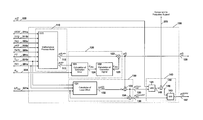
- FIG. 2 a block diagram of the internal structure of an exemplary embodiment 100 of the power reserve controller is shown.
- the controller includes of four major units.
- a model-based estimation unit 110 a measurement-based correction unit 120 , a unit 130 for the calculation of the power reserve load limits, and a unit 140 which processes the load limits.
- Key functions of the units 110 , 120 , 130 , and 140 are:
- the unit 110 involves a mathematical process model 111 .
- the mathematical model is control-oriented, hence a concise description of the system is given.
- the mathematical model 111 can use the disturbance signals 201 a (TK1) and 201 b (T CLT ), the load controller commands 211 a (VIGV) and 211 b (TIT2), information about the fuel type 201 c (FT), and the power plant process measurements 203 a , 203 b , and 203 c (TK2, pK2, TAT2) to assess the current power output of the plant 112 (P CC BL,mbe ) and the maximum power generation capacity 113 (P CC mbe ).
- a correction signal ⁇ Misc can be determined in unit 120 .
- This correction signal can subsequently be used to update the calculated value 112 (P CC BL,mbe ), yielding an adapted estimate 126 (P CC BL ) of the maximum power generation capacity of the plant.
- the estimate 126 (P CC BL ) can be used internally but also provided as an output of the power reserve controller.
- a load offset 132 ( ⁇ P PRC CC ) can be calculated in 131 and subsequently subtracted 133 from the estimated maximum power generation capacity 126 (P CC BL ).
- the resulting load signal 135 (P PRC CC,Lim ) can be used in unit 140 as power reserve load limit.
- the signal 136 (P PRC CC,Lim,KDF ) is the sum 134 of the limit 133 (P PRC CC,Lim ) and the desired power capacity 221 a ( ⁇ P PRC ). It is processed in unit 140 to cap 143 the final power reserve load command 147 (P CC SP,PRC ).
- the load range between the limits 135 (P PRC CC,Lim ) and 136 (P PRC CC,Lim,KDF ) is reserved for frequency support 225 .
- FIG. 3 shows a schematic of the integration of an exemplary embodiment of the power reserve controller (including the units 110 , 120 , 130 , 140 ) into the control logic of a combined cycle gas turbine power plant 200 .
- the signals used in the power reserve controller can include the control variables 211 a (VIGV) and 211 b (TIT2) of the load/temperature controller 210 , information about the fuel type 201 c (FT), the measurable disturbance signals 201 a and 201 b (TK1 and T CLT ), the power plant process measurements 203 (TK2, pK2, TAT2), the measured power output 204 (P CC ), and the desired power capacity 221 a ( ⁇ P PRC ).
- the power reserve controller can limit the manual load set-point 222 (P CC SP ) to the power reserve control load margin 135 (P PRC CC,Lim ). This can be accomplished with the minimum value selector 141 .
- the resulting reserve in power capacity can be provided for frequency support.
- the load component for frequency support 225 can be determined from a frequency deviation 223 ( ⁇ f) and a power gain factor 224 (K).
- the component 225 can be added at the summation node 142 .
- Frequency support is limited 143 at the load margin 136 (P PRC CC,Lim,KDF ).
- the final load command 147 (P CC SP,PRC ) can eventually be fed to the load/temperature controller 210 .
- the individual contributions of the gas turbine and of the steam turbine to the overall power output can be assessed separately.
- the parameter P GT Nom is a nominal base load power output, which can be calculated for a reference set of ambient and boundary conditions.
- the three functions ⁇ TK1 (TK1), ⁇ VIGV (VIGV), and ⁇ TIT2 (TIT2) can be used to scale the nominal power output.
- the first factor corrects the nominal power output for changing compressor inlet temperatures, TK1.
- the factors ⁇ VIGV (VIGV) and ⁇ TIT2 (TIT2) approximate the relative influence on the gas turbine power output of the position of the variable inlet guide vanes, VIGV, and of the mixed inlet temperature of the low pressure turbine, TIT2. Additionally, the factors ⁇ VIGV (VIGV) and ⁇ TIT2 (TIT2) are functions of the fuel type used, FT.
- the quasi-static function (1) can be augmented in this aspect of the mathematical model with a first-order element of time constant ⁇ PWR GT , to obtain an estimation P GT mbe of the actual gas turbine power output.
- P GT mbe ⁇ PWR GT ( s ) ⁇ P GT QS,mbe (2)
- the steam turbine power output and the gas turbine power output are coupled, because the power output of the steam turbine is a function of the gas turbine exhaust enthalpy flow rate.
- the power output of the steam turbine, P ST mbe can be defined as a dynamic function of the control variables VIGV and TIT2 and of the steam turbine condenser inlet temperature, T CLT .
- the total power output of the combined cycle system, P CC mbe simply results as the sum of the component's power outputs, P GT ,mbe and P ST mbe , respectively.
- P CC mbe P GT mbe +P ST mbe (4)
- the base load values of the control signals VIGV and TIT2 have to be known. During operation, these base load positions are continuously computed and adjusted by the load/temperature controller.
- the base load value of VIGV can be a function of the type of fuel used, FT, of the compressor outlet temperature, TK2, and of the compressor outlet pressure, pK2.
- the base load value of TIT2 can be dependent on the compressor intake temperature, TK1, the fuel type used, FT, the base load position of VIGV, and the operating limit of the low pressure turbine outlet temperature, TAT2. Correlations between TK2, pK2, TAT2 and VIGV, and between TAT2 and TIT2 were derived.
- the power output of a combined cycle power plant can be subject to numerous disturbances, such as varying ambient conditions, changing operating conditions or transient system states. Some of these effects do not enter the model equations.
- feedback information from the system is retrieved. Accessible information can be contained in the measurement of the actual combined cycle power output, P CC . If the disturbances are assumed to be of “multiplicative form,” the model-estimation error is given by the following quotient:
- the quotient ⁇ circumflex over ( ⁇ ) ⁇ Misc captures high-frequency as well as low-frequency modelling errors.
- the high-frequency part can stem from deviations in the modelled gas turbine load dynamics or are the result of measurement noise.
- Low-frequency disturbances can originate from slow dynamics, for example, thermal transients, ageing, or changing ambient conditions.
- the disturbances are separated into low-frequency and high-frequency contributions by applying a filter operation to the quotient ⁇ circumflex over ( ⁇ ) ⁇ Misc .
- the low-frequency disturbances are extracted as
- ⁇ Y Misc 1 T ADPT ⁇ s + 1 ⁇ Y ⁇ Misc .
- the parameter ⁇ ADPT is the time constant of a low-pass filter.
- the frequency (2 ⁇ ADPT ) ⁇ 1 separates the “slow” from the “fast” disturbances.
- the calculated maximum power generation capacity is only corrected for the slow disturbances.
- the resulting quantity, P CC BL is the corrected estimate of the maximum power generation capacity of the combined cycle power plant.
- the estimated maximum power generation capacity can be used by the power reserve controller as a reference load. From this reference load, a required load offset can be subtracted to obtain the power reserve load limit.
- the calculation of the load offset can be based on the specification of the power reserve and on model assumptions concerning the dynamic properties of components involved.
- the specification of the power reserve can involve a static requirement as well as a transient requirement.
- the static requirement can be defined so as to provide a desired power capacity of a given MW figure.
- the transient requirement can be defined in terms of a desired minimum average loading gradient.
- FIG. 4 a response of the plant power output 401 to a step in the commanded load is sketched. Due to internal dynamics, the power plant is not able to immediately follow an increase in demanded power.
- the power response includes a fast part 402 (contribution of the gas turbine) and a slow part 403 (contribution of the steam turbine). Also shown in FIG. 4 are the power reserve specifications 410 , 411 a , and 411 b .
- the transient requirements necessitate the controller to keep in reserve a total power capacity 420 that is larger than the power capacity specified 410 . If the transient requirement is stringent, the required loading gradient can be met only by the gas turbine.
- the desired power capacity can be assumed to be provided exclusively by the gas turbine. Accordingly, the load offset 420 ( ⁇ P PRC CC ) follows as
- ⁇ P PRC is the specified power capacity 410
- ⁇ P GT QS the contribution of the gas turbine 402
- ⁇ P ST QS the contribution of the steam turbine 403 .
- the controller 100 and its constituent elements can be implemented on a microprocessor coupled to a memory. All the method steps described herein may be performed on a microprocessor coupled to a memory.
- TAT2 Measured turbine exhaust temperature of low pressure turbine (° C.)
- TIT2 Commanded mixed turbine inlet temperature of low pressure turbine (° C.)
- T CLT Measured coolant temperature of steam turbine condenser (° C.)
Abstract
Description
-
- (1a) calculating the actual power output (the expected power output at the current operating point) 113 and the expected maximum
power generation capacity 112 based on amathematical model 111 of the single cycle or combined cycle gas turbine power plant. The calculation can rely on an input vector, which may include load/temperature controller commands 211, measured disturbance signals 201, and powerplant process measurements 203; - (1b) measuring the actual power output of the single cycle or combined cycle gas turbine power plant;
- (1c) comparing the calculated
actual power output 113 and the measuredpower output 204 to derive a model-estimation error 124; - (1d) processing the model-
estimation error 124 to generate acorrection signal 125; and - (1e) applying 123 the
correction signal 125 to the calculated maximumpower generation capacity 112 to obtain a corrected estimate of the maximumpower generation capacity 126 of the single cycle or combined cycle gas turbine power plant.
- (1a) calculating the actual power output (the expected power output at the current operating point) 113 and the expected maximum
-
- (2a) using an
estimate 126 of the maximum power generation capacity of the single cycle or combined cycle gas turbine power plant as reference; - (2b) calculating a load offset 132 based on the specification of a power reserve, where the specification includes a
static requirement 221 a and atransient requirement 221 b; - (2c) calculating a
load limit 135 as the estimated maximumpower generation capacity 126 minus the load offset 132; - (2d) calculating a
load limit 136 as the sum of thelimit 135 and the desiredpower capacity 221 a; - (2e) applying
limit 135 as an upper limit of the manual load set-point 222 to yield a (limited) load set-point signal 145; - (2f) optionally applying (switch 144) the
limit 136 as an upper limit of theload command 146 which is the (limited) manual load set-point 145 plus theload component 225 for frequency support; and - (2g) feeding the resulting
load command 147 to the input of a conventional load controller.
- (2a) using an
-
- model-based
estimation unit 110 for continuous calculation of the maximum power generation capacity of the plant 112 (PCC BL,mbe), and of the actual power output of the plant 113 (PCC mbe); - measurement-based correction (adaptation)
unit 120 for correction of the calculated maximum power generation capacity 112 (PCC BL,mbe) in order to account for the influence of non-measured disturbances and modelling errors; - power reserve load limits
calculation unit 130 for calculation of the power reserve load limits 135 and 136 (PPRC CC,Lim and PPRC CC,Lim,KDF); - load limits
processing unit 140 for processing of the load limits 135 and 136 to obtain the load command 147 (PCC SP,PRC), that is subsequently fed to the input of a load controller.
- model-based
P GT QS,mbe =P GT Nom·γTK1(TK1)·γVIGV(VIGV)·γTIT2(TIT2) (1)
P GT mbe=ΣPWR GT(s)·P GT QS,mbe (2)
P CC mbe =P GT mbe +P ST mbe (4)
The parameter τADPT is the time constant of a low-pass filter. The frequency (2π·τADPT)−1 separates the “slow” from the “fast” disturbances. The calculated maximum power generation capacity is only corrected for the slow disturbances. This model adaptation is performed by the multiplication of the model-based estimate, PCC BL,mbe, with the correction signal γMisc,
P CC BL=γMisc ·P CC BL,mbe. (7)
where ΔPPRC is the specified
P PRC CC,Lim =P CC BL −ΔP PRC CC (9)
and the optional second limit for the load command follows as
P PRC CC,Lim,KDF =P PRC CC,Lim.KDF +ΔP PRC. (10)
Claims (17)
Priority Applications (1)
| Application Number | Priority Date | Filing Date | Title |
|---|---|---|---|
| US13/683,359 US8700223B2 (en) | 2008-06-26 | 2012-11-21 | Method of estimating the maximum power generation capacity and for controlling a specified power reserve of a single cycle or combined cycle gas turbine power plant, and a power generating system for use with said method |
Applications Claiming Priority (7)
| Application Number | Priority Date | Filing Date | Title |
|---|---|---|---|
| DE102008002660A DE102008002660A1 (en) | 2008-06-26 | 2008-06-26 | Method of estimating maximum power generation capacity of e.g. single-cycle type gas turbine power plant, involves deriving model-estimation error and processing the error to generate correction signal |
| DE102008002660 | 2008-06-26 | ||
| DE102008002660.3 | 2008-06-26 | ||
| CH1278/08 | 2008-08-14 | ||
| CH01278/08A CH699324A1 (en) | 2008-08-14 | 2008-08-14 | Method of estimating maximum power generation capacity of e.g. single-cycle type gas turbine power plant, involves deriving model-estimation error and processing the error to generate correction signal |
| CH01278/08 | 2008-08-14 | ||
| PCT/EP2009/057444 WO2009156299A2 (en) | 2008-06-26 | 2009-06-16 | A method of estimating the maximum power generation capacity and for controlling a specified power reserve of a single cycle or combined cycle gas turbine power plant, and a power generating system for use with said method |
Related Parent Applications (1)
| Application Number | Title | Priority Date | Filing Date |
|---|---|---|---|
| PCT/EP2009/057444 Continuation WO2009156299A2 (en) | 2008-06-26 | 2009-06-16 | A method of estimating the maximum power generation capacity and for controlling a specified power reserve of a single cycle or combined cycle gas turbine power plant, and a power generating system for use with said method |
Related Child Applications (1)
| Application Number | Title | Priority Date | Filing Date |
|---|---|---|---|
| US13/683,359 Division US8700223B2 (en) | 2008-06-26 | 2012-11-21 | Method of estimating the maximum power generation capacity and for controlling a specified power reserve of a single cycle or combined cycle gas turbine power plant, and a power generating system for use with said method |
Publications (2)
| Publication Number | Publication Date |
|---|---|
| US20110160979A1 US20110160979A1 (en) | 2011-06-30 |
| US8620482B2 true US8620482B2 (en) | 2013-12-31 |
Family
ID=43596938
Family Applications (2)
| Application Number | Title | Priority Date | Filing Date |
|---|---|---|---|
| US12/977,523 Expired - Fee Related US8620482B2 (en) | 2008-06-26 | 2010-12-23 | Method of estimating the maximum power generation capacity and for controlling a specified power reserve of a single cycle or combined cycle gas turbine power plant, and a power generating system for use with said method |
| US13/683,359 Expired - Fee Related US8700223B2 (en) | 2008-06-26 | 2012-11-21 | Method of estimating the maximum power generation capacity and for controlling a specified power reserve of a single cycle or combined cycle gas turbine power plant, and a power generating system for use with said method |
Family Applications After (1)
| Application Number | Title | Priority Date | Filing Date |
|---|---|---|---|
| US13/683,359 Expired - Fee Related US8700223B2 (en) | 2008-06-26 | 2012-11-21 | Method of estimating the maximum power generation capacity and for controlling a specified power reserve of a single cycle or combined cycle gas turbine power plant, and a power generating system for use with said method |
Country Status (4)
| Country | Link |
|---|---|
| US (2) | US8620482B2 (en) |
| EP (1) | EP2297622B1 (en) |
| JP (2) | JP5550645B2 (en) |
| WO (1) | WO2009156299A2 (en) |
Cited By (9)
| Publication number | Priority date | Publication date | Assignee | Title |
|---|---|---|---|---|
| US20130238149A2 (en) * | 2009-11-09 | 2013-09-12 | Exergy Limited | System and method for maximising thermal efficiency of a power plant |
| US9404426B2 (en) | 2013-12-31 | 2016-08-02 | General Electric Company | Methods and systems for enhancing control of power plant generating units |
| US9926852B2 (en) | 2015-03-03 | 2018-03-27 | General Electric Company | Methods and systems for enhancing control of power plant generating units |
| US9932907B2 (en) | 2015-03-03 | 2018-04-03 | General Electric Company | Methods and systems for enhancing control of power plant generating units |
| US9945264B2 (en) | 2013-12-31 | 2018-04-17 | General Electric Company | Methods and systems for enhancing control of power plant generating units |
| US9960598B2 (en) | 2015-03-03 | 2018-05-01 | General Electric Company | Methods and systems for enhancing control of power plant generating units |
| US9957843B2 (en) | 2013-12-31 | 2018-05-01 | General Electric Company | Methods and systems for enhancing control of power plant generating units |
| US10287988B2 (en) | 2015-03-27 | 2019-05-14 | General Electric Company | Methods and systems for enhancing operation of power plant generating units and systems |
| US10534328B2 (en) | 2016-06-21 | 2020-01-14 | General Electric Company | Methods and systems for enhancing control of power plant generating units |
Families Citing this family (35)
| Publication number | Priority date | Publication date | Assignee | Title |
|---|---|---|---|---|
| US9354618B2 (en) | 2009-05-08 | 2016-05-31 | Gas Turbine Efficiency Sweden Ab | Automated tuning of multiple fuel gas turbine combustion systems |
| US9671797B2 (en) | 2009-05-08 | 2017-06-06 | Gas Turbine Efficiency Sweden Ab | Optimization of gas turbine combustion systems low load performance on simple cycle and heat recovery steam generator applications |
| US8437941B2 (en) | 2009-05-08 | 2013-05-07 | Gas Turbine Efficiency Sweden Ab | Automated tuning of gas turbine combustion systems |
| US9267443B2 (en) | 2009-05-08 | 2016-02-23 | Gas Turbine Efficiency Sweden Ab | Automated tuning of gas turbine combustion systems |
| DE102010025916B4 (en) * | 2010-07-02 | 2013-10-10 | Siemens Aktiengesellschaft | Method and device for determining model parameters for controlling a steam power plant unit, regulating device for a steam generator and computer program product |
| ITMI20101428A1 (en) * | 2010-07-29 | 2012-01-30 | Ansaldo Energia Spa | METHOD FOR THE MANAGEMENT OF THE PRIMARY RESERVE MARGIN IN A PLANT FOR THE PRODUCTION OF ELECTRICITY AND PLANT FOR THE PRODUCTION OF ELECTRICITY |
| EP3141726B1 (en) * | 2010-08-05 | 2019-10-09 | Mitsubishi Hitachi Power Systems, Ltd. | Combustor and the method of fuel supply and converting fuel nozzle for advanced humid air turbine |
| US8639480B2 (en) | 2010-09-20 | 2014-01-28 | General Electric Company | Methods and systems for modeling turbine operation |
| US8532834B2 (en) * | 2010-10-29 | 2013-09-10 | Hatch Ltd. | Method for integrating controls for captive power generation facilities with controls for metallurgical facilities |
| US8843240B2 (en) * | 2010-11-30 | 2014-09-23 | General Electric Company | Loading a steam turbine based on flow and temperature ramping rates |
| US9458734B2 (en) * | 2012-06-08 | 2016-10-04 | General Electric Company | Model and simulation based control of turbines |
| US9014945B2 (en) * | 2013-03-08 | 2015-04-21 | General Electric Company | Online enhancement for improved gas turbine performance |
| WO2014158237A2 (en) | 2013-03-14 | 2014-10-02 | Rolls-Royce North American Technologies, Inc. | Gas turbine engine configuration interface |
| WO2014152701A1 (en) | 2013-03-15 | 2014-09-25 | United Technologies Corporation | Compact aero-thermo model based control system |
| FR3008207B1 (en) * | 2013-07-04 | 2016-12-02 | M Et R Energies | UNIT AND METHOD FOR ENERGY REGULATION OF A SYSTEM FOR PRODUCTION AND ELECTRIC CONSUMPTION |
| US9464957B2 (en) * | 2013-08-06 | 2016-10-11 | General Electric Company | Base load estimation for a combined cycle power plant with steam turbine clutch |
| EP2884059B1 (en) * | 2013-12-11 | 2017-06-21 | Honeywell spol s.r.o. | Multistage HRSG control in combined cycle unit |
| US9519301B2 (en) | 2014-02-26 | 2016-12-13 | Schweitzer Engineering Laboratories, Inc. | Contingency-based load shedding |
| US20150244170A1 (en) * | 2014-02-26 | 2015-08-27 | Schweitzer Engineering Laboratories, Inc. | Power System Management |
| US9954372B2 (en) | 2014-02-26 | 2018-04-24 | Schweitzer Engineering Laboratories, Inc. | Topology determination using graph theory |
| US10006315B2 (en) | 2014-03-28 | 2018-06-26 | General Electric Company | System and method for improved control of a combined cycle power plant |
| US10763695B2 (en) | 2016-07-26 | 2020-09-01 | Schweitzer Engineering Laboratories, Inc. | Microgrid power flow monitoring and control |
| US10594138B2 (en) | 2016-10-04 | 2020-03-17 | Schweitzer Engineering Laboratories, Inc. | Detection and remediation of transients in electric power systems |
| US10833507B2 (en) | 2016-11-29 | 2020-11-10 | Schweitzer Engineering Laboratories, Inc. | Island detection and control of a microgrid |
| US11009931B2 (en) | 2018-07-17 | 2021-05-18 | Schweitzer Engineering Laboratories, Inc. | Voltage assessment prediction system for load/generation shedding |
| CN109103926B (en) * | 2018-08-14 | 2020-01-03 | 清华大学 | Photovoltaic power generation receiving capacity calculation method based on multi-radiation characteristic annual meteorological scene |
| US10931109B2 (en) | 2019-01-10 | 2021-02-23 | Schweitzer Engineering Laboratories, Inc. | Contingency based load shedding system for both active and reactive power |
| US10992134B2 (en) | 2019-05-10 | 2021-04-27 | Schweitzer Engineering Laboratories, Inc. | Load shedding system for both active and reactive power based on system perturbation |
| US11525375B2 (en) * | 2020-04-09 | 2022-12-13 | General Electric Company | Modeling and control of gas cycle power plant operation with variant control profile |
| WO2021257968A1 (en) | 2020-06-18 | 2021-12-23 | Enphase Energy, Inc. | Capacity estimator for an energy generation and/or storage system |
| US11177657B1 (en) | 2020-09-25 | 2021-11-16 | Schweitzer Engineering Laboratories, Inc. | Universal power flow dynamic simulator |
| US11735913B2 (en) | 2021-05-25 | 2023-08-22 | Schweitzer Engineering Laboratories, Inc. | Autonomous real-time remedial action scheme (RAS) |
| US11929608B2 (en) | 2021-09-01 | 2024-03-12 | Schweitzer Engineering Laboratories, Inc. | Systems and methods for operating an islanded distribution substation using inverter power generation |
| US11739696B2 (en) * | 2021-12-13 | 2023-08-29 | Pratt & Whitney Canada Corp. | System and method for synthesizing engine output power |
| US20230193834A1 (en) * | 2021-12-21 | 2023-06-22 | Rolls-Royce Plc | Method of controlling an aircraft propulsion system with a variable inlet guide vane, and propulsion system with a variable inlet guide vane scheduling manager |
Citations (19)
| Publication number | Priority date | Publication date | Assignee | Title |
|---|---|---|---|---|
| US4228359A (en) * | 1977-07-29 | 1980-10-14 | Hitachi, Ltd. | Rotor-stress preestimating turbine control system |
| US5347466A (en) * | 1991-07-15 | 1994-09-13 | The Board Of Trustees Of The University Of Arkansas | Method and apparatus for power plant simulation and optimization |
| US5886895A (en) * | 1994-09-26 | 1999-03-23 | Kabushiki Kaisha Toshiba | Plant utility optimizing method and an optimizing system |
| US6164057A (en) | 1999-03-16 | 2000-12-26 | General Electric Co. | Gas turbine generator having reserve capacity controller |
| US20020107614A1 (en) * | 2000-06-21 | 2002-08-08 | Satoshi Tanaka | Integrated operation instructing system for operating power generation plants |
| US6529849B2 (en) * | 2000-03-21 | 2003-03-04 | The Tokyo Electric Power Co. Inc. | Thermal efficiency diagnostic method and apparatus of a combined power generation plant |
| US6804612B2 (en) * | 2001-10-30 | 2004-10-12 | General Electric Company | Methods and systems for performing integrated analyzes, such as integrated analyzes for gas turbine power plants |
| US6962043B2 (en) * | 2003-01-30 | 2005-11-08 | General Electric Company | Method and apparatus for monitoring the performance of a gas turbine system |
| US20060207262A1 (en) * | 2005-03-16 | 2006-09-21 | Firey Joseph C | Coal fired gas turbine for district heating |
| EP1764486A1 (en) | 2005-09-16 | 2007-03-21 | Siemens Aktiengesellschaft | Method for determining the actual peak load of a power plant and device for regulating |
| US20070162189A1 (en) * | 2004-06-25 | 2007-07-12 | Emerson Process Management Power & Water Solutions, Inc. | Method and Apparatus for Determining Actual Reactive Capability Curves |
| US20070240426A1 (en) * | 2006-04-12 | 2007-10-18 | General Electric Company | Mehtod and controller for operating a gas turbine engine |
| US7304400B2 (en) * | 2002-12-27 | 2007-12-04 | Kabushiki Kaisha Yasakawa Denki | Power generating system and its control method |
| US20080021675A1 (en) | 2006-07-17 | 2008-01-24 | Fehr Stephen L | Systems and Methods For Calculating And Predicting Near Term Production Cost, Incremental Heat Rate, Capacity and Emissions Of Electric Generation Power Plants Based On Current Operating and, Optionally, Atmospheric Conditions |
| US20080087022A1 (en) * | 2006-10-13 | 2008-04-17 | Siemens Power Generation, Inc. | IGCC design and operation for maximum plant output and minimum heat rate |
| US20090125207A1 (en) * | 2005-06-23 | 2009-05-14 | Mitsubishi Heavy Industries, Ltd. | Gas turbine control device and gas turbine system |
| US8065040B2 (en) * | 2005-12-19 | 2011-11-22 | Carrier Corporation | On-site power plant control including adaptive response to transient load requirements |
| US8150641B2 (en) * | 2010-12-06 | 2012-04-03 | General Electric Company | System, device, and method for estimating possible power output of wind turbines |
| US20120198811A1 (en) * | 2011-02-09 | 2012-08-09 | Jay Lynn Johnson | Power generation system and methods for monitoring operation of same |
Family Cites Families (18)
| Publication number | Priority date | Publication date | Assignee | Title |
|---|---|---|---|---|
| JPH04313195A (en) * | 1991-04-11 | 1992-11-05 | Toshiba Corp | Plant monitoring device |
| JP2004019576A (en) * | 2002-06-18 | 2004-01-22 | Ishikawajima Harima Heavy Ind Co Ltd | Control device of cogeneration plant |
| JP4313195B2 (en) | 2002-07-26 | 2009-08-12 | リサーチ サージカル プロプライアタリー リミティド | Surgical clamp |
| US7689323B2 (en) * | 2003-05-13 | 2010-03-30 | Siemens Aktiengesellschaft | Automatic generation control of a power distribution system |
| US7305282B2 (en) * | 2003-05-13 | 2007-12-04 | Siemens Power Transmission & Distribution, Inc. | Very short term load prediction in an energy management system |
| US7454270B2 (en) * | 2003-05-13 | 2008-11-18 | Siemens Power Transmission & Distribution, Inc. | Dynamic economic dispatch for the management of a power distribution system |
| JP4222216B2 (en) | 2004-01-28 | 2009-02-12 | パナソニック株式会社 | Induction heating cooker |
| US7502768B2 (en) * | 2004-02-27 | 2009-03-10 | Siemens Building Technologies, Inc. | System and method for predicting building thermal loads |
| JP2006057595A (en) * | 2004-08-23 | 2006-03-02 | Hitachi Ltd | Gas turbine performance diagnosing system and its method |
| JP2007232328A (en) | 2006-03-03 | 2007-09-13 | Babcock Hitachi Kk | Air port for dual-stage combustion, its operation method, and boiler |
| JP4824518B2 (en) * | 2006-10-05 | 2011-11-30 | 株式会社日立製作所 | Gas turbine performance diagnostic system, diagnostic method and display screen |
| EP2136450A4 (en) * | 2007-03-26 | 2013-06-19 | Vpec Inc | Power system |
| US20090055030A1 (en) * | 2007-08-21 | 2009-02-26 | Ingeteam, S.A. | Control of active power reserve in a wind-farm |
| US8731732B2 (en) * | 2008-02-25 | 2014-05-20 | Stanley Klein | Methods and system to manage variability in production of renewable energy |
| JP2009246056A (en) | 2008-03-30 | 2009-10-22 | Dowa Electronics Materials Co Ltd | Light emitting element |
| JP5553390B2 (en) * | 2009-03-12 | 2014-07-16 | 株式会社風技術センター | AC autonomous decentralized power system |
| CN102782318B (en) * | 2010-02-05 | 2016-04-27 | 维斯塔斯风力系统集团公司 | Run the method for wind power station |
| JP5407945B2 (en) * | 2010-03-05 | 2014-02-05 | 株式会社デンソー | Charge control system |
-
2009
- 2009-06-16 WO PCT/EP2009/057444 patent/WO2009156299A2/en active Application Filing
- 2009-06-16 EP EP09769148.9A patent/EP2297622B1/en active Active
- 2009-06-16 JP JP2011515306A patent/JP5550645B2/en not_active Expired - Fee Related
-
2010
- 2010-12-23 US US12/977,523 patent/US8620482B2/en not_active Expired - Fee Related
-
2012
- 2012-11-21 US US13/683,359 patent/US8700223B2/en not_active Expired - Fee Related
-
2013
- 2013-11-27 JP JP2013244644A patent/JP5805170B2/en not_active Expired - Fee Related
Patent Citations (23)
| Publication number | Priority date | Publication date | Assignee | Title |
|---|---|---|---|---|
| US4228359A (en) * | 1977-07-29 | 1980-10-14 | Hitachi, Ltd. | Rotor-stress preestimating turbine control system |
| US5347466A (en) * | 1991-07-15 | 1994-09-13 | The Board Of Trustees Of The University Of Arkansas | Method and apparatus for power plant simulation and optimization |
| US5886895A (en) * | 1994-09-26 | 1999-03-23 | Kabushiki Kaisha Toshiba | Plant utility optimizing method and an optimizing system |
| US6164057A (en) | 1999-03-16 | 2000-12-26 | General Electric Co. | Gas turbine generator having reserve capacity controller |
| US6529849B2 (en) * | 2000-03-21 | 2003-03-04 | The Tokyo Electric Power Co. Inc. | Thermal efficiency diagnostic method and apparatus of a combined power generation plant |
| US6766224B2 (en) * | 2000-06-21 | 2004-07-20 | Mitsubishi Heavy Industries, Ltd. | Integrated operation instructing system for operating power generation plants |
| US20020107614A1 (en) * | 2000-06-21 | 2002-08-08 | Satoshi Tanaka | Integrated operation instructing system for operating power generation plants |
| US6804612B2 (en) * | 2001-10-30 | 2004-10-12 | General Electric Company | Methods and systems for performing integrated analyzes, such as integrated analyzes for gas turbine power plants |
| US7304400B2 (en) * | 2002-12-27 | 2007-12-04 | Kabushiki Kaisha Yasakawa Denki | Power generating system and its control method |
| US6962043B2 (en) * | 2003-01-30 | 2005-11-08 | General Electric Company | Method and apparatus for monitoring the performance of a gas turbine system |
| US20080004721A1 (en) * | 2004-06-25 | 2008-01-03 | Emerson Process Management Power & Water Solutions, Inc. | Method and Apparatus for Providing Economic Analysis of Power Generation and Distribution |
| US20070162189A1 (en) * | 2004-06-25 | 2007-07-12 | Emerson Process Management Power & Water Solutions, Inc. | Method and Apparatus for Determining Actual Reactive Capability Curves |
| US20060207262A1 (en) * | 2005-03-16 | 2006-09-21 | Firey Joseph C | Coal fired gas turbine for district heating |
| US20090125207A1 (en) * | 2005-06-23 | 2009-05-14 | Mitsubishi Heavy Industries, Ltd. | Gas turbine control device and gas turbine system |
| EP1764486A1 (en) | 2005-09-16 | 2007-03-21 | Siemens Aktiengesellschaft | Method for determining the actual peak load of a power plant and device for regulating |
| US8065040B2 (en) * | 2005-12-19 | 2011-11-22 | Carrier Corporation | On-site power plant control including adaptive response to transient load requirements |
| US20070240426A1 (en) * | 2006-04-12 | 2007-10-18 | General Electric Company | Mehtod and controller for operating a gas turbine engine |
| US20080021675A1 (en) | 2006-07-17 | 2008-01-24 | Fehr Stephen L | Systems and Methods For Calculating And Predicting Near Term Production Cost, Incremental Heat Rate, Capacity and Emissions Of Electric Generation Power Plants Based On Current Operating and, Optionally, Atmospheric Conditions |
| US7489990B2 (en) * | 2006-07-17 | 2009-02-10 | Fehr Stephen L | Systems and methods for calculating and predicting near term production cost, incremental heat rate, capacity and emissions of electric generation power plants based on current operating and, optionally, atmospheric conditions |
| US20080087022A1 (en) * | 2006-10-13 | 2008-04-17 | Siemens Power Generation, Inc. | IGCC design and operation for maximum plant output and minimum heat rate |
| US7874139B2 (en) * | 2006-10-13 | 2011-01-25 | Siemens Energy, Inc. | IGCC design and operation for maximum plant output and minimum heat rate |
| US8150641B2 (en) * | 2010-12-06 | 2012-04-03 | General Electric Company | System, device, and method for estimating possible power output of wind turbines |
| US20120198811A1 (en) * | 2011-02-09 | 2012-08-09 | Jay Lynn Johnson | Power generation system and methods for monitoring operation of same |
Non-Patent Citations (1)
| Title |
|---|
| International Search Report (PCT/ISA/210) dated Mar. 30, 2010. |
Cited By (10)
| Publication number | Priority date | Publication date | Assignee | Title |
|---|---|---|---|---|
| US20130238149A2 (en) * | 2009-11-09 | 2013-09-12 | Exergy Limited | System and method for maximising thermal efficiency of a power plant |
| US9436168B2 (en) * | 2009-11-09 | 2016-09-06 | Exergy Limited | System and method for maximising thermal efficiency of a power plant |
| US9404426B2 (en) | 2013-12-31 | 2016-08-02 | General Electric Company | Methods and systems for enhancing control of power plant generating units |
| US9945264B2 (en) | 2013-12-31 | 2018-04-17 | General Electric Company | Methods and systems for enhancing control of power plant generating units |
| US9957843B2 (en) | 2013-12-31 | 2018-05-01 | General Electric Company | Methods and systems for enhancing control of power plant generating units |
| US9926852B2 (en) | 2015-03-03 | 2018-03-27 | General Electric Company | Methods and systems for enhancing control of power plant generating units |
| US9932907B2 (en) | 2015-03-03 | 2018-04-03 | General Electric Company | Methods and systems for enhancing control of power plant generating units |
| US9960598B2 (en) | 2015-03-03 | 2018-05-01 | General Electric Company | Methods and systems for enhancing control of power plant generating units |
| US10287988B2 (en) | 2015-03-27 | 2019-05-14 | General Electric Company | Methods and systems for enhancing operation of power plant generating units and systems |
| US10534328B2 (en) | 2016-06-21 | 2020-01-14 | General Electric Company | Methods and systems for enhancing control of power plant generating units |
Also Published As
| Publication number | Publication date |
|---|---|
| JP2011525590A (en) | 2011-09-22 |
| WO2009156299A3 (en) | 2010-06-10 |
| JP5805170B2 (en) | 2015-11-04 |
| US20130074513A1 (en) | 2013-03-28 |
| WO2009156299A2 (en) | 2009-12-30 |
| EP2297622A2 (en) | 2011-03-23 |
| US8700223B2 (en) | 2014-04-15 |
| JP2014043862A (en) | 2014-03-13 |
| EP2297622B1 (en) | 2017-01-25 |
| US20110160979A1 (en) | 2011-06-30 |
| JP5550645B2 (en) | 2014-07-16 |
Similar Documents
| Publication | Publication Date | Title |
|---|---|---|
| US8620482B2 (en) | Method of estimating the maximum power generation capacity and for controlling a specified power reserve of a single cycle or combined cycle gas turbine power plant, and a power generating system for use with said method | |
| EP3075982B1 (en) | Gas turbine suitable for renewable energy and control method thereof | |
| EP3161563B1 (en) | Adaptive pid control system for industrial turbines | |
| Rakhtala et al. | Design of finite-time high-order sliding mode state observer: A practical insight to PEM fuel cell system | |
| US9423781B2 (en) | Model based control with engine perturbation feedback | |
| US10001764B2 (en) | Adaptive multiple input multiple output PID control system for industrial turbines | |
| EP2647811B1 (en) | Gas turbine control device and power generation system | |
| Jurado et al. | Use of ARX algorithms for modelling micro-turbines on the distribution feeder | |
| Ekomwenrenren et al. | Data-driven fast frequency control using inverter-based resources | |
| RU2395704C1 (en) | Gas turbine engine control system | |
| US20180187608A1 (en) | Method for loop gain sizing of gas turbines | |
| Undrill et al. | Modeling of combined cycle plants in grid simulation studies | |
| CN115833111A (en) | Minimum inertia demand evaluation method, device, system and medium for high-proportion new energy power system | |
| CN109936148A (en) | A kind of measurement method and on-line monitoring system of generating set reactive-current compensation rate | |
| EP2975479B1 (en) | Method for the control and protection of a gas turbine and gas turbine using such method | |
| Holcomb et al. | Subspace identification for disturbance rejection control design in gas turbines | |
| Haji et al. | H∞ robust control design for a combined cycle power plant | |
| CN110661017A (en) | Battery water pump control method, battery controller and battery | |
| Evangelista et al. | Feasibility study of variable gain Super-Twisting control in fuel cells based systems | |
| Sekine et al. | Optimal Control Based on Quasi-Newton Method Considering Cooperation of Constrained Distributed Energy Resources | |
| Alassaf et al. | Dynamic model identification via Hankel matrix fitting: Synchronous generators and IBRs | |
| Polyakova et al. | Operational Features of Combined-Cycle Power Plants at Large Frequency Excursions | |
| Huber et al. | Delay-Adaptive Control of Large Gas Engines for Increased Fuel-and Operation-Flexibility | |
| Müller et al. | Design and Analysis of a Real-Time Hot Gas Temperature Estimator for Heavy-Duty Gas Turbines | |
| Müller et al. | Power reserve control for gas turbines in combined cycle applications |
Legal Events
| Date | Code | Title | Description |
|---|---|---|---|
| AS | Assignment |
Owner name: ALSTOM TECHNOLOGY LTD, SWITZERLAND Free format text: ASSIGNMENT OF ASSIGNORS INTEREST;ASSIGNOR:MULLER, ERIC ANDRE;REEL/FRAME:025956/0552 Effective date: 20110124 |
|
| FEPP | Fee payment procedure |
Free format text: PAYOR NUMBER ASSIGNED (ORIGINAL EVENT CODE: ASPN); ENTITY STATUS OF PATENT OWNER: LARGE ENTITY Free format text: PAYER NUMBER DE-ASSIGNED (ORIGINAL EVENT CODE: RMPN); ENTITY STATUS OF PATENT OWNER: LARGE ENTITY |
|
| STCF | Information on status: patent grant |
Free format text: PATENTED CASE |
|
| AS | Assignment |
Owner name: GENERAL ELECTRIC TECHNOLOGY GMBH, SWITZERLAND Free format text: CHANGE OF NAME;ASSIGNOR:ALSTOM TECHNOLOGY LTD;REEL/FRAME:038216/0193 Effective date: 20151102 |
|
| AS | Assignment |
Owner name: ANSALDO ENERGIA IP UK LIMITED, GREAT BRITAIN Free format text: ASSIGNMENT OF ASSIGNORS INTEREST;ASSIGNOR:GENERAL ELECTRIC TECHNOLOGY GMBH;REEL/FRAME:041731/0626 Effective date: 20170109 |
|
| FPAY | Fee payment |
Year of fee payment: 4 |
|
| FEPP | Fee payment procedure |
Free format text: MAINTENANCE FEE REMINDER MAILED (ORIGINAL EVENT CODE: REM.); ENTITY STATUS OF PATENT OWNER: LARGE ENTITY |
|
| LAPS | Lapse for failure to pay maintenance fees |
Free format text: PATENT EXPIRED FOR FAILURE TO PAY MAINTENANCE FEES (ORIGINAL EVENT CODE: EXP.); ENTITY STATUS OF PATENT OWNER: LARGE ENTITY |
|
| STCH | Information on status: patent discontinuation |
Free format text: PATENT EXPIRED DUE TO NONPAYMENT OF MAINTENANCE FEES UNDER 37 CFR 1.362 |
|
| FP | Lapsed due to failure to pay maintenance fee |
Effective date: 20211231 |