US8616370B2 - Bulk material shipping container - Google Patents
Bulk material shipping container Download PDFInfo
- Publication number
- US8616370B2 US8616370B2 US12/914,075 US91407510A US8616370B2 US 8616370 B2 US8616370 B2 US 8616370B2 US 91407510 A US91407510 A US 91407510A US 8616370 B2 US8616370 B2 US 8616370B2
- Authority
- US
- United States
- Prior art keywords
- compartment
- attached
- exterior
- pallet
- wall
- Prior art date
- Legal status (The legal status is an assumption and is not a legal conclusion. Google has not performed a legal analysis and makes no representation as to the accuracy of the status listed.)
- Active, expires
Links
Images


Classifications
-
- B—PERFORMING OPERATIONS; TRANSPORTING
- B65—CONVEYING; PACKING; STORING; HANDLING THIN OR FILAMENTARY MATERIAL
- B65D—CONTAINERS FOR STORAGE OR TRANSPORT OF ARTICLES OR MATERIALS, e.g. BAGS, BARRELS, BOTTLES, BOXES, CANS, CARTONS, CRATES, DRUMS, JARS, TANKS, HOPPERS, FORWARDING CONTAINERS; ACCESSORIES, CLOSURES, OR FITTINGS THEREFOR; PACKAGING ELEMENTS; PACKAGES
- B65D77/00—Packages formed by enclosing articles or materials in preformed containers, e.g. boxes, cartons, sacks or bags
- B65D77/04—Articles or materials enclosed in two or more containers disposed one within another
- B65D77/06—Liquids or semi-liquids or other materials or articles enclosed in flexible containers disposed within rigid containers
- B65D77/061—Liquids or semi-liquids or other materials or articles enclosed in flexible containers disposed within rigid containers the containers being mounted on a pallet
-
- B—PERFORMING OPERATIONS; TRANSPORTING
- B65—CONVEYING; PACKING; STORING; HANDLING THIN OR FILAMENTARY MATERIAL
- B65D—CONTAINERS FOR STORAGE OR TRANSPORT OF ARTICLES OR MATERIALS, e.g. BAGS, BARRELS, BOTTLES, BOXES, CANS, CARTONS, CRATES, DRUMS, JARS, TANKS, HOPPERS, FORWARDING CONTAINERS; ACCESSORIES, CLOSURES, OR FITTINGS THEREFOR; PACKAGING ELEMENTS; PACKAGES
- B65D19/00—Pallets or like platforms, with or without side walls, for supporting loads to be lifted or lowered
- B65D19/02—Rigid pallets with side walls, e.g. box pallets
- B65D19/06—Rigid pallets with side walls, e.g. box pallets with bodies formed by uniting or interconnecting two or more components
-
- B—PERFORMING OPERATIONS; TRANSPORTING
- B65—CONVEYING; PACKING; STORING; HANDLING THIN OR FILAMENTARY MATERIAL
- B65D—CONTAINERS FOR STORAGE OR TRANSPORT OF ARTICLES OR MATERIALS, e.g. BAGS, BARRELS, BOTTLES, BOXES, CANS, CARTONS, CRATES, DRUMS, JARS, TANKS, HOPPERS, FORWARDING CONTAINERS; ACCESSORIES, CLOSURES, OR FITTINGS THEREFOR; PACKAGING ELEMENTS; PACKAGES
- B65D21/00—Nestable, stackable or joinable containers; Containers of variable capacity
- B65D21/08—Containers of variable capacity
- B65D21/086—Collapsible or telescopic containers
-
- B—PERFORMING OPERATIONS; TRANSPORTING
- B65—CONVEYING; PACKING; STORING; HANDLING THIN OR FILAMENTARY MATERIAL
- B65D—CONTAINERS FOR STORAGE OR TRANSPORT OF ARTICLES OR MATERIALS, e.g. BAGS, BARRELS, BOTTLES, BOXES, CANS, CARTONS, CRATES, DRUMS, JARS, TANKS, HOPPERS, FORWARDING CONTAINERS; ACCESSORIES, CLOSURES, OR FITTINGS THEREFOR; PACKAGING ELEMENTS; PACKAGES
- B65D2519/00—Pallets or like platforms, with or without side walls, for supporting loads to be lifted or lowered
- B65D2519/00004—Details relating to pallets
- B65D2519/00009—Materials
- B65D2519/00014—Materials for the load supporting surface
- B65D2519/00029—Wood
-
- B—PERFORMING OPERATIONS; TRANSPORTING
- B65—CONVEYING; PACKING; STORING; HANDLING THIN OR FILAMENTARY MATERIAL
- B65D—CONTAINERS FOR STORAGE OR TRANSPORT OF ARTICLES OR MATERIALS, e.g. BAGS, BARRELS, BOTTLES, BOXES, CANS, CARTONS, CRATES, DRUMS, JARS, TANKS, HOPPERS, FORWARDING CONTAINERS; ACCESSORIES, CLOSURES, OR FITTINGS THEREFOR; PACKAGING ELEMENTS; PACKAGES
- B65D2519/00—Pallets or like platforms, with or without side walls, for supporting loads to be lifted or lowered
- B65D2519/00004—Details relating to pallets
- B65D2519/00009—Materials
- B65D2519/00014—Materials for the load supporting surface
- B65D2519/00034—Plastic
-
- B—PERFORMING OPERATIONS; TRANSPORTING
- B65—CONVEYING; PACKING; STORING; HANDLING THIN OR FILAMENTARY MATERIAL
- B65D—CONTAINERS FOR STORAGE OR TRANSPORT OF ARTICLES OR MATERIALS, e.g. BAGS, BARRELS, BOTTLES, BOXES, CANS, CARTONS, CRATES, DRUMS, JARS, TANKS, HOPPERS, FORWARDING CONTAINERS; ACCESSORIES, CLOSURES, OR FITTINGS THEREFOR; PACKAGING ELEMENTS; PACKAGES
- B65D2519/00—Pallets or like platforms, with or without side walls, for supporting loads to be lifted or lowered
- B65D2519/00004—Details relating to pallets
- B65D2519/00009—Materials
- B65D2519/00049—Materials for the base surface
- B65D2519/00064—Wood
-
- B—PERFORMING OPERATIONS; TRANSPORTING
- B65—CONVEYING; PACKING; STORING; HANDLING THIN OR FILAMENTARY MATERIAL
- B65D—CONTAINERS FOR STORAGE OR TRANSPORT OF ARTICLES OR MATERIALS, e.g. BAGS, BARRELS, BOTTLES, BOXES, CANS, CARTONS, CRATES, DRUMS, JARS, TANKS, HOPPERS, FORWARDING CONTAINERS; ACCESSORIES, CLOSURES, OR FITTINGS THEREFOR; PACKAGING ELEMENTS; PACKAGES
- B65D2519/00—Pallets or like platforms, with or without side walls, for supporting loads to be lifted or lowered
- B65D2519/00004—Details relating to pallets
- B65D2519/00009—Materials
- B65D2519/00049—Materials for the base surface
- B65D2519/00069—Plastic
-
- B—PERFORMING OPERATIONS; TRANSPORTING
- B65—CONVEYING; PACKING; STORING; HANDLING THIN OR FILAMENTARY MATERIAL
- B65D—CONTAINERS FOR STORAGE OR TRANSPORT OF ARTICLES OR MATERIALS, e.g. BAGS, BARRELS, BOTTLES, BOXES, CANS, CARTONS, CRATES, DRUMS, JARS, TANKS, HOPPERS, FORWARDING CONTAINERS; ACCESSORIES, CLOSURES, OR FITTINGS THEREFOR; PACKAGING ELEMENTS; PACKAGES
- B65D2519/00—Pallets or like platforms, with or without side walls, for supporting loads to be lifted or lowered
- B65D2519/00004—Details relating to pallets
- B65D2519/00009—Materials
- B65D2519/00154—Materials for the side walls
- B65D2519/00164—Metal
-
- B—PERFORMING OPERATIONS; TRANSPORTING
- B65—CONVEYING; PACKING; STORING; HANDLING THIN OR FILAMENTARY MATERIAL
- B65D—CONTAINERS FOR STORAGE OR TRANSPORT OF ARTICLES OR MATERIALS, e.g. BAGS, BARRELS, BOTTLES, BOXES, CANS, CARTONS, CRATES, DRUMS, JARS, TANKS, HOPPERS, FORWARDING CONTAINERS; ACCESSORIES, CLOSURES, OR FITTINGS THEREFOR; PACKAGING ELEMENTS; PACKAGES
- B65D2519/00—Pallets or like platforms, with or without side walls, for supporting loads to be lifted or lowered
- B65D2519/00004—Details relating to pallets
- B65D2519/00009—Materials
- B65D2519/00189—Materials for the lid or cover
- B65D2519/00199—Metal
-
- B—PERFORMING OPERATIONS; TRANSPORTING
- B65—CONVEYING; PACKING; STORING; HANDLING THIN OR FILAMENTARY MATERIAL
- B65D—CONTAINERS FOR STORAGE OR TRANSPORT OF ARTICLES OR MATERIALS, e.g. BAGS, BARRELS, BOTTLES, BOXES, CANS, CARTONS, CRATES, DRUMS, JARS, TANKS, HOPPERS, FORWARDING CONTAINERS; ACCESSORIES, CLOSURES, OR FITTINGS THEREFOR; PACKAGING ELEMENTS; PACKAGES
- B65D2519/00—Pallets or like platforms, with or without side walls, for supporting loads to be lifted or lowered
- B65D2519/00004—Details relating to pallets
- B65D2519/00258—Overall construction
- B65D2519/00263—Overall construction of the pallet
- B65D2519/00268—Overall construction of the pallet made of one piece
-
- B—PERFORMING OPERATIONS; TRANSPORTING
- B65—CONVEYING; PACKING; STORING; HANDLING THIN OR FILAMENTARY MATERIAL
- B65D—CONTAINERS FOR STORAGE OR TRANSPORT OF ARTICLES OR MATERIALS, e.g. BAGS, BARRELS, BOTTLES, BOXES, CANS, CARTONS, CRATES, DRUMS, JARS, TANKS, HOPPERS, FORWARDING CONTAINERS; ACCESSORIES, CLOSURES, OR FITTINGS THEREFOR; PACKAGING ELEMENTS; PACKAGES
- B65D2519/00—Pallets or like platforms, with or without side walls, for supporting loads to be lifted or lowered
- B65D2519/00004—Details relating to pallets
- B65D2519/00258—Overall construction
- B65D2519/00263—Overall construction of the pallet
- B65D2519/00273—Overall construction of the pallet made of more than one piece
-
- B—PERFORMING OPERATIONS; TRANSPORTING
- B65—CONVEYING; PACKING; STORING; HANDLING THIN OR FILAMENTARY MATERIAL
- B65D—CONTAINERS FOR STORAGE OR TRANSPORT OF ARTICLES OR MATERIALS, e.g. BAGS, BARRELS, BOTTLES, BOXES, CANS, CARTONS, CRATES, DRUMS, JARS, TANKS, HOPPERS, FORWARDING CONTAINERS; ACCESSORIES, CLOSURES, OR FITTINGS THEREFOR; PACKAGING ELEMENTS; PACKAGES
- B65D2519/00—Pallets or like platforms, with or without side walls, for supporting loads to be lifted or lowered
- B65D2519/00004—Details relating to pallets
- B65D2519/00258—Overall construction
- B65D2519/00283—Overall construction of the load supporting surface
- B65D2519/00288—Overall construction of the load supporting surface made of one piece
-
- B—PERFORMING OPERATIONS; TRANSPORTING
- B65—CONVEYING; PACKING; STORING; HANDLING THIN OR FILAMENTARY MATERIAL
- B65D—CONTAINERS FOR STORAGE OR TRANSPORT OF ARTICLES OR MATERIALS, e.g. BAGS, BARRELS, BOTTLES, BOXES, CANS, CARTONS, CRATES, DRUMS, JARS, TANKS, HOPPERS, FORWARDING CONTAINERS; ACCESSORIES, CLOSURES, OR FITTINGS THEREFOR; PACKAGING ELEMENTS; PACKAGES
- B65D2519/00—Pallets or like platforms, with or without side walls, for supporting loads to be lifted or lowered
- B65D2519/00004—Details relating to pallets
- B65D2519/00258—Overall construction
- B65D2519/00283—Overall construction of the load supporting surface
- B65D2519/00293—Overall construction of the load supporting surface made of more than one piece
-
- B—PERFORMING OPERATIONS; TRANSPORTING
- B65—CONVEYING; PACKING; STORING; HANDLING THIN OR FILAMENTARY MATERIAL
- B65D—CONTAINERS FOR STORAGE OR TRANSPORT OF ARTICLES OR MATERIALS, e.g. BAGS, BARRELS, BOTTLES, BOXES, CANS, CARTONS, CRATES, DRUMS, JARS, TANKS, HOPPERS, FORWARDING CONTAINERS; ACCESSORIES, CLOSURES, OR FITTINGS THEREFOR; PACKAGING ELEMENTS; PACKAGES
- B65D2519/00—Pallets or like platforms, with or without side walls, for supporting loads to be lifted or lowered
- B65D2519/00004—Details relating to pallets
- B65D2519/00258—Overall construction
- B65D2519/00313—Overall construction of the base surface
- B65D2519/00323—Overall construction of the base surface made of more than one piece
-
- B—PERFORMING OPERATIONS; TRANSPORTING
- B65—CONVEYING; PACKING; STORING; HANDLING THIN OR FILAMENTARY MATERIAL
- B65D—CONTAINERS FOR STORAGE OR TRANSPORT OF ARTICLES OR MATERIALS, e.g. BAGS, BARRELS, BOTTLES, BOXES, CANS, CARTONS, CRATES, DRUMS, JARS, TANKS, HOPPERS, FORWARDING CONTAINERS; ACCESSORIES, CLOSURES, OR FITTINGS THEREFOR; PACKAGING ELEMENTS; PACKAGES
- B65D2519/00—Pallets or like platforms, with or without side walls, for supporting loads to be lifted or lowered
- B65D2519/00004—Details relating to pallets
- B65D2519/00258—Overall construction
- B65D2519/00313—Overall construction of the base surface
- B65D2519/00328—Overall construction of the base surface shape of the contact surface of the base
- B65D2519/00333—Overall construction of the base surface shape of the contact surface of the base contact surface having a stringer-like shape
-
- B—PERFORMING OPERATIONS; TRANSPORTING
- B65—CONVEYING; PACKING; STORING; HANDLING THIN OR FILAMENTARY MATERIAL
- B65D—CONTAINERS FOR STORAGE OR TRANSPORT OF ARTICLES OR MATERIALS, e.g. BAGS, BARRELS, BOTTLES, BOXES, CANS, CARTONS, CRATES, DRUMS, JARS, TANKS, HOPPERS, FORWARDING CONTAINERS; ACCESSORIES, CLOSURES, OR FITTINGS THEREFOR; PACKAGING ELEMENTS; PACKAGES
- B65D2519/00—Pallets or like platforms, with or without side walls, for supporting loads to be lifted or lowered
- B65D2519/00004—Details relating to pallets
- B65D2519/00258—Overall construction
- B65D2519/00313—Overall construction of the base surface
- B65D2519/00328—Overall construction of the base surface shape of the contact surface of the base
- B65D2519/00338—Overall construction of the base surface shape of the contact surface of the base contact surface having a discrete foot-like shape
-
- B—PERFORMING OPERATIONS; TRANSPORTING
- B65—CONVEYING; PACKING; STORING; HANDLING THIN OR FILAMENTARY MATERIAL
- B65D—CONTAINERS FOR STORAGE OR TRANSPORT OF ARTICLES OR MATERIALS, e.g. BAGS, BARRELS, BOTTLES, BOXES, CANS, CARTONS, CRATES, DRUMS, JARS, TANKS, HOPPERS, FORWARDING CONTAINERS; ACCESSORIES, CLOSURES, OR FITTINGS THEREFOR; PACKAGING ELEMENTS; PACKAGES
- B65D2519/00—Pallets or like platforms, with or without side walls, for supporting loads to be lifted or lowered
- B65D2519/00004—Details relating to pallets
- B65D2519/00258—Overall construction
- B65D2519/00492—Overall construction of the side walls
- B65D2519/00502—Overall construction of the side walls whereby at least one side wall is made of two or more pieces
-
- B—PERFORMING OPERATIONS; TRANSPORTING
- B65—CONVEYING; PACKING; STORING; HANDLING THIN OR FILAMENTARY MATERIAL
- B65D—CONTAINERS FOR STORAGE OR TRANSPORT OF ARTICLES OR MATERIALS, e.g. BAGS, BARRELS, BOTTLES, BOXES, CANS, CARTONS, CRATES, DRUMS, JARS, TANKS, HOPPERS, FORWARDING CONTAINERS; ACCESSORIES, CLOSURES, OR FITTINGS THEREFOR; PACKAGING ELEMENTS; PACKAGES
- B65D2519/00—Pallets or like platforms, with or without side walls, for supporting loads to be lifted or lowered
- B65D2519/00004—Details relating to pallets
- B65D2519/00547—Connections
- B65D2519/00552—Structures connecting the constitutive elements of the pallet to each other, i.e. load supporting surface, base surface and/or separate spacer
- B65D2519/00557—Structures connecting the constitutive elements of the pallet to each other, i.e. load supporting surface, base surface and/or separate spacer without separate auxiliary elements
- B65D2519/00562—Structures connecting the constitutive elements of the pallet to each other, i.e. load supporting surface, base surface and/or separate spacer without separate auxiliary elements chemical connection, e.g. glued, welded, sealed
-
- B—PERFORMING OPERATIONS; TRANSPORTING
- B65—CONVEYING; PACKING; STORING; HANDLING THIN OR FILAMENTARY MATERIAL
- B65D—CONTAINERS FOR STORAGE OR TRANSPORT OF ARTICLES OR MATERIALS, e.g. BAGS, BARRELS, BOTTLES, BOXES, CANS, CARTONS, CRATES, DRUMS, JARS, TANKS, HOPPERS, FORWARDING CONTAINERS; ACCESSORIES, CLOSURES, OR FITTINGS THEREFOR; PACKAGING ELEMENTS; PACKAGES
- B65D2519/00—Pallets or like platforms, with or without side walls, for supporting loads to be lifted or lowered
- B65D2519/00004—Details relating to pallets
- B65D2519/00547—Connections
- B65D2519/00577—Connections structures connecting side walls, including corner posts, to each other
- B65D2519/00616—Connections structures connecting side walls, including corner posts, to each other structures not intended to be disassembled
- B65D2519/00621—Connections structures connecting side walls, including corner posts, to each other structures not intended to be disassembled sidewalls directly connected to each other
-
- B—PERFORMING OPERATIONS; TRANSPORTING
- B65—CONVEYING; PACKING; STORING; HANDLING THIN OR FILAMENTARY MATERIAL
- B65D—CONTAINERS FOR STORAGE OR TRANSPORT OF ARTICLES OR MATERIALS, e.g. BAGS, BARRELS, BOTTLES, BOXES, CANS, CARTONS, CRATES, DRUMS, JARS, TANKS, HOPPERS, FORWARDING CONTAINERS; ACCESSORIES, CLOSURES, OR FITTINGS THEREFOR; PACKAGING ELEMENTS; PACKAGES
- B65D2519/00—Pallets or like platforms, with or without side walls, for supporting loads to be lifted or lowered
- B65D2519/00004—Details relating to pallets
- B65D2519/00547—Connections
- B65D2519/00636—Connections structures connecting side walls to the pallet
- B65D2519/00666—Structures not intended to be disassembled
-
- B—PERFORMING OPERATIONS; TRANSPORTING
- B65—CONVEYING; PACKING; STORING; HANDLING THIN OR FILAMENTARY MATERIAL
- B65D—CONTAINERS FOR STORAGE OR TRANSPORT OF ARTICLES OR MATERIALS, e.g. BAGS, BARRELS, BOTTLES, BOXES, CANS, CARTONS, CRATES, DRUMS, JARS, TANKS, HOPPERS, FORWARDING CONTAINERS; ACCESSORIES, CLOSURES, OR FITTINGS THEREFOR; PACKAGING ELEMENTS; PACKAGES
- B65D2519/00—Pallets or like platforms, with or without side walls, for supporting loads to be lifted or lowered
- B65D2519/00004—Details relating to pallets
- B65D2519/00547—Connections
- B65D2519/00706—Connections structures connecting the lid or cover to the side walls or corner posts
- B65D2519/00711—Connections structures connecting the lid or cover to the side walls or corner posts removable lid or covers
-
- B—PERFORMING OPERATIONS; TRANSPORTING
- B65—CONVEYING; PACKING; STORING; HANDLING THIN OR FILAMENTARY MATERIAL
- B65D—CONTAINERS FOR STORAGE OR TRANSPORT OF ARTICLES OR MATERIALS, e.g. BAGS, BARRELS, BOTTLES, BOXES, CANS, CARTONS, CRATES, DRUMS, JARS, TANKS, HOPPERS, FORWARDING CONTAINERS; ACCESSORIES, CLOSURES, OR FITTINGS THEREFOR; PACKAGING ELEMENTS; PACKAGES
- B65D2519/00—Pallets or like platforms, with or without side walls, for supporting loads to be lifted or lowered
- B65D2519/00004—Details relating to pallets
- B65D2519/00736—Details
- B65D2519/00805—Means for facilitating the removal of the load
-
- B—PERFORMING OPERATIONS; TRANSPORTING
- B65—CONVEYING; PACKING; STORING; HANDLING THIN OR FILAMENTARY MATERIAL
- B65D—CONTAINERS FOR STORAGE OR TRANSPORT OF ARTICLES OR MATERIALS, e.g. BAGS, BARRELS, BOTTLES, BOXES, CANS, CARTONS, CRATES, DRUMS, JARS, TANKS, HOPPERS, FORWARDING CONTAINERS; ACCESSORIES, CLOSURES, OR FITTINGS THEREFOR; PACKAGING ELEMENTS; PACKAGES
- B65D2519/00—Pallets or like platforms, with or without side walls, for supporting loads to be lifted or lowered
- B65D2519/00004—Details relating to pallets
- B65D2519/00736—Details
- B65D2519/00935—Details with special means for nesting or stacking
- B65D2519/00955—Details with special means for nesting or stacking stackable
- B65D2519/0096—Details with special means for nesting or stacking stackable when empty
-
- B—PERFORMING OPERATIONS; TRANSPORTING
- B65—CONVEYING; PACKING; STORING; HANDLING THIN OR FILAMENTARY MATERIAL
- B65D—CONTAINERS FOR STORAGE OR TRANSPORT OF ARTICLES OR MATERIALS, e.g. BAGS, BARRELS, BOTTLES, BOXES, CANS, CARTONS, CRATES, DRUMS, JARS, TANKS, HOPPERS, FORWARDING CONTAINERS; ACCESSORIES, CLOSURES, OR FITTINGS THEREFOR; PACKAGING ELEMENTS; PACKAGES
- B65D2519/00—Pallets or like platforms, with or without side walls, for supporting loads to be lifted or lowered
- B65D2519/00004—Details relating to pallets
- B65D2519/00736—Details
- B65D2519/00935—Details with special means for nesting or stacking
- B65D2519/00955—Details with special means for nesting or stacking stackable
- B65D2519/00965—Details with special means for nesting or stacking stackable when loaded
Definitions
- Such known material bulk shipping containers are used to transport a wide range of products, parts, components, items, and materials such as, but not limited to, seeds, shavings, fasteners, and granular materials. These are sometimes called loose materials. There are various disadvantages with such known bulk material shipping containers.
- one known and widely commercially used known bulk container for shipping materials is sold by Buckhorn Industries.
- This known bulk container is made from plastic, weighs about 338 pounds (151.9 kilograms), and holds a maximum of 58.3 cubic feet of material.
- This known container has a bottom section, a top section, and a cover.
- loaders at a bulk material supplier must remove the cover, remove the top section from the bottom section, flip the top section upside down, place the flipped top section on the bottom section, fill the container, and then place the cover on the flipped top section. This process requires at least two people and a relatively significant amount of time when filling a large quantity of these containers.
- specifically configured forklift attachments are required to fill and handle this known container.
- this known container is shipped to its ultimate destination (such as a farm)
- the bulk material such as seed
- the empty container must be shipped back to the material supplier.
- the cover is removed, the flipped top section is removed from the bottom section, the flipped top section is then flipped back over and placed on the bottom section, and the cover is then placed on the top section and fastened with zip ties.
- This process also requires at least two people and is relatively time consuming especially for a large quantity of such containers.
- This container is made from plastic and if one of the three sections (i.e., the bottom, the top, or the cover) is damaged or cracked, that entire section typically must be replaced (instead of being repaired). This adds additional cost, time out of service for the damaged container, and additional material and energy waste.
- Another disadvantage of this known container is that when disassembled (for shipping empty), only two of these containers can be stacked on top of each other and still fit in a conventional shipping container or truck. This tends to leave wasted space in such shipping containers and trucks, and thus increases the overall cost of shipping (including related fuel costs) and energy waste.
- the people who assemble and/or put a container in the position for receiving materials for transport and who load the material in a container are sometimes referred to herein as the “loaders,” and (b) the people who remove the materials from a container and who disassemble and/or put a container in the position for sending back to the supplier are sometimes referred to herein as the “unloaders.”
- Various embodiments of the present disclosure provide a bulk material shipping container which overcomes the above described disadvantages with previously known commercially available bulk shipping containers.
- One embodiment of the bulk material shipping container of the present disclosure includes: (a) a pallet; (b) a bottom compartment mounted on and supported by the pallet at numerous different support points; (c) a top compartment mounted on the bottom compartment and movable from a retracted position relative to the bottom compartment (for efficient shipping when not holding materials or holding a relatively small amount of materials) to an expanded position relative to the bottom compartment (for holding extra materials during shipping); (d) a plurality of top compartment supporting assemblies configured to support the top compartment in the expanded position relative to the bottom compartment, and to release the top compartment from the expanded position to enable the top compartment to move downwardly into the retracted position; (e) a material unloading assembly supported by bottom compartment and the pallet; (f) a material loading assembly attached to the top compartment; and (g) an extension assembly attached to the top compartment which enables a user to move the top compartment from the retracted position to the expanded position.
- the shipping container of the present disclosure is configured to directly hold materials or to receive a suitable plastic bag which holds the materials in the container. It should thus be appreciated that the expandable and retractable bulk material shipping container of the present disclosure can be used with a bag or without a bag. It should also be appreciated that when a plastic bag is used to hold the materials in the container, the material unloading assembly includes a knife which cuts the bottom of the bag open for unloading of the materials.
- the bulk material shipping container of the present disclosure is sometimes referred herein for brevity as the container or as the shipping container.
- One embodiment of the shipping container of the present disclosure is primarily made from stainless steel or galvanized steel, except for the pallet which is made from wood. If one of the sections of this embodiment of the container is damaged or cracked, that section can typically be repaired which reduces: (a) cost; (b) time out of service for the container; and (c) additional material and/or energy waste.
- the pallet of the bulk material shipping container, or certain parts thereof can be made from a suitably strong plastic material such as a composite material or a fiber glass material.
- One embodiment of the container of the present disclosure can also be stacked three high (when empty) for shipping in conventional transport containers or trucks. This reduces wasted space in such transport containers and trucks and decreases shipping cost and fuel consumption, and thus energy waste.
- One embodiment of the container of the present disclosure holds 72 cubic feet of material and up to about 3125 pounds (1417.5 kilograms).
- This embodiment of the shipping container has several advantages over the above described known bulk container. Specifically, this embodiment of the bulk container is approximately 65 pounds (29.49 kilograms) lighter, holds approximately 14 cubic feet of additional materials which is approximately 25% more material (such as seeds), is readily repairable, can be stacked three high for more efficient transport to the supplier, and can be moved from the transport or retracted position to the loading or expanded position by one person.
- the loaders do not need to remove a cover, remove the top compartment from the bottom compartment, flip the top compartment over, place the flipped top compartment on the bottom compartment, or place any cover on the flipped top compartment. Additionally, the unloaders do not need to remove the cover, remove the flipped top compartment, flip the top compartment, place the top compartment on the bottom compartment, and then place the cover on the top compartment for returning the empty container.
- the bulk material shipping container of the present disclosure is not expandable or retractable.
- the shipping container includes: (a) a pallet; (b) a bottom compartment mounted on and supported by the pallet at numerous different support points; (c) a top compartment mounted on the bottom compartment; (d) a material unloading assembly supported by the bottom compartment and the pallet; and (e) a material loading assembly attached to the top compartment.
- the top compartment is fixed such as by welding to the bottom compartment, and thus this embodiment does not need to include the plurality of top compartment supporting assemblies or the extension assembly attached to the top compartment.
- the bulk material shipping container of the present disclosure can be used with a bag or without a bag.
- the shipping container includes: (a) a pallet; (b) a single compartment mounted on and supported by the pallet at numerous different support points; (c) a material unloading assembly supported by the single compartment and the pallet; and (d) a material loading assembly attached to the single compartment.
- this embodiment since there is a single compartment, this embodiment does not need to include the plurality of top compartment supporting assemblies or the extension assembly attached to a top compartment.
- the bulk material shipping container of the present disclosure can also be used with a bag or without a bag.
- FIG. 1 is a top perspective view of the shipping container of one embodiment of the present disclosure, illustrating the top compartment in the expanded position relative to the bottom compartment.
- FIG. 2 is a top perspective view of the shipping container of FIG. 1 , illustrating the top compartment in the retracted or collapsed position relative to the bottom compartment.
- FIG. 3 is a bottom perspective view of the shipping container of FIG. 1 , illustrating the top compartment in the expanded position relative to the bottom compartment, and illustrating the legs of the pallet, the fork lift tine receiving channels defined by the pallet, and pallet jack tine receiving channels defined by the pallet.
- FIG. 4 is a front view of the shipping container of FIG. 1 , illustrating the top compartment in the expanded position relative to the bottom compartment.
- FIG. 5 is a left side view of the shipping container of FIG. 1 , illustrating the top compartment in the expanded position relative to the bottom compartment.
- FIG. 6 is a top view of the shipping container of FIG. 1 , illustrating the cover of the material loading assembly of the shipping container in the closed position and the extension assembly attached to the top compartment.
- FIG. 7 is a bottom view of the shipping container of FIG. 1 , illustrating the legs of the pallet, the pallet jack tine receiving channels defined by the pallet, and illustrating the chute door or gate of the material unloading assembly in the closed position, and the knife attached to the bottom of the chute door or gate.
- FIG. 8 is an exploded perspective view of the shipping container of FIG. 1 with certain of the smaller components such as the tether removed for ease of illustration.
- FIG. 9 is an enlarged exploded perspective view of the bottom compartment of the shipping container of FIG. 1 .
- FIG. 9A is an enlarged exploded top perspective view of the sections of the upper interior bottom wall of the bottom compartment of the shipping container of FIG. 1 .
- FIG. 9B is an enlarged top perspective view of the attached sections of the upper interior bottom wall of the bottom compartment of the shipping container of FIG. 1 .
- FIG. 9C is an enlarged bottom perspective view of the lower exterior bottom wall of the bottom compartment of the shipping container of FIG. 1 , and illustrating the material unloading assembly attached to the bottom of the lower exterior bottom wall.
- FIG. 9D is a further enlarged fragmentary bottom perspective view of the lower exterior bottom wall of the bottom compartment of the shipping container of FIG. 1 , and illustrating the material unloading assembly attached to the bottom of the lower exterior bottom wall.
- FIG. 9E is an enlarged top perspective view of the bottom compartment of the shipping container of FIG. 1 with the front and left exterior side walls of the bottom compartment removed to illustrate the lower exterior bottom wall of the bottom compartment, the support gussets of the bottom compartment, and the upper interior bottom wall of the bottom compartment.
- FIG. 9F is an enlarged top perspective view of the bottom compartment and the pallet of the shipping container of FIG. 1 with the front and left exterior side walls of the bottom compartment removed to illustrate the lower exterior bottom wall of the bottom compartment, the support gussets of the bottom compartment, and the upper interior bottom wall of the bottom compartment.
- FIG. 10 is an enlarged top perspective view of the pallet of the shipping container of FIG. 1 , shown removed from the container.
- FIG. 10A is an enlarged fragmentary top perspective view of the pallet of the shipping container of FIG. 1 , shown removed from the container and without the gate of the material unloading assembly, but with the guide rails of the material unloading assembly shown in the position at which they rest on and are supported by the pallet.
- FIG. 11 is an enlarged top perspective view of the pallet of the shipping container of FIG. 1 , shown removed from the container, and illustrating the certain of the legs of the pallet in phantom, certain portions of the fork lift tine receiving channels of the pallet in phantom, and certain portions of the pallet jack tine receiving channels defined by the pallet in phantom.
- FIG. 12 is an enlarged bottom perspective view of the pallet of the shipping container of FIG. 1 , shown removed from the container and flipped upside down, and illustrating the certain of the legs of the pallet, certain portions of the fork lift tine receiving channels defined by the pallet in phantom, and the pallet jack tine receiving channels defined by the pallet.
- FIG. 13 is an enlarged bottom view of the pallet of the shipping container of FIG. 1 , shown removed from the container and illustrating certain of the legs of the pallet, and the pallet jack tine receiving channels defined by the pallet.
- FIG. 14 is an enlarged top fragmentary perspective view of a part of the central portion of the pallet of the shipping container of FIG. 1 , shown removed from the container, and illustrating the position of the guide rails and the gate of the material unloading assembly detached from the bottom compartment, in the closed position, and in the position at which they rest on and are supported by the pallet.
- FIG. 15 is an enlarged top fragmentary perspective view of a part of the central portion of the pallet of the shipping container of FIG. 1 , shown removed from the container and illustrating the guide rails and the gate of the material unloading assembly detached from the bottom compartment, in a partially open position with the blade of the knife extending partially upwardly through the gate, and in the position at which they rest on and are supported by the pallet.
- FIG. 16 is an enlarged top fragmentary perspective view of a part of the central portion of the pallet of the shipping container of FIG. 1 , shown removed from the container and illustrating the guide rails and the gate of the material unloading assembly detached from the bottom compartment, in a fully open position with the blade of the knife extending fully upwardly through the gate, and in the position at which they rest on and are supported by the pallet.
- FIG. 17 is an enlarged fragmentary cross-sectional view of a part of the central portion of the pallet and a part of the bottom compartment of the shipping container of FIG. 1 , and illustrating the gate of the material unloading assembly in a fully closed position and the blade of the knife in the fully closed and non-extended position.
- FIG. 17A is an even further enlarged fragmentary cross-sectional view of a part of the central portion of the pallet and a part of the bottom compartment of the shipping container of FIG. 1 , and illustrating the gate of the material unloading assembly in a fully closed position and the blade of the knife in the fully closed and non-extended position.
- FIG. 18 is an enlarged fragmentary cross-sectional view of a part of the central portion of the pallet and a part of the bottom compartment of the shipping container of FIG. 1 , and illustrating the gate of the material unloading assembly in a partially open position and the blade of the knife extending partially upwardly through the gate.
- FIG. 18A is an even further enlarged fragmentary cross-sectional view of a part of the central portion of the pallet and a part of the bottom compartment of the shipping container of FIG. 1 , and illustrating the gate of the material unloading assembly in a partially open position and the blade of the knife extending partially upwardly through the gate.
- FIG. 19 is an enlarged fragmentary cross-sectional view of the central portion of the pallet and a part of the bottom compartment of the shipping container of FIG. 1 , and illustrating the gate of the material unloading assembly in a fully open position and the blade of the knife extending fully upwardly through the gate.
- FIG. 19A is an even further enlarged fragmentary cross-sectional view of the central portion of the pallet and a part of the bottom compartment of the shipping container of FIG. 1 , and illustrating the gate of the material unloading assembly in a fully open position and the blade of the knife extending fully upwardly through the gate.
- FIG. 20A is an enlarged perspective view of the gate of the material unloading assembly of the shipping container of FIG. 1 .
- FIG. 20B is an enlarged top plan view of the gate of the material unloading assembly of the shipping container of FIG. 1 .
- FIG. 20C is an enlarged side view of the gate of the material unloading assembly of the shipping container of FIG. 1 .
- FIG. 20D is an enlarged side view of the gate and knife of the material unloading assembly of the shipping container of FIG. 1 .
- FIG. 21 is an enlarged rear perspective view of the knife of the material unloading assembly of the of the shipping container of FIG. 1 .
- FIG. 22 is an enlarged right side view of the knife of the material unloading assembly of the of the shipping container of FIG. 1 .
- FIG. 23 is an enlarged end view of the cutting edge of the knife of the material unloading assembly of the of the shipping container of FIG. 1 .
- FIG. 24 is an enlarged fragmentary perspective view of the central portion of the pallet and a part of the bottom compartment of the shipping container of FIG. 1 , and illustrating the locking pin and the handle of the gate of the material unloading assembly in an open position.
- FIG. 25 is an enlarged fragmentary perspective view of the central portion of the pallet and a part of the bottom compartment of the shipping container of FIG. 1 , and illustrating the locking pin of the handle of the gate of the material unloading assembly.
- FIG. 26 is an enlarged fragmentary perspective view of the central portion of the pallet and a part of the bottom compartment of the shipping container of FIG. 1 , and illustrating the locking pin of the handle of the gate of the material unloading assembly.
- FIG. 27A is an enlarged fragmentary exploded perspective view of the corner wall construction of the bottom compartment of the shipping container of FIG. 1 , and illustrating the corners before being attached.
- FIG. 27B is an enlarged fragmentary perspective view of the corner wall construction of the bottom compartment of the shipping container of FIG. 1 , and illustrating the corners after being attached.
- FIG. 27C is and enlarged fragmentary top plan view of the corner wall construction of the bottom compartment of the shipping container of FIG. 1 , and illustrating the corners after being attached.
- FIG. 28 is an enlarged fragmentary perspective view of one of the top compartment support assemblies of the shipping container of FIG. 1 , illustrating the locking pin of the assembly inserted in the pin receipt in a corner of the bottom compartment, the pin holder attached to a corner of the top compartment, and a tether connecting the locking pin to the pin holder.
- FIG. 29 is an enlarged perspective view of one of the locking pin holders of one of the top compartment support assemblies of the shipping container of FIG. 1 , shown removed from the top compartment of the container.
- FIG. 30 is an enlarged perspective view of one of the locking pins and tethers of one of the top compartment support assemblies of the shipping container of FIG. 1 .
- FIG. 31 is an enlarged fragmentary partially cut away view of one of the locking pins of one of the top compartment support assemblies inserted in a pin receipt of one of the corners of the bottom compartment of the shipping container of FIG. 1 , and illustrating the locking pin in a locked position and supporting the corner of the top compartment.
- FIG. 32 is an enlarged fragmentary view of one of the locking pins of one of the top compartment support assemblies inserted in a pin receipt of one of the corners of the bottom compartment of the shipping container of FIG. 1 .
- FIG. 33 is an enlarged perspective view of one of the fork lift receiving tines or lifting brackets of the extension assembly of the shipping container of FIG. 1 .
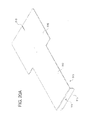
- FIG. 34 is a left side view of the shipping container of FIG. 1 , illustrating the top compartment in the expanded position relative to the bottom compartment, and the cover of the material unloading assembly in an open position.
- FIG. 35 is a top perspective view of the top wall of the top compartment of the shipping container of FIG. 1 , shown removed from the top compartment and illustrating the opening in the top wall and the lip of the material loading assembly extending from the top wall and which is configured to be securely engaged by the cover of the material loading assembly.
- FIG. 36 is a top perspective view of the cover of the material loading assembly of the shipping container of FIG. 1 , shown removed from the top compartment and illustrating in phantom the channel of the cover which is configured to receive the lip of the of the material loading assembly attached to the top compartment for secure engagement by the cover.
- FIG. 37 is an enlarged fragmentary perspective view of the locking assembly of the material loading assembly of the shipping container of FIG. 1 , shown in the closed position.
- FIG. 38 is an enlarged perspective view of one of the nesting or stacking guides of the shipping container of FIG. 1 , shown removed from the top compartment and illustrating the bag end holders defined by the nesting or stacking guides.
- FIG. 39 is an enlarged fragmentary side view of a portion of the top compartment of a first shipping container of FIG. 1 and a portion of the pallet and lower compartment of a second shipping container of FIG. 1 shown stacked on the top compartment of the first shipping container.
- FIG. 40 is an enlarged fragmentary perspective view of a portion of the top compartment of a first shipping container of FIG. 1 and a pallet of a second shipping container of FIG. 1 shown stacked on the top compartment of the first shipping container.
- FIG. 41 is a perspective view of the shipping container of FIG. 1 and a bag positioned over the stacking guides, and with the cover of the material loading assembly removed for ease of illustration.
- FIG. 42 is a perspective view of the shipping container of FIG. 1 and a bag positioned with its ends extending through the stacking guides, and with the cover of the material loading assembly removed for ease of illustration.
- FIG. 43 is a perspective view of the shipping container of FIG. 1 and a bag holder of one embodiment of the present disclosure which is configured to hold a roll of bags.
- FIG. 44 is a perspective view of the shipping container of FIG. 1 and the bag holder of FIG. 43 , and illustrating how the bag holder of FIG. 41 holds one of the bags over the shipping container during the material loading process, and with the cover of the material loading assembly removed for ease of illustration.
- FIG. 45 is a perspective view of the shipping container of FIG. 1 and another embodiment of a bag holder of the present disclosure.
- FIG. 46 is a perspective view of the shipping container of FIG. 1 and the bag holder of FIG. 45 , and illustrating how the bag holder of FIG. 43 holds one of the bags over the shipping container during the material loading process, and with the cover of the material loading assembly removed for ease of illustration.
- FIGS. 1 to 40 illustrate one example embodiment of the bulk material shipping container of the present disclosure.
- This shipping container which is generally indicated by numeral 50 , has an expanded position for holding materials during shipping and a retracted position for efficient shipping when the container is not holding materials or when the container is holding a smaller amount of materials. More specifically, FIG. 2 illustrates the shipping container 50 in the retracted position, and FIGS. 1 , 3 , 4 , 5 , 34 illustrate the shipping container 50 in the expanded position. It should thus be appreciated that in the retracted position (as shown in FIG. 2 ), the shipping container 50 can be used for efficient transport as further described below, and that this provides substantial savings in shipping cost and energy use.
- this illustrated embodiment of the shipping container 50 includes: (a) a pallet 100 (as partially shown in FIGS. 1 , 2 , 3 , 4 , 5 , 7 , 8 , 9 , and 9 F, and as best shown in FIGS. 10 , 10 A, 11 , 12 , 13 , 14 , 15 , 16 , 17 , 17 A, 18 , 18 A, 19 , 19 A, 24 , 25 , and 26 ) configured for supporting the container 50 and to facilitate movement and of the container 50 as well as the stacking of multiple containers; (b) a bottom compartment 200 (as best shown in FIGS.
- a pallet 100 as partially shown in FIGS. 1 , 2 , 3 , 4 , 5 , 7 , 8 , 9 , and 9 F, and as best shown in FIGS. 10 , 10 A, 11 , 12 , 13 , 14 , 15 , 16 , 17 , 17 A, 18 , 18 A, 19 , 19 A, 24 , 25 , and
- top compartment 300 (as best shown in FIGS. 1 , 2 , 3 , 4 , 5 , 6 , 8 , and 34 ) mounted on the bottom compartment 200 and configured to hold materials; (d) a plurality of top compartment support assemblies 400 (as partially shown in FIGS. 1 , 2 , 3 , 4 , 5 , and 8 , and as best shown in FIGS.
- a material unloading assembly 500 (as partially shown in FIGS. 3 , 4 , 7 , 8 , 9 E, and 9 F and as best shown in FIGS.
- the container includes a front side or face, a back side or face opposite the front side, a right side or face, and a left side or face as further discussed below.
- the pallet 100 is approximately 56 inches (142.24 centimeters) by approximately 44 inches (111.76 centimeters) by approximately 6 inches (15.24 centimeters);
- the bottom compartment 200 is approximately 56 inches (142.24 centimeters) by approximately 44 inches (111.76 centimeters) by approximately 27 inches (68.58 centimeters);
- the top compartment 300 is approximately 56 inches (142.24 centimeters) by approximately 44 inches (111.76 centimeters) by approximately 27 inches (68.58 centimeters).
- the container When the container is in the retracted position, the container is approximately 56 inches (142.24 centimeters) by approximately 44 inches (111.76 centimeters) by approximately 35 inches (88.90 centimeters). When the container is in the expanded position, the container is approximately 56 inches (142.24 centimeters) by approximately 44 inches (111.76 centimeters) by approximately 62 inches (157.48 centimeters). However, it should be appreciated that the container and the components thereof may be other suitable sizes.
- This embodiment of the shipping container of the present disclosure is configured to directly hold materials or to receive and hold a large plastic bag which holds the materials in the interior areas defined by bottom and top compartments.
- the bag : (a) is approximately 60 inches (15.40 centimeters) by approximately 55 inches (139.70 centimeters) by approximately 110 inches (279.40 centimeters); (b) has a flat bottom with no bottom seal and hermetic side seals; (c) is FDA compliant; (d) has an approximately 2 millimeter thickness; (e) is clear; and (f) is made from a low density recyclable polyethylene plastic.
- the bag is also or alternatively bio-degradable. It should be appreciated that each of the bags is thus suited to hold one load of materials.
- the plastic bag may be of any suitable size, configuration, and material, provided that it fits inside of the top and bottom compartments of the container and that the bottom of the bag is able to be readily opened for unloading of the materials. It should be appreciated that the bag will be appropriately folded so that when the bag is placed above and partially in the container for filling the bag (and the container) with the materials, that the bag will properly unfold and be suitably seated in the top and bottom compartments of the container. The filling and un-filling of the bag is further discussed below.
- the bottom compartment 200 includes: (a) a lower exterior bottom wall or panel 202 defining a material release opening or chute 204 ; (b) an upper interior bottom wall 210 defined by four attached downwardly angled sections or chute ramps 212 , 214 , 216 , and 218 ; (c) four wedge shaped interior bottom wall supports or gussets 222 , 224 , 226 , and 228 ; (d) spaced apart first and second or front and back exterior walls 232 and 236 ; and (e) spaced apart third and fourth or left and right exterior side walls 234 and 238 .
- the four sections 212 , 214 , 216 , and 218 of the upper interior bottom wall 210 , the front and back exterior walls 232 and 236 , and the exterior side walls 234 and 238 define a bottom compartment material holding area or cavity which extends downwardly toward and to the material release opening or chute 204 .
- the lower exterior bottom wall 202 , the upper interior bottom wall 210 , the interior bottom wall supports 222 , 224 , 226 , and 228 , the front and back exterior walls 232 and 236 , and the exterior side walls 234 and 238 are all made of stainless steel or galvanized steel to: (a) facilitate attachment or connection of these parts by welding and/or suitable fasteners; (b) provide structural strength and rigidity; (c) facilitate ease of cleaning; (d) facilitate ease of repair; (e) prevent rusting; (f) minimize overall weight of the container; and (g) prevent contamination.
- one or more of these components can be made from other suitable materials and that these components can be attached or connected in other suitable manners.
- the exterior bottom wall 202 of the bottom compartment 200 is suitably attached to the pallet 100 of the container 50 by suitable fasteners; however, it should be appreciated that the exterior bottom wall can be attached in other suitable manners.
- the lower exterior bottom wall 202 includes: (a) a rectangular substantially flat base 206 which defines the centrally located rectangular material release opening or chute 204 ; and (b) an upwardly extending lip 208 extending upwardly from each of outer edges of the base 206 .
- This material release opening or chute 204 enables materials in the top and bottom compartments (or in a bag therein) to flow out of bottom compartment 200 when the chute door or gate 510 of the material unloading assembly for the opening or chute 204 (and the bag therein) is opened as further discussed below.
- the opening 204 in this illustrated embodiment is approximately 8 inches (20.32 centimeters) by approximately 11 inches (27.94 centimeters), although it should be appreciated that the opening may be of other suitable sizes. This size of the opening relative to the size of the bottom and top compartments maximizes the rate of unloading of the material from the top and bottom compartments (or in a bag therein) without sacrificing structure or strength of the bottom compartment.
- the interior bottom wall supports 222 , 224 , 226 , and 228 are attached in spaced apart locations to the top of the base 206 by fasteners, although they can also or alternatively be attached by welding.
- Each of the interior bottom wall supports or gussets 222 , 224 , 226 , and 228 are of a wedge shape such that they are configured to be engaged by and support a respective one of the downwardly angled sections 212 , 214 , 216 , and 218 of the upper interior bottom wall 210 .
- the gusset 222 is wider than the other gussets 224 , 226 , and 228 in this illustrated embodiment to distribute the weight of the materials supported by gusset 222 to the pallet 100 at further spaced apart locations which are not directly over the gate 510 of the material unloading assembly 500 (which is further described below).
- the upper interior bottom wall 210 and specifically the four downwardly angled sections 212 , 214 , 216 , and 218 are respectively attached to the interior bottom wall supports or gussets 222 , 224 , 226 , and 228 by welding, although they can also or alternatively be attached by fasteners.
- the interior bottom wall supports or gussets 222 and 226 are some what shorter (as best seen in FIGS.
- the four downwardly angled sections 212 , 214 , 216 , and 218 each have a lower edge such that when such sections are attached, such sections form an opening 211 adjacent to and substantially aligned with the opening 204 of the base wall 206 .
- the lower edges of the four downwardly angled sections 212 , 214 , 216 , and 218 extend downwardly approximately adjacent to the material release opening or chute 204 of the base 206 of the bottom compartment.
- the lower edges of one or more of these four downwardly angled sections are each configured to be supported by the pallet adjacent to the top shelf of the pallet. In other words, this construction enables the central area of the pallet to provided support for part of the weight of the materials held in the top and bottom compartments.
- the upper interior bottom wall 210 , and specifically upper portions of the four downwardly angled sections 212 , 214 , 216 , and 218 are also respectively attached to and supported by the exterior walls 232 , 234 , 236 , and 238 . It should thus be appreciated that the upper interior bottom wall 210 of the bottom compartment 200 is supported at multiple locations including multiple points of support by the various different portions of the pallet 100 .
- the sections 212 , 214 , 216 , and 218 of the upper interior bottom wall 210 are supported: (a) at their top ends by the exterior walls 232 , 234 , 236 , and 238 of the bottom compartment 200 ; (b) centrally by interior bottom wall supports or gussets 222 , 224 , 226 , and 228 ; (c) by attachment to each other; and (d) by the central portion of the pallet 100 .
- the exterior walls 232 , 234 , 236 , and 238 of the bottom compartment 200 also each includes a skirt that extends downwardly along a respective side of the pallet 100 . Suitable fasteners such as screws are used to attach each skirt to the respective side of the pallet 100 to support these exterior walls. Thus, it should be appreciated that this attachment to the side walls of the pallet 100 provides another set of support points for the bottom compartment 200 . It should thus be appreciated that the upper interior bottom wall 210 is suitably angled and supported to hold the materials without deforming and to facilitate unloading of the bulk material from the material holding area of the bottom compartment.
- Each of the exterior walls 232 , 234 , 236 , and 238 of the bottom compartment 210 include a rectangular panel and two L-shaped corner sections attached to opposite ends of the panel.
- Each L-shaped corner section of each panel of each exterior wall is configured to mate with the L-shaped corner of an adjacent exterior wall as generally shown in FIGS. 27A , 27 B, and 27 C.
- These L-shaped corner sections of each of the exterior side wall (a) are preferably connected by welding; (b) add structural rigidity to the bottom compartment; and (c) in conjunction with the top compartment support assemblies 400 provide support the support of the top compartment in the expanded position as further described below. More specifically, as illustrated in FIGS.
- exterior side wall 232 includes panel 252 and corner 262 which includes corner sections 262 a and 262 b
- exterior side wall 234 includes panel 254 and corner 264 which includes corner sections 264 a and 264 b .
- Corner sections 264 a is mated with and attached to corner section 262 a
- corner section 264 b is mated with and attached to corner section 262 b to form this corner of the bottom compartment 200 . It should be appreciated that each corner of the bottom compartment is configured in a similar manner; however, it should be appreciated that one or more of the corners can be differently configured.
- each of the exterior walls 232 , 234 , 236 , and 238 of the bottom compartment 210 also includes a top edge which is curled or bent over to provide extra strength to the bottom compartment and to minimize interference with movement of the top compartment 300 relative to the bottom compartment 200 .
- the top compartment 300 of the container 50 includes an exterior top wall 302 , spaced apart exterior front and back side walls 312 and 316 , spaced apart exterior side walls 316 and 318 , and exterior wall support brackets 322 , 324 , 326 , and 328 respectively attached to the exterior side walls 312 , 314 , 316 , and 318 .
- the exterior top wall 302 , exterior side walls 312 , 314 , 316 , and 318 , and exterior wall support brackets 322 , 324 , 326 , and 328 are also all made of stainless steel or galvanized steel to: (a) facilitate attachment or connection of these parts by welding and/or suitable fasteners; (b) provide structural strength and rigidity; (c) facilitate ease of cleaning; (d) facilitate ease of repair; (e) prevent rusting; (f) minimize overall weight of the container; and (g) prevent contamination.
- one or more of these components can be made from other suitable materials and attached or connected in any suitable manner.
- the upper interior base wall 306 and the exterior walls 312 , 314 , 316 , and 318 define a top compartment material holding area or cavity which extends downwardly to the bottom compartment material holding area or cavity.
- the exterior top wall 302 includes a rectangular substantially flat base 306 which defines the centrally located rectangular material receipt or loading opening or chute 304 .
- This material receipt or loading opening or chute 304 enables materials to flow into the top and bottom compartments when the cover of the material loading assembly is opened as further discussed below.
- the opening 304 in this illustrated embodiment is 18 inches (45.72 centimeters) by 18 inches (45.72 centimeters), although it should be appreciated that the opening may be of other suitable sizes. This size opening relative to this size bottom and top compartments maximizes the rate of loading of the material into the top and bottom compartments without sacrificing structure or strength of the top compartment 300 .
- the upper interior base wall 306 is suitably attached to the upper portions of the exterior walls 312 , 314 , 316 , and 318 by welding.
- the exterior wall support brackets 322 , 324 , 326 , and 328 are respectively attached to the exterior side walls 312 , 314 , 316 , and 318 by welding, although they can be attached by rivets or other suitable fasteners. It should be appreciated that for embodiments of the container which will employ a bag, it is preferable to maximize the amount of welding for connecting or attaching components to reduce possible spots or points for snagging or cutting the bag. It should also be appreciated that for a container that will not employ a bag, more rivets or other fasteners can be employed.
- each of the exterior walls 312 , 314 , 316 , and 318 include a rectangular panel and two L-shaped corner sections attached to opposite ends of the panel.
- Each L-shaped corner section of each panel of each exterior wall is configured to mate with the L-shaped corner of the adjacent exterior wall similar to the bottom compartment.
- These L-shaped corner sections of each of the exterior side wall of the top compartment are preferably connected by welding and add structural rigidity to the top compartment.
- the top compartment can include one or more interior walls. These interior walls in certain embodiment are used to protect the exterior walls, and to add further structural rigidly to the top compartment.
- the pallet 100 of this illustrated embodiment of the shipping container 50 of the present disclosure is specifically configured to take in account that various different lifting and moving vehicles or equipment may be used to lift and move the container 50 : (a) when the container is manufactured; (b) when the container is transported to a material loading facility; (c) when the container is at a material loading facility; (d) when the container is moved and positioned in a transport vehicle at the material loading facility after loading materials in the container; (e) when the container is removed from a transport vehicle at a material unloading facility; (f) when the container is at an unloading facility; and (g) when the container is moved and positioned in a transport vehicle at the material unloading facility after unloading the materials from the container.
- these facilities will typically have either a conventional pallet jack and/or a conventional fork lift.
- One widely commercially used conventional pallet jack has spaced apart non-movable tines or forks, where each fork is approximately 7.75 inches (19.69 centimeters) wide and the space between the tines is approximately 8.50 inches (21.59 centimeters).
- One widely commercially used conventional fork lift has adjustably spaced apart tines or forks, where each fork is approximately 5 inches (12.70 centimeters) wide, and the space between that tines is adjustable from approximately 4 inches (10.16 centimeters) to approximately 24 inches (60.96 centimeters).
- the container 50 and specifically the pallet 100 of the container 50 is configured to account for the use of such fork lifts which can: (a) lift the containers off of the ground; (b) move the containers; (c) stack the containers on top of each other; and (d) un-stack stacked containers from each other.
- the container 50 and specifically the pallet 100 of the container 50 is also configured to account for the use of such pallet jacks which can: (a) lift the containers off of the ground; and (b) move the containers, but can not stack or un-stack stacked containers.
- the pallet 100 of this illustrated embodiment of the container 50 of the present disclosure includes: (a) a rectangular body 102 having an upper surface 104 , a lower surface 106 , a front edge 112 , a back edge 116 , and opposite side edges 114 and 118 ; and (b) a plurality of legs 122 , 124 , 126 , and 128 extending downwardly from the body 102 .
- the legs 122 and 126 each respectively extend the entire width of the body 102 of the pallet 100 in this illustrated embodiment.
- the legs 122 and 126 do not need to extend the entire width of the body and that each of these legs can be separated into multiple legs.
- the legs or islands 124 and 128 extend downwardly from the central portions of the side ends of the body 102 .
- the body and the legs of the pallet are all formed from one piece of a suitable wood to: (a) provide structural strength and rigidity; and (b) minimize overall weight of the container.
- the wood pallet is one piece of wood which is suitably formed by suitable cutting, milling and/or routing processes.
- the pallet can be made from multiple components which are suitably attached and that one or more of these components can be made from other suitably strong materials such as composite or fiber glass materials. It should also be appreciated that different parts of the pallet may be made from different materials. For instance, the shelves may be made from a plastic, composite or fiber glass inlay part.
- the pallet 100 includes or defines: (a) a first set of aligned fork lift tine receiving channels 132 a and 136 a in the legs 122 and 126 , respectively; (b) a second set of aligned fork lift tine receiving channels 132 b and 136 b in the legs 122 and 126 , respectively; (c) a first pallet jack tine receiving channel 140 extending from side to side; and (d) a second pallet jack tine receiving channel 142 extending from side to side.
- the first set of fork lift tine receiving channels 132 a and 136 a and the second set of fork lift tine receiving channels 132 b and 136 b are positioned and spaced apart such that when the forks or tines of a fork lift are inserted into these channels of the pallet 100 of the container 50 which is stacked on top of another container, the tines or forks do not engage the material loading assembly on the top compartment of the lower container or the extension assembly on the top compartment of the lower container. It should thus be appreciated that the pallet 100 is configured to enable a fork lift to move these containers when one container is stacked on another container without damaging the lower container, and particularly the cover or the extension assembly.
- the first pallet jack tine receiving channel 140 and the second pallet jack tine receiving channel 142 are positioned and spaced apart such that when the forks or tines of a pallet jack are inserted into these channels defined by the pallet 100 of the container 50 , they can lift and move the container. It should be appreciated that a typical pallet jack does not operate like a fork lift so that the pallet jack will only be used when the container is on the floor or ground and not with stacked containers. Therefore, the tines or forks of a pallet jack will not be in a position to engage the material loading assembly on the top compartment of the lower container of stacked containers or the extension assembly on the top compartment of the lower container of stacked containers.
- first set of aligned fork lift tine receiving channels 132 a and 136 a and the second set of aligned fork lift tine receiving channels 132 b and 136 b are not configured to receive the forks or tines of a pallet jack because they are spaced apart further then the tines on a conventional pallet jack (as described above). Specifically, they are spaced apart approximately 34 inches (86.36 centimeters) in this illustrated embodiment.
- a fork lift with adjustable forks or tines can be inserted into the first pallet jack tine receiving channels 140 and 142 to lift and move the container 50 .
- the pallet 50 and the channels 140 and 142 are also configured to take this into account, and specifically to account for this situation when the forks or tines of a fork lift are inserted into these channels 140 and 142 of the pallet 100 of a container stacked on another container, these tines or forks do not engage the material loading assembly on the top compartment of the lower container or the extension assembly on the top compartment of the lower container.
- the legs 124 and 128 of the pallet 100 are also configured to direct the tines or forks of the pallet jack through the channels 140 and 142 if they are inserted at an angle with respect to these channels.
- leg 124 includes four angled tine directing surfaces 154 a , 154 b , 154 c , and 154 d
- leg 128 includes four angled tine directing surfaces 158 a , 158 b , 158 c , and 158 d .
- the legs 124 and 128 do not block the fork lift tine receiving channels 132 a and 136 a or the fork lift tine receiving channels 132 b and 136 b.
- the pallet can include indicator which direct a user on how to insert the tines of a fork lift into the pallet jack receiving channels 140 and 142 . It should also be appreciated, that although not shown, the pallet can include hinged or pivoting flaps in the ends of the pallet jack receiving channels 140 and 142 to further direct a user on how to insert the tines of a fork lift into the pallet jack receiving channels 140 and 142 .
- the shape of the legs of the pallet which rest on the ground, and particularly the flat surfaces of the pallet, prevent the build-up of contaminants on the pallet.
- the bottom of the pallet does not include a series of cavities in which contaminants such as mud or dirt can build up. Therefore, the pallet provides a less contaminable bulk material container while still being relatively strong and light weight.
- the body 102 of the pallet 100 also functions: (a) to support the upper interior bottom wall of the bottom compartment 200 ; and (b) to support the material unloading assembly 500 . More specifically, the body 102 of the pallet 100 defines multi-level shelves including a first or bottom shelf 150 and a second or top shelf 160 , and an opening or chute 170 .
- the first or bottom shelf 150 includes front shoulder 152 , left side shoulder 154 , and right side shoulder 158 . These shoulders 152 , 154 , and 158 are sized and configured to support a bottom portion of each of the guide rails and the door or gate of the material unloading assembly which is further described below.
- the door or gate includes a closure member or portion and the handle member or portion (as further discussed below).
- the shoulders 152 , 154 , and 158 support the guide rails (attached to the bottom compartment as described below) which in turn support the side edges of the closure member as well as the handle portion of the chute door or gate of the material unloading assembly.
- the shoulders 152 , 154 , and 158 are positioned at the same level to co-act to support the chute door or gate of the material unloading assembly such that the chute door or gate moves or slides relative to the bottom shelf 150 from a closed position to an open position for respectively closing and opening the chute 202 in the exterior bottom wall of the bottom compartment 100 as well as the opening or chute 170 in the pallet 100 as further discussed below.
- the second or top shelf of the pallet 100 includes left side shoulder 164 , rear shoulder 166 , and right side shoulder 168 which are configured at the same level to co-act to also support a top portion of each of the guide rails and the door or gate of the material unloading assembly which is further described below. It should also be appreciated that this configuration enables the pallet to support the bottom compartment and the material unloading assembly and specifically the chute door or gate. This support reduces the amount of weight placed on the gate from the materials held in the top and bottom compartments (or the bag therein).
- the container 50 and in particular the material unloading assembly 500 includes a plurality of guide rails 163 , 165 , 167 , 169 , and 171 .
- Guide rail 163 is secured to the exterior bottom wall 206 and is configured and positioned to be supported by the front portions of shoulders 154 and 164 .
- Guide rail 165 is secured to the exterior bottom wall 206 and is configured and positioned to be supported by the central and rear portions of the shoulders 154 and 164 .
- Guide rail 167 is secured to the exterior bottom wall 206 and is configured and positioned to be supported by the rear shoulders 156 and 166 .
- Guide rail 169 is secured to the exterior bottom wall 206 and is configured and positioned to be supported by the central and rear portions of shoulders 158 and 168 .
- Guide rail 171 is secured to the exterior bottom wall 206 and is configured and positioned to be supported by the front portions of the shoulders 158 and 168 . It should be appreciated that FIGS. 10A , 14 , 15 , and 16 illustrate these guide rails 163 , 165 , 167 , 169 , and 171 detached from or without the exterior bottom wall 206 and in the positions where they rest on and are supported by these shoulders of the pallet 100 . It should also be appreciated that these guide rails function in multiple ways.
- the guide rails 163 , 165 , 167 , 169 , and 171 support and guide the movement of closure portion and the handle portion of the chute door or gate 510 of the material unloading assembly 500 .
- the gate slides or moves on or above these guide rails 163 , 165 , 167 , 169 , and 171 , and these guide rails prevent the downward movement of the chute door or gate and also prevent loose materials being held in the top and bottom compartments from accumulating on or adjacent to the chute door or gate or the shoulders.
- the guide rails 165 , 167 , and 169 also rest on the shoulders to provide additional support for the bottom compartment.
- the material unloading assembly 500 of the container 50 is supported by both bottom wall 206 of the bottom compartment 200 and the body 102 of the pallet 100 under and adjacent to the opening or chute 204 in the bottom compartment 200 and above the opening or chute 170 in the pallet 100 .
- the material unloading assembly 500 includes a chute door or gate 510 slidably positioned on the guide rails 163 , 165 , 167 , 169 , and 171 , and partially supported by the shoulders— 152 , 154 , and 158 defined by the body 102 of the pallet 100 as discussed above.
- the gate 510 includes a handle member or portion 512 and a closure member or portion 516 extending from the handle member or portion 512 .
- the gate 510 is movable or slidable from a closed position as shown in FIGS. 9C , 9 D, 9 E, 9 F, 14 , 17 , and 17 A to a plurality of different partially open positions (such as the partially open position shown in FIGS.
- the body 102 of the pallet 100 defines a plurality of stopping walls that prevent the gate 510 from moving too far outwardly and also keeps the handle portion 512 of the gate 510 relatively close to the pallet 100 .
- the gate and the guide rails are made of stainless steel or galvanized steel to: (a) provide structural strength and rigidity; (b) facilitate ease of cleaning; (c) facilitate ease of repair; (d) prevent rusting; (e) minimize overall weight of the container; and (f) prevent contamination.
- the gate and the guide rails can be made from other suitable materials.
- the material unloading assembly 500 further includes a knife 520 attached to the bottom surface of the gate 510 .
- the knife 520 includes a biasing member in the form of a leaf spring 522 having an attachment end 524 attached to the bottom surface of the gate 510 and a fin shaped blade 530 attached to the top side of the opposite or free end 526 of leaf spring 522 .
- the fin shaped blade 530 includes: (a) an attachment base 532 attached to the top of the free end 526 of the leaf spring 522 ; and (b) a cutting member 534 attached to and extending from the attachment base 532 .
- the cutting member 534 includes an accurate shaped cutting edge 536 and back edge 538 opposite the cutting edge 536 .
- the leaf spring 522 biases the blade 530 upwardly such that the blade 530 is biased upwardly and the cutting member 534 and extends through a vertically extending slot 518 (see FIGS. 20A and 20B ) in the closure portion 516 of the gate 510 toward a fully expanded position.
- the knife is made of stainless steel or galvanized steel to: (a) facilitate attachment or connection of these parts by welding and/or suitable fasteners; (b) facilitate ease of cleaning; (c) facilitate ease of repair; (d) prevent rusting; (e) minimize overall weight of the container; and (f) prevent contamination.
- the knife can be made from other suitable materials.
- the leaf spring is made of stainless steel or galvanized steel; however, it should be appreciated that in alternative embodiments, the leaf spring can be made from other suitable materials and in other configurations.
- the knife 520 (including the leaf spring 522 and the blade 530 ) moves as the gate 510 moves, and specifically is configured to move from a retracted position as shown in FIGS. 14 , 17 , 17 A, and 20 D to a plurality of different extended positions such as the partially extended position shown in FIGS. 15 , 18 , and 18 A and to a fully extended position shown in FIGS. 16 , 19 , and 19 A.
- the gate 510 is configured to be opened by an unloader such that pulling the handle portion 512 of the gate (and particularly the handle 513 ) from the closed position to an open position, causes the blade 530 of the cutting member 534 of the knife 520 to extend through the slot 518 and to engage the bottom of the bag (not shown) in the container 50 which holds the material, and to cut a hole in the bottom of the bag to release the material in the bag.
- the cutting member 534 of the blade 530 rests below the guide rail 167 as shown in FIGS. 9C , 9 D, 17 , and 17 A.
- the cutting member 534 of the blade 530 is adjacent to the front section 212 of the interior bottom wall 210 as shown in FIGS. 19 and 19A . It should further be appreciated that as the gate 510 is moved from the fully open position to the closed position, the knife 520 (including the leaf spring 522 and the blade 530 ) moves with the gate 510 from the fully extended position to a partially retracted position to a fully retracted position.
- the back edge 538 of the cutting member 534 is configured such that when the back edge 538 of the cutting member 534 contacts the bottom of the guide rail 167 , the entire blade 520 and the free end 526 of the leaf spring 522 is forced downwardly against the upward bias of the leaf spring 522 and back into the retracted position as shown in FIGS. 9C , 9 D, 17 , and 17 a . It should also be appreciated that the knife 520 does not interfere with the opening of the gate in the embodiments where a bag is not employed to hold the materials in the container.
- the material unloading assembly 500 also includes a locking assembly 550 configured to enable a user to lock the gate 510 , and specifically the handle portion 512 of the gate 510 to the stopping wall 182 of the pallet 510 to prevent the handle portion 512 and the gate 510 from being accidentally opened at undesired points in time such as: (a) during loading of the container 50 ; (b) during transit of the container 50 ; or (c) at any other point in time prior to an unloader opening the gate 510 . More specifically, as best seen in FIGS.
- the handle portion 512 of the gate 510 includes a downwardly extending handle 513 which is configured to be gripped by a user to open and close the gate 510 .
- the downwardly extending handle 513 defines a centrally located opening 514 (as best shown in FIG. 20A ).
- the material unloading assembly 500 also includes a stopping plate 560 attached to the outside surface of the stopping wall 182 .
- the stopping plate 560 includes an opening 561 aligned with the centrally located opening 514 of the handle 513 of the handle portion 512 of the gate 510 .
- the stopping wall 182 also includes a hole which is larger than the hole 561 in the stopping plate 560 and is configured to receive a locking pin 590 .
- the material unloading assembly 500 further includes a locking pin 590 configured to be inserted through: (a) the centrally located opening 514 of the handle 513 of the handle portion 512 of the gate 510 ; (b) the opening 561 in the stopping plate 560 ; and (c) an opening 183 in the stopping wall 182 , when the gate 510 is in the closed position.
- This locking pin 590 engages the rear surface of the stopping plate 560 to prevent unwanted opening of the gate 510 .
- the locking pin 590 When the user desires to open the gate 510 , the user activates the locking pin 590 and fully or partially removes the locking pin 590 from the stopping wall 182 and the stopping plate 560 . It should be appreciated that as shown in the various figures, the locking pin 590 can be left in the handle 513 of the gate 510 . It should also be appreciated that the locking pin can be placed in a different hole in the handle of the gate 510 . It should further be appreciated, that although not shown, the material unloading assembly can further include one or more guides for holding the locking pin 590 level or otherwise in position for easy re-insertion when the gate 510 is in a fully open or partially open position. It should be appreciated that the locking pin can be commercially obtained from MCMASTER-CARR, and that any other suitable locking pin may be employed.
- the chute can be closed or partially closed. It should also be appreciated that by pushing the handle back toward the closed position, the chute can be closed or partially closed. It should also be appreciated that placing the handle in a partially open or partially closed positioned enables the user to control the rate of emptying the materials from the container 50 .
- each top compartment support assembly 400 a , 400 b , 400 c , and 400 d is identical; however, it should be appreciated that two or more of these support assemblies may be different.
- Support assembly 400 a is discussed herein as an example.
- Support assembly 400 a includes a support pin 410 a configured to be inserted through a pin receipt or pin receipt hole 450 a (at least shown in FIGS. 8 and 27B ) in the corner of the bottom compartment 200 and into a tubular support pin receiver or sleeve 412 a of the support assembly 400 a which is suitably attached (such as by welding) to the inside of the corner of the bottom compartment 200 as best illustrated in FIG. 31 .
- the configuration and size of the support pin receiver can vary in accordance with the present disclosure.
- the support pin receiver can be in the form of a flat plate (not shown) attached to the inside of the corner of the bottom compartment.
- the support assembly 400 a further includes a support pin holder 430 a and a tether 460 a attaching the support pin 420 a to the support pin holder 430 a .
- the support pin holder 430 a and the tether 460 a are employed to prevent the support pin 410 a from being lost and to hold the support pin 410 a out of the way of the bottom compartment 200 when the support pin 410 a is not in use, and that in alternative embodiments, the shipping container of the present disclosure does not employ the support pin holders or the tethers. It should also be appreciated that FIGS.
- the support pin holder 430 a includes an L-shaped body having a mounting member 432 a attached to the corner of the top compartment 300 and a pin holder 434 a connected to the mounting member 432 a .
- the pin holder 464 a defines a first hole 436 a for attachment of the one end of the tether 430 a and a second hole 438 a for removably holding the support pin 410 a when the support pin 410 a is not in use.
- This support pin holder 430 a is made from stainless steel or galvanized steel, and welded to the corner of the top compartment 300 .
- the pin holder 434 a could be made from other suitable materials, could be suitably attached to the top compartment in other suitable manners or locations and could be alternatively configured.
- the pin holder is made of stainless steel or galvanized steel to: (a) facilitate attachment or connection of this part by welding and/or suitable fasteners to the top compartment; (b) provide structural strength and rigidity; (c) facilitate ease of cleaning; (d) facilitate ease of repair; (e) prevent rusting; (f) minimize overall weight of the container; and (g) prevent contamination.
- the pin holder can be made from other suitable materials and attached or connected to the top compartment in other suitable manners
- the tether 460 a includes two end loops 462 a and 464 a . End loop 462 a is attached to the support pin holder 430 a and end loop 464 b is attached to the support pin 410 a .
- the tether 460 a may be any suitable length and made from any suitable material such as steel or a high strength plastic.
- the support pin 410 a in the illustrated embodiment includes a handle 413 a , a tubular body 414 a attached to the handle 412 a , and a locking mechanism 416 a extending through the handle 413 a and tubular body 414 a .
- the locking mechanism 416 a includes a release button 418 a in and extending from the handle 413 a , an actuation shaft (not shown) connected to the release button 418 a , and a plurality of locking balls 422 a and 422 b extending transversely from the from the tubular body 414 a adjacent to the end of the tubular body 414 a opposite the handle 413 a .
- the locking mechanism 416 a is configured such that the locking balls 422 a and 422 b are normally biased by a spring (not shown) toward the outwardly extending locked position as shown in FIG. 31 , and such that when the release button 418 a is pressed, the locking balls 422 a and 422 b are allowed to recede inwardly into the tubular member 414 a and specifically into cavities (not shown) in the actuation shaft 420 a to enable the support pin 410 a to be removed.
- the locking balls 422 a and 422 b are configured to engage the inner surface of the tubular support pin receiver 412 a of the support assembly 400 a to prevent the support pin 410 a in the locked position from being easily removed or removed without actuation of the locking mechanism 416 a and specifically the release button 418 a .
- Pins of this type are readily commercially available such as from MCMASTER-CARR. It should be appreciated that other suitable support pins may be employed with the container in accordance with the present disclosure.
- the container 50 includes an extension assembly 700 which enables a user or loader to move the top compartment from the retracted position to the expanded position to enable insertion of these support pins as further described below.
- the extension assembly 700 of the container 50 includes a first set of aligned fork lift tine receiving loops or lifting brackets 702 and 704 and a second set of aligned forklift tine receiving loops or lifting brackets 706 and 708 .
- Each of the lift tine receiving loops or lifting brackets 702 , 704 , 706 , and 708 are identical in this illustrated embodiment, but it should be appreciated that these components can be different.
- FIG. 1 , 4 , 5 , 6 , 8 , and 33 the extension assembly 700 of the container 50 includes a first set of aligned fork lift tine receiving loops or lifting brackets 702 and 704 and a second set of aligned forklift tine receiving loops or lifting brackets 706 and 708 .
- Each of the lift tine receiving loops or lifting brackets 702 , 704 , 706 , and 708 are identical in this illustrated embodiment, but it should be appreciated that these components can be different.
- FIG. 33 illustrate example fork lift tine receiving loop or lifting bracket 702 , which includes a crossbar 720 a , end bars 722 a and 724 a attached to the opposite ends of the crossbar 720 a and mounting bars 726 a and 728 a respectively attached to the opposite ends of the end bars 722 a and 724 a .
- these loops or lifting brackets are made of stainless steel or galvanized steel and the mounting bars are each suitably welded to the top wall 302 of the top compartment 300 .
- the loops or lifting brackets are suitably aligned to form two slots configured to receive forklift forks or tines.
- loops enable a loader operating a fork lift to insert the forks of the forklift through the loops and to lift the top compartment from the retracted position to the expanded position.
- These aligned slots enable a forklift to lift the top compartment of the container from either the front or back. It should be appreciated that the outside surfaces of the container can include suitable markings to indicate to the loader the appropriate expanded position of the top compartment.
- these loop are all made of stainless steel or galvanized steel to: (a) facilitate attachment or connection of these parts by welding and/or suitable fasteners; (b) provide structural strength and rigidity; (c) facilitate ease of cleaning; (d) facilitate ease of repair; (e) prevent rusting; (f) minimize overall weight of the container; and (g) prevent contamination.
- one or more of these loops can be made from other suitable materials and that these components can be attached or connected in other suitable manners.
- the locking assemblies described above can then be employed to support and lock the top compartment in the expanded position and to prevent the top compartment from moving back into the retracted position. More specifically, when a user such as a loader of the shipping container 50 desires to move the top compartment from the retracted position to the expanded position, the user uses a fork lift or other lifting apparatus to engage the extension assembly 700 to lift the top compartment 300 such that the bottom corners of the top compartment 300 are above the pin receipt holes in the four corners of the bottom compartment 200 . The user then sequentially takes each support pin out of the respective pin holder, presses the button on the support pin and inserts the support pin in the respective pin receipt hole.
- a single loader can move the top compartment into the expanded position by lifting the top compartment (using a fork lift); (b) the single loader can engage the support pins of the top compartment supporting assemblies to lock the top compartment in the expanded position; and (c) that prior to unloading the materials, a single unloader can disengage the support pins from the bottom compartment to un-lock the top compartment from the expanded position and release the top compartment from the expanded position, which enables the top compartment to slowly move to the retracted position as the materials empties from the top and bottom compartments. This also prevents the top compartment from rapidly dropping if the support pins are released when no materials are in the compartments. It should further be appreciated that enabling a single person to perform this operation provide a significant advantage in terms of time and cost over certain prior known bulk material shipping containers.
- the material loading assembly 600 is generally attached to the top compartment 300 and generally includes: (a) an upwardly extending lip 602 attached to and extending from the top wall 302 of the top compartment 300 ; (b) a cover 610 configured to securely engage the upwardly extending lip 602 and pivotally attached to the top wall 302 of the top compartment 300 by a plurality of hinges 630 , 632 , and 634 ; (c) a lock assembly 650 including a first portion 652 attached to the top wall 302 of the top compartment 300 and a second portion or lid latch 654 pivotally attached to the cover 610 ; (d) and a gasket (not shown) mounted in the cover 610 to seal out contaminants.
- the cover 610 defines a channel 612 configured to receive the lip 602 .
- the gasket is mounted in the channel 612 to facilitate the seal between the cover 610 and the lip 602 .
- additional material is preferably welded to the illustrated sections of the lip 602 to form a continuous lip.
- the locking assembly 650 includes a suitable lock (not shown) which is used to lock the cover 610 in the closed position, and specifically to lock the second portion or lid latch 654 attached to the cover to the first portion 652 attached to the top wall 302 of the top compartment 300 . It should be appreciated that any suitable lock may be employed and that alternative configurations for the locking assembly may be employed in accordance with the present disclosure.
- these components are all made of stainless steel or galvanized steel to: (a) facilitate attachment or connection of these parts by welding and/or suitable fasteners; (b) provide structural strength and rigidity; (c) facilitate ease of cleaning; (d) facilitate ease of repair; (e) prevent rusting; (f) minimize overall weight of the container; and (g) prevent contamination.
- one or more of these components can be made from other suitable materials and that these components can be attached or connected in other suitable manners.
- the shape of the cover may vary in accordance with the present disclosure.
- the container 50 includes a plurality of nesting or stacking or guides 800 a , 800 b, 800 c , and 800 d which are configured to facilitate secure stacking of the containers of the present disclosure as well as stacking of other known bulk material containers.
- each of the stacking guides 800 a , 800 b , 800 c , and 800 d is identical; however, it should be appreciated that two or more of these stacking guides may be different.
- the stacking guides assist in positioning one container of the present disclosure on top of another container of the present disclosure.
- stacking guide 800 a is discussed herein as an example stacking guide.
- stacking guide 800 a include mounting walls 802 a and 804 a configured to be attached to the corner of the top compartment 300 and guide wall 812 a and 814 a respectively attached to and extend from the mounting walls 802 a and 804 a .
- the guide wall 812 a and 814 a each respectively define bag holding slots 820 a and 822 a . These slots are configured to receive and hold a top section of a bag during the filling process to secure the bag in the desired position as the loader fills the bag and the container with materials to the desired height (as generally illustrated in FIG. 42 and as further described below).
- the stacking guides are all made of stainless steel to: (a) facilitate attachment or connection of these parts to the top compartment by welding and/or suitable fasteners; (b) provide structural strength and rigidity; (c) facilitate ease of cleaning; (d) facilitate ease of repair; (e) prevent rusting; (f) minimize overall weight of the container; and (g) prevent contamination.
- one or more of these stacking guides can be made from other suitable materials and that these components can be attached or connected in other suitable manners.
- the container 50 and the nesting or stacking guides 800 a , 800 b , 800 c , and 800 d of the container 50 are configured to receive or be stacked with known bulk material containers such as the known bulk material container described in the background section of this document. It should be appreciated that as shown in FIGS. 39 and 40 , the container of the present disclosure is configured such that a fork lift can be employed to place one container on top of another container and to lift one container from another container without damaging the material loading assembly attached to the top compartment of the lower container, and without damaging the extension assembly attached to the top compartment of the lower container.
- FIG. 41 the container 50 is illustrated with a bag 850 shown draped over the stacking guides 800 a , 800 b , 800 c , and 800 d .
- the stacking guides 800 a , 800 b , 800 c , and 800 d act as holders and guides for the bag 850 during the loading process.
- the center of the bag 852 is positioned over the opening in the top compartment and under a loading tube 890 .
- the cover of the material loading assembly has been removed for ease of illustration.
- FIG. 42 the container 50 is illustrated with a bag 850 shown with each end respectively extending through the stacking guides 800 a , 800 b , 800 c , and 800 d .
- the stacking guides 800 a , 800 b , 800 c , and 800 d act as holders and guides for the bag 850 during the loading process.
- the center of the bag 852 is positioned over the opening in the top compartment and under a loading tube 890 . It should be appreciated that the cover of the material loading assembly has been removed for ease of illustration.
- FIGS. 43 and 44 one example embodiment of a bag holder of the present disclosure is generally illustrated and indicated by numeral 1000 .
- the bag holder 1000 is configured to hold a supply roll of bags 900 and to sequentially provide each of the bags from the supply roll 900 for positioning over the shipping container during the material loading processes.
- the first bag 860 of the supply roll of bags 900 is shown draped over the stacking guides 800 a , 800 b , 800 c , and 800 d .
- the stacking guides 800 a , 800 b , 800 c , and 800 d act as holders and guides for the bag 860 during the loading process.
- the center 862 of the bag 860 is positioned over the opening in the top compartment and under a loading tube 890 .
- the bag holder 1000 in this embodiment includes a pallet jack 1010 , a bag guide 1020 connected to and supported by the pallet jack 1010 , and a supply roll support holder 1030 connected to and supported by the pallet jack 1010 .
- the bag guide 1020 is sized and configured to hold a bag over the container 50 during the loading process and to prevent the bag from engaging the various components of the container and thus prevent the bag from catching on or ripping from contact with the components of the container.
- the bag holder 1000 holds the bag 860 over the container 50 with the center of the bag 862 positioned over the opening in the top compartment and under a loading tube 890 . It should be appreciated with respect to FIG. 44 that the cover of the material loading assembly has been removed for ease of illustration.
- FIGS. 45 and 46 another example embodiment of a bag holder of the present disclosure is generally illustrated and indicated by numeral 1100 .
- the bag holder 1100 is similar to the bag holder 1000 in that it is configured to hold a bag over the shipping container 50 during the material loading process. However, unlike bag holder 1000 , bag holder 1100 is not configured to hold a roll of bags and does not include a supply roll support holder.
- the bag holder 1100 in this embodiment includes a pallet jack 1010 and a bag guide 1120 connected to and supported by the pallet jack 1010 .
- the bag guide 1120 is sized and configured to hold a bag over the container 50 during the loading process and to prevent the bag from engaging the various components of the container and thus prevent the bag from catching on or ripping from contact with the components of the container.
- the bag holder 1000 holds the bag 870 over the container 50 with the center of the bag 872 positioned over the opening in the top compartment and under a loading tube 890 . It should be appreciated with respect to FIG. 46 that the cover of the material loading assembly has been removed for ease of illustration.
- the pallet jack 1010 is configured to be positioned underneath the container 50 , and specifically that the forks are positioned in the pallet jack tine receiving channels defined by the pallet. It should also be appreciated that the bag holder could alternatively include a fork lift instead of a pallet jack and that in such embodiments, the forks are preferably positioned in the fork lift tine receiving channels defined by the pallet. It should further be appreciated that in alternative embodiments, the bag guides and supply roll support holder can be alternatively supported and positionable. It should be appreciated that the bag guide and supply roll support holder are made from any suitable materials.
- the shipping container includes (a) a pallet; (b) a bottom compartment mounted on the pallet; (c) a top compartment securely mounted on the bottom compartment; (d) a material unloading assembly supported by bottom compartment and the pallet; and (e) a material loading assembly attached to the top compartment.
- the top compartment is fixed such as by welding to the bottom compartment.
- This embodiment does not include the plurality of top compartment supporting assemblies or the extension assembly attached to the top compartment.
- the bulk material shipping container of the present disclosure can be used with a bag or without a bag.
- the shipping container includes: (a) a pallet; (b) a single compartment mounted on the pallet; (c) a material unloading assembly supported by the bottom compartment and the pallet; and (d) a material loading assembly attached to the top compartment. Since this embodiment includes a single compartment, this embodiment does not need to include the plurality of compartment supporting assemblies or the extension assembly attached to the top compartment. In this embodiment, the bulk material shipping container of the present disclosure can also be used with a bag or without a bag.
- suitable instructional marking or labels may be placed on or attached to the container of the present disclosure to instruct the users on how to load, unload, move, retract, and/or expand the container.
- suitable reflective tape strips can be attached to the container.
- the container of the present disclosure can be suitably coated such as by painting with a clear or colored protective coating. It should be appreciated that such coating may include a UV protective agent.
- one or more sections of the container may be reinforced with a suitable plating to provide additional protection and strength.
- the attachment of the various components of the container can be preformed in any suitable way such as by welding (including but not limited to laser welding) and by suitable fasteners (such as but not limited to rivets).
Abstract
Description
Claims (33)
Priority Applications (13)
| Application Number | Priority Date | Filing Date | Title |
|---|---|---|---|
| US12/914,075 US8616370B2 (en) | 2010-10-28 | 2010-10-28 | Bulk material shipping container |
| US13/249,688 US8887914B2 (en) | 2010-10-28 | 2011-09-30 | Bulk material shipping container |
| PCT/US2011/056728 WO2012058059A1 (en) | 2010-10-28 | 2011-10-18 | Bulk material shipping container |
| EP11836876.0A EP2632813A4 (en) | 2010-10-28 | 2011-10-18 | Bulk material shipping container |
| US14/516,292 US9617065B2 (en) | 2010-10-28 | 2014-10-16 | Bulk material shipping container |
| US15/471,896 US9988182B2 (en) | 2010-10-28 | 2017-03-28 | Bulk material shipping container |
| US15/631,737 US9758993B1 (en) | 2010-10-28 | 2017-06-23 | Bulk material shipping container |
| US15/632,696 US9783338B1 (en) | 2010-10-28 | 2017-06-26 | Bulk material shipping container |
| US15/634,383 US9796504B1 (en) | 2010-10-28 | 2017-06-27 | Bulk material shipping container |
| US15/637,325 US9828135B2 (en) | 2010-10-28 | 2017-06-29 | Bulk material shipping container |
| US15/973,796 US10189599B2 (en) | 2010-10-28 | 2018-05-08 | Bulk material shipping container |
| US16/217,940 US10486854B2 (en) | 2010-10-28 | 2018-12-12 | Bulk material shipping container |
| US16/665,488 US11059622B2 (en) | 2010-10-28 | 2019-10-28 | Bulk material shipping container |
Applications Claiming Priority (1)
| Application Number | Priority Date | Filing Date | Title |
|---|---|---|---|
| US12/914,075 US8616370B2 (en) | 2010-10-28 | 2010-10-28 | Bulk material shipping container |
Related Child Applications (1)
| Application Number | Title | Priority Date | Filing Date |
|---|---|---|---|
| US13/249,688 Continuation-In-Part US8887914B2 (en) | 2010-10-28 | 2011-09-30 | Bulk material shipping container |
Publications (2)
| Publication Number | Publication Date |
|---|---|
| US20120103848A1 US20120103848A1 (en) | 2012-05-03 |
| US8616370B2 true US8616370B2 (en) | 2013-12-31 |
Family
ID=45995460
Family Applications (1)
| Application Number | Title | Priority Date | Filing Date |
|---|---|---|---|
| US12/914,075 Active 2031-12-11 US8616370B2 (en) | 2010-10-28 | 2010-10-28 | Bulk material shipping container |
Country Status (1)
| Country | Link |
|---|---|
| US (1) | US8616370B2 (en) |
Cited By (58)
| Publication number | Priority date | Publication date | Assignee | Title |
|---|---|---|---|---|
| US20130206616A1 (en) * | 2012-02-13 | 2013-08-15 | Phillip John Allen | Cleanroom box |
| US20140166647A1 (en) * | 2012-02-10 | 2014-06-19 | Sancan, Inc. | Container to deliver bulk granular material |
| USRE45713E1 (en) | 2012-11-02 | 2015-10-06 | Oren Technologies, Llc | Proppant vessel base |
| US9162603B2 (en) | 2011-12-21 | 2015-10-20 | Oren Technologies, Llc | Methods of storing and moving proppant at location adjacent rail line |
| USRE45788E1 (en) | 2012-11-02 | 2015-11-03 | Oren Technologies, Llc | Proppant vessel |
| US9296518B2 (en) | 2011-12-21 | 2016-03-29 | Oren Technologies, Llc | Proppant storage vessel and assembly thereof |
| US9340353B2 (en) | 2012-09-27 | 2016-05-17 | Oren Technologies, Llc | Methods and systems to transfer proppant for fracking with reduced risk of production and release of silica dust at a well site |
| US9394102B2 (en) | 2012-07-23 | 2016-07-19 | Oren Technologies, Llc | Proppant discharge system and a container for use in such a proppant discharge system |
| US9421899B2 (en) | 2014-02-07 | 2016-08-23 | Oren Technologies, Llc | Trailer-mounted proppant delivery system |
| US9446801B1 (en) | 2013-04-01 | 2016-09-20 | Oren Technologies, Llc | Trailer assembly for transport of containers of proppant material |
| US9624030B2 (en) | 2014-06-13 | 2017-04-18 | Oren Technologies, Llc | Cradle for proppant container having tapered box guides |
| USRE46381E1 (en) | 2012-11-02 | 2017-05-02 | Oren Technologies, Llc | Proppant vessel base |
| US9650216B2 (en) | 2013-01-22 | 2017-05-16 | Arrows Up, Llc | Bulk material shipping container unloader |
| US9670752B2 (en) | 2014-09-15 | 2017-06-06 | Oren Technologies, Llc | System and method for delivering proppant to a blender |
| US9676554B2 (en) | 2014-09-15 | 2017-06-13 | Oren Technologies, Llc | System and method for delivering proppant to a blender |
| US20170203875A1 (en) * | 2014-05-30 | 2017-07-20 | Softbox Systems Limited | Transport and storage system |
| US9718610B2 (en) | 2012-07-23 | 2017-08-01 | Oren Technologies, Llc | Proppant discharge system having a container and the process for providing proppant to a well site |
| US9758082B2 (en) | 2013-04-12 | 2017-09-12 | Proppant Express Solutions, Llc | Intermodal storage and transportation container |
| USRE46576E1 (en) | 2013-05-17 | 2017-10-24 | Oren Technologies, Llc | Trailer for proppant containers |
| USRE46590E1 (en) | 2013-05-17 | 2017-10-31 | Oren Technologies, Llc | Train car for proppant containers |
| US9809381B2 (en) | 2012-07-23 | 2017-11-07 | Oren Technologies, Llc | Apparatus for the transport and storage of proppant |
| USRE46613E1 (en) | 2012-11-02 | 2017-11-28 | Oren Technologies, Llc | Proppant vessel |
| US9845210B2 (en) | 2016-01-06 | 2017-12-19 | Oren Technologies, Llc | Conveyor with integrated dust collector system |
| USRE46645E1 (en) | 2013-04-05 | 2017-12-26 | Oren Technologies, Llc | Trailer for proppant containers |
| USRE47162E1 (en) | 2012-11-02 | 2018-12-18 | Oren Technologies, Llc | Proppant vessel |
| US10167138B2 (en) | 2012-02-10 | 2019-01-01 | Can Do Logistics Llc | Method for delivery of proppant to a frac site |
| USD847489S1 (en) | 2012-09-24 | 2019-05-07 | Sandbox Logistics, Llc | Proppant container |
| US10518828B2 (en) | 2016-06-03 | 2019-12-31 | Oren Technologies, Llc | Trailer assembly for transport of containers of proppant material |
| US10604333B2 (en) | 2016-04-28 | 2020-03-31 | Bradford Company | Container having at least one lockable crossbar assembly movable along tracks |
| US10604334B2 (en) | 2016-04-28 | 2020-03-31 | Bradford Company | Container having multiple layers of dunnage, at least one layer having at least one lockable crossbar assembly |
| US10618744B2 (en) | 2016-09-07 | 2020-04-14 | Proppant Express Solutions, Llc | Box support frame for use with T-belt conveyor |
| US10676239B2 (en) | 2016-06-30 | 2020-06-09 | Sandbox Logistics, Llc | Bulk material shipping container |
| US10759610B1 (en) | 2019-05-03 | 2020-09-01 | Sandbox Logistics, Llc | Bulk material conveyor |
| US10919693B2 (en) | 2016-07-21 | 2021-02-16 | Halliburton Energy Services, Inc. | Bulk material handling system for reduced dust, noise, and emissions |
| US10926940B2 (en) | 2018-11-20 | 2021-02-23 | Sandbox Enterprises, Llc | Bulk material shipping container |
| US10994954B2 (en) | 2016-06-30 | 2021-05-04 | Sandbox Enterprises, Llc | Bulk material shipping container unloader |
| US11047717B2 (en) | 2015-12-22 | 2021-06-29 | Halliburton Energy Services, Inc. | System and method for determining slurry sand concentration and continuous calibration of metering mechanisms for transferring same |
| US11066259B2 (en) | 2016-08-24 | 2021-07-20 | Halliburton Energy Services, Inc. | Dust control systems for bulk material containers |
| US11173826B2 (en) | 2019-06-12 | 2021-11-16 | Sandbox Enterprises, Llc | Bulk material shipping container trailer |
| US11174071B2 (en) | 2016-04-28 | 2021-11-16 | Bradford Company | Container having multiple layers of lockable crossbar assemblies for keeping products inside container |
| US11186318B2 (en) | 2016-12-02 | 2021-11-30 | Halliburton Energy Services, Inc. | Transportation trailer with space frame |
| US11186454B2 (en) | 2016-08-24 | 2021-11-30 | Halliburton Energy Services, Inc. | Dust control systems for discharge of bulk material |
| US11186452B2 (en) | 2015-11-25 | 2021-11-30 | Halliburton Energy Services, Inc. | Sequencing bulk material containers for continuous material usage |
| US11186431B2 (en) | 2016-07-28 | 2021-11-30 | Halliburton Energy Services, Inc. | Modular bulk material container |
| US11192077B2 (en) | 2015-07-22 | 2021-12-07 | Halliburton Energy Services, Inc. | Blender unit with integrated container support frame |
| US11192731B2 (en) | 2015-05-07 | 2021-12-07 | Halliburton Energy Services, Inc. | Container bulk material delivery system |
| US11192074B2 (en) | 2016-03-15 | 2021-12-07 | Halliburton Energy Services, Inc. | Mulling device and method for treating bulk material released from portable containers |
| US11254483B2 (en) | 2016-04-28 | 2022-02-22 | Bradford Company | Container having at least one lockable crossbar assembly movable along tracks |
| US11273421B2 (en) | 2016-03-24 | 2022-03-15 | Halliburton Energy Services, Inc. | Fluid management system for producing treatment fluid using containerized fluid additives |
| US11311849B2 (en) | 2016-03-31 | 2022-04-26 | Halliburton Energy Services, Inc. | Loading and unloading of bulk material containers for on site blending |
| US11338260B2 (en) | 2016-08-15 | 2022-05-24 | Halliburton Energy Services, Inc. | Vacuum particulate recovery systems for bulk material containers |
| US11395998B2 (en) | 2017-12-05 | 2022-07-26 | Halliburton Energy Services, Inc. | Loading and unloading of material containers |
| US11498037B2 (en) | 2016-05-24 | 2022-11-15 | Halliburton Energy Services, Inc. | Containerized system for mixing dry additives with bulk material |
| US11661235B2 (en) | 2018-10-15 | 2023-05-30 | Sandbox Enterprises, Llc | Bulk material shipping container top wall assembly and bulk material shipping container having a top wall assembly |
| US11691831B2 (en) | 2019-01-22 | 2023-07-04 | 543077 Alberta Ltd. | Portable conveyor system including pivotable and extendable feed conveyors for feeding particulate material into an elevating assembly |
| US11814242B2 (en) | 2015-07-22 | 2023-11-14 | Halliburton Energy Services, Inc. | Mobile support structure for bulk material containers |
| US11873160B1 (en) | 2014-07-24 | 2024-01-16 | Sandbox Enterprises, Llc | Systems and methods for remotely controlling proppant discharge system |
| US11880804B1 (en) | 2020-04-29 | 2024-01-23 | Prop Sense Canada Ltd. | System and method for automated inventory, transport, management, and storage control in hydraulic fracturing operations |
Families Citing this family (6)
| Publication number | Priority date | Publication date | Assignee | Title |
|---|---|---|---|---|
| WO2013167154A1 (en) * | 2012-05-09 | 2013-11-14 | Schoeller Arca Systems Gmbh | Large-load carrier with hopper-like insert element |
| DE102017107351A1 (en) | 2017-04-05 | 2018-10-11 | Mts Maschinentechnik Schrode Ag | soil recycler |
| US20180312332A1 (en) * | 2017-04-28 | 2018-11-01 | Fred Loeber | Reusable, Collapsible Containers |
| USD873524S1 (en) * | 2017-07-21 | 2020-01-21 | The United States Of America As Represented By The Secretary Of The Army | Collapsible pallet consolidator |
| USD894520S1 (en) * | 2018-09-05 | 2020-08-25 | The Alternative Pallet Company Limited | Pallet |
| US10969189B1 (en) * | 2020-01-30 | 2021-04-06 | Workshops for Warriors | Weapon maintenance system |
Citations (83)
| Publication number | Priority date | Publication date | Assignee | Title |
|---|---|---|---|---|
| US572468A (en) * | 1896-12-01 | Hoisting and dumping platform | ||
| US3318473A (en) * | 1964-08-11 | 1967-05-09 | Benjamin D Jones | Portable dispensing bin |
| US3797727A (en) | 1972-03-10 | 1974-03-19 | Caterpillar Tractor Co | Collapsible container and assembly method therefor |
| US3904105A (en) | 1973-10-18 | 1975-09-09 | Olinkraft Inc | Bulk material container |
| US3955703A (en) | 1973-05-14 | 1976-05-11 | Zebarth Ralph S | Collapsible shipping container |
| US3999290A (en) | 1976-03-15 | 1976-12-28 | Wood Jess W | Safety knife |
| US4019634A (en) | 1975-03-19 | 1977-04-26 | Pierre Edmond Michel Bonnot | Collapsible shipping container |
| US4019635A (en) | 1974-11-14 | 1977-04-26 | Akzo N.V. | Pallet-container for transporting bulk material |
| EP0016977A1 (en) | 1979-04-05 | 1980-10-15 | Rhein - Conti Kunststoff-Technik GmbH | Pallet-container |
| GB2066220A (en) | 1979-12-06 | 1981-07-08 | Williamson K E | Improvements in or relating to the dispensing of free-flowing material |
| US4280640A (en) | 1978-06-22 | 1981-07-28 | Pennsylvania Pacific Corporation | Integral double-wall container |
| NL8105283A (en) | 1981-11-23 | 1983-06-16 | Estel Hoogovens Bv | Sack opening and emptying system - cuts along slot between table halves then swung into vertical position |
| US4397406A (en) * | 1981-06-26 | 1983-08-09 | Willamette Industries, Inc. | Knocked-down drum-like fiberboard container for bulk material with funnel-like dispensing bottom |
| US4448296A (en) | 1981-09-08 | 1984-05-15 | Buckhorn Material Handling Group Inc. | Live guide system for gravity conveyors |
| US4466541A (en) | 1982-04-26 | 1984-08-21 | Buckhorn Material Handling Group Inc. | Molded container with integral hinge |
| US4470518A (en) | 1981-11-03 | 1984-09-11 | Buckhorn Material Handling Group Inc. | Security box having a sliding lid |
| US4485910A (en) | 1982-04-15 | 1984-12-04 | Buckhorn Material Handling Group Inc. | Container handling system |
| US4572368A (en) | 1985-07-18 | 1986-02-25 | Buckhorn Material Handling Group, Inc. | Tote box |
| US4573577A (en) | 1980-02-08 | 1986-03-04 | Buckhorn Material Handling Group Inc. | Stackable container |
| US4574962A (en) | 1983-04-25 | 1986-03-11 | Buckhorn Material Handling Group, Inc. | Storage and retrieval system |
| US4600103A (en) | 1984-03-21 | 1986-07-15 | Buckhorn Material Handling Group, Inc. | Symmetrical bakery basket |
| USD285219S (en) | 1983-09-19 | 1986-08-19 | Buckhorn Material Handling Group Inc. | Document box |
| US4620644A (en) | 1981-03-27 | 1986-11-04 | Buckhorn Material Handling Group Inc. | Tote box with lid container |
| US4643310A (en) | 1984-09-20 | 1987-02-17 | Buckhorn Material Handling Group, Inc. | One hundred eighty degree stack and nest bakery tray with bails |
| US4648200A (en) | 1984-08-20 | 1987-03-10 | Buckhorn Material Handling Group Inc. | Crustacean trap |
| US4648199A (en) | 1984-08-20 | 1987-03-10 | Buckhorn Material Handling Group Inc. | Crustacean trap |
| USD289788S (en) | 1984-08-21 | 1987-05-12 | Buckhorn Material Handling Group Inc. | Crustacean trap |
| USD290778S (en) | 1984-05-29 | 1987-07-07 | Buckhorn Material Handling Group Inc. | Bakery basket |
| US4688675A (en) | 1985-02-27 | 1987-08-25 | Buckhorn Material Handling Group, Inc. | Nesting box with reduced lid flares |
| USD292718S (en) | 1983-09-19 | 1987-11-10 | Buckhorn Material Handling Group Inc. | Document box |
| US4724976A (en) | 1987-01-12 | 1988-02-16 | Lee Alfredo A | Collapsible container |
| US4756420A (en) | 1987-03-19 | 1988-07-12 | Buckhorn, Inc. | Multi size nesting containers with anti jamming |
| US4760922A (en) | 1987-06-30 | 1988-08-02 | International Paper Company Incorporated | Combination pallet and collapsible container mounted thereon |
| US4779751A (en) | 1987-04-06 | 1988-10-25 | Thomas Munroe | Knock-down containers, container fastening system and elements thereof |
| US4804082A (en) | 1987-04-08 | 1989-02-14 | Buckhorn, Inc. | Security box having sliding closure |
| US4809851A (en) | 1987-04-03 | 1989-03-07 | World Container Corporation | Collapsible container |
| US4832200A (en) | 1987-10-06 | 1989-05-23 | Buckhorn Material Handling Group, Inc. | Stacking arrangement for containers |
| USRE32966E (en) | 1985-07-18 | 1989-06-27 | Buckhorn Material Handling Group, Inc. | Tote box |
| USD304120S (en) | 1987-01-07 | 1989-10-17 | Buckhorn Material Handling Group, Inc. | Lidded storage bin |
| US4890740A (en) | 1988-10-25 | 1990-01-02 | Buckhorn, Inc. | Snap together picking container |
| US4917255A (en) | 1989-02-24 | 1990-04-17 | J.I.T. Corporation | Collapsible container |
| USD307718S (en) | 1986-04-17 | 1990-05-08 | Buckhorn, Inc. | Interfitting container |
| US4936458A (en) | 1988-11-21 | 1990-06-26 | Buckhorn, Inc. | Bakery tray with blend stacking |
| US4948186A (en) * | 1989-04-19 | 1990-08-14 | Carolina Slings Co., Inc. | Lifting means for a paper roll |
| US4960207A (en) | 1988-11-21 | 1990-10-02 | Buckhorn, Inc. | Bakery tray with blind stacking and unstacking |
| USRE33384E (en) | 1985-02-27 | 1990-10-16 | Buckhorn, Inc. | Nesting box with reduced lid flares |
| US4966310A (en) | 1988-12-01 | 1990-10-30 | Hawkins Gerald P | Collapsible storage container and method for storing matter |
| US4974737A (en) | 1990-03-21 | 1990-12-04 | Buckhorn, Inc. | Extension ring |
| US5094356A (en) | 1990-11-13 | 1992-03-10 | Buckhorn Material Handling Group, Inc. | Knock down bulk container |
| US5232120A (en) | 1991-06-04 | 1993-08-03 | 21St Century Containers, Ltd. | Container for bulk liquids and solids |
| US5277014A (en) | 1992-09-14 | 1994-01-11 | Abr Corporation | Bag discharge station |
| US5330069A (en) | 1993-04-12 | 1994-07-19 | Buckhorn Material Handling Group, Inc. | Bi-fold lid for container |
| US5439113A (en) | 1993-06-07 | 1995-08-08 | Macroplastics, Inc. | Bulk container |
| US5524750A (en) | 1995-08-04 | 1996-06-11 | Buckhorn Material Handling Group, Inc. | Card holder for container |
| US5667090A (en) | 1995-10-06 | 1997-09-16 | General Motors Corporation | Returnable shipping container |
| US5673791A (en) | 1994-10-04 | 1997-10-07 | Buckhorn Material Handling Group, Inc. | Container and lid for container |
| US5722550A (en) | 1996-06-06 | 1998-03-03 | Buckhorn Material Handling Group, Inc. | Container having reusable base and disposable over sleeve |
| US5788121A (en) | 1994-11-18 | 1998-08-04 | Kabushiki Kaisha Hosokawa Yoko | Bag for bag-in-box and bag-in-box |
| US5845799A (en) | 1994-05-18 | 1998-12-08 | Buckhorn Material Handling Group, Inc. | Dispensing gate for knock down bulk box |
| US5878903A (en) | 1996-08-28 | 1999-03-09 | Ung; Lu-Hsiung | Extensible and extractable cargo container |
| US6010022A (en) | 1994-05-18 | 2000-01-04 | Buckhorn, Inc. | Dispensing box for flowable material |
| US6112929A (en) | 1998-12-31 | 2000-09-05 | Ota; Hideyuki | Collapsible cargo container and method or use |
| US6253948B1 (en) | 1999-01-29 | 2001-07-03 | Buckhorn, Inc. | Nestable container with expendable closure panel covering access opening in container wall |
| WO2001076960A1 (en) | 2000-04-07 | 2001-10-18 | Arca Xytec Systems, Inc. | Collapsible container with closed, multi-paneled side walls |
| US20020023994A1 (en) * | 2000-08-31 | 2002-02-28 | De Shann Barbara A. | Computer navigator armrest device |
| US6491343B2 (en) * | 2000-01-14 | 2002-12-10 | Combi Corporation | Booster seat |
| US20030024971A1 (en) | 1999-07-13 | 2003-02-06 | Jones Robert J. | Collapsible bulk material container |
| US20040222222A1 (en) | 2003-05-05 | 2004-11-11 | John Parnall | Bulk shipping container having adjustable height, collapsible walls |
| US20040232146A1 (en) | 2003-05-20 | 2004-11-25 | Kessler John E. | Collapsible shipping container |
| US7032765B2 (en) | 2002-02-22 | 2006-04-25 | Buckhorn, Inc. | Container with over center corner latches |
| US7100791B2 (en) | 2002-05-17 | 2006-09-05 | Buckhorn, Inc. | Hinged lid trash can for curbside refuse pickup |
| US20060266747A1 (en) | 2005-05-24 | 2006-11-30 | Stolzman Michael D | Bulk container |
| WO2007081556A2 (en) | 2006-01-05 | 2007-07-19 | Bellehumeur Alexander R | Collapsible storage container and panel |
| US20070210080A1 (en) * | 2006-03-08 | 2007-09-13 | Hooper Robert C | Multi-Use Intermodal Container |
| US20070241104A1 (en) | 2006-04-03 | 2007-10-18 | Huizingh Jan A | Storage and transport container with telescopic side walls |
| US20070278223A1 (en) | 2006-06-05 | 2007-12-06 | Paul Ficker | Locking collapsible container |
| US20080169285A1 (en) | 2007-01-16 | 2008-07-17 | Nick Marazita | Collapsible container |
| USD575062S1 (en) * | 2006-11-15 | 2008-08-19 | Aaron Wolf | Storage container cover |
| US7431173B2 (en) * | 2001-11-30 | 2008-10-07 | Almar Packaging International Inc. | Intermediate bulk container with pallet and pole supported upper member |
| US20090000527A1 (en) | 2007-06-26 | 2009-01-01 | Paul Ficker | Three piece welded plastic pallet |
| US7475796B2 (en) * | 2005-05-17 | 2009-01-13 | Snyder Industries, Inc. | Industrial hopper with support |
| US7543539B2 (en) | 2005-04-01 | 2009-06-09 | Buckhorn, Inc. | Pallet having divided areas supporting separately removable portions of a pallet load |
| US7762281B2 (en) * | 2006-08-02 | 2010-07-27 | Bushnell Illinois Tanks Co. | Storage and dispensing bin |
-
2010
- 2010-10-28 US US12/914,075 patent/US8616370B2/en active Active
Patent Citations (90)
| Publication number | Priority date | Publication date | Assignee | Title |
|---|---|---|---|---|
| US572468A (en) * | 1896-12-01 | Hoisting and dumping platform | ||
| US3318473A (en) * | 1964-08-11 | 1967-05-09 | Benjamin D Jones | Portable dispensing bin |
| US3797727A (en) | 1972-03-10 | 1974-03-19 | Caterpillar Tractor Co | Collapsible container and assembly method therefor |
| US3955703A (en) | 1973-05-14 | 1976-05-11 | Zebarth Ralph S | Collapsible shipping container |
| US3904105A (en) | 1973-10-18 | 1975-09-09 | Olinkraft Inc | Bulk material container |
| US4019635A (en) | 1974-11-14 | 1977-04-26 | Akzo N.V. | Pallet-container for transporting bulk material |
| US4019634A (en) | 1975-03-19 | 1977-04-26 | Pierre Edmond Michel Bonnot | Collapsible shipping container |
| US3999290A (en) | 1976-03-15 | 1976-12-28 | Wood Jess W | Safety knife |
| US4280640A (en) | 1978-06-22 | 1981-07-28 | Pennsylvania Pacific Corporation | Integral double-wall container |
| EP0016977A1 (en) | 1979-04-05 | 1980-10-15 | Rhein - Conti Kunststoff-Technik GmbH | Pallet-container |
| GB2066220A (en) | 1979-12-06 | 1981-07-08 | Williamson K E | Improvements in or relating to the dispensing of free-flowing material |
| US4573577A (en) | 1980-02-08 | 1986-03-04 | Buckhorn Material Handling Group Inc. | Stackable container |
| US4620644A (en) | 1981-03-27 | 1986-11-04 | Buckhorn Material Handling Group Inc. | Tote box with lid container |
| US4397406A (en) * | 1981-06-26 | 1983-08-09 | Willamette Industries, Inc. | Knocked-down drum-like fiberboard container for bulk material with funnel-like dispensing bottom |
| US4448296A (en) | 1981-09-08 | 1984-05-15 | Buckhorn Material Handling Group Inc. | Live guide system for gravity conveyors |
| US4470518A (en) | 1981-11-03 | 1984-09-11 | Buckhorn Material Handling Group Inc. | Security box having a sliding lid |
| NL8105283A (en) | 1981-11-23 | 1983-06-16 | Estel Hoogovens Bv | Sack opening and emptying system - cuts along slot between table halves then swung into vertical position |
| US4485910A (en) | 1982-04-15 | 1984-12-04 | Buckhorn Material Handling Group Inc. | Container handling system |
| US4466541A (en) | 1982-04-26 | 1984-08-21 | Buckhorn Material Handling Group Inc. | Molded container with integral hinge |
| US4574962A (en) | 1983-04-25 | 1986-03-11 | Buckhorn Material Handling Group, Inc. | Storage and retrieval system |
| USD292718S (en) | 1983-09-19 | 1987-11-10 | Buckhorn Material Handling Group Inc. | Document box |
| USD285219S (en) | 1983-09-19 | 1986-08-19 | Buckhorn Material Handling Group Inc. | Document box |
| US4600103A (en) | 1984-03-21 | 1986-07-15 | Buckhorn Material Handling Group, Inc. | Symmetrical bakery basket |
| USD290778S (en) | 1984-05-29 | 1987-07-07 | Buckhorn Material Handling Group Inc. | Bakery basket |
| US4648200A (en) | 1984-08-20 | 1987-03-10 | Buckhorn Material Handling Group Inc. | Crustacean trap |
| US4648199A (en) | 1984-08-20 | 1987-03-10 | Buckhorn Material Handling Group Inc. | Crustacean trap |
| USD289788S (en) | 1984-08-21 | 1987-05-12 | Buckhorn Material Handling Group Inc. | Crustacean trap |
| US4643310A (en) | 1984-09-20 | 1987-02-17 | Buckhorn Material Handling Group, Inc. | One hundred eighty degree stack and nest bakery tray with bails |
| US4688675A (en) | 1985-02-27 | 1987-08-25 | Buckhorn Material Handling Group, Inc. | Nesting box with reduced lid flares |
| USRE33384E (en) | 1985-02-27 | 1990-10-16 | Buckhorn, Inc. | Nesting box with reduced lid flares |
| USRE32966E (en) | 1985-07-18 | 1989-06-27 | Buckhorn Material Handling Group, Inc. | Tote box |
| US4572368A (en) | 1985-07-18 | 1986-02-25 | Buckhorn Material Handling Group, Inc. | Tote box |
| USD307718S (en) | 1986-04-17 | 1990-05-08 | Buckhorn, Inc. | Interfitting container |
| USD304120S (en) | 1987-01-07 | 1989-10-17 | Buckhorn Material Handling Group, Inc. | Lidded storage bin |
| US4724976A (en) | 1987-01-12 | 1988-02-16 | Lee Alfredo A | Collapsible container |
| US4756420A (en) | 1987-03-19 | 1988-07-12 | Buckhorn, Inc. | Multi size nesting containers with anti jamming |
| US4809851A (en) | 1987-04-03 | 1989-03-07 | World Container Corporation | Collapsible container |
| US4779751A (en) | 1987-04-06 | 1988-10-25 | Thomas Munroe | Knock-down containers, container fastening system and elements thereof |
| US4804082A (en) | 1987-04-08 | 1989-02-14 | Buckhorn, Inc. | Security box having sliding closure |
| US4760922A (en) | 1987-06-30 | 1988-08-02 | International Paper Company Incorporated | Combination pallet and collapsible container mounted thereon |
| US4832200A (en) | 1987-10-06 | 1989-05-23 | Buckhorn Material Handling Group, Inc. | Stacking arrangement for containers |
| US4890740A (en) | 1988-10-25 | 1990-01-02 | Buckhorn, Inc. | Snap together picking container |
| US4960207A (en) | 1988-11-21 | 1990-10-02 | Buckhorn, Inc. | Bakery tray with blind stacking and unstacking |
| US4936458A (en) | 1988-11-21 | 1990-06-26 | Buckhorn, Inc. | Bakery tray with blend stacking |
| US4966310A (en) | 1988-12-01 | 1990-10-30 | Hawkins Gerald P | Collapsible storage container and method for storing matter |
| US4917255A (en) | 1989-02-24 | 1990-04-17 | J.I.T. Corporation | Collapsible container |
| US4948186A (en) * | 1989-04-19 | 1990-08-14 | Carolina Slings Co., Inc. | Lifting means for a paper roll |
| US4974737A (en) | 1990-03-21 | 1990-12-04 | Buckhorn, Inc. | Extension ring |
| US5094356A (en) | 1990-11-13 | 1992-03-10 | Buckhorn Material Handling Group, Inc. | Knock down bulk container |
| US5232120A (en) | 1991-06-04 | 1993-08-03 | 21St Century Containers, Ltd. | Container for bulk liquids and solids |
| US5373961A (en) | 1991-06-04 | 1994-12-20 | 21St Century Containers, Ltd. | Transportable, self-supporting container |
| US5277014A (en) | 1992-09-14 | 1994-01-11 | Abr Corporation | Bag discharge station |
| US5330069A (en) | 1993-04-12 | 1994-07-19 | Buckhorn Material Handling Group, Inc. | Bi-fold lid for container |
| US5439113B1 (en) | 1993-06-07 | 2000-04-25 | Macroplastics Inc | Bulk container |
| US5439113A (en) | 1993-06-07 | 1995-08-08 | Macroplastics, Inc. | Bulk container |
| US6010022A (en) | 1994-05-18 | 2000-01-04 | Buckhorn, Inc. | Dispensing box for flowable material |
| US5845799A (en) | 1994-05-18 | 1998-12-08 | Buckhorn Material Handling Group, Inc. | Dispensing gate for knock down bulk box |
| US5673791A (en) | 1994-10-04 | 1997-10-07 | Buckhorn Material Handling Group, Inc. | Container and lid for container |
| US5788121A (en) | 1994-11-18 | 1998-08-04 | Kabushiki Kaisha Hosokawa Yoko | Bag for bag-in-box and bag-in-box |
| US5524750A (en) | 1995-08-04 | 1996-06-11 | Buckhorn Material Handling Group, Inc. | Card holder for container |
| US5667090A (en) | 1995-10-06 | 1997-09-16 | General Motors Corporation | Returnable shipping container |
| US5722550A (en) | 1996-06-06 | 1998-03-03 | Buckhorn Material Handling Group, Inc. | Container having reusable base and disposable over sleeve |
| US5878903A (en) | 1996-08-28 | 1999-03-09 | Ung; Lu-Hsiung | Extensible and extractable cargo container |
| US6112929A (en) | 1998-12-31 | 2000-09-05 | Ota; Hideyuki | Collapsible cargo container and method or use |
| US6253948B1 (en) | 1999-01-29 | 2001-07-03 | Buckhorn, Inc. | Nestable container with expendable closure panel covering access opening in container wall |
| US20030024971A1 (en) | 1999-07-13 | 2003-02-06 | Jones Robert J. | Collapsible bulk material container |
| US6491343B2 (en) * | 2000-01-14 | 2002-12-10 | Combi Corporation | Booster seat |
| WO2001076960A1 (en) | 2000-04-07 | 2001-10-18 | Arca Xytec Systems, Inc. | Collapsible container with closed, multi-paneled side walls |
| US20020070215A1 (en) | 2000-04-07 | 2002-06-13 | Arca Xytec Systems, Inc. | Collapsible container with closed, multi-paneled sidewalls |
| US6776300B2 (en) | 2000-04-07 | 2004-08-17 | Xytec Systems, Inc. | Collapsible container with closed, multi-paneled sidewalls |
| US20020023994A1 (en) * | 2000-08-31 | 2002-02-28 | De Shann Barbara A. | Computer navigator armrest device |
| US7431173B2 (en) * | 2001-11-30 | 2008-10-07 | Almar Packaging International Inc. | Intermediate bulk container with pallet and pole supported upper member |
| US7032765B2 (en) | 2002-02-22 | 2006-04-25 | Buckhorn, Inc. | Container with over center corner latches |
| US7100791B2 (en) | 2002-05-17 | 2006-09-05 | Buckhorn, Inc. | Hinged lid trash can for curbside refuse pickup |
| US20040222222A1 (en) | 2003-05-05 | 2004-11-11 | John Parnall | Bulk shipping container having adjustable height, collapsible walls |
| US20080179322A1 (en) | 2003-05-05 | 2008-07-31 | John Parnall | Bulk shipping container having adjustable height, collapsible walls |
| US7353962B2 (en) | 2003-05-05 | 2008-04-08 | John Parnall | Bulk shipping container having adjustable height, collapsible walls |
| US7556166B2 (en) * | 2003-05-05 | 2009-07-07 | John Parnall | Bulk shipping container having adjustable height, collapsible walls |
| US20040232146A1 (en) | 2003-05-20 | 2004-11-25 | Kessler John E. | Collapsible shipping container |
| US7543539B2 (en) | 2005-04-01 | 2009-06-09 | Buckhorn, Inc. | Pallet having divided areas supporting separately removable portions of a pallet load |
| US7475796B2 (en) * | 2005-05-17 | 2009-01-13 | Snyder Industries, Inc. | Industrial hopper with support |
| US20060266747A1 (en) | 2005-05-24 | 2006-11-30 | Stolzman Michael D | Bulk container |
| WO2007081556A2 (en) | 2006-01-05 | 2007-07-19 | Bellehumeur Alexander R | Collapsible storage container and panel |
| US20070210080A1 (en) * | 2006-03-08 | 2007-09-13 | Hooper Robert C | Multi-Use Intermodal Container |
| US20070241104A1 (en) | 2006-04-03 | 2007-10-18 | Huizingh Jan A | Storage and transport container with telescopic side walls |
| US20070278223A1 (en) | 2006-06-05 | 2007-12-06 | Paul Ficker | Locking collapsible container |
| US7762281B2 (en) * | 2006-08-02 | 2010-07-27 | Bushnell Illinois Tanks Co. | Storage and dispensing bin |
| USD575062S1 (en) * | 2006-11-15 | 2008-08-19 | Aaron Wolf | Storage container cover |
| US20080169285A1 (en) | 2007-01-16 | 2008-07-17 | Nick Marazita | Collapsible container |
| US20090000527A1 (en) | 2007-06-26 | 2009-01-01 | Paul Ficker | Three piece welded plastic pallet |
Non-Patent Citations (9)
| Title |
|---|
| Center Flow Container Page of Buckhom Inc.'s web site (http://www.buckhorninc.com/products/collapsible-bulk-boxes/collapsible-bulk-boxes-11.asp), printed Oct. 11, 2010, copyright 1997-2010 to Buckhorn Inc. (3 pages). |
| Center Flow Container Page of Buckhom Inc.'s web site (http://www.buckhorninc.com/products/collapsible-bulk-boxes/collapsible-bulk-boxes—11.asp), printed Oct. 11, 2010, copyright 1997-2010 to Buckhorn Inc. (3 pages). |
| Cheertainer Bag in Box Page of CDF Corporation's web site (http://www.cdf1.com/cheertainer.php), printed Jul. 15, 2009, copyright 2009 to CDF1 Corporation (3 pages). |
| Cheertainer image from CDF Corporation's web site (http://www.cdf1.com/images/banner-image/banner-cheertainer1.jpg), printed Jul. 15, 2009 (1 page). |
| Cheertainer image from CDF Corporation's web site (http://www.cdf1.com/images/banner—image/banner—cheertainer1.jpg), printed Jul. 15, 2009 (1 page). |
| Collapsible Bulk Containers brochure written by Buckhom Inc. (12 pages). |
| Home Page of CDF Corporation's web site (http://www.cdf1.com), printed Jul. 15, 2009, copyright 2009 to CDF1 Corporation (2 pages). |
| Monsanto and Pallet Technologies Seed Bin Presentation dated Jun. 8, 2009, presented by John Allegretti. |
| PCT Search Report and Written Opinion for International Application No. PCT/US2011/056728 dated Oct. 18, 2011. |
Cited By (127)
| Publication number | Priority date | Publication date | Assignee | Title |
|---|---|---|---|---|
| US10562702B2 (en) | 2011-09-23 | 2020-02-18 | Sandbox Logistics, Llc | Systems and methods for bulk material storage and/or transport |
| US10538381B2 (en) | 2011-09-23 | 2020-01-21 | Sandbox Logistics, Llc | Systems and methods for bulk material storage and/or transport |
| US9475661B2 (en) | 2011-12-21 | 2016-10-25 | Oren Technologies, Llc | Methods of storing and moving proppant at location adjacent rail line |
| US9403626B2 (en) | 2011-12-21 | 2016-08-02 | Oren Technologies, Llc | Proppant storage vessel and assembly thereof |
| US10703587B2 (en) | 2011-12-21 | 2020-07-07 | Oren Technologies, Llc | Method of delivering, transporting, and storing proppant for delivery and use at a well site |
| US9248772B2 (en) | 2011-12-21 | 2016-02-02 | Oren Technologies, Llc | Method of delivering, transporting, and storing proppant for delivery and use at a well site |
| US9617066B2 (en) | 2011-12-21 | 2017-04-11 | Oren Technologies, Llc | Method of delivering, transporting, and storing proppant for delivery and use at a well site |
| US9296518B2 (en) | 2011-12-21 | 2016-03-29 | Oren Technologies, Llc | Proppant storage vessel and assembly thereof |
| US9682815B2 (en) | 2011-12-21 | 2017-06-20 | Oren Technologies, Llc | Methods of storing and moving proppant at location adjacent rail line |
| US9358916B2 (en) | 2011-12-21 | 2016-06-07 | Oren Technologies, Llc | Methods of storing and moving proppant at location adjacent rail line |
| US9527664B2 (en) | 2011-12-21 | 2016-12-27 | Oren Technologies, Llc | Proppant storage vessel and assembly thereof |
| US9162603B2 (en) | 2011-12-21 | 2015-10-20 | Oren Technologies, Llc | Methods of storing and moving proppant at location adjacent rail line |
| US9932181B2 (en) | 2011-12-21 | 2018-04-03 | Oren Technologies, Llc | Method of delivering, transporting, and storing proppant for delivery and use at a well site |
| US9914602B2 (en) | 2011-12-21 | 2018-03-13 | Oren Technologies, Llc | Methods of storing and moving proppant at location adjacent rail line |
| US9511929B2 (en) | 2011-12-21 | 2016-12-06 | Oren Technologies, Llc | Proppant storage vessel and assembly thereof |
| US9643774B2 (en) | 2011-12-21 | 2017-05-09 | Oren Technologies, Llc | Proppant storage vessel and assembly thereof |
| US9790022B2 (en) * | 2012-02-10 | 2017-10-17 | SandCan, Inc. | Container to deliver bulk granular material |
| US10167138B2 (en) | 2012-02-10 | 2019-01-01 | Can Do Logistics Llc | Method for delivery of proppant to a frac site |
| US20140166647A1 (en) * | 2012-02-10 | 2014-06-19 | Sancan, Inc. | Container to deliver bulk granular material |
| US20130206616A1 (en) * | 2012-02-13 | 2013-08-15 | Phillip John Allen | Cleanroom box |
| US10814767B2 (en) | 2012-07-23 | 2020-10-27 | Oren Technologies, Llc | Trailer-mounted proppant delivery system |
| US9809381B2 (en) | 2012-07-23 | 2017-11-07 | Oren Technologies, Llc | Apparatus for the transport and storage of proppant |
| US10239436B2 (en) | 2012-07-23 | 2019-03-26 | Oren Technologies, Llc | Trailer-mounted proppant delivery system |
| US9394102B2 (en) | 2012-07-23 | 2016-07-19 | Oren Technologies, Llc | Proppant discharge system and a container for use in such a proppant discharge system |
| US9656799B2 (en) | 2012-07-23 | 2017-05-23 | Oren Technologies, Llc | Method of delivering, storing, unloading, and using proppant at a well site |
| US10787312B2 (en) | 2012-07-23 | 2020-09-29 | Oren Technologies, Llc | Apparatus for the transport and storage of proppant |
| US9669993B2 (en) | 2012-07-23 | 2017-06-06 | Oren Technologies, Llc | Proppant discharge system and a container for use in such a proppant discharge system |
| US10745194B2 (en) | 2012-07-23 | 2020-08-18 | Oren Technologies, Llc | Cradle for proppant container having tapered box guides and associated methods |
| USRE46334E1 (en) | 2012-07-23 | 2017-03-07 | Oren Technologies, Llc | Proppant discharge system and a container for use in such a proppant discharge system |
| US9694970B2 (en) | 2012-07-23 | 2017-07-04 | Oren Technologies, Llc | Proppant discharge system and a container for use in such a proppant discharge system |
| US9701463B2 (en) | 2012-07-23 | 2017-07-11 | Oren Technologies, Llc | Method of delivering, storing, unloading, and using proppant at a well site |
| US10464741B2 (en) | 2012-07-23 | 2019-11-05 | Oren Technologies, Llc | Proppant discharge system and a container for use in such a proppant discharge system |
| US9718609B2 (en) | 2012-07-23 | 2017-08-01 | Oren Technologies, Llc | Proppant discharge system and a container for use in such a proppant discharge system |
| US9718610B2 (en) | 2012-07-23 | 2017-08-01 | Oren Technologies, Llc | Proppant discharge system having a container and the process for providing proppant to a well site |
| US9725234B2 (en) | 2012-07-23 | 2017-08-08 | Oren Technologies, Llc | Proppant discharge system and a container for use in such a proppant discharge system |
| US9725233B2 (en) | 2012-07-23 | 2017-08-08 | Oren Technologies, Llc | Proppant discharge system and a container for use in such a proppant discharge system |
| US9738439B2 (en) | 2012-07-23 | 2017-08-22 | Oren Technologies, Llc | Proppant discharge system and a container for use in such a proppant discharge system |
| US9969564B2 (en) | 2012-07-23 | 2018-05-15 | Oren Technologies, Llc | Methods and systems to transfer proppant for fracking with reduced risk of production and release of silica dust at a well site |
| US9758081B2 (en) | 2012-07-23 | 2017-09-12 | Oren Technologies, Llc | Trailer-mounted proppant delivery system |
| US10569953B2 (en) | 2012-07-23 | 2020-02-25 | Oren Technologies, Llc | Proppant discharge system and a container for use in such a proppant discharge system |
| US9771224B2 (en) | 2012-07-23 | 2017-09-26 | Oren Technologies, Llc | Support apparatus for moving proppant from a container in a proppant discharge system |
| US9440785B2 (en) | 2012-07-23 | 2016-09-13 | Oren Technologies, Llc | Method of delivering, storing, unloading, and using proppant at a well site |
| US10661981B2 (en) | 2012-07-23 | 2020-05-26 | Oren Technologies, Llc | Proppant discharge system and a container for use in such a proppant discharge system |
| US9862551B2 (en) | 2012-07-23 | 2018-01-09 | Oren Technologies, Llc | Methods and systems to transfer proppant for fracking with reduced risk of production and release of silica dust at a well site |
| US10662006B2 (en) | 2012-07-23 | 2020-05-26 | Oren Technologies, Llc | Proppant discharge system having a container and the process for providing proppant to a well site |
| US10661980B2 (en) | 2012-07-23 | 2020-05-26 | Oren Technologies, Llc | Method of delivering, storing, unloading, and using proppant at a well site |
| US9815620B2 (en) | 2012-07-23 | 2017-11-14 | Oren Technologies, Llc | Proppant discharge system and a container for use in such a proppant discharge system |
| US9834373B2 (en) | 2012-07-23 | 2017-12-05 | Oren Technologies, Llc | Proppant discharge system and a container for use in such a proppant discharge system |
| USD847489S1 (en) | 2012-09-24 | 2019-05-07 | Sandbox Logistics, Llc | Proppant container |
| US9340353B2 (en) | 2012-09-27 | 2016-05-17 | Oren Technologies, Llc | Methods and systems to transfer proppant for fracking with reduced risk of production and release of silica dust at a well site |
| USRE46381E1 (en) | 2012-11-02 | 2017-05-02 | Oren Technologies, Llc | Proppant vessel base |
| USRE45713E1 (en) | 2012-11-02 | 2015-10-06 | Oren Technologies, Llc | Proppant vessel base |
| USRE45788E1 (en) | 2012-11-02 | 2015-11-03 | Oren Technologies, Llc | Proppant vessel |
| USRE46531E1 (en) | 2012-11-02 | 2017-09-05 | Oren Technologies, Llc | Proppant vessel base |
| USRE47162E1 (en) | 2012-11-02 | 2018-12-18 | Oren Technologies, Llc | Proppant vessel |
| USRE45914E1 (en) | 2012-11-02 | 2016-03-08 | Oren Technologies, Llc | Proppant vessel |
| USRE46613E1 (en) | 2012-11-02 | 2017-11-28 | Oren Technologies, Llc | Proppant vessel |
| US10287091B2 (en) | 2013-01-22 | 2019-05-14 | Arrows Up, Llc | Bulk material shipping container unloader |
| US10308421B2 (en) | 2013-01-22 | 2019-06-04 | Arrows Up, Llc | Bulk material shipping container unloader |
| US10604338B2 (en) | 2013-01-22 | 2020-03-31 | Arrows Up, Llc | Bulk material shipping container unloader |
| US9650216B2 (en) | 2013-01-22 | 2017-05-16 | Arrows Up, Llc | Bulk material shipping container unloader |
| US10059246B1 (en) | 2013-04-01 | 2018-08-28 | Oren Technologies, Llc | Trailer assembly for transport of containers of proppant material |
| US9446801B1 (en) | 2013-04-01 | 2016-09-20 | Oren Technologies, Llc | Trailer assembly for transport of containers of proppant material |
| US9796319B1 (en) | 2013-04-01 | 2017-10-24 | Oren Technologies, Llc | Trailer assembly for transport of containers of proppant material |
| USRE46645E1 (en) | 2013-04-05 | 2017-12-26 | Oren Technologies, Llc | Trailer for proppant containers |
| US9758082B2 (en) | 2013-04-12 | 2017-09-12 | Proppant Express Solutions, Llc | Intermodal storage and transportation container |
| US10118529B2 (en) | 2013-04-12 | 2018-11-06 | Proppant Express Solutions, Llc | Intermodal storage and transportation container |
| USRE46576E1 (en) | 2013-05-17 | 2017-10-24 | Oren Technologies, Llc | Trailer for proppant containers |
| USRE46590E1 (en) | 2013-05-17 | 2017-10-31 | Oren Technologies, Llc | Train car for proppant containers |
| US9421899B2 (en) | 2014-02-07 | 2016-08-23 | Oren Technologies, Llc | Trailer-mounted proppant delivery system |
| US10442567B2 (en) * | 2014-05-30 | 2019-10-15 | Softbox Systems Limited | Transport and storage system |
| US20170203875A1 (en) * | 2014-05-30 | 2017-07-20 | Softbox Systems Limited | Transport and storage system |
| US9840366B2 (en) | 2014-06-13 | 2017-12-12 | Oren Technologies, Llc | Cradle for proppant container having tapered box guides |
| US9624030B2 (en) | 2014-06-13 | 2017-04-18 | Oren Technologies, Llc | Cradle for proppant container having tapered box guides |
| US11873160B1 (en) | 2014-07-24 | 2024-01-16 | Sandbox Enterprises, Llc | Systems and methods for remotely controlling proppant discharge system |
| US10179703B2 (en) | 2014-09-15 | 2019-01-15 | Oren Technologies, Llc | System and method for delivering proppant to a blender |
| US9676554B2 (en) | 2014-09-15 | 2017-06-13 | Oren Technologies, Llc | System and method for delivering proppant to a blender |
| US10399789B2 (en) | 2014-09-15 | 2019-09-03 | Oren Technologies, Llc | System and method for delivering proppant to a blender |
| US9988215B2 (en) | 2014-09-15 | 2018-06-05 | Oren Technologies, Llc | System and method for delivering proppant to a blender |
| US9670752B2 (en) | 2014-09-15 | 2017-06-06 | Oren Technologies, Llc | System and method for delivering proppant to a blender |
| US11192731B2 (en) | 2015-05-07 | 2021-12-07 | Halliburton Energy Services, Inc. | Container bulk material delivery system |
| US11905132B2 (en) | 2015-05-07 | 2024-02-20 | Halliburton Energy Services, Inc. | Container bulk material delivery system |
| US11814242B2 (en) | 2015-07-22 | 2023-11-14 | Halliburton Energy Services, Inc. | Mobile support structure for bulk material containers |
| US11939152B2 (en) | 2015-07-22 | 2024-03-26 | Halliburton Energy Services, Inc. | Mobile support structure for bulk material containers |
| US11192077B2 (en) | 2015-07-22 | 2021-12-07 | Halliburton Energy Services, Inc. | Blender unit with integrated container support frame |
| US11203495B2 (en) | 2015-11-25 | 2021-12-21 | Halliburton Energy Services, Inc. | Sequencing bulk material containers for continuous material usage |
| US11186452B2 (en) | 2015-11-25 | 2021-11-30 | Halliburton Energy Services, Inc. | Sequencing bulk material containers for continuous material usage |
| US11047717B2 (en) | 2015-12-22 | 2021-06-29 | Halliburton Energy Services, Inc. | System and method for determining slurry sand concentration and continuous calibration of metering mechanisms for transferring same |
| US11512989B2 (en) | 2015-12-22 | 2022-11-29 | Halliburton Energy Services, Inc. | System and method for determining slurry sand concentration and continuous calibration of metering mechanisms for transferring same |
| US9932183B2 (en) | 2016-01-06 | 2018-04-03 | Oren Technologies, Llc | Conveyor with integrated dust collector system |
| US10676296B2 (en) | 2016-01-06 | 2020-06-09 | Oren Technologies, Llc | Conveyor with integrated dust collector system |
| US11414282B2 (en) | 2016-01-06 | 2022-08-16 | Sandbox Enterprises, Llc | System for conveying proppant to a fracking site hopper |
| US9845210B2 (en) | 2016-01-06 | 2017-12-19 | Oren Technologies, Llc | Conveyor with integrated dust collector system |
| US9868598B2 (en) | 2016-01-06 | 2018-01-16 | Oren Technologies, Llc | Conveyor with integrated dust collector system |
| US9902576B1 (en) | 2016-01-06 | 2018-02-27 | Oren Technologies, Llc | Conveyor with integrated dust collector system |
| US10926967B2 (en) | 2016-01-06 | 2021-02-23 | Sandbox Enterprises, Llc | Conveyor with integrated dust collector system |
| US9919882B2 (en) | 2016-01-06 | 2018-03-20 | Oren Technologies, Llc | Conveyor with integrated dust collector system |
| US9963308B2 (en) | 2016-01-06 | 2018-05-08 | Oren Technologies, Llc | Conveyor with integrated dust collector system |
| US10035668B2 (en) | 2016-01-06 | 2018-07-31 | Oren Technologies, Llc | Conveyor with integrated dust collector system |
| US10065816B2 (en) | 2016-01-06 | 2018-09-04 | Oren Technologies, Llc | Conveyor with integrated dust collector system |
| US11192074B2 (en) | 2016-03-15 | 2021-12-07 | Halliburton Energy Services, Inc. | Mulling device and method for treating bulk material released from portable containers |
| US11273421B2 (en) | 2016-03-24 | 2022-03-15 | Halliburton Energy Services, Inc. | Fluid management system for producing treatment fluid using containerized fluid additives |
| US11311849B2 (en) | 2016-03-31 | 2022-04-26 | Halliburton Energy Services, Inc. | Loading and unloading of bulk material containers for on site blending |
| US10604333B2 (en) | 2016-04-28 | 2020-03-31 | Bradford Company | Container having at least one lockable crossbar assembly movable along tracks |
| US11174071B2 (en) | 2016-04-28 | 2021-11-16 | Bradford Company | Container having multiple layers of lockable crossbar assemblies for keeping products inside container |
| US10604334B2 (en) | 2016-04-28 | 2020-03-31 | Bradford Company | Container having multiple layers of dunnage, at least one layer having at least one lockable crossbar assembly |
| US11254483B2 (en) | 2016-04-28 | 2022-02-22 | Bradford Company | Container having at least one lockable crossbar assembly movable along tracks |
| US11498037B2 (en) | 2016-05-24 | 2022-11-15 | Halliburton Energy Services, Inc. | Containerized system for mixing dry additives with bulk material |
| US10518828B2 (en) | 2016-06-03 | 2019-12-31 | Oren Technologies, Llc | Trailer assembly for transport of containers of proppant material |
| US10676239B2 (en) | 2016-06-30 | 2020-06-09 | Sandbox Logistics, Llc | Bulk material shipping container |
| US11919729B2 (en) | 2016-06-30 | 2024-03-05 | Sandbox Enterprises, Llc | Bulk material shipping container unloader |
| US10994954B2 (en) | 2016-06-30 | 2021-05-04 | Sandbox Enterprises, Llc | Bulk material shipping container unloader |
| US11192712B2 (en) | 2016-07-21 | 2021-12-07 | Halliburton Energy Services, Inc. | Bulk material handling system for reduced dust, noise, and emissions |
| US10919693B2 (en) | 2016-07-21 | 2021-02-16 | Halliburton Energy Services, Inc. | Bulk material handling system for reduced dust, noise, and emissions |
| US11186431B2 (en) | 2016-07-28 | 2021-11-30 | Halliburton Energy Services, Inc. | Modular bulk material container |
| US11338260B2 (en) | 2016-08-15 | 2022-05-24 | Halliburton Energy Services, Inc. | Vacuum particulate recovery systems for bulk material containers |
| US11066259B2 (en) | 2016-08-24 | 2021-07-20 | Halliburton Energy Services, Inc. | Dust control systems for bulk material containers |
| US11186454B2 (en) | 2016-08-24 | 2021-11-30 | Halliburton Energy Services, Inc. | Dust control systems for discharge of bulk material |
| US10618744B2 (en) | 2016-09-07 | 2020-04-14 | Proppant Express Solutions, Llc | Box support frame for use with T-belt conveyor |
| US11186318B2 (en) | 2016-12-02 | 2021-11-30 | Halliburton Energy Services, Inc. | Transportation trailer with space frame |
| US11395998B2 (en) | 2017-12-05 | 2022-07-26 | Halliburton Energy Services, Inc. | Loading and unloading of material containers |
| US11661235B2 (en) | 2018-10-15 | 2023-05-30 | Sandbox Enterprises, Llc | Bulk material shipping container top wall assembly and bulk material shipping container having a top wall assembly |
| US10926940B2 (en) | 2018-11-20 | 2021-02-23 | Sandbox Enterprises, Llc | Bulk material shipping container |
| US11691831B2 (en) | 2019-01-22 | 2023-07-04 | 543077 Alberta Ltd. | Portable conveyor system including pivotable and extendable feed conveyors for feeding particulate material into an elevating assembly |
| US10759610B1 (en) | 2019-05-03 | 2020-09-01 | Sandbox Logistics, Llc | Bulk material conveyor |
| US11173826B2 (en) | 2019-06-12 | 2021-11-16 | Sandbox Enterprises, Llc | Bulk material shipping container trailer |
| US11880804B1 (en) | 2020-04-29 | 2024-01-23 | Prop Sense Canada Ltd. | System and method for automated inventory, transport, management, and storage control in hydraulic fracturing operations |
Also Published As
| Publication number | Publication date |
|---|---|
| US20120103848A1 (en) | 2012-05-03 |
Similar Documents
| Publication | Publication Date | Title |
|---|---|---|
| US11059622B2 (en) | Bulk material shipping container | |
| US8616370B2 (en) | Bulk material shipping container | |
| US10287091B2 (en) | Bulk material shipping container unloader | |
| US11738937B2 (en) | Crate with retractable wall | |
| US7896184B2 (en) | Crate with collapsible wall | |
| US20100089917A1 (en) | Foldable mobile storage container | |
| US10926940B2 (en) | Bulk material shipping container |
Legal Events
| Date | Code | Title | Description |
|---|---|---|---|
| AS | Assignment |
Owner name: ARROWS UP, INC., ILLINOIS Free format text: ASSIGNMENT OF ASSIGNORS INTEREST;ASSIGNOR:NU-WAY INDUSTRIES INC.;REEL/FRAME:025935/0889 Effective date: 20110301 Owner name: ARROWS UP, INC., ILLINOIS Free format text: ASSIGNMENT OF ASSIGNORS INTEREST;ASSIGNORS:ALLEGRETTI, C. JOHN;RASO, ANTHONY M.;JUST, LYNDON;REEL/FRAME:025936/0034 Effective date: 20110302 |
|
| STCF | Information on status: patent grant |
Free format text: PATENTED CASE |
|
| AS | Assignment |
Owner name: ARROWS UP, LLC, ILLINOIS Free format text: ASSIGNMENT OF ASSIGNORS INTEREST;ASSIGNOR:ARROWS UP, INC.;REEL/FRAME:039624/0144 Effective date: 20160901 |
|
| FPAY | Fee payment |
Year of fee payment: 4 |
|
| AS | Assignment |
Owner name: PNC BANK, NATIONAL ASSOCIATION, PENNSYLVANIA Free format text: SECURITY INTEREST;ASSIGNOR:ARROWS UP, LLC;REEL/FRAME:044839/0267 Effective date: 20180131 |
|
| AS | Assignment |
Owner name: PNC BANK, NATIONAL ASSOCIATION, ILLINOIS Free format text: CORRECTIVE ASSIGNMENT TO CORRECT THE ASSIGNEE ADDRESS PREVIOUSLY RECORDED AT REEL: 044839 FRAME: 0267. ASSIGNOR(S) HEREBY CONFIRMS THE SECURITY AGREEMENT;ASSIGNOR:ARROWS UP, LLC;REEL/FRAME:046014/0190 Effective date: 20180131 |
|
| AS | Assignment |
Owner name: PNC BANK, NATIONAL ASSOCIATION, ILLINOIS Free format text: AMENDED AND RESTATED PATENT SECURITY AGREEMENT;ASSIGNOR:ARROWS UP, LLC;REEL/FRAME:046148/0001 Effective date: 20180510 |
|
| AS | Assignment |
Owner name: ARROWS UP, LLC, COLORADO Free format text: RELEASE OF SECURITY INTEREST IN PATENT COLLATERAL;ASSIGNOR:PNC BANK, NATIONAL ASSOCIATION;REEL/FRAME:049748/0956 Effective date: 20190605 |
|
| AS | Assignment |
Owner name: SANDBOX LOGISTICS, LLC, TEXAS Free format text: IP ASSIGNMENT AGREEMENT;ASSIGNOR:ARROWS UP, LLC;REEL/FRAME:052157/0915 Effective date: 20200306 |
|
| AS | Assignment |
Owner name: SANDBOX ENTERPRISES, LLC, TEXAS Free format text: IP ASSIGNMENT AGREEMENT;ASSIGNOR:SANDBOX LOGISTICS, LLC;REEL/FRAME:054303/0548 Effective date: 20200908 |
|
| FEPP | Fee payment procedure |
Free format text: ENTITY STATUS SET TO UNDISCOUNTED (ORIGINAL EVENT CODE: BIG.); ENTITY STATUS OF PATENT OWNER: LARGE ENTITY |
|
| MAFP | Maintenance fee payment |
Free format text: PAYMENT OF MAINTENANCE FEE, 8TH YEAR, LARGE ENTITY (ORIGINAL EVENT CODE: M1552); ENTITY STATUS OF PATENT OWNER: LARGE ENTITY Year of fee payment: 8 |