US8609039B2 - Microfluidic systems and control methods - Google Patents
Microfluidic systems and control methods Download PDFInfo
- Publication number
- US8609039B2 US8609039B2 US13/331,211 US201113331211A US8609039B2 US 8609039 B2 US8609039 B2 US 8609039B2 US 201113331211 A US201113331211 A US 201113331211A US 8609039 B2 US8609039 B2 US 8609039B2
- Authority
- US
- United States
- Prior art keywords
- pneumatic
- microfluidic
- chip
- manifold
- channels
- Prior art date
- Legal status (The legal status is an assumption and is not a legal conclusion. Google has not performed a legal analysis and makes no representation as to the accuracy of the status listed.)
- Active, expires
Links
- 0 [1*]C([2*])([3*])C#N Chemical compound [1*]C([2*])([3*])C#N 0.000 description 3
Images


Classifications
-
- F—MECHANICAL ENGINEERING; LIGHTING; HEATING; WEAPONS; BLASTING
- F04—POSITIVE - DISPLACEMENT MACHINES FOR LIQUIDS; PUMPS FOR LIQUIDS OR ELASTIC FLUIDS
- F04B—POSITIVE-DISPLACEMENT MACHINES FOR LIQUIDS; PUMPS
- F04B43/00—Machines, pumps, or pumping installations having flexible working members
- F04B43/02—Machines, pumps, or pumping installations having flexible working members having plate-like flexible members, e.g. diaphragms
- F04B43/04—Pumps having electric drive
- F04B43/043—Micropumps
-
- B—PERFORMING OPERATIONS; TRANSPORTING
- B01—PHYSICAL OR CHEMICAL PROCESSES OR APPARATUS IN GENERAL
- B01L—CHEMICAL OR PHYSICAL LABORATORY APPARATUS FOR GENERAL USE
- B01L3/00—Containers or dishes for laboratory use, e.g. laboratory glassware; Droppers
- B01L3/50—Containers for the purpose of retaining a material to be analysed, e.g. test tubes
- B01L3/502—Containers for the purpose of retaining a material to be analysed, e.g. test tubes with fluid transport, e.g. in multi-compartment structures
- B01L3/5025—Containers for the purpose of retaining a material to be analysed, e.g. test tubes with fluid transport, e.g. in multi-compartment structures for parallel transport of multiple samples
-
- B—PERFORMING OPERATIONS; TRANSPORTING
- B01—PHYSICAL OR CHEMICAL PROCESSES OR APPARATUS IN GENERAL
- B01L—CHEMICAL OR PHYSICAL LABORATORY APPARATUS FOR GENERAL USE
- B01L3/00—Containers or dishes for laboratory use, e.g. laboratory glassware; Droppers
- B01L3/50—Containers for the purpose of retaining a material to be analysed, e.g. test tubes
- B01L3/502—Containers for the purpose of retaining a material to be analysed, e.g. test tubes with fluid transport, e.g. in multi-compartment structures
- B01L3/5027—Containers for the purpose of retaining a material to be analysed, e.g. test tubes with fluid transport, e.g. in multi-compartment structures by integrated microfluidic structures, i.e. dimensions of channels and chambers are such that surface tension forces are important, e.g. lab-on-a-chip
- B01L3/502715—Containers for the purpose of retaining a material to be analysed, e.g. test tubes with fluid transport, e.g. in multi-compartment structures by integrated microfluidic structures, i.e. dimensions of channels and chambers are such that surface tension forces are important, e.g. lab-on-a-chip characterised by interfacing components, e.g. fluidic, electrical, optical or mechanical interfaces
-
- B—PERFORMING OPERATIONS; TRANSPORTING
- B01—PHYSICAL OR CHEMICAL PROCESSES OR APPARATUS IN GENERAL
- B01L—CHEMICAL OR PHYSICAL LABORATORY APPARATUS FOR GENERAL USE
- B01L3/00—Containers or dishes for laboratory use, e.g. laboratory glassware; Droppers
- B01L3/50—Containers for the purpose of retaining a material to be analysed, e.g. test tubes
- B01L3/502—Containers for the purpose of retaining a material to be analysed, e.g. test tubes with fluid transport, e.g. in multi-compartment structures
- B01L3/5027—Containers for the purpose of retaining a material to be analysed, e.g. test tubes with fluid transport, e.g. in multi-compartment structures by integrated microfluidic structures, i.e. dimensions of channels and chambers are such that surface tension forces are important, e.g. lab-on-a-chip
- B01L3/50273—Containers for the purpose of retaining a material to be analysed, e.g. test tubes with fluid transport, e.g. in multi-compartment structures by integrated microfluidic structures, i.e. dimensions of channels and chambers are such that surface tension forces are important, e.g. lab-on-a-chip characterised by the means or forces applied to move the fluids
-
- B—PERFORMING OPERATIONS; TRANSPORTING
- B01—PHYSICAL OR CHEMICAL PROCESSES OR APPARATUS IN GENERAL
- B01L—CHEMICAL OR PHYSICAL LABORATORY APPARATUS FOR GENERAL USE
- B01L3/00—Containers or dishes for laboratory use, e.g. laboratory glassware; Droppers
- B01L3/50—Containers for the purpose of retaining a material to be analysed, e.g. test tubes
- B01L3/502—Containers for the purpose of retaining a material to be analysed, e.g. test tubes with fluid transport, e.g. in multi-compartment structures
- B01L3/5027—Containers for the purpose of retaining a material to be analysed, e.g. test tubes with fluid transport, e.g. in multi-compartment structures by integrated microfluidic structures, i.e. dimensions of channels and chambers are such that surface tension forces are important, e.g. lab-on-a-chip
- B01L3/502738—Containers for the purpose of retaining a material to be analysed, e.g. test tubes with fluid transport, e.g. in multi-compartment structures by integrated microfluidic structures, i.e. dimensions of channels and chambers are such that surface tension forces are important, e.g. lab-on-a-chip characterised by integrated valves
-
- F—MECHANICAL ENGINEERING; LIGHTING; HEATING; WEAPONS; BLASTING
- F16—ENGINEERING ELEMENTS AND UNITS; GENERAL MEASURES FOR PRODUCING AND MAINTAINING EFFECTIVE FUNCTIONING OF MACHINES OR INSTALLATIONS; THERMAL INSULATION IN GENERAL
- F16K—VALVES; TAPS; COCKS; ACTUATING-FLOATS; DEVICES FOR VENTING OR AERATING
- F16K99/00—Subject matter not provided for in other groups of this subclass
- F16K99/0001—Microvalves
- F16K99/0003—Constructional types of microvalves; Details of the cutting-off member
- F16K99/0015—Diaphragm or membrane valves
-
- F—MECHANICAL ENGINEERING; LIGHTING; HEATING; WEAPONS; BLASTING
- F16—ENGINEERING ELEMENTS AND UNITS; GENERAL MEASURES FOR PRODUCING AND MAINTAINING EFFECTIVE FUNCTIONING OF MACHINES OR INSTALLATIONS; THERMAL INSULATION IN GENERAL
- F16K—VALVES; TAPS; COCKS; ACTUATING-FLOATS; DEVICES FOR VENTING OR AERATING
- F16K99/00—Subject matter not provided for in other groups of this subclass
- F16K99/0001—Microvalves
- F16K99/0034—Operating means specially adapted for microvalves
- F16K99/0055—Operating means specially adapted for microvalves actuated by fluids
- F16K99/0059—Operating means specially adapted for microvalves actuated by fluids actuated by a pilot fluid
-
- B—PERFORMING OPERATIONS; TRANSPORTING
- B01—PHYSICAL OR CHEMICAL PROCESSES OR APPARATUS IN GENERAL
- B01L—CHEMICAL OR PHYSICAL LABORATORY APPARATUS FOR GENERAL USE
- B01L2200/00—Solutions for specific problems relating to chemical or physical laboratory apparatus
- B01L2200/02—Adapting objects or devices to another
- B01L2200/026—Fluid interfacing between devices or objects, e.g. connectors, inlet details
- B01L2200/027—Fluid interfacing between devices or objects, e.g. connectors, inlet details for microfluidic devices
-
- B—PERFORMING OPERATIONS; TRANSPORTING
- B01—PHYSICAL OR CHEMICAL PROCESSES OR APPARATUS IN GENERAL
- B01L—CHEMICAL OR PHYSICAL LABORATORY APPARATUS FOR GENERAL USE
- B01L2200/00—Solutions for specific problems relating to chemical or physical laboratory apparatus
- B01L2200/02—Adapting objects or devices to another
- B01L2200/028—Modular arrangements
-
- B—PERFORMING OPERATIONS; TRANSPORTING
- B01—PHYSICAL OR CHEMICAL PROCESSES OR APPARATUS IN GENERAL
- B01L—CHEMICAL OR PHYSICAL LABORATORY APPARATUS FOR GENERAL USE
- B01L2200/00—Solutions for specific problems relating to chemical or physical laboratory apparatus
- B01L2200/04—Exchange or ejection of cartridges, containers or reservoirs
-
- B—PERFORMING OPERATIONS; TRANSPORTING
- B01—PHYSICAL OR CHEMICAL PROCESSES OR APPARATUS IN GENERAL
- B01L—CHEMICAL OR PHYSICAL LABORATORY APPARATUS FOR GENERAL USE
- B01L2200/00—Solutions for specific problems relating to chemical or physical laboratory apparatus
- B01L2200/06—Fluid handling related problems
- B01L2200/0621—Control of the sequence of chambers filled or emptied
-
- B—PERFORMING OPERATIONS; TRANSPORTING
- B01—PHYSICAL OR CHEMICAL PROCESSES OR APPARATUS IN GENERAL
- B01L—CHEMICAL OR PHYSICAL LABORATORY APPARATUS FOR GENERAL USE
- B01L2200/00—Solutions for specific problems relating to chemical or physical laboratory apparatus
- B01L2200/06—Fluid handling related problems
- B01L2200/0684—Venting, avoiding backpressure, avoid gas bubbles
-
- B—PERFORMING OPERATIONS; TRANSPORTING
- B01—PHYSICAL OR CHEMICAL PROCESSES OR APPARATUS IN GENERAL
- B01L—CHEMICAL OR PHYSICAL LABORATORY APPARATUS FOR GENERAL USE
- B01L2200/00—Solutions for specific problems relating to chemical or physical laboratory apparatus
- B01L2200/10—Integrating sample preparation and analysis in single entity, e.g. lab-on-a-chip concept
-
- B—PERFORMING OPERATIONS; TRANSPORTING
- B01—PHYSICAL OR CHEMICAL PROCESSES OR APPARATUS IN GENERAL
- B01L—CHEMICAL OR PHYSICAL LABORATORY APPARATUS FOR GENERAL USE
- B01L2200/00—Solutions for specific problems relating to chemical or physical laboratory apparatus
- B01L2200/16—Reagents, handling or storing thereof
-
- B—PERFORMING OPERATIONS; TRANSPORTING
- B01—PHYSICAL OR CHEMICAL PROCESSES OR APPARATUS IN GENERAL
- B01L—CHEMICAL OR PHYSICAL LABORATORY APPARATUS FOR GENERAL USE
- B01L2300/00—Additional constructional details
- B01L2300/06—Auxiliary integrated devices, integrated components
- B01L2300/0627—Sensor or part of a sensor is integrated
- B01L2300/0654—Lenses; Optical fibres
-
- B—PERFORMING OPERATIONS; TRANSPORTING
- B01—PHYSICAL OR CHEMICAL PROCESSES OR APPARATUS IN GENERAL
- B01L—CHEMICAL OR PHYSICAL LABORATORY APPARATUS FOR GENERAL USE
- B01L2300/00—Additional constructional details
- B01L2300/08—Geometry, shape and general structure
- B01L2300/0809—Geometry, shape and general structure rectangular shaped
- B01L2300/0816—Cards, e.g. flat sample carriers usually with flow in two horizontal directions
-
- B—PERFORMING OPERATIONS; TRANSPORTING
- B01—PHYSICAL OR CHEMICAL PROCESSES OR APPARATUS IN GENERAL
- B01L—CHEMICAL OR PHYSICAL LABORATORY APPARATUS FOR GENERAL USE
- B01L2300/00—Additional constructional details
- B01L2300/08—Geometry, shape and general structure
- B01L2300/0861—Configuration of multiple channels and/or chambers in a single devices
- B01L2300/0864—Configuration of multiple channels and/or chambers in a single devices comprising only one inlet and multiple receiving wells, e.g. for separation, splitting
-
- B—PERFORMING OPERATIONS; TRANSPORTING
- B01—PHYSICAL OR CHEMICAL PROCESSES OR APPARATUS IN GENERAL
- B01L—CHEMICAL OR PHYSICAL LABORATORY APPARATUS FOR GENERAL USE
- B01L2300/00—Additional constructional details
- B01L2300/08—Geometry, shape and general structure
- B01L2300/0861—Configuration of multiple channels and/or chambers in a single devices
- B01L2300/0867—Multiple inlets and one sample wells, e.g. mixing, dilution
-
- B—PERFORMING OPERATIONS; TRANSPORTING
- B01—PHYSICAL OR CHEMICAL PROCESSES OR APPARATUS IN GENERAL
- B01L—CHEMICAL OR PHYSICAL LABORATORY APPARATUS FOR GENERAL USE
- B01L2300/00—Additional constructional details
- B01L2300/08—Geometry, shape and general structure
- B01L2300/0861—Configuration of multiple channels and/or chambers in a single devices
- B01L2300/0874—Three dimensional network
-
- B—PERFORMING OPERATIONS; TRANSPORTING
- B01—PHYSICAL OR CHEMICAL PROCESSES OR APPARATUS IN GENERAL
- B01L—CHEMICAL OR PHYSICAL LABORATORY APPARATUS FOR GENERAL USE
- B01L2300/00—Additional constructional details
- B01L2300/08—Geometry, shape and general structure
- B01L2300/0887—Laminated structure
-
- B—PERFORMING OPERATIONS; TRANSPORTING
- B01—PHYSICAL OR CHEMICAL PROCESSES OR APPARATUS IN GENERAL
- B01L—CHEMICAL OR PHYSICAL LABORATORY APPARATUS FOR GENERAL USE
- B01L2300/00—Additional constructional details
- B01L2300/18—Means for temperature control
- B01L2300/1805—Conductive heating, heat from thermostatted solids is conducted to receptacles, e.g. heating plates, blocks
- B01L2300/1827—Conductive heating, heat from thermostatted solids is conducted to receptacles, e.g. heating plates, blocks using resistive heater
-
- B—PERFORMING OPERATIONS; TRANSPORTING
- B01—PHYSICAL OR CHEMICAL PROCESSES OR APPARATUS IN GENERAL
- B01L—CHEMICAL OR PHYSICAL LABORATORY APPARATUS FOR GENERAL USE
- B01L2400/00—Moving or stopping fluids
- B01L2400/04—Moving fluids with specific forces or mechanical means
- B01L2400/0475—Moving fluids with specific forces or mechanical means specific mechanical means and fluid pressure
- B01L2400/0481—Moving fluids with specific forces or mechanical means specific mechanical means and fluid pressure squeezing of channels or chambers
-
- B—PERFORMING OPERATIONS; TRANSPORTING
- B01—PHYSICAL OR CHEMICAL PROCESSES OR APPARATUS IN GENERAL
- B01L—CHEMICAL OR PHYSICAL LABORATORY APPARATUS FOR GENERAL USE
- B01L2400/00—Moving or stopping fluids
- B01L2400/06—Valves, specific forms thereof
- B01L2400/0622—Valves, specific forms thereof distribution valves, valves having multiple inlets and/or outlets, e.g. metering valves, multi-way valves
-
- B—PERFORMING OPERATIONS; TRANSPORTING
- B01—PHYSICAL OR CHEMICAL PROCESSES OR APPARATUS IN GENERAL
- B01L—CHEMICAL OR PHYSICAL LABORATORY APPARATUS FOR GENERAL USE
- B01L2400/00—Moving or stopping fluids
- B01L2400/06—Valves, specific forms thereof
- B01L2400/0633—Valves, specific forms thereof with moving parts
- B01L2400/0655—Valves, specific forms thereof with moving parts pinch valves
-
- B—PERFORMING OPERATIONS; TRANSPORTING
- B01—PHYSICAL OR CHEMICAL PROCESSES OR APPARATUS IN GENERAL
- B01L—CHEMICAL OR PHYSICAL LABORATORY APPARATUS FOR GENERAL USE
- B01L2400/00—Moving or stopping fluids
- B01L2400/06—Valves, specific forms thereof
- B01L2400/0633—Valves, specific forms thereof with moving parts
- B01L2400/0666—Solenoid valves
-
- B—PERFORMING OPERATIONS; TRANSPORTING
- B01—PHYSICAL OR CHEMICAL PROCESSES OR APPARATUS IN GENERAL
- B01L—CHEMICAL OR PHYSICAL LABORATORY APPARATUS FOR GENERAL USE
- B01L2400/00—Moving or stopping fluids
- B01L2400/08—Regulating or influencing the flow resistance
- B01L2400/084—Passive control of flow resistance
-
- B—PERFORMING OPERATIONS; TRANSPORTING
- B01—PHYSICAL OR CHEMICAL PROCESSES OR APPARATUS IN GENERAL
- B01L—CHEMICAL OR PHYSICAL LABORATORY APPARATUS FOR GENERAL USE
- B01L7/00—Heating or cooling apparatus; Heat insulating devices
-
- F—MECHANICAL ENGINEERING; LIGHTING; HEATING; WEAPONS; BLASTING
- F16—ENGINEERING ELEMENTS AND UNITS; GENERAL MEASURES FOR PRODUCING AND MAINTAINING EFFECTIVE FUNCTIONING OF MACHINES OR INSTALLATIONS; THERMAL INSULATION IN GENERAL
- F16K—VALVES; TAPS; COCKS; ACTUATING-FLOATS; DEVICES FOR VENTING OR AERATING
- F16K99/00—Subject matter not provided for in other groups of this subclass
- F16K2099/0082—Microvalves adapted for a particular use
- F16K2099/0084—Chemistry or biology, e.g. "lab-on-a-chip" technology
-
- F—MECHANICAL ENGINEERING; LIGHTING; HEATING; WEAPONS; BLASTING
- F16—ENGINEERING ELEMENTS AND UNITS; GENERAL MEASURES FOR PRODUCING AND MAINTAINING EFFECTIVE FUNCTIONING OF MACHINES OR INSTALLATIONS; THERMAL INSULATION IN GENERAL
- F16K—VALVES; TAPS; COCKS; ACTUATING-FLOATS; DEVICES FOR VENTING OR AERATING
- F16K99/00—Subject matter not provided for in other groups of this subclass
- F16K2099/0082—Microvalves adapted for a particular use
- F16K2099/0094—Micropumps
-
- G—PHYSICS
- G01—MEASURING; TESTING
- G01N—INVESTIGATING OR ANALYSING MATERIALS BY DETERMINING THEIR CHEMICAL OR PHYSICAL PROPERTIES
- G01N21/00—Investigating or analysing materials by the use of optical means, i.e. using sub-millimetre waves, infrared, visible or ultraviolet light
- G01N21/17—Systems in which incident light is modified in accordance with the properties of the material investigated
- G01N21/59—Transmissivity
- G01N21/5907—Densitometers
-
- Y—GENERAL TAGGING OF NEW TECHNOLOGICAL DEVELOPMENTS; GENERAL TAGGING OF CROSS-SECTIONAL TECHNOLOGIES SPANNING OVER SEVERAL SECTIONS OF THE IPC; TECHNICAL SUBJECTS COVERED BY FORMER USPC CROSS-REFERENCE ART COLLECTIONS [XRACs] AND DIGESTS
- Y10—TECHNICAL SUBJECTS COVERED BY FORMER USPC
- Y10T—TECHNICAL SUBJECTS COVERED BY FORMER US CLASSIFICATION
- Y10T436/00—Chemistry: analytical and immunological testing
- Y10T436/25—Chemistry: analytical and immunological testing including sample preparation
- Y10T436/2575—Volumetric liquid transfer
Definitions
- Microfluidics generally refers to systems, devices, and methods for processing small volumes of fluids. Because microfluidic systems can process a wide variety of fluids, such as chemical or biological samples, these systems have many application areas, such as biochemical assays (for, e.g., medical diagnoses), biochemical sensors, or life science research in general.
- biochemical assays for, e.g., medical diagnoses
- biochemical sensors for, e.g., medical diagnoses
- life science research in general.
- microfluidic chips may include micro-scale features (or “microfeatures”), such as channels, valves, pumps, and/or reservoirs for storing fluids, for routing fluids to and from various locations on the chip, and/or for reacting fluidic reagents.
- microfluidic chips may include more complex micro-scale structures such as mixing devices or sensors for performing other processing functions on the fluids.
- a microfluidic chip that integrates various microfeatures to provide various fluid processing functions is sometimes called a “Lab-on-a-chip.”
- microfluidic devices are prohibitively expensive or prohibitively difficult to operate to be suitable for many applications.
- many existing systems are too expensive to be disposable or do not have enough programmed automation to be operated by an untrained field technician. Therefore, these systems cannot be used in certain non-laboratory environments.
- many microfluidic systems are built for one specific application, and cannot be adapted or customized for other applications.
- Many microfluidic systems are not modular, and therefore cannot benefit from the efficiencies of mass-production or allow a user to reconfigure easily the system for various applications at hand.
- an exemplary non-microfluidic implementation is an Enzyme Linked Immunosorbent Assay (ELISA), using a 96 well microplate with a well diameter of 6 mm for the sample cuvet.
- ELISA Enzyme Linked Immunosorbent Assay
- the final volume for a spectrometer measurement is around 100 .mu.l and corresponds to an optical path length for an optical detector of about 4 mm.
- a typical microfluidic channel or reservoir may have a channel depth of less than about 100 microns. This optical path length is thus about 40-fold lower than for a conventional microplate assay, which can correspond to a 40-fold decrease in detection signal intensity.
- microfluidic systems for processing fluids, such as biological or chemical samples. It is desired that the systems are inexpensive and preferably disposable. It is desired that the systems be simple to operate and that many or substantially all of the fluid processing steps be automated. It is desired that the systems be customizable, and be modular such that the system can be easily and rapidly reconfigured to suit various applications. It is desired that the systems include integrated detection systems which provide high detection sensitivity, but are inexpensive and preferably disposable.
- the systems and methods described herein include plastic microfluidic chips that route and process one or more reagents, along with manifold structures, controllers, and computers. Additionally, the systems and methods include detectors and sensors for analyzing fluidic reagents after they have reacted.
- microfluidic chips described herein include various microscale features (“microfeatures”) such as valves, pumps, channels, and reservoirs. These microfeatures are interconnected and allow for various combinations of fluid flow patterns that can be user specified and tailored to a specific application.
- the chip couples to a reagent cartridge or separate microfluidic reagent chip having reagent reservoirs.
- the chip's microfeatures transport one or more reagents from respective reagent reservoirs, react the reagents, and transport the reaction products to outlet reservoirs. Detectors then analyze the reaction products.
- Certain microfeatures on the chip are actively actuated by an external stimulus and thus may be referred to as “active” components.
- the pumps and valves are pneumatically actuated.
- a user specifies a desired fluid flow pattern on the chip.
- the systems include a chip manifold for routing pneumatic signals to appropriate pumps and valves, a pneumatic manifold having pneumatic transducers coupled thereto for providing the pneumatic signals to the chip manifold, a controller for actuating the pneumatic transducers according to programmed logic instructions, and a computer for interfacing the controller and the user.
- the above-described systems are modular; they include a pneumatic manifold that provides pneumatic signals and a separate chip manifold that routes the pneumatic signals to appropriate pumps and valves on the chip.
- This modular approach results in a reconfigurable and customizable system. More particularly, various applications may call for various respective microfluidic chips.
- the systems described herein allow a user to use a single computer, controller, and pneumatic manifold for any of the various microfluidic chips, and the user need only couple the pneumatic manifold to a chip manifold specific to a particular chip at hand.
- the invention also includes systems and methods for detecting, analyzing, and characterizing fluids.
- systems described herein include optical detector systems that measure the concentration of an analyte in a fluidic sample.
- the optical detector systems can measure the concentration of several fluidic samples in parallel, and can operate with high detection sensitivities in uncontrolled environments.
- the above-described systems are inexpensive and may be disposable.
- the microfluidic chips and manifolds of this invention are made entirely from inexpensive plastic materials.
- an entire microfluidic system that is suitable for portable immunoassay, including a chip, associated manifolds, and reagent cartridges or reagent chips, is made from polystyrene, which results in extremely low fabrication costs.
- this invention uses weak-solvent bonding (e.g., acetonitrile solvent lamination methods). Weak-solvent bonding preserves the integrity and reliability of the microfeatures disposed within the chips and manifolds.
- the invention uses inexpensive but effective equipment in place of other more expensive equipment known in the art.
- the invention uses inexpensive and disposable optical detection systems in place of more complex and expensive equipment used in commercial implementations.
- a programmable controller automatically drives solenoids, which transmit pneumatic signals through manifold structures.
- the manifold structures route the signals, which then actuate pumps and valves to transport fluid on the chip.
- the devices may have small dimensions, may be disposable, may be customizable and reconfigurable, and may be automated, they provide a framework for offering inexpensive portable “Point-of-Care” (POC) systems with automated assay processing that can be run by users with little training.
- POC Point-of-Care
- the invention includes a microfluidic system, comprising a pneumatic manifold having a plurality of apertures, and a chip manifold having channels disposed therein for routing pneumatic signals from respective ones of the apertures to a plurality of valves in a microfluidic chip, wherein the channels route the pneumatic signals in accordance with a configuration of the plurality of valves in the microfluidic chip.
- the chip manifold includes at least one set of channels for routing a pneumatic signal from one aperture of the pneumatic manifold to a plurality of the valves in the microfluidic chip.
- the at least one set of channels may comprise a single channel for routing the pneumatic signal from the aperture to a plurality of channels branching from the single channel, wherein the plurality of channels branching from the single channel route the pneumatic signal to respective ones of the plurality of valves.
- the at least one set of channels may include a set of channels consisting of a single channel.
- the invention may include a plurality of microfluidic chips having different respective configurations of valves, and respective chip manifolds corresponding to the plurality of microfluidic chips, wherein the respective chip manifolds have channels disposed therein for routing pneumatic signals from at least some of the apertures of the pneumatic manifold to at least some of the valves on corresponding ones of the associated plurality of microfluidic chips, and the channels of the respective chip manifolds route the pneumatic signals in accordance with the respective configurations of the plurality of microfluidic chips.
- the systems may include a controller for controlling the pneumatic signals being transmitted through the plurality of apertures.
- the plurality of apertures have respective pneumatic transducers that fluidly couple to the plurality of apertures for transmitting the pneumatic signals through the plurality of apertures
- the controller may be adapted to transmit electronic signals that individually actuate the respective pneumatic transducers in a sequence according to logic instructions from the controller.
- the pneumatic transducers comprise solenoids.
- At least one of the pneumatic transducers may include an output port for transmitting a pneumatic pressure, and a switch for selecting the pneumatic pressure as one of a positive pressure and a negative pressure, wherein the selecting is based on at least one of the electronic signals.
- the pneumatic pressure supplied to the output port may be generated by a DC-powered diaphragm pump that is designed to allow the portability of the microfluidic system.
- the pneumatic manifold may further comprise attachment ports for coupling pneumatic transducers to the pneumatic manifold.
- the pneumatic manifold may include a plurality of laminated layers.
- the plurality of apertures have respective pneumatic transducers that fluidly couple to the plurality of apertures
- the pneumatic manifold includes at least one positive pressure source and at least one negative pressure source
- the at least one positive pressure source and the at least one negative pressure source fluidly couple to the pneumatic transducers.
- the at least one positive pressure source may provide signals corresponding to a first state of binary logic communicated to the pneumatic transducers from a controller
- the at least one negative pressure source may provide signals corresponding to a second state of binary logic communicated from a controller to the pneumatic transducers.
- the microfluidic chip includes microfluidic pumps, and each of the microfluidic pumps has three or more of the plurality of valves.
- the microfluidic chip may include a plurality of fluidic channels for transporting and reacting fluidic reagents.
- the microfluidic chip may include reagent reservoirs for storing fluidic reagents, and outlet reservoirs for storing reaction products of the fluidic reagents.
- the microfluidic system may comprise an optical detection system for analyzing fluidic samples in the microfluidic chip.
- the optical measurement system may include a light source for transmitting light through the fluidic reagent, and a transducer for receiving at least a portion of the transmitted light and producing an electronic signal related to the strength of the received portion of the transmitted light.
- the optical detection system may further include a slit disposed between the light source and the transducer for attenuating ambient light.
- the optical detection system may include a band-pass filter disposed between the light source and the transducer.
- each of the pneumatic manifold, the chip manifold, and the microfluidic chip comprises a non-elastomer plastic material.
- the non-elatomer plastic material may comprise at least one of polymethyl methacrylate, polystyrene, polycarbonate, and acrylic.
- the invention includes a method of operating a microfluidic system, comprising transmitting, by a pneumatic manifold, pneumatic signals to a chip manifold, routing, by the chip manifold, the pneumatic signals to a plurality of valves in a microfluidic chip, and actuating, by the pneumatic signals, the valves in the microfluidic chip to transport fluid through the microfluidic chip.
- the methods described herein may also comprise routing a pneumatic signal from one aperture of the pneumatic manifold to a plurality of valves in the microfluidic chip.
- the methods may include activating, by a programmable controller, the sequence of pneumatic signals.
- the methods may include programming the controller with program logic instructions.
- the methods may include transmitting the pneumatic signals by switching, by a pneumatic transducer, between a positive pressure output and a negative pressure output in accordance with the program logic instructions.
- Activating the sequence of pneumatic signals may comprise transmitting electronic signals to pneumatic transducers coupled to the pneumatic manifold, thereby actuating the pneumatic transducers.
- the methods may comprise transporting and reacting fluidic reagents in the microfluidic chip.
- the methods may include characterizing fluidic samples in the microfluidic chip with an optical detection system. Characterizing the fluidic samples may comprise transmitting light through the fluidic samples and detecting the amount of light allowed to pass through the fluidic samples. Characterizing the fluidic samples may further comprise filtering ambient light.
- the invention in another aspect, includes a microfluidic system, comprising an array of pneumatic transducers, and a chip manifold having channels disposed therein for routing pneumatic signals from respective ones of the pneumatic transducers to a plurality of valves in a microfluidic chip, wherein the channels route the pneumatic signals in accordance with a configuration of the plurality of valves in the chip.
- the fluids described herein may comprise a liquid, a gas, a solid that is substantially dissolved in a fluid material, a slurry material, an emulsion material, or a fluid material with particles suspended therein.
- “Reagents” generally refer to any materials, such as fluids, that react to produce a reaction product.
- a “pneumatic signal” generally refers to any sequence of air pressures
- a pneumatic transducer refers to any device that produces a pneumatic signal based on an input, such as an electrical signal input.
- FIG. 1A shows a schematic of a microfluidic system, according to an illustrative embodiment of the invention
- FIG. 1B illustrates a method of operation of the microfluidic system of FIG. 1A , according to an exemplary use of the invention
- FIG. 2 shows a microfluidic chip assembly, according to an illustrative embodiment of the invention
- FIGS. 3A-B show a reagent valve having a first substrate, a second substrate, and a membrane, according to an illustrative embodiment of the invention
- FIGS. 4A-F show a channel pump including three valves, according to an illustrative embodiment of the invention.
- FIG. 5 shows a bottom view of the microfluidic chip assembly of FIG. 2 ;
- FIG. 6A shows a close-up of a top view of a pneumatic manifold including a base, according to an illustrative embodiment of the invention
- FIG. 6B shows a close-up view of the pneumatic manifold and base of FIG. 6A ;
- FIGS. 7A-D show a solenoid, according to an illustrative embodiment of the invention.
- FIG. 8 shows an exemplary computer connected to the controller of FIG. 1 , according to an illustrative embodiment of the invention
- FIG. 9 shows an exemplary detection system, according to an illustrative embodiment of the invention.
- FIG. 10 shows a close-up side view of a detecting window and associated detection components, according to an illustrative embodiment of the invention.
- FIG. 11 shows a more detailed front view of the detection system of FIG. 9 ;
- FIG. 12 shows a close-up front view of the detection components associated with one exemplary detecting window, according to an illustrative embodiment of the invention
- FIG. 13 shows a top view of the detection components associated with the exemplary detecting window of FIG. 12 ;
- FIG. 14 shows absorbance measurements of samples taken from an electronic signal board, according to this experimental use of the invention.
- FIG. 15 shows a line plot of the absorbances of the samples of FIG. 14 , set forth on a vertical axis, as a function of the concentration of the samples, set forth on a horizontal axis;
- FIG. 16 shows sample plots of absorbance as a function of concentration according to an experimental use of the invention
- FIG. 17 shows sample plots according to an experimental use of the invention wherein the fluidic samples have lower concentrations that those used for FIG. 16 ;
- FIG. 18 schematically illustrates a two layer microfluidic structure of a substrate and a deformable membrane, according to an exemplary aspect of the invention.
- FIG. 19 shows a schematic cross sectional view of a modular fluidic layer as shown in FIG. 18 and a chip manifold manifold, according to an exemplary aspect of the invention.
- FIG. 1A shows a schematic of a microfluidic system 100 , according to an illustrative embodiment of the invention.
- the microfluidic system 100 includes a microfluidic assay system 102 , a computer 118 , a computer display 120 , and an input device 122 .
- the microfluidic system 100 includes a microfluidic chip 104 .
- the microfluidic chip 104 includes microfeatures such as channels, valves, pumps, and/or reservoirs for storing fluids, for routing fluids to and from various locations on the chip, and/or for reacting fluidic reagents.
- the valves and pumps are pneumatically actuated in a certain sequence in accordance with the desired fluid flow pattern.
- the pneumatic signals that actuate the pumps and valves are generated by an array of pneumatic transducers 108 , which couples to the chip 104 via manifold structures 110 .
- the array of pneumatic transducers is a solenoid array 108 .
- the manifold structures 110 include a pneumatic manifold 110 a , which includes apertures for transmitting pneumatic signals therethrough, and a chip manifold 110 b , for routing the pneumatic signals to appropriate pumps and valves on the chip 104 .
- the microfluidic chip 104 , the manifold structures 110 , and the solenoid array 108 will be described in more detail below.
- the microfluidic assay system 102 also includes a diaphragm pump 126 that supplies a positive and/or negative pressure to the solenoids in the solenoid array 108 .
- a controller 106 of the microfluidic assay system 102 controls the pneumatic signals generated by the solenoids in the solenoid array 108 , and thereby controls the resulting fluid flow pattern on the chip 104 .
- the computer 118 transmits commands and/or programs to the controller 106 .
- the input device 122 and the display 120 interface the computer 118 and a user (not shown). The input device 122 , the display 120 , the computer 118 , the controller 106 and the diaphragm pump 126 will be described in more detail below.
- the microfluidic assay system 102 also includes an optical detection system 112 having a light source 114 and a detector 116 that analyze fluids on the microfluidic chip 104 (e.g., to analyze reaction products) using optical detection techniques.
- the optical detection system 112 will be discussed in more detail below.
- FIG. 1B illustrates a method of operation of the system 200 , according to an illustrative embodiment of the invention.
- a user first interfaces with the computer 118 via the input device 122 and the display 120 .
- the user provides instructions to the computer 118 (step 280 ) related to the fluid processing functions (e.g., the reactions among reagents) that will take place on the chip 104 .
- the computer 118 provides program logic instructions to the controller 106 (step 282 ).
- the controller 106 is pre-programmed with logic instructions, as will be discussed in more detail below.
- the controller 106 then transmits electronic signals to the solenoids in the solenoid array 108 to actuate the solenoids in sequences dictated by the program logic instructions (step 284 ).
- the solenoids when actuated, transmit a sequence of pneumatic signals through the pneumatic manifold 110 a to the chip manifold 110 b (step 286 ).
- the chip manifold 110 b includes channels that route the pneumatic signals to appropriate valves on the microfluidic chip (step 288 ).
- the pneumatic signals then actuate the valves on the microfluidic chip 104 (step 290 ), which transport and process fluid on the microfluidic chip 104 (step 291 ) in accordance with the user's instructions to the computer 118 .
- the fluids are sample, and in some cases may be reagents that react on the chip.
- the user may analyze these fluidic samples and/or their reaction products. More particularly, the user provides instructions to the computer 118 to activate the optical detection system 112 (step 292 ).
- the optical detection system 112 analyzes the reaction products (step 294 ), and provides the results of the analysis to the computer 118 which then displays the analysis results on the display 120 (step 296 ).
- FIG. 2 shows a microfluidic chip assembly 200 , according to an illustrative embodiment of the invention.
- the microfluidic chip assembly 200 includes the microfluidic chip 104 and the manifold structures 110 shown in FIG. 1 , as well as a reagent cartridge 216 (not shown in FIG. 1 ) having a plurality of reagent reservoirs 214 that contain fluidic reagents.
- the microfluidic chip 104 includes a plurality of microfeatures, such as channels, valves, pumps, and/or reservoirs, for storing fluids, for routing fluids to and from various locations on the chip, and/or for reacting fluidic reagents.
- the chip 104 includes a plurality of microfluidic channels 218 , a plurality of channel pumps 222 , a plurality of reagent valves 224 , a dispensing valve 226 , a first set of reagent channels 228 , a second set of reagent channels 230 , the reagent reservoirs 214 , and the outlet reservoirs 220 .
- the microfluidic channels 218 , 228 , and 230 can be of any suitable dimension, but in certain embodiments have cross-sectional diameters of between about 1 micron and about 500 microns, or between about 1 micron and about 50 microns.
- the microfluidic chip 104 generally includes a first substrate, and second substrate, and a membrane disposed therebetween. The above-described microfeatures are fabricated within one or more of the first substrate, the second substrate, and the membrane.
- FIGS. 3A-B show a reagent valve 224 having a first substrate 230 , a second substrate 232 , and a membrane 238 .
- the reagent valve 224 fluidly couples a reagent reservoir 214 to the channel 228 . More particularly, each reagent reservoir 214 aligns with a respective valve 224 . Fluid from the reagent reservoirs 214 flow into respective reservoir ports 236 . In one exemplary implementation, fluid flows from a reagent reservoirs 214 in response to a user releasing a vacuum condition in the reservoir 214 , which allows the fluid to freely fall from the reagent reservoir 214 into the reservoir port 236 . When the valve 224 is actuated, the fluid in the reservoir port 236 flows to the channel 228 .
- the valve 224 includes a first substrate 230 , a second substrate 232 , and a membrane 238 .
- the first substrate 230 has a drive chamber 234 fabricated therein.
- a positive pneumatic force 235 through the drive chamber 234 closes the valve 224 by pressing the membrane upwards against the second substrate 232 , thereby cutting off (or substantially cutting off) fluidic communication between the reservoir port 236 and the channel 228 .
- a negative pneumatic force 240 through drive chamber 234 opens the valve by drawing the membrane 238 away from the second substrate 232 , thereby fluidly coupling the reservoir port 236 to the channel 228 .
- the depicted valve 224 is exemplary, and any valve structure known in the art can be used with this invention.
- the membrane 238 is deformable.
- the membrane 238 has a Young's modulus of between about 2 Gpa and about 4 Gpa and have a thickness, or width, selected for allowing deformation upon application of appropriate mechanical (e.g., pneumatic) force.
- the membrane 238 has a thickness of between about 10 .mu.m and about 150 .mu.m, or between about 15 .mu.m and about 75 .mu.m.
- the depicted first substrate 230 and the depicted second substrate 232 each has a thickness substantially larger than the thickness of the membrane 238 , but in other implementations have thickness similar to or less than the thickness of the membrane 238 .
- the microfluidic chip 104 may alternatively be constructed as including only a single polymeric substrate 232 - 1 similar to 232 in FIGS. 3A , 3 B) and a polymeric membrane 238 - 1 (similar to 238 in FIGS. 3A , 3 B) bonded thereto, to form fluidic layer 104 - 1 , as illustrated in FIG. 18 .
- substrate 232 - 1 is illustrated showing only two disconnected microchannels (microfeatures) 1918 and an unbounded region in the substrate into which the diaphragm 238 - 1 can deflect when actuated to allow fluid transport between the channels, thus forming a diaphragm valve as described herein throughout.
- first substrate 230 ( FIGS. 3A , 3 B), is alternatively shown in FIG. 19 as a top layer 1930 (the surface that interfaces with the chip) of the chip manifold 110 b ( FIG. 2 ; or the drive manifold 202 in FIG. 5 ), or the chip manifold (e.g., 110 b , 202 ) itself.
- an optional sealing layer or gasket 1940 is disposed on the top surface of, and becomes a component of, the alternative top layer of the chip manifold 1930 .
- the polymeric membrane 238 - 1 is interfaced against the top of the chip manifold against either layer 1930 or alternatively against layer 1940 to actuate diaphragm 238 - 1 in the operation of the device.
- FIG. 19 shows a modular microfluidic chip 104 - 1 operationally connected to a chip manifold 1930 that includes an optional gasket 1940 .
- a modular pneumatic manifold e.g., 110 a in FIG. 2
- the modular microfluidic chip 104 - 1 (fluidic layer) consists of a polymeric substrate including a microfeature in a surface thereof, and a polymeric membrane (diaphragm) bonded to portions of the membrane surface containing the microfeature.
- the polymeric membrane is bonded to the substrate surface via a ‘weak solvent’ bonded process.
- valves can additionally or alternatively fluidly couple two or more channels to provide “one-to-many,” “many-to-many,” and/or mixing functionality.
- dispensing valve 226 fluidly couples the first set of reagent channels 228 to the second set of reagent channels 230 .
- the dispensing valve provides “one-to-many” reagent dispensing and processing.
- the dispensing valve provides “many-to-many” reagent dispensing and processing.
- an operator can mix selected reagents from the reagent reservoirs 214 in the dispensing valve 226 region before the mixture is pumped to the outlet reservoirs 220 .
- FIGS. 4A-F show a channel pump 222 , according to an illustrative embodiment of the invention.
- a microfluidic pump generally refers to any structure or group of structures capable of applying pressure to a fluid and/or facilitating the flow of fluid in one or more desired directions in a microfluidic device.
- the depicted pump 222 generally includes three valves: an inlet valve 222 a , a drive valve 222 b , and an outlet valve 222 c , interconnected by portions 218 b and 218 c of the microfluidic channel 218 .
- the pump 222 pumps fluid through the microfluidic channel 218 by cycling through six states that are activated sequentially to produce a peristaltic-like pumping effect.
- the inlet valve 222 a opens and draws fluid from an inlet portion 218 a of the microfluidic channel 218 into the volume 252 between the membrane 238 and the second substrate 232 .
- the drive valve 222 b opens and draws more fluid into the pump system.
- the inlet valve 222 a closes.
- the outlet valve 222 c opens.
- the drive valve 222 b closes, and thereby forces fluid through the outlet valve 222 c and into an outlet portion 218 d of the microfluidic channel 218 .
- the outlet valve 222 c then closes.
- the pump 222 is bidirectional. If the cycle is reversed, portion 218 d is an inlet portion of the microfluidic channel 218 , portion 218 a is an outlet portion of the microfluidic channel 218 , and fluid flows from portion 218 d to portion 218 a.
- valve structures 222 a , 222 b , and 222 c are independently actuatable, in that any one of the valve structures can be actuated with little or substantially no effect on the state of the other valve structures.
- Those skilled in the art will recognize that alternate sequences of states may produce a pumping effect, and that other pumps can also be used with this invention.
- the reagent cartridge 216 includes a plurality of reagent reservoirs 214 that hold fluidic reagents.
- the pumps and valves on the chip 104 generally transport fluid from the reagent reservoirs 214 to the outlet reservoirs 220 in accordance with a user-specified flow pattern.
- the chip 104 includes a plurality of reagent valves 224 that align with the reagent reservoirs 214 .
- the reagent valves 224 release fluid from respective reagent reservoirs 214 into respective microchannels 228 on the chip 104 .
- a user may specify that one, certain ones, or all of the reagent valves will open.
- the dispensing valve 226 opens to fluidly couple the first set of reagent channels 228 and the second set of reagent channels 230 .
- the fluid from the first set of reagent channels 228 then flows to the second set of reagent channels 230 .
- the pumps 222 transport the fluid along the microfluidic channels 218 .
- the user may specify that one, certain ones, or all of the pumps 222 transport the fluid.
- the fluids stored in the reagent reservoirs 214 will be reagents that chemically react with other reagents on the chip 104 .
- a user may specify that the reagent in a certain reservoir 214 will react with another reagent in another reservoir 214 , in which case the corresponding reagent valves 224 and the dispensing valve 226 will actuate to mix the reagents, as was described above.
- the reagents may also mix and react in the microfluidic channels 218 .
- the microfluidic channels 218 themselves may include reagents.
- the reagents may be disposed in the microfluidic channels 218 in a number of forms.
- the microfluidic channels 218 may include an insert strip (e.g., an insert membrane strip) with reagents coated or adhered thereto.
- the microfluidic channels 218 may include small spheres (i.e., sphereoids or microspheres) coated with reagents.
- the chip 104 performs a biological or chemical assay.
- the reagents in the microfluidic channels 218 are various biological and/or chemical samples.
- the reagent reservoirs 214 may include one or more of buffer wash, antibody, antibody with conjugated enzyme, and enzyme substrate.
- the contents of the reagent reservoirs 214 are released according to a user-specified sequence. The order and timing of release of the reagents from their respective reagent reservoirs 214 correspond to the steps of the particular assay method being used.
- the channel pumps 222 can pump fluids bi-directionally, which allows back-and-forth fluid flow along the microfluidic channels 218 .
- the bidirectional pumping repeatedly moves a reagent back 260 and forth 262 along the channels 218 to provide longer reaction time and greater reaction efficiency.
- air bubbles may form in the channels 218 .
- the ventilation valves 264 and 266 vent the air bubbles to ambient air.
- the outlet reservoirs 220 may also vent to ambient air to release the air bubbles.
- fluid flow patterns are also possible. More particularly, by selectively operating the reagent valves 224 , the distribution valve 226 , and the channel pumps 222 , fluid can flow in various combinations of flow patterns from the reagent reservoirs 214 to the outlet reservoirs 220 .
- one or more specific reagents stored in the reagent reservoirs 214 may be selectively dispensed into assay channels at user-specified rates, in user-specified amounts, and at user-specified times, and then can be incubated in the channel and then stored and analyzed in the outlet reservoirs 220 .
- other microfluidic chip layouts with alternative configurations of valves, pumps, and reservoirs, may be used.
- each solenoid pneumatically couples to a respective aperture 270 - 281 and transmits pneumatic signals therethrough.
- each solenoid transmits a pneumatic signal that comprises positive pressure corresponding to the positive pneumatic force 235 of FIG. 3A , negative pressure (e.g., vacuum pressure) corresponding to the negative pneumatic force 240 of FIG. 3B , and/or sequences of positive and negative pressure.
- the pneumatic signals are transmitted through the apertures 270 - 281 of the pneumatic manifold 110 a to pneumatic ports 283 - 294 on the underside of the chip manifold 110 b .
- the pneumatic ports 283 - 294 fluidly couple to pneumatic channels which route the pneumatic signals to appropriate pumps and valves on the chip 104 .
- aperture 276 transmits a pneumatic signal to pneumatic port 283 .
- This pneumatic signal is transmitted through the pneumatic channel 304 to a plurality of valve ports 308 . These valve ports 308 provide the positive or negative pneumatic force of the pneumatic signal to the valves 222 c of the channel pumps 222 .
- the aperture 271 transmits a pneumatic signal to the pneumatic port 290 , which fluidly couples to a channel 306 .
- the channel 306 routes the pneumatic signal to the valve ports 310 .
- the valve ports 310 provide the positive or negative pneumatic force, as the case may be, to the drive valves 222 b of the channel pumps 222 .
- the aperture 270 transmits a pneumatic signal to the pneumatic port 289 , which fluidly couples to a channel 314 .
- the channel 314 routes the pneumatic signal to the valve ports 312 .
- the valve ports 312 provide the positive or negative pneumatic force, as the case may be, to the valves 222 a of the channel pumps 222 .
- the pneumatic signal from one solenoid may be routed to actuate several valve structures (e.g., the valves 222 a ).
- several valve structures e.g., the valves 222 a .
- the three solenoids that couple to apertures 270 , 271 , and 276 through positive pneumatic force and negative pneumatic force states appropriately, all of the channel pumps 222 operate simultaneously.
- certain channel pumps 222 may be independently actuatable by respective independent solenoids.
- the above described aperture 270 actuates a plurality of valves 222 a by routing a pneumatic signal along a single pneumatic channel 314 .
- an aperture may actuate a plurality of valves by routing the signal along multiple pneumatic channels.
- several pneumatic channels may couple to a single pneumatic port, and route a pneumatic signal to several respective valve ports.
- a single pneumatic channel coupled to a single pneumatic port may branch into a plurality of channels that couple to respective valve ports.
- solenoids actuate only one valve.
- the solenoid coupled to aperture 279 transmits a pneumatic signal to the pneumatic port 286 , which couples the signal to the channel 320 to route the signal to the valve port 322 .
- this pneumatic signal from aperture 279 actuates only one of the reagent valves 228 .
- the chip manifold 110 b includes channels that route pneumatic signals in accordance with a configuration of the valves in the microfluidic chip 104 . Therefore, if a different application called for a replacement microfluidic chip with a different configuration of valves, then the user would only need to include a replacement for the chip manifold 110 b that includes channels which route pneumatic signals in accordance with the configuration of valves on the replacement microfluidic chip. The user can continue using the other components of the microfluidic system 100 , including the pneumatic manifold 110 a , the controller 106 , etc. This provides for an easily reconfigurable microfluidic system 100 .
- FIG. 5 shows a bottom view of the microfluidic chip assembly 200 .
- FIG. 4 shows the pneumatic manifold 204 including a base 326 for mounting the solenoids to the pneumatic manifold 204 , and for routing positive and negative pressure to and from the solenoids.
- the base 326 includes a plurality of corresponding ports.
- the base 326 includes: attachment ports which are depicted as the two mounting ports 328 (e.g., threaded screw slots) for attaching a solenoid (not shown) to the base 326 , a pressure port 330 for providing a positive pressure to the solenoid, a vacuum port 332 for providing a negative (e.g., vacuum) pressure to the solenoid, and an output port 334 for switcheably outputting one of the negative pressure and the positive pressure from the solenoid depending on an electrical signal transmitted to the solenoid from the controller 106 .
- attachment ports which are depicted as the two mounting ports 328 (e.g., threaded screw slots) for attaching a solenoid (not shown) to the base 326 , a pressure port 330 for providing a positive pressure to the solenoid, a vacuum port 332 for providing a negative (e.g., vacuum) pressure to the solenoid, and an output port 334 for switch
- FIG. 6A shows a close-up of a top view of the pneumatic manifold 204 and the base 326
- FIG. 6B shows a close-up view of FIG. 6A
- the base 326 includes two layers, a bottom layer 336 and a top layer 338 .
- the mounting ports 328 are used to attach a solenoid to the base 326 .
- the mounting ports 328 are threaded screw slots, and the solenoid (not shown in FIGS. 6A-B ) include screws that mate with the threaded screw slots.
- the mounting ports 328 span the width 336 a of the bottom layer 336 , but in other implementations may also extend through all or a portion of the top layer 338 and/or the through all layers of the pneumatic manifold 204 .
- the pressure port 330 provides a positive pressure to the solenoid and the vacuum port 332 provides a negative pressure to the solenoid.
- These pressures are provided, respectively, by a positive pressure source, depicted as the pressure inlet 340 , and a negative pressure source, depicted as the vacuum inlet 342 .
- a diaphragm pump 126 couples to the pressure inlet 340 and transmits a positive pressure therethrough.
- the pressure line 344 routes this pressure to the pressure port 330 .
- a diaphragm pump 126 couples to the vacuum inlet 342 and transmits a negative pressure therethrough.
- the vacuum line 346 routes this negative pressure to the vacuum port 332 .
- diaphragm pumps 126 are small in size and are DC-powered so as to facilitate the portability of the microfluidic system 100 .
- the systems may include a portable power supply, such as a battery or battery pack or solar cells that provides sufficient power to operate the DC powered diaphragm pump.
- the batteries may be rechargeable and in certain optional embodiments, the battery or battery pack may be incorporated into a power circuit that allows for battery operation or operation from wall current.
- Such power supply systems are known in the art and suitable power supply circuits may be employed without departing from the scope hereof.
- the pressure inlet 340 extends through the width 336 a of the bottom layer 336
- the vacuum inlet 342 extends through the width 336 a and the width 338 a of both the bottom layer 336 and the top layer 338 , respectively.
- This may be beneficial so that the vacuum line 346 and the pressure line 344 can route pneumatic pressure (negative or positive, as the case may be) to the various pressure ports and vacuum ports of the base 326 without interfering with each other.
- the solenoid (not shown) switcheably selects either the negative pressure provided by the vacuum line 346 or the positive pressure provided by the pressure line 344 depending on an electrical signal transmitted to the solenoid from the controller 106 .
- the solenoid transmits the selected pressure through a solenoid output port 334 .
- the depicted solenoid output port 334 extends through the bottom layer 336 and the top layer 338 , and couples to the aperture 270 of the pneumatic manifold 204 . As mentioned above, the aperture 270 then couples to the pneumatic port 289 .
- Similar port structures switcheably provide positive or negative pneumatic pressure from respective solenoids through respective apertures 270 - 276 to respective pneumatic ports 283 - 294 .
- FIGS. 7A-D show a solenoid 600 , according to an illustrative embodiment of the invention. More particularly, FIG. 7A shows a front view, FIG. 7B shows a side view, FIG. 7C shows a top view, and FIG. 7D shows a schematic representation of the solenoid 600 . While the depicted embodiment uses solenoids such as solenoid 600 , any other type of pneumatic transducer may be used.
- the solenoid 600 mounts to the base 326 via screw slots 328 .
- the solenoid 600 includes mounting screws 612 which couple to the screw slots 328 .
- the mounting screws include rotatable screw heads 613 that can be rotated by, e.g., a screw driver or a user's fingers.
- the solenoid 600 receives a positive pressure from the pressure inlet 340 via the pressure line 344 , and a negative pressure from the vacuum inlet 342 via the vacuum line 346 .
- the solenoid includes a pressure input 610 and a vacuum input 608 to receive these respective pressures.
- the solenoid 600 transmits either the positive pressure or the negative pressure, depending on an electrical signal transmitted to the solenoid 600 from the controller 106 .
- the solenoid includes an electrical coupler 616 which in this embodiment is a standard two-pin plug.
- the controller electrically couples to the solenoid 600 via a cable having a socket for interfitting with the plug 616 .
- the solenoid 600 transmits the positive or negative pressure from either the vacuum input 608 or the pressure input 610 , as the case may be, through the solenoid output 606 (e.g., an output port).
- FIG. 7D depicts the manner in which the solenoid 600 switches between the positive pressure and the negative pressure.
- the pressure port 610 is connected to the output port 606 to transmit a positive pressure. In this case, air tends to flow from the pressure port 610 to the output port 606 as indicated by arrow 620 a .
- the vacuum port 608 is connected to the output port 606 to deliver a negative pressure flow.
- the output 606 transmits a positive pressure having a magnitude of less than about 50 psi, or between about 3 psi and about 25 psi, and a negative pressure having a magnitude of less than about 15 psi, or between about 3 psi and about 14 psi.
- the controller 106 transmits electronic signals that individually actuate respective solenoids (e.g., solenoid 600 ) in a sequence according to logic instructions. To do this, the controller 106 transmits electrical signals that actuate the solenoids (e.g., solenoid 600 ) to transmit either positive pressure or negative pressure. In one implementation, as discussed above, the controller 106 transmits the electrical signals in accordance with serial logic instructions from the computer 118 . In another implementation, the controller 106 includes a memory that includes programmed logic instructions. In this case, the controller 106 need not be coupled to a computer 118 .
- the controller 106 translates the instructions to electronic signals that switch solenoids between positive pressure and negative pressure.
- the logic instructions comprise object-oriented source code including hierarchically related data structures, with each data structure corresponding to a particular type of instruction.
- the program logic instructions may reference data structures that comprise states of particular valves, data structures that comprise cycles of the states, and data structures that comprise sequences of the cycles.
- the logic instructions may include instructions to shuttle fluid back and forth along a microfluidic channel 218 .
- the logic instructions may define certain states for each of the valves 222 a , 222 b , and 222 c of the channel pumps 222 .
- One exemplary set of states includes two states of binary logic, namely ‘+’ corresponding to an ‘open valve’ instruction, and ‘ ⁇ ’ corresponding to a ‘close valve’ instruction.
- a list of states may include: ⁇ + 222 a , + 222 b , + 222 c , ⁇ 222 a , ⁇ 222 b , ⁇ 222 c ⁇ .
- the labeling of these states is exemplary, and the logic instructions may use other references for the states.
- the chip 104 may include 3-way valves that switcheably couple any two or more of three microfluidic channels. In this case, there may be five states of logic for the valve: one wherein no channels couple, one wherein all three of the channels couple, and three corresponding to the various combinations in which two of the three channels couple. This can be extended to valves that switcheably couple any number of channels.
- the controller may additionally or alternatively use other implementations.
- the controller may codify the logic instructions using one or more of programming languages based on C, C++, C#, COBOL, BASIC, Java®, assembly language, and like computer program languages.
- the logic instructions are stored in a memory of the controller 106 . They may be transferred into the memory from a computer (e.g., computer 118 ) using any suitable network connection, or programmed directly into the controller 106 . Also as mentioned above, in other implementations the logic instructions are transmitted serially to the controller 106 from the computer 118 .
- FIG. 8 shows an exemplary computer 118 connected to the controller 106 , according to an illustrative embodiment of the invention.
- the exemplary computer system 118 includes a central processing unit (CPU) 702 , a memory 704 , and an interconnect bus 706 .
- the CPU 702 may include a single microprocessor or a plurality of microprocessors for configuring computer system 118 as a multi-processor system.
- the memory 704 illustratively includes a main memory and a read only memory.
- the computer 118 also includes the mass storage device 708 having, for example, various disk drives, tape drives, etc.
- the main memory 704 also includes dynamic random access memory (DRAM) and high-speed cache memory. In operation, the main memory 704 stores at least portions of instructions and data for execution by the CPU 702 .
- DRAM dynamic random access memory
- the mass storage 708 may include one or more magnetic disk or tape drives or optical disk drives, for storing data and instructions for use by the CPU 702 .
- the mass storage system 708 may also include one or more drives for various portable media, such as a floppy disk, a compact disc read only memory (CD-ROM), or an integrated circuit non-volatile memory adapter (i.e. PC-MCIA adapter) to input and output data and code to and from the computer system 118 .
- a floppy disk such as a compact disc read only memory (CD-ROM), or an integrated circuit non-volatile memory adapter (i.e. PC-MCIA adapter) to input and output data and code to and from the computer system 118 .
- PC-MCIA adapter integrated circuit non-volatile memory adapter
- the computer system 118 may also include one or more input/output interfaces for communications, shown by way of example, as interface 710 for data communications to the controller 106 .
- the data interface 710 may be a modem, an Ethernet card or any other suitable data communications device.
- the data interface 710 may provide a relatively high-speed link to a network, such as an intranet, internet, or the Internet, either directly or through an another external interface (not shown).
- the computer 118 may connect to the network, and communicate to the controller 106 when the controller 106 connects to the same network.
- the link may be, for example, optical, wired, or wireless (e.g., via satellite or cellular network).
- the computer system 118 may include a mainframe or other type of host computer system capable of Web-based communications via the network.
- the data interface 710 allows for delivering content, and accessing/receiving content via the network.
- the computer 118 also couples to suitable input/output ports for interconnection with the display 120 and the keyboard 122 or the like serving as a local user interface for programming and/or data retrieval purposes.
- server operations personnel may interact with the computer 118 for controlling and/or programming the system from remote terminal devices via a network, such as the exemplary networks discussed above.
- the computer system 118 may run a variety of application programs and stores associated data in a database of mass storage system 708 .
- the components contained in the computer system 118 are those typically found in general purpose computer systems used as servers, workstations, personal computers, network terminals, and the like. In fact, these components are intended to represent a broad category of such computer components that are well known in the art.
- controller 106 may include all or some of the components of the computer 118 described in connection with FIG. 8 .
- the fluids are reagents that react on the chip, and the user then analyzes the reaction products.
- the reagents may react in the microfluidic channels 218 using the bi-directional pumping of the channel pumps 222 , after which the channel pumps 222 transport the fluid into the outlet reservoirs 220 .
- the optical detection system 112 analyzes the reaction products as they flow to the outlet reservoirs 220 .
- FIG. 9 shows an exploded view of an exemplary detection system 800 similar to the optical detection system 112 of FIG. 1 , according to an illustrative embodiment of the invention. More particularly, the system 800 includes a microfluidic chip 801 , similar to the microfluidic chip 104 of FIG. 1 , a light housing 804 , and a detector assembly 805 . The depicted detection system 800 analyzes reaction products by detecting analyte concentrations of the reaction products.
- the microfluidic chip 801 includes a plurality of microfluidic channels 816 that transport fluid to outlet reservoirs 828 .
- the microfluidic channels 816 are similar to the microfluidic channels 218 , but have winding portions 816 a having a plurality of curves.
- the plurality of curves increase the distance that reagents must flow along the microfluidic channels 816 when compared to linear channels (e.g., microfluidic channels 218 ). This may be beneficial when fluidic reagents are reacting in the channel 816 , since the reagents take a longer amount of time to travel the increased distance, and this increases the reaction incubation time.
- the fluid flows through a detecting window 814 where it is characterized by the detection system 800 .
- the detection system 800 in the depicted implementation characterizes the fluid in the detection window 814 by measuring its interaction with light.
- the light housing 804 includes light sources 802 that transmit light through the detecting window 814 .
- the detector assembly 805 includes photodiodes 824 that receive the light after it is transmitted through the detecting window 814 , and output signals related to the amount of light they receive. These signals are mapped into analyte concentration measurements.
- a detecting window includes a fluid with a high analyte concentration
- more of the light will be absorbed by the analyte and the output signal of the photodiode 824 will be lower.
- the system 800 quantifies the absorbance of the sample, and either directly uses the absorbance as a measure of the analyte concentration, or maps the absorbance into an actual analyte concentration (e.g., a relative concentration).
- the absorbance A can then, optionally, be mapped to a concentration c using Beer's Law (Equation (1)).
- the light housing 814 includes a plurality of apertures 806 , in which the light sources 802 are disposed.
- the light sources 802 align with respective detecting windows 814 and transmit light therethrough.
- the light source is an LED with a spectral half width of less than about 60 nm.
- other types of light sources may be used.
- the light sources may transmit light of various wavelengths (e.g., the light need not be visible), with various intensities, and with various polarization characteristics. In one use, the light has at least sufficient intensity such that at least some of the light transmits entirely through the detection window 814 in detectable amounts.
- each of the light sources 802 is adjustable.
- the light sources 802 may be collectively adjustable, so that a technician can optimize the performance of the system 800 .
- the light sources 802 may, additionally or alternatively, be individually adjustable, so that a technician can further adjust individual ones of the light sources 802 to further optimize the performance of the system 800 .
- Exemplary adjustable parameters includes intensity, wavelength, bandwidth, and polarization.
- the light sources 802 transmit light through the detecting window 814 .
- the light is then detected by the detector assembly 805 .
- the detector assembly 805 includes a photo-mask 818 having a plurality of viewing slits 820 .
- the photo-mask attenuates (or eliminates) ambient light so that the ambient light does not interfere with detections of the light transmitted by the light source 802 .
- the viewing slit 820 is depicted as a narrow and elongate slot, and attenuates stray, broad spectrum light.
- the photo-mask 818 may include other configurations of apertures.
- the detector assembly 805 also includes band-pass filters 822 .
- the band-pass filters 822 also serve, in part, to filter out ambient light.
- the band-pass filters 822 are tuned to substantially similar wavelength ranges as the light sources 802 .
- the band-pass filters 822 also serve to maintain a linear relationship between the concentration of the analyte and the absorbance A as it is calculated based on the output signal of the photodiode 824 . This linear relationship may be beneficial for a variety of reasons, including analytical simplicity and reproducibility and standardization of analytical results.
- the absorbance of a sample is linearly related to the concentration of that sample for a particular wavelength.
- the light sources 802 may transmit light having a bandwidth substantially wider than just a single wavelength.
- the linear relationship of Equation (1) may not hold. Therefore, in certain embodiments, the band-pass filters 822 are monochromators that pass-through only a single wavelength (e.g., a technician-selected wavelength) of the light from the light sources 802 .
- a monochromator may be prohibitively large and/or expensive.
- the band-pass filters 822 may comprise smaller and/or more inexpensive filters having wider pass bands that provide a sufficiently linear relationship between a sample's absorbance and its analyte concentration.
- the passband may be less than about 20 nm, less than about 10 nm, or less than about 5 nm.
- the photodiodes 824 may comprise any photodiode variation known in the art.
- the photodiodes include built-in trans-impedance amplifiers which provide increased detection sensitivity.
- the increased detection sensitivity may be desired because, in certain exemplary uses, varying analyte concentrations in the fluid samples result in only small variations in light intensities at the photodiodes 824 .
- the photodiode may use feedback resistors with high resistances (e.g., more than about 300 Mohm or more than about 400 Mohm).
- the photodiode may includes a discrete component operational amplifier in combination with the feedback resistors, but this may result in slow responses, signal distortion, and channel-to-channel variability.
- the photodiode comprises a CMOS integrated photodiode in combination with a trans-impedance amplifier, which can provide high detection sensitivity and low fabrication costs.
- CMOS integrated photodiode in combination with a trans-impedance amplifier, which can provide high detection sensitivity and low fabrication costs.
- FIG. 10 shows a close-up side view of a detecting window 814 , according to an illustrative embodiment of the invention.
- the microfluidic chip 801 includes a top substrate 808 , a bottom substrate 812 , and a membrane 810 disposed therebetween.
- the detecting window 814 is formed within the top substrate 808 of the microfluidic chip 801 .
- the detecting window 814 couples to a microfluidic channel 816 , which transfers fluid to the detecting window 814 , and to a waste/outlet reservoir 828 , which receives the fluid after it is detected.
- the detecting window 814 has larger dimensions (e.g., cross-sectional height and width) than the channel 816 . This may be beneficial for several reasons. A detecting window 814 that is too small may result in undetectable signals from the photodiode 824 . A larger detecting window 814 allows more of the sample in the detecting window 814 , and can result in more detection sensitivity.
- a larger detecting window 814 results in a greater optical path length 814 a , which also improves the detection sensitivity. More particularly, as mentioned above with respect to Beer's Law (Equation (1)), the absorbance A of a sample is linearly related to the optical path length 814 a , denoted as 1 in Equation (1). Therefore, a larger optical path length 814 a results in larger magnitudes of change in the absorbance A for a given change in concentration c. The larger magnitudes of change are easier for the photodiode 824 to detect, and thereby result in increased detection sensitivity.
- the volume of the detecting window 814 is kept within certain limits. If the volume of the fluid in the detecting window 814 deviates significantly from the volume of the fluid processed in the channel 816 , the detector's performance may degrade. By way of example, a very large detecting window 814 may prolong the concentration balance time (i.e., the time required for the concentration of the analyte to substantially homogenize throughout the sample).
- the channel 816 has a cross-sectional height of between about 1 micron and about 50 microns, or between about 3 microns and about 20 microns, while the detecting window 814 has a cross-sectional height 814 a of between about 50 microns and about 750 microns.
- the orientation of the detecting window 814 improves the detection sensitivity of the system 800 .
- the light source 802 and the photodiode 824 are oriented along an axis perpendicular to the main plane of the chip 801 and the detecting window 814 .
- This perpendicular orientation may be beneficial so a technician does not need to realign the photodiodes 824 , detecting windows 814 , and light sources 802 .
- the distance between the light sources 802 and the photodiodes 824 is adjustable by, e.g., adjusting the vertical distance between the light sources 802 or the photodiodes 824 and the chip 801 .
- a technician can easily vertically adjust the light sources 802 and/or the photodiodes 824 to optimal locations without having to realign them with the detecting window 814 .
- FIG. 11 shows a more detailed front view of the detection system 800 .
- FIG. 11 shows the light sources 802 , the detecting windows 814 , the photo-mask 818 with slits 820 disposed therein, the band-pass filters 822 , and the photodiodes 824 .
- V+ a voltage source labeled as V+
- electrical ground labeled as V ⁇
- V ⁇ electrical ground
- the voltage differential may come from any suitable source, such as an electrical wall outlet, a battery, or a fuel cell (e.g., a micro-fuel cell).
- Each of the light sources couples to the voltage source V+ through a series connection with a current-limiting adjustable resistor 1002 .
- the adjustable resistors 1002 can be individually adjusted to alter the amount of current driving the respective light sources 802 and thereby alter the intensity of the light source 802 .
- a technician calibrates the resistance of each of the resistors 1002 in order to compensate for manufacturing variations and other sources of variation in the light sources 802 , the band-pass filters 822 , the photodiodes 824 , the detecting windows 814 , or any of the other components described herein.
- the technician fills each of the detecting windows 814 with a common reference buffer.
- the technician then powers the light sources 802 and monitors the output signals from the photodiodes 824 .
- These reference output signals were described above in connection with Equation (2) and referred to as I r .
- the manufacturer adjusts each of the adjustable resistors 1002 so that the corresponding output signal I r is substantially as high as can be achieved without saturating the corresponding photodiode 824 .
- I d is a characteristic constant of the photodiode under “dark” conditions and its value is often significantly smaller than I r for a given system noise level, maximizing I r can improve the signal/noise ratio of the output signal of the photodiode 824 and increase the dynamic range of the detections.
- other methods for calibrating the resistors 1002 may also be used. For example, a digital to analog converter is used with a computer control to automate the calibration process.
- FIG. 12 shows a close-up front view of the detection components associated with one exemplary detecting window 814 , according to an illustrative embodiment of the invention.
- a chamber 825 tightly fits therein the photodiode 824 and the band-pass filter 822 .
- the band-pass filter 822 is substantially coplanar with the surface 805 a of the detector assembly 805 and is substantially perpendicular to the viewing slit 820 .
- the viewing slit 820 has a smaller lateral dimension than the detecting window 814 , so that the entire open area of the viewing slit 820 is completely covered by the detecting window 814 (as will be shown more clearly in a subsequent figure).
- the photodiode 824 includes a sensing element 827 which detects the light.
- FIG. 13 shows a top view of the detection components associated with one exemplary detecting window 814 .
- the detecting window 814 completely covers the viewing slit 820 .
- the band-pass filter 822 and the sensing element 827 are also shown.
- FIGS. 14-18 Exemplary experimental results are now described in connection with FIGS. 14-18 .
- eight fluid samples were transported on a microfluidic chip (similar to chips 104 and 801 ) through eight respective microfluidic channels and into corresponding detecting windows.
- the detection components used for the detecting windows included LEDs having peak emissions of 430 nm, bandpass filters having a center frequency of 430 nm and a bandwidth of 10 nm, and photodiodes having internal trans-impedance amplifiers.
- the electrical output signals from the photodiodes were transmitted onto a National Instruments signal board and processed by a customized Labview application.
- the eight samples had the following eight relative concentrations: 0.0, 0.2, 0.4, 0.6, 0.8, 1.0, 1.2, and 1.4.
- FIG. 14 shows the absorbance measurements taken from the National Instruments board according to this experimental use of the invention.
- Each of the eight depicted waveforms corresponds to the output signal of one of the eight photodiodes.
- Each of the waveforms settles near a value that corresponds to the measured absorbance of the corresponding fluid sample.
- FIG. 15 shows a line plot of these absorbances, set forth on the vertical axis, as a function of the concentration of the samples, set forth on the horizontal axis. Also shown is a line of best fit, derived through a linear regression. As shown, the absorbance satisfies a near-linear relationship with the concentration, as desired.
- the coordinates of the plotted points are set forth below in Table 1.
- the detection system 800 described above which includes separate detection components for each detecting window 814 , is an inexpensive and portable alternative to commercially available spectrometers. However, the detection system 800 results in little or no performance loss.
- FIG. 16 shows sample plots of absorbance as a function of concentration.
- the plot labeled with squares is for a commercially available spectrometer, and the plot labeled with triangles is for the detection system 800 described herein.
- the plots are substantially similar, and in particular both plots very closely align with their linear best fits, which are plotted but not visible since they align so closely with their corresponding plots.
- FIG. 17 shows sample plots wherein the fluidic samples have lower concentrations. Again the plot labeled with squares corresponds to the commercially available spectrometer, while the plot labeled with diamonds corresponds to the detection system 800 described herein. As show, at these lower concentrations the detection system 800 produces a plot that more closely aligns with its line of best fit than does the commercially available spectrometer. Thus, at lower concentrations the detection system 800 may offer superior performance.
- the microfluidic chip 104 described above generally includes a top substrate 232 , a bottom substrate 230 , and a membrane 238 disposed therebetween.
- the microfeatures e.g., pumps, valves, or reservoirs
- the top substrate 232 , the bottom substrate 230 , and the membrane 238 are all made of plastic.
- Exemplary materials include non-elastomeric polymers, such as polymethyl methacrylate, polystyrene, polycarbonate, and acrylic. These materials are beneficial at least in part because they are reasonably rigid, which is suitable for the top substrate 232 and the bottom substrate 230 .
- these materials can be deformable when used in thin layers, which is suitable for the membrane 238 which, as mentioned above with respect to FIGS. 3A-B , deflects towards and away from the top substrate 232 to close and open the valve, respectively.
- the top substrate 232 and the membrane 238 are laminated together, and similarly the membrane 238 and the bottom substrate 230 are laminated together. While any lamination method known in the art may be used, in one aspect of the invention these layers are laminated by: 1) using a weak solvent bonding agent, and 2) laminating the layers under mild conditions, such as under low heat or low pressure. This is beneficial at least in part because this lamination method reduces or eliminates damage to the microfeatures during the lamination process. More particularly, in an exemplary use, the weak solvent bonding agent is applied to one or both surfaces to be adhered, and then mild pressure (e.g., from moderate heat or moderate physical pressure pressing the surfaces together) adheres the surfaces.
- mild pressure e.g., from moderate heat or moderate physical pressure pressing the surfaces together
- the weak solvent bonding agent may be chemically defined as:
- the weak solvent may have a chemical formula of:
- the weak solvent may have a chemical formula of:
- the weak solvent bonding agent is acetonitrile.
- Acetonitrile is a versatile solvent that is widely used in analytical chemistry and other applications. It is 100% miscible with water and exhibits excellent optical properties.
- the ability of acetonitrile to have little or no effect on polymeric surfaces under ambient conditions but adhere the surfaces under moderate pressure makes it highly suitable for laminating polymeric materials such as polystyrene, polycarbonate, acrylic and other linear polymers. For example, microstructures disposed on a polystyrene substrate that was treated with acetonitrile at room temperature for at least several minutes did not exhibit any noticeable feature damage.
- acetonitrile-based lamination allows substrate alignment for structures containing multi-component layers or fluid networks constructed utilizing both a cover plate and a base plate.
- acetonitrile at room temperature can gently soften the surface.
- the top substrate 232 , the bottom substrate 230 , or the diaphragm 238 may include shallow microfeatures which may interfere with the bonding. More particularly, the bottom substrate 230 may include microfeatures having a depth on the order of about 5 .mu.m or less, and a lateral width of more than about 1 mm. Since the membrane 238 may be deformable, any pressure applied to the surfaces during the bonding process may deflect the membrane 238 into the shallow microfeature and inadvertently bond the membrane 238 to the bottom of the microfeature. In order to prevent this, certain exemplary fabrication methods include selectively applying the weak solvent bonding agent so that the bonding agent is not present in areas where bonding should not occur.
- the acetonitrile bonding agent may require thermal activation to create a bond between the polymeric components.
- the heating can be provided in a number of ways. When the heat is applied to the components by positioning them on a heat source, the heat must be conducted through the components to the bonding interface.
- Another method is referred to herein as solvent-assisted microwave bonding.
- the substrate components are prepared for bonding as previously disclosed.
- the assembled component pair is exposed to microwave energy.
- the microwaves energy is predominately absorbed by the polar solvent molecules without affecting the bulk plastic component structure, thus heating the bonding interface without bulk heating of the substrates.
- This method is particularly useful in situations where the heating area needs to be surface restricted.
- the structure to be bonded or laminated by the weak solvent bonding agent may be cooled prior to weak solvent application.
- acetonitrile solvent lamination and bonding can be used to fabricate diaphragms that can be used as valve and pump structures.
Abstract
Description
Pump Forward=[+222a, +222b, −222a, +222c, −222b, −222c]
which corresponds to the exemplary pumping cycle illustrated in
Pump Backward=[+222c, +222b, −222c, +222a, −222b, −222a].
Shuttle Fluid=[Pump Forward, Pump Backward, Pump Forward, Pump Backward, Pump Forward, Pump Backward, Pump Forward]
A=□/c
where c represents the concentration c of the analyte's molecule, l represents the optical path length (i.e., the distance of the detecting
A=−log((I s −I d)/(I r −I d))
where Is represents the output signal of the
| TABLE 1 |
| |
| 1 | 2 | 3 | 4 | 5 | 6 | 7 | 8 | ||
| Conc. | 0 | 0.2 | 0.4 | 0.6 | 0.8 | 1.0 | 1.2 | 1.4 |
| Abs. | 0.009 | 0.060 | 0.121 | 0.177 | 0.235 | 0.302 | 0.355 | 0.417 |

where, R1=H, OH or R, where R=alkyl, or is absent, R2=H, OH or R, where R=alkyl, or is absent, and R2=H, OH or R, where R=alkyl, or is absent.

where R1=H, OH or R, where R=alkyl, or is absent, and R2=H, OH or R, where R=alkyl, or is absent.
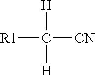
where R1=H, OH or R, where R=alkyl, or is absent.
Claims (20)
Priority Applications (1)
| Application Number | Priority Date | Filing Date | Title |
|---|---|---|---|
| US13/331,211 US8609039B2 (en) | 2006-01-19 | 2011-12-20 | Microfluidic systems and control methods |
Applications Claiming Priority (4)
| Application Number | Priority Date | Filing Date | Title |
|---|---|---|---|
| US76055206P | 2006-01-19 | 2006-01-19 | |
| US11/594,444 US7976795B2 (en) | 2006-01-19 | 2006-11-08 | Microfluidic systems |
| US13/152,881 US8101428B2 (en) | 2006-01-19 | 2011-06-03 | Microfluidic systems and control methods |
| US13/331,211 US8609039B2 (en) | 2006-01-19 | 2011-12-20 | Microfluidic systems and control methods |
Related Parent Applications (1)
| Application Number | Title | Priority Date | Filing Date |
|---|---|---|---|
| US11/594,444 Continuation-In-Part US7976795B2 (en) | 2006-01-19 | 2006-11-08 | Microfluidic systems |
Publications (2)
| Publication Number | Publication Date |
|---|---|
| US20120128549A1 US20120128549A1 (en) | 2012-05-24 |
| US8609039B2 true US8609039B2 (en) | 2013-12-17 |
Family
ID=46064539
Family Applications (1)
| Application Number | Title | Priority Date | Filing Date |
|---|---|---|---|
| US13/331,211 Active 2027-05-07 US8609039B2 (en) | 2006-01-19 | 2011-12-20 | Microfluidic systems and control methods |
Country Status (1)
| Country | Link |
|---|---|
| US (1) | US8609039B2 (en) |
Cited By (9)
| Publication number | Priority date | Publication date | Assignee | Title |
|---|---|---|---|---|
| US20140197339A1 (en) * | 2013-01-15 | 2014-07-17 | The Regents Of The University Of California | Lifting gate polydimethylsiloxane microvalves and pumps for microfluidic control |
| US20140251879A1 (en) * | 2002-04-17 | 2014-09-11 | Cytonome/St, Llc | Method and apparatus for sorting particles |
| US20150204774A1 (en) * | 2012-07-18 | 2015-07-23 | Sony Corporation | Microparticle sorting apparatus, microchip for sorting microparticles and microparticle sorting method |
| US20150367346A1 (en) * | 2013-10-01 | 2015-12-24 | Owl biomedical, Inc. | Cell sorting system using microfabricated components |
| WO2018005647A1 (en) * | 2016-06-28 | 2018-01-04 | Georgia Tech Research Corporation | Systems and methods for high-throughput cell screening |
| US9943847B2 (en) | 2002-04-17 | 2018-04-17 | Cytonome/St, Llc | Microfluidic system including a bubble valve for regulating fluid flow through a microchannel |
| US10029263B2 (en) | 2002-04-17 | 2018-07-24 | Cytonome/St, Llc | Method and apparatus for sorting particles |
| US10994273B2 (en) | 2004-12-03 | 2021-05-04 | Cytonome/St, Llc | Actuation of parallel microfluidic arrays |
| US11253854B2 (en) | 2017-10-20 | 2022-02-22 | Hewlett-Packard Development Company, L.P. | Microfluidic device |
Families Citing this family (24)
| Publication number | Priority date | Publication date | Assignee | Title |
|---|---|---|---|---|
| US9371965B2 (en) | 2012-02-21 | 2016-06-21 | Fluidigm Corporation | Method and systems for microfluidic logic devices |
| US9987576B2 (en) | 2012-12-10 | 2018-06-05 | University Of Virginia Patent Foundation | Frequency-based filtering of mechanical actuation using fluidic device |
| WO2015073999A1 (en) * | 2013-11-18 | 2015-05-21 | Integenx Inc. | Cartridges and instruments for sample analysis |
| US10220387B2 (en) * | 2013-12-05 | 2019-03-05 | The General Hospital Corporation | Modular instrumentation for analyzing biological fluids |
| JP6506907B2 (en) | 2014-02-10 | 2019-04-24 | 株式会社エンプラス | Liquid handling device |
| WO2015125158A2 (en) * | 2014-02-21 | 2015-08-27 | Shilps Sciences Private Limited | A micro-droplet array for multiple screening of a sample |
| FR3040141B1 (en) * | 2015-08-20 | 2020-02-14 | Commissariat A L'energie Atomique Et Aux Energies Alternatives | FLUIDIC CARD COMPRISING AT LEAST ONE FLUIDIC VALVE |
| US10378526B2 (en) * | 2015-12-21 | 2019-08-13 | Funai Electric Co., Ltd | Method and apparatus for metering and vaporizing fluids |
| US10344747B2 (en) * | 2015-12-21 | 2019-07-09 | Funai Electric Co., Ltd. | Method and apparatus for metering and vaporizing a fluid |
| WO2017180660A1 (en) * | 2016-04-11 | 2017-10-19 | Altopa, Inc. | Secure portable, on-demand, microfluidic mixing and dispensing device |
| US10240688B2 (en) * | 2016-06-29 | 2019-03-26 | Ecole Polytechnique Federale De Lausanne (Epfl) | Device having a plurality of latching micro-actuators and method of operating the same |
| CN109475864B (en) * | 2016-06-29 | 2022-03-04 | 美天施生物科技有限两合公司 | Multi-stage disposable cartridge for biological samples |
| BR122020022711B1 (en) | 2016-11-07 | 2021-09-14 | The Climate Corporation | AGRICULTURAL IMPLEMENTATION AND METHOD |
| USD802992S1 (en) | 2017-01-16 | 2017-11-21 | Altopa, Inc. | Blend machine |
| EP3366370A1 (en) * | 2017-02-22 | 2018-08-29 | Briefcase Biotec GmbH | Device for the synthesis of oligonucleotides |
| WO2018194660A1 (en) * | 2017-04-21 | 2018-10-25 | Hewlett-Packard Development Company, L.P. | Health assessment cards |
| US10471427B2 (en) * | 2017-04-24 | 2019-11-12 | Biorep Technologies, Inc. | Fluidic manifold cartridge system |
| USD873068S1 (en) | 2017-07-16 | 2020-01-21 | Altopa, Inc. | Blend device |
| CA3104255C (en) * | 2018-07-10 | 2023-10-31 | Precision Planting Llc | Agricultural sampling system and related methods |
| US11135392B2 (en) * | 2018-12-05 | 2021-10-05 | Aires Medical LLC | Mechanical ventilator |
| CN110187167B (en) * | 2019-04-30 | 2021-06-11 | 广东石油化工学院 | Method and device for detecting load switch event based on manifold classification |
| US11372481B2 (en) | 2020-04-14 | 2022-06-28 | Ecole Polytechnique Federale De Lausanne (Epfl) | Hydraulically amplified dielectric actuator taxels |
| EP4143528A1 (en) * | 2020-04-30 | 2023-03-08 | Precision Planting LLC | Microfluidic processing system and method of agricultural slurry |
| CN112417723B (en) * | 2020-11-19 | 2024-04-12 | 上海电气集团股份有限公司 | Flow field optimization method, device and storage medium |
Citations (6)
| Publication number | Priority date | Publication date | Assignee | Title |
|---|---|---|---|---|
| US5062942A (en) * | 1989-04-12 | 1991-11-05 | Hitachi, Ltd. | Fluorescence detection type electrophoresis apparatus |
| US20050027184A1 (en) * | 2003-08-01 | 2005-02-03 | Enrique Saldivar | Apparatus and method to measure platelet contractility |
| US20050092662A1 (en) * | 2002-09-09 | 2005-05-05 | Cytonome, Inc. | Implementation of microfluidic components in a microfluidic system |
| US20050214173A1 (en) * | 2004-01-25 | 2005-09-29 | Fluidigm Corporation | Integrated chip carriers with thermocycler interfaces and methods of using the same |
| US20060030796A1 (en) * | 2004-08-03 | 2006-02-09 | Agency For Science, Technology And Research | Method and device for the treatment of biological samples |
| US20090257920A1 (en) * | 2008-04-11 | 2009-10-15 | Fluidigm Corporation | Multilevel microfluidic systems and methods |
-
2011
- 2011-12-20 US US13/331,211 patent/US8609039B2/en active Active
Patent Citations (6)
| Publication number | Priority date | Publication date | Assignee | Title |
|---|---|---|---|---|
| US5062942A (en) * | 1989-04-12 | 1991-11-05 | Hitachi, Ltd. | Fluorescence detection type electrophoresis apparatus |
| US20050092662A1 (en) * | 2002-09-09 | 2005-05-05 | Cytonome, Inc. | Implementation of microfluidic components in a microfluidic system |
| US20050027184A1 (en) * | 2003-08-01 | 2005-02-03 | Enrique Saldivar | Apparatus and method to measure platelet contractility |
| US20050214173A1 (en) * | 2004-01-25 | 2005-09-29 | Fluidigm Corporation | Integrated chip carriers with thermocycler interfaces and methods of using the same |
| US20060030796A1 (en) * | 2004-08-03 | 2006-02-09 | Agency For Science, Technology And Research | Method and device for the treatment of biological samples |
| US20090257920A1 (en) * | 2008-04-11 | 2009-10-15 | Fluidigm Corporation | Multilevel microfluidic systems and methods |
Cited By (18)
| Publication number | Priority date | Publication date | Assignee | Title |
|---|---|---|---|---|
| US10029263B2 (en) | 2002-04-17 | 2018-07-24 | Cytonome/St, Llc | Method and apparatus for sorting particles |
| US20140251879A1 (en) * | 2002-04-17 | 2014-09-11 | Cytonome/St, Llc | Method and apparatus for sorting particles |
| US20150352597A1 (en) * | 2002-04-17 | 2015-12-10 | Cytonome/St, Llc | Method and apparatus for sorting particles |
| US11027278B2 (en) | 2002-04-17 | 2021-06-08 | Cytonome/St, Llc | Methods for controlling fluid flow in a microfluidic system |
| US9550215B2 (en) * | 2002-04-17 | 2017-01-24 | Cytonome/St, Llc | Method and apparatus for sorting particles |
| US10710120B2 (en) * | 2002-04-17 | 2020-07-14 | Cytonome/St, Llc | Method and apparatus for sorting particles |
| US10427159B2 (en) | 2002-04-17 | 2019-10-01 | Cytonome/St, Llc | Microfluidic device |
| US9943847B2 (en) | 2002-04-17 | 2018-04-17 | Cytonome/St, Llc | Microfluidic system including a bubble valve for regulating fluid flow through a microchannel |
| US10029283B2 (en) * | 2002-04-17 | 2018-07-24 | Cytonome/St, Llc | Method and apparatus for sorting particles |
| US10994273B2 (en) | 2004-12-03 | 2021-05-04 | Cytonome/St, Llc | Actuation of parallel microfluidic arrays |
| US20150204774A1 (en) * | 2012-07-18 | 2015-07-23 | Sony Corporation | Microparticle sorting apparatus, microchip for sorting microparticles and microparticle sorting method |
| US9448157B2 (en) * | 2012-07-18 | 2016-09-20 | Sony Corporation | Microparticle sorting apparatus, microchip for sorting microparticles and microparticle sorting method |
| US9791068B2 (en) * | 2013-01-15 | 2017-10-17 | The Regents Of The University Of California | Lifting gate polydimethylsiloxane microvalves and pumps for microfluidic control |
| US20140197339A1 (en) * | 2013-01-15 | 2014-07-17 | The Regents Of The University Of California | Lifting gate polydimethylsiloxane microvalves and pumps for microfluidic control |
| US9604214B2 (en) * | 2013-10-01 | 2017-03-28 | Owl biomedical, Inc. | Cell sorting system using microfabricated components |
| US20150367346A1 (en) * | 2013-10-01 | 2015-12-24 | Owl biomedical, Inc. | Cell sorting system using microfabricated components |
| WO2018005647A1 (en) * | 2016-06-28 | 2018-01-04 | Georgia Tech Research Corporation | Systems and methods for high-throughput cell screening |
| US11253854B2 (en) | 2017-10-20 | 2022-02-22 | Hewlett-Packard Development Company, L.P. | Microfluidic device |
Also Published As
| Publication number | Publication date |
|---|---|
| US20120128549A1 (en) | 2012-05-24 |
Similar Documents
| Publication | Publication Date | Title |
|---|---|---|
| US8609039B2 (en) | Microfluidic systems and control methods | |
| US9151701B2 (en) | Microfluidic systems | |
| JP6904932B2 (en) | Systems and devices for sample analysis | |
| US7416892B2 (en) | Method and system for microfluidic manipulation, amplification and analysis of fluids, for example, bacteria assays and antiglobulin testing | |
| US20070042427A1 (en) | Microfluidic laminar flow detection strip | |
| US20240027487A1 (en) | System, device and methods of sample processing using semiconductor detection chips | |
| CN113441194A (en) | Micro-fluidic detection chip | |
| CN116381220A (en) | Electrochemical immunosensor microfluidic detection cartridge | |
| CN111190022A (en) | Biochemical detection system and detection method based on resonant sensor |
Legal Events
| Date | Code | Title | Description |
|---|---|---|---|
| AS | Assignment |
Owner name: RHEONIX, INC., NEW YORK Free format text: ASSIGNMENT OF ASSIGNORS INTEREST;ASSIGNORS:ZHOU, PENG;YOUNG, LINCOLN C.;REEL/FRAME:027418/0737 Effective date: 20110613 |
|
| AS | Assignment |
Owner name: RHEONIX, INC., NEW YORK Free format text: ASSIGNMENT OF ASSIGNORS INTEREST;ASSIGNORS:ZHOU, PENG;YOUNG, LINCOLN C.;REEL/FRAME:027648/0903 Effective date: 20111221 |
|
| STCF | Information on status: patent grant |
Free format text: PATENTED CASE |
|
| FPAY | Fee payment |
Year of fee payment: 4 |
|
| AS | Assignment |
Owner name: GRASSHOPPER BANK, N.A., NEW YORK Free format text: SECURITY INTEREST;ASSIGNOR:RHEONIX, INC.;REEL/FRAME:056254/0074 Effective date: 20210517 |
|
| MAFP | Maintenance fee payment |
Free format text: PAYMENT OF MAINTENANCE FEE, 8TH YR, SMALL ENTITY (ORIGINAL EVENT CODE: M2552); ENTITY STATUS OF PATENT OWNER: SMALL ENTITY Year of fee payment: 8 |