US8608740B2 - Bolt for use with an external fixator - Google Patents
Bolt for use with an external fixator Download PDFInfo
- Publication number
- US8608740B2 US8608740B2 US13/180,916 US201113180916A US8608740B2 US 8608740 B2 US8608740 B2 US 8608740B2 US 201113180916 A US201113180916 A US 201113180916A US 8608740 B2 US8608740 B2 US 8608740B2
- Authority
- US
- United States
- Prior art keywords
- pin
- edges
- opening
- section
- bolt
- Prior art date
- Legal status (The legal status is an assumption and is not a legal conclusion. Google has not performed a legal analysis and makes no representation as to the accuracy of the status listed.)
- Active
Links
Images


Classifications
-
- A—HUMAN NECESSITIES
- A61—MEDICAL OR VETERINARY SCIENCE; HYGIENE
- A61B—DIAGNOSIS; SURGERY; IDENTIFICATION
- A61B17/00—Surgical instruments, devices or methods, e.g. tourniquets
- A61B17/56—Surgical instruments or methods for treatment of bones or joints; Devices specially adapted therefor
- A61B17/58—Surgical instruments or methods for treatment of bones or joints; Devices specially adapted therefor for osteosynthesis, e.g. bone plates, screws, setting implements or the like
- A61B17/60—Surgical instruments or methods for treatment of bones or joints; Devices specially adapted therefor for osteosynthesis, e.g. bone plates, screws, setting implements or the like for external osteosynthesis, e.g. distractors, contractors
- A61B17/64—Devices extending alongside the bones to be positioned
- A61B17/6458—Devices extending alongside the bones to be positioned with pin-clamps fixed at ends of connecting element
-
- A—HUMAN NECESSITIES
- A61—MEDICAL OR VETERINARY SCIENCE; HYGIENE
- A61B—DIAGNOSIS; SURGERY; IDENTIFICATION
- A61B17/00—Surgical instruments, devices or methods, e.g. tourniquets
- A61B17/56—Surgical instruments or methods for treatment of bones or joints; Devices specially adapted therefor
- A61B17/58—Surgical instruments or methods for treatment of bones or joints; Devices specially adapted therefor for osteosynthesis, e.g. bone plates, screws, setting implements or the like
- A61B17/60—Surgical instruments or methods for treatment of bones or joints; Devices specially adapted therefor for osteosynthesis, e.g. bone plates, screws, setting implements or the like for external osteosynthesis, e.g. distractors, contractors
- A61B17/64—Devices extending alongside the bones to be positioned
- A61B17/6466—Devices extending alongside the bones to be positioned with pin-clamps movable along a solid connecting rod
Definitions
- the present invention relates to a bolt or pin clamp for use with an external fixator.
- an external fixator comprises rings or plates also designated as fixation plates connected by threaded rods or struts to manipulate angulations, translation and length discrepancies of bones.
- fixation plates are connected to bony structure by means of pins which usually extend through the rings.
- the pins are connected to the plates by means of bolts and nuts.
- pins having different diameters will be used depending on the special situation near the fracture. For that reason several bolts with openings having respective diameters have to be used.
- U.S. Pat. Nos. 5,630,814 and 5,681,309 provide one solution to adapt a bolt in order to be used to clamp different pin or wire sizes.
- the bolt comprises an opening which is provided with cross section that is tear drop-shaped.
- the pin is in connection with the bolt and the fixation plate via three contact zones all of which are provided with respective surfaces.
- the shape of the drop shaped opening as well as the fact that the pin is clamped via plane surfaces has several drawbacks. Due to the shape it may be possible that it comes to gaping such that the sidewalls of the opening will be moved with respect to each other. Furthermore it is possible that the area above the opening fractures in case extraordinary tightening forces are necessary.
- the process of tightening a pre-aligned pin shall, as well as the connection between the pin and the bolt, shall be improved.
- a bolt that is adapted to clamp a pin to an external fixator system which comprises a shaft having a threaded section, a head section and a pin opening that is arranged opposite the threaded section and accommodates and clamps a pin or a wire to a plate of an external fixator.
- the plate comprises at least one opening which accommodates the shaft and a surface against which the pin or the wire is clamped by means of the bolt, in particular by means of the pin opening.
- the pin opening comprises at least two edges extending essentially along the same direction as the pin opening such that the pin or wire to be clamped is in contact with the edges. The pin is thereby clamped with the edges and the surface of the plate. Preferably the edges are arranged at a distance from each other.
- the pin opening comprises exactly two edges, which allows centering the pin or wire in an automatic manner.
- the pin opening is limited by a surface, wherein the edges extend from said surface or wherein the edges are part of the surface.
- the pin opening comprises a groove extending from the surface of the pin opening into the bolt such that two edges will be provided. Thereby the edges are part of the surface of the pin opening.
- Such a structure can be manufactured very efficiently.
- edges have the shape of a ridge which extends from the surface into the inner width of the pin opening.
- edges extend only partly over the length of the pin opening and/or the edges are interrupted over the length of the pin opening.
- one edge comprises several sections which are arranged in a line one behind the other.
- the shaft extends along a middle axis and the edges extend angular to the middle axis such that the distance as viewed perpendicular to the middle axis remains constant.
- the pin opening has a circular cross-section opposite the edges, such that the pin or wire will be centred before tightening.
- the bolt comprises a shaft section that is arranged between the threaded section and the head section, wherein the pin opening is arranged such that its cross-section extends into the head section and into the shaft section.
- the pin opening is arranged such that its cross-section extends into the head section and into the threaded section.
- An external fixator system comprising at least one fixation plate with a plurality of openings and at least one pin to be attached to the fixation plate, wherein the pin is attached by means of a bolt as described above and by means of a corresponding nut, wherein the bolt extends through said opening in the plate and clamps the pin by means of said pin opening with the edges and a surface of the fixation plate.
- FIG. 1 shows a side view of the bolt for use with an external fixator
- FIG. 2 shows a perspective view of the bolt according to FIG. 1 ;
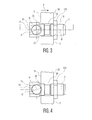
- FIG. 3 shows a side view of an assembly of the bolt according to FIG. 1 with a pin and a schematic view of a fixation plate;
- FIG. 4 shows a side view of the bolt according to FIG. 1 with a pin and a schematic fixation plate
- FIG. 5 shows a cross-sectional view of the assembly of FIG. 3 along lines 5 - 5 ;
- FIG. 6 is a top view of the assembly of FIG. 3 .
- FIGS. 1 and 2 there is shown a bolt 1 or a screw for clamping a wire or a pin to a fixation plate 3 in an external fixator system.
- the bolt 1 extends along a middle axis M and comprises a shaft having a threaded section 10 , a head section 11 and a pin opening 13 .
- the pin opening 13 serves to accommodate and to clamp a pin 2 or a wire to an external fixator.
- the bolt 1 extends through an opening 30 in a fixation plate or ring 3 as seen in FIG. 3 .
- the opening thereby extends from a top surface 31 to a bottom surface 32 .
- the bolt 1 is attached by means of a nut which comes into contact with the bottom surfaces 32 .
- Upon tightening the nut the bolt 1 will be moved with its head section 11 along the middle axis M towards the top surface 31 whereupon the pin 2 will be clamped by means of the pin opening 13 and the top surface 31 . This will be further explained below with FIGS. 3 and 4 .
- the pin opening 13 extends along a middle axis N preferably perpendicular to axis M and has substantially a circular cross-section.
- the pin opening 13 comprises an inner surface 16 defining said pin opening.
- the pin opening 13 comprises at least two edges 15 which preferably extend in substantially the same direction as the pin opening itself, namely along or parallel to middle axis N.
- edges 15 are provided.
- edge includes everything that it is arranged aligned in the respective direction. In case the edge is subdivided or interrupted along its length this is still to be considered as one edge with multiple sections.
- the edges 15 have the same length as the pin opening 13 such that uninterrupted edges 15 can be provided.
- edges 15 can be arranged such that they are part of the surface 16 as it is shown in the figures. Thereby the edges 15 are provided by means of a channel or groove 14 which extends from the surface 16 of the pin opening 13 into the bolt 1 .
- the groove 14 has a cross-section of a semi-circle as such a structure can be manufactured very easily. However, other cross-sections such as rectangular or polygonal may also be possible.
- edges 15 can also be provided such that they extend from the surface 16 into the pin opening 13 . This means that separate edge elements 15 such as ridges extending from the surface 16 of said pin opening 13 .
- the edges 15 extend preferably over the whole length of the pin opening 13 without an interruption. Hence there is a contact with the pin that is inserted into the pin opening 13 over the whole length of that part of the pin that extends into the opening.
- the pin is in contact with the top surface in the area that surrounds the opening 30 in the plate 3 .
- the head section 12 is larger in direction of the middle axis N than the diameter of the opening 30 so that the edges 15 extend over the opening 30 when viewed along middle axis M.
- the pin opening 13 is therefore larger than the diameter of the opening 30 in the plate.
- edges 15 extend only over parts of said pin opening 13 or that the edges are partly interrupted. Thereby each of the edges 15 would comprise a plurality of edged pieces which are arranged collinear to each other in order to provide said edges 15 . Alternatively an edge 15 may also be provided by means of several embossments which are also arranged one behind the other.
- edges 15 extend in substantially the same direction as the pin opening 13 , namely parallel to middle axis N.
- a virtual plane E that extends perpendicular to the middle axis N of the bolt 1 as well as the middle axis M itself are used in the following to define the position of the edges 15 .
- the virtual plane E is substantially parallel to the top surface 31 of the external fixator.
- Both edges 15 are arranged at the same distance from the virtual plane E and also at the same distance from the middle axis M. Thereby the pin can be arranged in a very stable and well defined manner.
- the width of the head along plane E is preferably greater than the diameter of hole 30
- the edges 15 can also be arranged at an angle to the middle axis N so that the edges 15 extend at a constant distance perpendicular to the middle axis M, i.e. in a common plane which is parallel to virtual plane E, but angular with respect to the middle axis. Thereby it is possible that the edges 15 cross or touch each other somewhere in the opening 13 .
- the bolt can additionally have a shaft section 11 which is arranged between the threaded section 10 and the head section 12 .
- the shaft section can have a constant diameter or it may comprises a first portion 11 ′ and a second portion 11 ′′ with different diameters.
- the first portion 11 ′ adjoining the threaded section 10 has a smaller diameter than the second portion 11 ′′. It may also be possible to arrange the portion with the larger diameter next to the threaded portion 10 and the portion with the smaller diameter next to the head portion 12 .
- the threaded section 10 may also include a shaft part having a chamfered edge 18 which allows a very easy positioning within the opening 30 .
- the pin opening 13 is arranged such that it extends within the head section 12 and also with then shaft section 11 and/or the threaded section 10 .
- the head section 12 has substantially a cubic shape so that the head section is graspable by means of a tool such as a wrench in order to provide a counter-torque when a nut 50 is tightened.
- FIGS. 3-6 show a pin 2 a in FIGS. 3 and 2 b in FIG. 4 within the pin opening 13 whereby the pin will be clamped by means the bolt 1 and nut 50 to the fixator plate 3 .
- the nut 50 is in connection with the threaded section 10 of the bolt.
- a force F acts onto the bolt 1 and it will be moved with the head section 12 towards the top surface 31 of the fixator plate 3 .
- the movement of the bolt 1 is collinear to the middle axis M of the opening 30 in plate 3 .
- As the counter torque can be compensated by means of a tool that engages head section 12 there will be no rotation of the bolt 1 while tightening nut 50 .
- the arrangement has the advantage that the pin 2 can be aligned before tightening and during the tightening process the alignment of the pins 2 a , 2 b will not be disturbed.
- the pins 2 a , 2 b are mainly in contact with elements, namely the edges 15 and surface 30 that move parallel to each other. Thereby the pins 2 a , 2 b will be clamped by means of the edges 15 and by means of the top surface 31 .
- the surface 20 of the pins 2 a , 2 b is therefore in contact with the top surface 31 and with the edges 15 .
- the pins 2 a , 2 b will be clamped at every cross-section at three different positions which means that the pin 2 will be automatically centered within the opening and therefore a reliable connection can be established.
- edges 15 Due to the arrangement of the edges 15 it is also possible to clamp pins with different diameters, since the edges 15 are arranged such that they are always in contact with the surface 20 of the pin, irrespective of its diameter. In the case of pin 2 a with a smaller diameter shown in FIG. 4 the bottom surface 52 of bolt 1 will be moved closer to the top surface 31 of the fixation plate 3 .
- the central axis of the pin is, depending on the diameter of the pin, is shifted or offset from the middle axis N of the opening 16 .
- the pin itself is however always in contact with the top surface 31 of the fixation plate 3 which means that the pin central axis is always arranged on the same plane along middle axis M irrespective of its diameter.
- the pin 2 is therefore always in contact with the top surface 31 of the fixation plate 3 at a point which is shown with reference numeral 20 .
- the pin 2 is in contact with the external fixator by means of its surface which contacts the edges 15 and the top surface 31 . Thereby three contact zones are established.
- the bolt 1 with the pin opening 16 and the edges 15 has the advantage that it is possible to clamp pins with different diameter whereby the contact zones between the pin 2 and the bolt 1 remain at the same position. This means that it is possible to provide reproducible connections between the pin and the bolt. Furthermore the same tightening force can be applied in order to achieve constant clamping force onto the pin.
- edges 15 are also possible to provide the edges 15 such that they impinge into the surface of the wire or pin which means that a higher clamping force will be achieved.
- the circular cross-section of the pin opening 13 is particularly advantageous as the pin 2 is centred with the section of the opening 13 opposite the edges 15 . Upon tightening the pin 2 then comes into contact with the edges 15 which ensure that the pin is aligned accordingly. This means the pin is pre-aligned by means of the circular pin opening 13 before it will be clamped.
- the bolt is preferably made out of metal preferably such as stainless steel, titanium or aluminium.
Abstract
Description
Claims (22)
Applications Claiming Priority (6)
| Application Number | Priority Date | Filing Date | Title |
|---|---|---|---|
| EP10174314 | 2010-08-27 | ||
| EP10174314.4 | 2010-08-27 | ||
| EP10174314 | 2010-08-27 | ||
| EP11169440.2 | 2011-06-10 | ||
| EP11169440.2A EP2422727B1 (en) | 2010-08-27 | 2011-06-10 | Bolt for use with an external fixator |
| EP11169440 | 2011-06-10 |
Publications (2)
| Publication Number | Publication Date |
|---|---|
| US20120053584A1 US20120053584A1 (en) | 2012-03-01 |
| US8608740B2 true US8608740B2 (en) | 2013-12-17 |
Family
ID=43410506
Family Applications (1)
| Application Number | Title | Priority Date | Filing Date |
|---|---|---|---|
| US13/180,916 Active US8608740B2 (en) | 2010-08-27 | 2011-07-12 | Bolt for use with an external fixator |
Country Status (2)
| Country | Link |
|---|---|
| US (1) | US8608740B2 (en) |
| EP (1) | EP2422727B1 (en) |
Cited By (4)
| Publication number | Priority date | Publication date | Assignee | Title |
|---|---|---|---|---|
| US9445841B2 (en) * | 2014-12-10 | 2016-09-20 | Texas Scottish Rite Hospital For Children | Wire tensioner tip for use with wire fixation bolt |
| US10010350B2 (en) | 2016-06-14 | 2018-07-03 | Stryker European Holdings I, Llc | Gear mechanisms for fixation frame struts |
| US10874433B2 (en) | 2017-01-30 | 2020-12-29 | Stryker European Holdings I, Llc | Strut attachments for external fixation frame |
| WO2022201017A1 (en) | 2021-03-22 | 2022-09-29 | Nelson Saldanha Kiran Antony | Stable locking fixation of threaded bone pins and other components of ring external fixator |
Families Citing this family (1)
| Publication number | Priority date | Publication date | Assignee | Title |
|---|---|---|---|---|
| US9962188B2 (en) | 2013-10-29 | 2018-05-08 | Cardinal Health 247. Inc. | External fixation system and methods of use |
Citations (17)
| Publication number | Priority date | Publication date | Assignee | Title |
|---|---|---|---|---|
| US4244360A (en) * | 1979-10-22 | 1981-01-13 | Ace Orthopedic Manufacturing, Inc. | Orthopedic fixation pin holder |
| US4870957A (en) * | 1988-12-27 | 1989-10-03 | Marlowe Goble E | Ligament anchor system |
| US5053034A (en) * | 1990-08-03 | 1991-10-01 | Sven Olerud | Spinal joint |
| US5306275A (en) * | 1992-12-31 | 1994-04-26 | Bryan Donald W | Lumbar spine fixation apparatus and method |
| US5451225A (en) * | 1993-06-10 | 1995-09-19 | Texas Scottish Rite Hospital For Crippled Children | Fastener for external fixation device wires and pins |
| US5681309A (en) | 1993-06-10 | 1997-10-28 | Texas Scottish Rite Hospital For Crippled Children | Distractor mechanism for external fixation device |
| US5746741A (en) | 1996-05-06 | 1998-05-05 | Tufts University | External fixator system |
| US5921985A (en) * | 1998-02-10 | 1999-07-13 | Texas Scottish Rite Hospital | External fixation device and method |
| US6113600A (en) | 1995-06-06 | 2000-09-05 | Denek Medical, Inc. | Device for linking adjacent rods in spinal instrumentation |
| US6217578B1 (en) | 1999-10-19 | 2001-04-17 | Stryker Spine S.A. | Spinal cross connector |
| US6533785B1 (en) | 1998-05-07 | 2003-03-18 | Synthes (Usa) | Clamp for an external bone fixation device |
| US20050234450A1 (en) * | 2004-04-15 | 2005-10-20 | Barker B T | Transfer ring for offset tapered 3D connector |
| US20060247629A1 (en) | 2005-04-27 | 2006-11-02 | Maughan Thomas J | Bone fixation apparatus |
| US20080195122A1 (en) * | 2007-02-09 | 2008-08-14 | Altiva Corporation | Connector |
| WO2009004347A1 (en) | 2007-07-03 | 2009-01-08 | Raffan, Peter | Pin clamp |
| US20090228006A1 (en) | 2005-09-15 | 2009-09-10 | Mikai S.P.A. | Apparatus for Treating Malformative and Traumatic Conditions Affecting the Knee Area |
| US20100160965A1 (en) * | 2008-12-22 | 2010-06-24 | Zimmer Spine, Inc. | Bone Anchor Assembly and Methods of Use |
-
2011
- 2011-06-10 EP EP11169440.2A patent/EP2422727B1/en active Active
- 2011-07-12 US US13/180,916 patent/US8608740B2/en active Active
Patent Citations (19)
| Publication number | Priority date | Publication date | Assignee | Title |
|---|---|---|---|---|
| US4244360A (en) * | 1979-10-22 | 1981-01-13 | Ace Orthopedic Manufacturing, Inc. | Orthopedic fixation pin holder |
| US4870957A (en) * | 1988-12-27 | 1989-10-03 | Marlowe Goble E | Ligament anchor system |
| US5053034A (en) * | 1990-08-03 | 1991-10-01 | Sven Olerud | Spinal joint |
| US5306275A (en) * | 1992-12-31 | 1994-04-26 | Bryan Donald W | Lumbar spine fixation apparatus and method |
| US5451225A (en) * | 1993-06-10 | 1995-09-19 | Texas Scottish Rite Hospital For Crippled Children | Fastener for external fixation device wires and pins |
| US5630814A (en) * | 1993-06-10 | 1997-05-20 | Texas Scottish Rite Hospital For Crippled Children | Fastener for external fixation device wires and pins |
| US5681309A (en) | 1993-06-10 | 1997-10-28 | Texas Scottish Rite Hospital For Crippled Children | Distractor mechanism for external fixation device |
| US6113600A (en) | 1995-06-06 | 2000-09-05 | Denek Medical, Inc. | Device for linking adjacent rods in spinal instrumentation |
| US5746741A (en) | 1996-05-06 | 1998-05-05 | Tufts University | External fixator system |
| US5921985A (en) * | 1998-02-10 | 1999-07-13 | Texas Scottish Rite Hospital | External fixation device and method |
| US6533785B1 (en) | 1998-05-07 | 2003-03-18 | Synthes (Usa) | Clamp for an external bone fixation device |
| US6217578B1 (en) | 1999-10-19 | 2001-04-17 | Stryker Spine S.A. | Spinal cross connector |
| US20050234450A1 (en) * | 2004-04-15 | 2005-10-20 | Barker B T | Transfer ring for offset tapered 3D connector |
| US20060247629A1 (en) | 2005-04-27 | 2006-11-02 | Maughan Thomas J | Bone fixation apparatus |
| US20060247622A1 (en) | 2005-04-27 | 2006-11-02 | Maughan Thomas J | Bone fixation apparatus |
| US20090228006A1 (en) | 2005-09-15 | 2009-09-10 | Mikai S.P.A. | Apparatus for Treating Malformative and Traumatic Conditions Affecting the Knee Area |
| US20080195122A1 (en) * | 2007-02-09 | 2008-08-14 | Altiva Corporation | Connector |
| WO2009004347A1 (en) | 2007-07-03 | 2009-01-08 | Raffan, Peter | Pin clamp |
| US20100160965A1 (en) * | 2008-12-22 | 2010-06-24 | Zimmer Spine, Inc. | Bone Anchor Assembly and Methods of Use |
Non-Patent Citations (1)
| Title |
|---|
| Search report of EP 10174314 dated Feb. 11, 2011. |
Cited By (6)
| Publication number | Priority date | Publication date | Assignee | Title |
|---|---|---|---|---|
| US9445841B2 (en) * | 2014-12-10 | 2016-09-20 | Texas Scottish Rite Hospital For Children | Wire tensioner tip for use with wire fixation bolt |
| US10010350B2 (en) | 2016-06-14 | 2018-07-03 | Stryker European Holdings I, Llc | Gear mechanisms for fixation frame struts |
| US11504160B2 (en) | 2016-06-14 | 2022-11-22 | Stryker European Operations Holdings Llc | Gear mechanisms for fixation frame struts |
| US10874433B2 (en) | 2017-01-30 | 2020-12-29 | Stryker European Holdings I, Llc | Strut attachments for external fixation frame |
| US11723690B2 (en) | 2017-01-30 | 2023-08-15 | Stryker European Operations Holdings Llc | Strut attachments for external fixation frame |
| WO2022201017A1 (en) | 2021-03-22 | 2022-09-29 | Nelson Saldanha Kiran Antony | Stable locking fixation of threaded bone pins and other components of ring external fixator |
Also Published As
| Publication number | Publication date |
|---|---|
| EP2422727B1 (en) | 2016-03-23 |
| US20120053584A1 (en) | 2012-03-01 |
| EP2422727A1 (en) | 2012-02-29 |
Similar Documents
| Publication | Publication Date | Title |
|---|---|---|
| EP2446841B1 (en) | Bolt and tool with anti-torque features | |
| US8608740B2 (en) | Bolt for use with an external fixator | |
| USRE49771E1 (en) | Bone plate | |
| US8172840B2 (en) | External fixation component | |
| US6432109B1 (en) | Connection device for osteosynthesis | |
| US8323321B2 (en) | Implant and bone screw having interlocking cams | |
| US9023045B2 (en) | Bolt and tool with anti-torque features | |
| US20110060372A1 (en) | Bone fixing device | |
| GB2479282A (en) | A deformable bone fixation device | |
| EP2438869B1 (en) | Coupling element for an external fixator | |
| WO2009127663A2 (en) | Orthopedic fixation plate | |
| US11761472B2 (en) | Nut restrainer, centering tool, and methods of use | |
| US20040238558A1 (en) | Device for Connecting Ends of Bars | |
| JP4885030B2 (en) | Joining method and joining confirmation device for joint fitting of heavy temporary structure | |
| US8904606B2 (en) | Cord gripping mechanism and method | |
| CN106826650A (en) | A kind of special spanner and multifunctional wrench | |
| KR20100113484A (en) | Lock ring for an osteosynthesis device and osteosynthesis device including such ring | |
| US8287548B2 (en) | Wire fixation device | |
| KR101199334B1 (en) | Arrange pin of connecting holes | |
| JP2018027596A (en) | spanner | |
| CN101922278A (en) | Section connecting member and use method thereof |
Legal Events
| Date | Code | Title | Description |
|---|---|---|---|
| AS | Assignment |
Owner name: STRYKER TRAUMA SA, SWITZERLAND Free format text: ASSIGNMENT OF ASSIGNORS INTEREST;ASSIGNORS:BUETIKOFER, MANFRED;BOUQUET, JOEL;LEHMANN, PHILIPPE;REEL/FRAME:026618/0939 Effective date: 20110614 |
|
| STCF | Information on status: patent grant |
Free format text: PATENTED CASE |
|
| AS | Assignment |
Owner name: STRYKER EUROPEAN HOLDINGS I, LLC, MICHIGAN Free format text: NUNC PRO TUNC ASSIGNMENT;ASSIGNOR:STRYKER EUROPEAN HOLDINGS V, LLC;REEL/FRAME:037153/0168 Effective date: 20151008 Owner name: STRYKER EUROPEAN HOLDINGS V, LLC, MICHIGAN Free format text: NUNC PRO TUNC ASSIGNMENT;ASSIGNOR:STRYKER TRAUMA SA;REEL/FRAME:037153/0001 Effective date: 20151008 |
|
| FPAY | Fee payment |
Year of fee payment: 4 |
|
| AS | Assignment |
Owner name: STRYKER EUROPEAN OPERATIONS HOLDINGS LLC, MICHIGAN Free format text: CHANGE OF NAME;ASSIGNOR:STRYKER EUROPEAN HOLDINGS III, LLC;REEL/FRAME:052860/0716 Effective date: 20190226 Owner name: STRYKER EUROPEAN HOLDINGS III, LLC, DELAWARE Free format text: NUNC PRO TUNC ASSIGNMENT;ASSIGNOR:STRYKER EUROPEAN HOLDINGS I, LLC;REEL/FRAME:052861/0001 Effective date: 20200519 |
|
| MAFP | Maintenance fee payment |
Free format text: PAYMENT OF MAINTENANCE FEE, 8TH YEAR, LARGE ENTITY (ORIGINAL EVENT CODE: M1552); ENTITY STATUS OF PATENT OWNER: LARGE ENTITY Year of fee payment: 8 |