US8600374B1 - Sterilizable wireless tracking and communication device and method for manufacturing - Google Patents
Sterilizable wireless tracking and communication device and method for manufacturing Download PDFInfo
- Publication number
- US8600374B1 US8600374B1 US13/371,416 US201213371416A US8600374B1 US 8600374 B1 US8600374 B1 US 8600374B1 US 201213371416 A US201213371416 A US 201213371416A US 8600374 B1 US8600374 B1 US 8600374B1
- Authority
- US
- United States
- Prior art keywords
- sterilization
- housing
- communication device
- wireless communication
- circuit board
- Prior art date
- Legal status (The legal status is an assumption and is not a legal conclusion. Google has not performed a legal analysis and makes no representation as to the accuracy of the status listed.)
- Active
Links
Images


Classifications
-
- H—ELECTRICITY
- H04—ELECTRIC COMMUNICATION TECHNIQUE
- H04M—TELEPHONIC COMMUNICATION
- H04M1/00—Substation equipment, e.g. for use by subscribers
- H04M1/02—Constructional features of telephone sets
- H04M1/18—Telephone sets specially adapted for use in ships, mines, or other places exposed to adverse environment
-
- H—ELECTRICITY
- H04—ELECTRIC COMMUNICATION TECHNIQUE
- H04M—TELEPHONIC COMMUNICATION
- H04M1/00—Substation equipment, e.g. for use by subscribers
- H04M1/02—Constructional features of telephone sets
- H04M1/17—Hygienic or sanitary devices on telephone equipment
-
- H—ELECTRICITY
- H04—ELECTRIC COMMUNICATION TECHNIQUE
- H04M—TELEPHONIC COMMUNICATION
- H04M2250/00—Details of telephonic subscriber devices
- H04M2250/12—Details of telephonic subscriber devices including a sensor for measuring a physical value, e.g. temperature or motion
Definitions
- the present invention is related to wireless tracking and communication devices and methods for manufacturing wireless communication devices. More specifically, the present invention is related to sterilizable wireless tracking and communication devices and methods for manufacturing sterilizable wireless communication devices.
- a typical radio frequency identification system includes at least multiple tagged objects, each of which transmits a signal, multiple receivers for receiving the transmissions from the tagged objects, and a processing means for analyzing the transmissions to determine the locations of the tagged objects within a predetermined environment.
- Medical equipment subject to extreme temperatures includes surgical kits or surgical trays which are typically sterilized in an autoclave at high temperatures to destroy any living organisms (bacteria, fungi, viruses and spores). Autoclaves generally use heat and high pressure to destroy the living organisms. These high temperatures are often in excess of 120 degrees Fahrenheit, and as high as 300 degrees Fahrenheit.
- the surgical trays are typically composed of stainless steel, aluminum or another metal.
- Various surgical instruments are contained within the surgical tray.
- An example of such a tray is disclosed in Wood, U.S. Pat. No. 6,827,913, for a Modular Sterilization Tray Systems For Medical Instruments.
- Nicholson, et al., U.S. Pat. No. 6,255,949, for a High Temperature RFID Tag discloses an RFID tag that is capable of withstanding temperatures of ⁇ 40 degrees Celsius to 300 degrees Celsius.
- the tag is placed within a housing composed of a high thermally resistant material such as RYTON PPS compound or TEFLON.
- the present invention has recognized that operating a wireless tracking system in a sterilization environment creates unique problems.
- the present invention provides a novel solution to that problem in the form of a water-proof sterilizable tag.
- One aspect of the present invention is a wireless communication device comprising a circuit board with a coating, a top housing having a protrusion, a bottom housing for engagement with the top housing, the bottom housing having a side wall, and a gasket with a designed interference for sealing a chamber defined by the top housing and the bottom housing.
- the circuit board is positioned within the chamber and the protrusion of the top housing and the side wall of the bottom housing form a vapor trap.
- a wireless communication device comprising a circuit board with a paralyne coating, a top housing having a protrusion extending downward, a bottom housing for engagement with the top housing, the bottom housing having a side wall, and a TPE gasket with a designed interference for sealing a chamber defined by the top housing and the bottom housing.
- the circuit board is positioned within the chamber and the protrusion of the top housing and the side wall of the bottom housing form a vapor trap.
- Another aspect of the present invention is a method for forming a water-proof wireless communication device.
- the method includes coating a circuit board with a coating material to form a coated circuit board.
- the method also includes placing a gasket around the coated circuit board.
- the method also includes placing the coated circuit board and gasket in a bottom housing.
- the method also includes mating a top housing with the bottom housing.
- the method also includes attaching the top housing with the bottom housing to form a water-proof wireless communication device.
- the tag includes a circuit board with a paralyne coating, a top housing having a protrusion extending downward, a bottom housing for engagement with the top housing, the bottom housing having a side wall, and a TPE gasket with a designed interference for sealing a chamber defined by the top housing and the bottom housing.
- the circuit board is positioned within the chamber and the protrusion of the top housing and the side wall of the bottom housing form a vapor trap.
- the housing is preferably composed of a polyetherimide resin material.
- the tracking tag preferably transmits a radiofrequency transmission of approximately 2.48 GigaHertz, and each of the plurality of network sensors communicates utilizing an 802.15.4 protocol. Alternatively, the tracking tag transmits an ultrasound or infrared transmission.
- FIG. 1 is schematic view of a wireless asset tracking system.
- FIG. 2 is a multi-floor view of a facility employing a wireless asset tracking system.
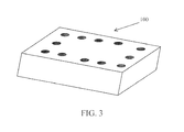
- FIG. 3 is an illustration of a surgical tray.
- FIG. 3A is an illustration of an interior of a surgical tray.
- FIG. 4 is a block diagram of a tag.
- FIG. 4A is a tag with an integrated circuit.
- FIG. 4B is a block diagram of an alternative embodiment of a tag with an integrated circuit.
- FIG. 4C is a block diagram of an alternative embodiment of a tag with an integrated circuit having a pressure detector.
- FIG. 4D is a block diagram of an alternative embodiment of a tag with an integrated circuit having a temperature detector.
- FIG. 4E is a block diagram of an alternative embodiment of a tag with an integrated circuit having a chemical detector.
- FIG. 4F is a block diagram of an alternative embodiment of a tag with an integrated circuit having a voltage detector.
- FIG. 4G is a block diagram of an alternative embodiment of a tag with an integrated circuit having a moisture detector.
- FIG. 4H is a block diagram of an alternative embodiment of a tag with an integrated circuit having an ultrasonic energy detector.
- FIG. 5 is a flow chart of a general method for real-time location monitoring of a sterilizable object.
- FIG. 5A is a flow chart of a specific method for real-time location monitoring of a sterilizable object utilizing an ultrasonic energy sterilization procedure.
- FIG. 5B is a flow chart of a specific method for real-time location monitoring of a sterilizable object utilizing a steam sterilization procedure.
- FIG. 5C is a flow chart of a specific method for real-time location monitoring of a sterilizable object utilizing a high temperature sterilization procedure.
- FIG. 5D is a flow chart of a specific method for real-time location monitoring of a sterilizable object utilizing a pressurized environment sterilization procedure.
- FIG. 5E is a flow chart of a specific method for real-time location monitoring of a sterilizable object utilizing a chemical sterilant sterilization procedure.
- FIG. 5F is a flow chart of a specific method for real-time location monitoring of a sterilizable object utilizing a hot water sterilization procedure.
- FIG. 6 is a cut-away view of a preferred embodiment of a housing of a sterilizable wireless communication device.
- FIG. 7 is a top plan view of a preferred embodiment of a sterilizable wireless communication device.
- FIG. 8 is a cross-sectional view of along line 8 - 8 of FIG. 7 .
- FIG. 9 is an isolated view of circle 9 of FIG. 8 .
- a wireless asset tracking system is generally designated 50 .
- the system 50 is capable of determining real-time location of a sterilizable object 100 within a facility 70 , and is particularly useful for tracking a sterilizable object 100 that sterilized in a sterilization area of the facility 70 .
- the system 50 preferably includes a plurality of sensors 55 , a plurality of bridges 56 , a plurality of tags 60 and at least one server 65 .
- One example of the components of the system 50 is disclosed in Smith et al., U.S. Pat. No. 7,312,752 for a Wireless Position Location And Tracking System, which is hereby incorporated by reference in its entirety.
- a more specific example of the sensors 55 is disclosed in Smith et al., U.S. Pat. No. 7,324,824 for a Plug-In Network Appliance, which is hereby incorporated by reference in its entirety.
- the system 50 is preferably employed within a facility 70 such as a hospital, healthcare facility, or other like facility.
- the system 50 is utilized to track and locate various sterilizable objects 100 positioned throughout the facility 70 .
- the tags 60 preferably continuously transmit signals on a predetermined time cycle, and these signals are received by the sensors 55 positioned throughout the facility 70 .
- the tags 60 transmit signals in a random, ad-hoc or dynamic manner, and these signals are received by the sensors 55 positioned throughout the facility 70 .
- the tags 60 transmit a signal every five seconds when in motion, and a signal every ten minutes when stationary.
- the sensors 55 preferably transmit the data to a bridge 56 for transmission to a server 65 .
- a transmission can be relayed from a sensor 55 to a bridge 56 up to a transmission distance of six sensors 55 from the bridge 56 .
- the server 65 preferably continuously receives transmissions from the sensors 55 via the bridges 56 concerning the movement of assets 100 bearing a tag 60 within the facility 70 .
- the server 65 processes the transmissions from the sensors 55 and calculates a real-time position for each of the assets 100 bearing a tag 60 within the facility 70 .
- the real-time location information for each of the assets 100 bearing a tag 60 is preferably displayed on an image of a floor plan of the indoor facility 70 , or if the facility 70 has multiple floors, then on the floor plan images of the floors of the facility 70 .
- the floor plan image may be used with a graphical user interface so that an individual of the facility 70 is able to quickly locate assets 100 within the facility 70 .
- the sterilizable objects 100 are preferably items of value to the owners or users of the system 50 and/or the facility 70 .
- the sterilizable objects 100 could include surgical equipment, nursing equipment and the like.
- the sterilizable objects 100 include surgical trays which preferably contain surgical instruments, such as shown in FIGS. 3 and 3A .
- Sterilization is generally defined as a process which achieves the complete killing of all microorganisms, especially bacterial spores.
- sterilization is defined in a broader sense to include cleaning, disinfecting and/or sterilizing.
- the system 50 utilizes sensors 55 to monitor and identify the real-time position sterilizable objects 100 bearing or integrated with tags 60 .
- the sensors 55 a - f preferably wirelessly communicate with each other (shown as double arrow lines) and with a server 65 through a wired connection 66 via at least one bridge 56 , such as disclosed in the above-mentioned U.S. Pat. No. 7,324,824 for a Plug-In Network Appliance.
- the tags 60 a - c transmit signals (shown as dashed lines) which are received by the sensors 55 a - e , which then transmit signals to bridges 56 for eventual transmission to a server 65 .
- the server 65 is preferably located on-site at the facility 70 . However, the system 50 may also include an off-site server 65 , not shown.
- Each tag 60 preferably transmits a radio frequency signal.
- Each device preferably uses a low-power, medium-range (1 foot to 30 feet) wireless communication system.
- wireless communication systems include ZIGBEE, BLUETOOTH, Low-Power BLUETOOTH, WiFi or Low-Power WiFi, Ultra Wide Band (“UWB”), Ultrasound and Infrared communication systems.
- a preferred radio-frequency signal is approximately 2.48 GigaHertz (“GHz”).
- the communication format is preferably IEEE Standard 802.15.4.
- the tags 60 may operate at various frequencies without departing from the scope and spirit of the present invention.
- the tags 60 may be constructed with an asset theft protection system such as disclosed in Baranowski et al., U.S. Pat. No.
- the tags 60 and near-field communication devices 59 may be designed to avoid multipath errors such as disclosed in Nierenberg et al., U.S. Pat. No. 7,504,928 for a Wireless Tracking System And Method Utilizing Tags With Variable Power Level Transmissions, and Caliri et al., U.S. Patent Publication Number 2008/0012767 for a Wireless Tracking System And Method With Multipath Error Mitigation, both of which are hereby incorporated by reference in their entireties.
- a description of sterilizable tags 60 and systems using sterilizable tags is found in Caliri et al., U.S. Pat. No. 7,636,046 for Wireless Tracking System And Method With Extreme Temperature Resistant Tag, which is hereby incorporated by reference in its entirety.
- Another description of a sterilizable tag 60 and systems using sterilizable tags is found in Perkins et al., U.S. Pat. No. 7,701,334 for Wireless Tracking System And Method For Sterilizable Object, which is hereby incorporated by reference in its entirety.
- the tags 60 , or wireless communication devices are used with or as near-field communication devices such as disclosed in Perkins, U.S. Pat. No.
- tags 60 are used with or as back-hauling communication devices such as disclosed in Perkins, U.S. Pat. No. 8,040,238 for Wireless Tracking System And Method For Backhaul Of Information, which is hereby incorporated by reference in its entirety.
- the facility 70 depicted is a hospital.
- the facility 70 has a multitude of floors 75 a - c .
- An elevator 80 provides access between the various floors 75 a , 75 b and 75 c .
- Each floor 75 a , 75 b and 75 c has a multitude of rooms 90 a - i , with each room 90 accessible through a door 85 .
- Positioned throughout the facility 70 are sensors 55 a - o for obtaining readings from tags 60 a - d attached to or integrated into non-stationary assets 100 .
- a bridge 56 is also shown for receiving transmissions from the sensors 55 for processing by the server 65 .
- a surgical tray 100 is used in surgery.
- a tag 60 is placed inside the tray 100 in order to track the tray within the facility.
- the tray 100 is sent to an autoclave 105 on a lower floor of the facility for sterilization subsequent to the surgery procedure.
- the movement of the tray 100 is tracked by the tag 60 and the tracking system 50 of the present invention.
- a most preferred embodiment of a sterilizable wireless communication device, or tag is designated 1000 .
- the tag 1000 is preferably utilized as discussed above in reference to tag 60 .
- the tag 1000 preferably comprises a bottom housing 1010 , a top housing 1020 , a circuit board 1030 and a gasket 1040 .
- the bottom housing 1010 preferably has a slot 1011 for mating with an extension 1022 of the top housing 1020 .
- the top housing 1020 also has a protrusion 1021 which forms a vapor trap to prevent the passage of water vapor that passes through the ultrasonic welds between the top housing 1020 and the bottom housing 1010 .
- the circuit board 1030 is preferably coated in a coating material.
- the housing for the wireless communication device 1000 is preferably composed of at least one material of an amorphous thermoplastic polyetherimide, an acrylonitrile butadiene styrene (ABS) material, or a polycarbonate material.
- a preferred amorphous thermoplastic polyetherimide is ULTEM® from Sabic.
- a preferred polycarbonate material is LEXAN®, also from Sabic.
- the coating material is preferably is at least one of a paralyne coating, a silicone coating, an acrylic coating or a rubber coating.
- a most preferred coating is a paralyne coating.
- the gasket is preferably composed of at least one of silicone, acrylic, a thermoplastic elastomer or rubber.
- a most preferred material for the gasket is a thermoplastic elastomer.
- a preferred combined double shear weld and energy director creates a melt front on threes surfaces to form a water-tight enclosure 1000 .
- the extended protrusion 1021 of the top housing 1020 has an interleaved design and creates a narrow passage for any water vapor that might get past the ultrasonic welds between the top housing 1020 and the bottom housing 1010 .
- the gasket 1040 is preferably a low cost easily moldable and flat design, which allows the gasket 1040 to be compressed between the top housing 1020 and the bottom housing 1010 with an interference fit.
- the ultrasonic weld, extended protrusion and gasket creates a water tight seal and prevents water contact to the printed circuit board 1030 assembly, which would result in the erosion of the coating during an ultrasonic bath used to sterilize an object to which the tag 1000 is attached for tracking.
- the coating prevents any water molecule (liquid or gaseous) from shorting the electrical circuitry.
- the housing 1010 preferably has dimensions of a width ranging from 0.1 inch to 3.0 inches, a length ranging from 0.25 inch to 4.0 inches, and a thickness ranging from 0.05 inch to 2.0 inches. However, those skilled in the pertinent art will recognize that the housing 1010 is dimensioned to accommodate the necessary components of a wireless communication device while providing protection from water and water vapor during sterilization.
- a method for forming a water-proof wireless communication device 1000 includes coating a circuit board with a coating material to form a coated circuit board.
- the coating is preferably a paralyne coating.
- Preferably the entire circuit board is coated in the coating material.
- Coating methods include dipping, spraying, brushing and like methods to apply the coating material to the circuit board without damaging the circuit board.
- the method also includes placing a gasket around the coated circuit board.
- the method also includes placing the coated circuit board and gasket in a bottom housing.
- the method also includes mating a top housing with the bottom housing.
- the method also includes attaching the top housing with the bottom housing to form a water-proof wireless communication device. Attaching the top housing with the bottom housing is preferably performed by ultrasonic welding.
- a tag 60 preferably includes a microcontroller or processor 101 , a wireless network interface 103 having an antenna, a power supply 104 , a motion sensor 105 and a sensor 106 .
- the processor 101 is in communication with the sensor 106 , motion sensor 105 and wireless network interface 103 .
- the power supply 104 preferably provides power to the processor 101 , the motion sensor 104 , the sensor 106 and the wireless network interface 103 .
- the power supply 104 is preferably a battery such as a lithium battery.
- the power supply 104 is preferably the only source of power for the tag 60 . Conserving the energy use of the tag 60 allows the tag 60 to have greater use period before needing to be recharged or replaced.
- the senor 106 is an integral component of the microcontroller 101 .
- the components of the tag are enclosed within a housing 114 indicated by the dashed line.
- the housing 114 is preferably composed of an extreme temperature resistant and moisture resistant material. A most preferred material is ULTEM polyetherimide resin, available from Sabic.
- the electrical components of the tag 60 are preferably contained within the housing 114 , and the housing 114 is preferably ultrasonically welded.
- the housing 114 most preferably has dimensions of 1 inch width by 1.6 inches length by 0.5 inch thickness.
- the housing 114 is preferably pneumatically leak tested to verify the ultrasonic weld. Those skilled in the pertinent art will recognize that the dimensions of the housing 114 may be adapted to a tag for various sterilizable objects without departing from the scope and spirit of the present invention.
- the tag 60 has a housing 114 with an integrated circuit 101 ′ and power supply 104 therein.
- the integrated circuit 101 ′ preferably includes a microcontroller or processor, a wireless network interface having an antenna, a motion sensor, a temperature sensor, and an analog-to-digital converter.
- the electrical components of the tag 60 are on a single integrated circuit, which are available from various commercial sources such as Texas Instruments. The power consumption is lower in a sleep mode than in an active mode.
- Those skilled in the pertinent art will recognize that other integrated circuits may be used without departing from the scope and spirit of the present invention.
- a method 1000 for real-time location monitoring of a sterilizable object is illustrated in FIG. 5 .
- a sterilizable object 100 having a tag 60 , or wireless communication device is tracked in a sterilization area of the facility 70 by at least one sensor 55 .
- the sterilization area is where any or all of cleaning, disinfecting and/or sterilizing a sterilizable object 100 is performed within the facility 70 .
- a first status signal is received by at least one sensor 55 from the tag 60 indicating the presence of a sterilization threshold value.
- the presence of the sterilization threshold value is indicative of the beginning of a sterilization procedure for the sterilizable object 100 .
- the first status signal is forwarded to a central processor.
- the first status signal preferably comprises data including time, date, location, object identification, and the sterilization threshold value detected.
- a second status signal is received by at least one sensor 55 from the tag 60 indicating the absence of the sterilization threshold value.
- the second status signal is forwarded to the central processor.
- the absence of the sterilization threshold value is indicative of the end of the sterilization procedure for the sterilizable object 100 .
- the second status signal preferably comprises data including time, date, location, object identification, and a termination of sterilization threshold value message.
- the central processor determines a sterilization status for the sterilizable object based on at least the first status signal and the second status signal.
- the central processor calculates the time that the sterilizable object 100 was exposed to the sterilization event and the intensity of the exposure. The calculated values are compared to stored data for prescribed sterilization values to determine if the sterilizable object was properly sterilized.
- the sterilization status is communicated to an operator. The communication informs the operator if the sterilization procedure was complete or incomplete.
- the sterilization events are preferably a known sequence of at least one of a series of predefined temperature, a series of predefined locations, an ordered series of predefined locations the absence of a series of predefined temperatures and the absence of predefined locations.
- the sensor is a pressure detector 106 a .
- One particular type of pressure sensor is a piezoresistive OEM pressure transducer.
- the pressure detector 106 a detects a change in environmental pressure, which is a sterilization event transmitted by the microcontroller 101 to the wireless network interface 103 for broadcast to the network sensors 55 for eventual communication to the server 65 .
- pressure is utilized with steam sterilization.
- One such apparatus for sterilizing an object is a pressure cooker, which can provide the necessary steam and pressure for sterilization.
- a pressure of 1.036 Bar above atmospheric pressure is a preferred minimum pressure value for the threshold value.
- FIG. 5D A specific method 5000 for real-time location monitoring of a sterilizable object is illustrated in FIG. 5D .
- a sterilizable object 100 having a tag 60 is tracked in a sterilization area of the facility 70 by at least one sensor 55 for sterilization utilizing a pressurized environment.
- a first status signal is received by at least one sensor 55 from the tag 60 indicating the presence of pressurized environment of at least 0.5 Bar above a standard atmospheric pressure, which is the sterilization threshold value for a sterilization pressure utilizing a pressurized environment.
- the presence of the sterilization threshold value is indicative of the beginning of a sterilization procedure for the sterilizable object 100 .
- the first status signal is forwarded to a central processor.
- the first status signal preferably comprises data including time, date, location, object identification, and the sterilization threshold value detected.
- a second status signal is received by at least one sensor 55 from the tag 60 indicating the absence of the sterilization threshold value.
- the second status signal is forwarded to the central processor.
- the absence of the sterilization threshold value is preferably indicative of the end of the sterilization procedure for the sterilizable object 100 .
- the absence of the sterilization threshold value is indicative of a state change in a workflow of the sterilization procedure for the sterilizable object 100 .
- the second status signal preferably comprises data including time, date, location, object identification, association with another object, and/or a termination of sterilization threshold value message.
- the central processor determines a sterilization status for the sterilizable object based on at least the first status signal and the second status signal.
- the central processor calculates the time that the sterilizable object 100 was exposed to the sterilization event and the intensity of the exposure.
- the calculated values are compared to stored data for prescribed sterilization values to determine if the sterilizable object was properly sterilized utilizing a sterile process. For example, one sterilization procedure requires steam at a temperature of 121° C. applied at a pressure of 1.036 Bar above atmospheric pressure for twenty minutes for effectiveness.
- Another sterilization procedure requires steam at a temperature of 134° C. applied at a pressure of 2.026 Bar above atmospheric pressure for four minutes for effectiveness.
- the sterilization status is communicated to an operator. The communication informs the operator if the sterilization procedure was complete or incomplete.
- the sensor is a temperature detector 106 b .
- the temperature detector 106 b detects a change in the environmental temperature, which is a sterilization event transmitted by the microcontroller 101 to the wireless network interface 103 for broadcast to the network sensors 55 for eventual communication to the server 65 .
- FIG. 5C Another specific method 4000 for real-time location monitoring of a sterilizable object is illustrated in FIG. 5C .
- a sterilizable object 100 having a tag 60 is tracked in a sterilization area of the facility 70 by at least one sensor 55 for sterilization utilizing a high temperature environment.
- a first status signal is received by at least one sensor 55 from the tag 60 indicating the presence of high temperature environment of at least 75° C., which is the sterilization threshold value for a sterilization pressure utilizing a high temperature environment.
- the presence of the sterilization threshold value is indicative of the beginning of a sterilization procedure for the sterilizable object 100 .
- the first status signal is forwarded to a central processor.
- the first status signal preferably comprises data including time, date, location, object identification, and the sterilization threshold value detected.
- a second status signal is received by at least one sensor 55 from the tag 60 indicating the absence of the sterilization threshold value.
- the second status signal is forwarded to the central processor.
- the absence of the sterilization threshold value is preferably indicative of the end of the sterilization procedure for the sterilizable object 100 .
- the absence of the sterilization threshold value is indicative of a state change in a workflow of the sterilization procedure for the sterilizable object 100 .
- the second status signal preferably comprises data including time, date, location, object identification, association with another object, and/or a termination of sterilization threshold value message.
- the central processor determines a sterilization status for the sterilizable object based on at least the first status signal and the second status signal.
- the central processor calculates the time that the sterilizable object 100 was exposed to the sterilization event and the intensity of the exposure.
- the calculated values are compared to stored data for prescribed sterilization values to determine if the sterilizable object was properly sterilized utilizing a high temperature environment. For example, one sterilization procedure for dry heat sterilization requires a temperature of 180° C. for thirty minutes for effectiveness. Another sterilization procedure for dry heat sterilization requires a temperature of 141° C. for three hours for effectiveness.
- the sterilization status is communicated to an operator. The communication informs the operator if the sterilization procedure was complete or incomplete.
- the sensor is a chemical detector 106 c .
- the sensor 106 c may reside outside of the liquid proof housing.
- the chemical detector 106 c detects a pH change or the presence of a chemical, which is a sterilization event.
- a chemical detector sensor 106 detects a chemical and transmits a signal to the microcontroller within the housing.
- the sterilization event is transmitted by the microcontroller 101 to the wireless network interface 103 for broadcast to the network sensors 55 for eventual communication to the server 65 .
- FIG. 5E Another specific method 6000 for real-time location monitoring of a sterilizable object is illustrated in FIG. 5E .
- a sterilizable object 100 having a tag 60 is tracked in a sterilization area of the facility 70 by at least one sensor 55 for sterilization utilizing a chemical sterilant.
- Chemical sterilants are primarily used for heat-labile sterilizable objects 100 .
- the sterilizable objects are sterilized by soaking the sterilizable object 100 in a chemical solution followed by rinsing in sterile water.
- a first status signal is received by at least one sensor 55 from the tag 60 indicating the presence of a chemical sterilant, which is the sterilization threshold value for a sterilization pressure utilizing a chemical sterilant.
- the presence of the sterilization threshold value is indicative of the beginning of a sterilization procedure for the sterilizable object 100 .
- the first status signal is forwarded to a central processor.
- the first status signal preferably comprises data including time, date, location, object identification, and the sterilization threshold value detected.
- a second status signal is received by at least one sensor 55 from the tag 60 indicating the absence of the sterilization threshold value.
- the second status signal is forwarded to the central processor.
- the absence of the sterilization threshold value is preferably indicative of the end of the sterilization procedure for the sterilizable object 100 .
- the absence of the sterilization threshold value is indicative of a state change in a workflow of the sterilization procedure for the sterilizable object 100 .
- the second status signal preferably comprises data including time, date, location, object identification, association with another object, and/or a termination of sterilization threshold value message.
- the central processor determines a sterilization status for the sterilizable object based on at least the first status signal and the second status signal.
- the central processor calculates the time that the sterilizable object 100 was exposed to the sterilization event and the intensity of the exposure.
- the calculated values are compared to stored data for prescribed sterilization values to determine if the sterilizable object was properly sterilized utilizing a chemical sterilant. For example, one chemical sterilant sterilizing procedure requires immersion in a 2% glutaraldehyde solution for twenty minutes for effectiveness.
- the sterilization status is communicated to an operator. The communication informs the operator if the sterilization procedure was complete or incomplete.
- the sensor is a voltage detector 106 d .
- the voltage detector 106 d detects a change in the voltage of the tag 60 , which is a sterilization event transmitted by the microcontroller 101 to the wireless network interface 103 for broadcast to the network sensors 55 for eventual communication to the server 65 .
- the sensor is a moisture detector 106 e .
- the sensor 106 e may reside outside of the liquid proof housing.
- the moisture detector 106 e detects the presence of moisture, which is a sterilization event transmitted.
- a detector 106 e detects moisture and transmits a signal to the microcontroller.
- the sterilization event is transmitted by the microcontroller 101 to the wireless network interface 103 for broadcast to the network sensors 55 for eventual communication to the server 65 .
- FIG. 5F Another specific method 7000 for real-time location monitoring of a sterilizable object is illustrated in FIG. 5F .
- a sterilizable object 100 having a tag 60 is tracked in a sterilization area of the facility 70 by at least one sensor 55 for sterilization utilizing a hot water environment.
- a first status signal is received by at least one sensor 55 from the tag 60 indicating the presence of hot water environment of at least 70° C., which is the sterilization threshold value for a sterilization pressure utilizing a hot water environment.
- the presence of the sterilization threshold value is indicative of the beginning of a sterilization procedure for the sterilizable object 100 .
- the first status signal is forwarded to a central processor.
- the first status signal preferably comprises data including time, date, location, object identification, and the sterilization threshold value detected.
- a second status signal is received by at least one sensor 55 from the tag 60 indicating the absence of the sterilization threshold value.
- the second status signal is forwarded to the central processor.
- the absence of the sterilization threshold value is preferably indicative of the end of the sterilization procedure for the sterilizable object 100 .
- the absence of the sterilization threshold value is indicative of a state change in a workflow of the sterilization procedure for the sterilizable object 100 .
- the second status signal preferably comprises data including time, date, location, object identification, association with another object, and/or a termination of sterilization threshold value message.
- the central processor determines a sterilization status for the sterilizable object based on at least the first status signal and the second status signal.
- the central processor calculates the time that the sterilizable object 100 was exposed to the sterilization event and the intensity of the exposure.
- the calculated values are compared to stored data for prescribed sterilization values to determine if the sterilizable object was properly sterilized utilizing a high temperature environment. For example, one sterilization procedure for hot water sterilization requires a temperature of 70° C. for two minutes followed by a hot water rinse at 90° C. for ten seconds and then drying at 75° C. for effectiveness.
- the sterilization status is communicated to an operator. The communication informs the operator if the sterilization procedure was complete or incomplete.
- FIG. 5B Another specific method 3000 for real-time location monitoring of a sterilizable object is illustrated in FIG. 5B .
- a sterilizable object 100 having a tag 60 is tracked in a sterilization area of the facility 70 by at least one sensor 55 for sterilization utilizing a steam environment.
- a first status signal is received by at least one sensor 55 from the tag 60 indicating the presence of a steam environment of at least 100° C., which is the sterilization threshold value for a sterilization pressure utilizing a steam environment.
- the presence of the sterilization threshold value is indicative of the beginning of a sterilization procedure for the sterilizable object 100 .
- the first status signal is forwarded to a central processor.
- the first status signal preferably comprises data including time, date, location, object identification, and the sterilization threshold value detected.
- a second status signal is received by at least one sensor 55 from the tag 60 indicating the absence of the sterilization threshold value.
- the second status signal is forwarded to the central processor.
- the absence of the sterilization threshold value is preferably indicative of the end of the sterilization procedure for the sterilizable object 100 .
- the absence of the sterilization threshold value is indicative of a state change in a workflow of the sterilization procedure for the sterilizable object 100 .
- the second status signal preferably comprises data including time, date, location, object identification, association with another object, and/or a termination of sterilization threshold value message.
- the central processor determines a sterilization status for the sterilizable object based on at least the first status signal and the second status signal.
- the central processor calculates the time that the sterilizable object 100 was exposed to the sterilization event and the intensity of the exposure.
- the calculated values are compared to stored data for prescribed sterilization values to determine if the sterilizable object was properly sterilized utilizing a high temperature environment. For example, one sterilization procedure for steam sterilization requires steam at a temperature of 121° C. for thirty minutes for effectiveness.
- the sterilization status is communicated to an operator. The communication informs the operator if the sterilization procedure was complete or incomplete.
- the sensor is an ultrasonic energy detector 106 f .
- the ultrasonic energy detector 106 f detects the presence of ultrasonic energy, which is a sterilization event transmitted by the microcontroller 101 to the wireless network interface 103 for broadcast to the network sensors 55 for eventual communication to the server 65 .
- FIG. 5A Another specific method 2000 for real-time location monitoring of a sterilizable object is illustrated in FIG. 5A .
- a sterilizable object 100 having a tag 60 is tracked in a sterilization area of the facility 70 by at least one sensor 55 for sterilization utilizing ultrasonic energy.
- a first status signal is received by at least one sensor 55 from the tag 60 indicating the presence of ultrasonic energy, greater than 20,000 Hertz, which is the sterilization threshold value for a sterilization pressure utilizing ultrasonic energy.
- the presence of the sterilization threshold value is indicative of the beginning of a sterilization procedure for the sterilizable object 100 .
- the first status signal is forwarded to a central processor.
- the first status signal preferably comprises data including time, date, location, object identification, and the sterilization threshold value detected.
- a second status signal is received by at least one sensor 55 from the tag 60 indicating the absence of the sterilization threshold value.
- the second status signal is forwarded to the central processor.
- the absence of the sterilization threshold value is preferably indicative of the end of the sterilization procedure for the sterilizable object 100 .
- the absence of the sterilization threshold value is indicative of a state change in a workflow of the sterilization procedure for the sterilizable object 100 .
- the second status signal preferably comprises data including time, date, location, object identification, association with another object, and/or a termination of sterilization threshold value message.
- the central processor determines a sterilization status for the sterilizable object based on at least the first status signal and the second status signal.
- the central processor calculates the time that the sterilizable object 100 was exposed to the sterilization event and the intensity of the exposure.
- the calculated values are compared to stored data for prescribed sterilization values to determine if the sterilizable object was properly sterilized utilizing ultrasonic energy.
- the communication informs the operator if the sterilization procedure was complete or incomplete.
Abstract
Description
Claims (19)
Priority Applications (1)
| Application Number | Priority Date | Filing Date | Title |
|---|---|---|---|
| US13/371,416 US8600374B1 (en) | 2011-02-11 | 2012-02-11 | Sterilizable wireless tracking and communication device and method for manufacturing |
Applications Claiming Priority (2)
| Application Number | Priority Date | Filing Date | Title |
|---|---|---|---|
| US201161442154P | 2011-02-11 | 2011-02-11 | |
| US13/371,416 US8600374B1 (en) | 2011-02-11 | 2012-02-11 | Sterilizable wireless tracking and communication device and method for manufacturing |
Publications (1)
| Publication Number | Publication Date |
|---|---|
| US8600374B1 true US8600374B1 (en) | 2013-12-03 |
Family
ID=49640822
Family Applications (1)
| Application Number | Title | Priority Date | Filing Date |
|---|---|---|---|
| US13/371,416 Active US8600374B1 (en) | 2011-02-11 | 2012-02-11 | Sterilizable wireless tracking and communication device and method for manufacturing |
Country Status (1)
| Country | Link |
|---|---|
| US (1) | US8600374B1 (en) |
Cited By (8)
| Publication number | Priority date | Publication date | Assignee | Title |
|---|---|---|---|---|
| US20130260675A1 (en) * | 2012-03-29 | 2013-10-03 | Auden Techno Corp. | Mobile terminal extension case |
| US20150254550A1 (en) * | 2014-03-04 | 2015-09-10 | Dassym Sa | Method for recording the number of sterilizations of a piece for a medical device |
| US20150272690A1 (en) * | 2014-03-31 | 2015-10-01 | Shanghai Yaochuan Information Technology Co., Ltd. | Surgical instrument |
| US9370401B2 (en) * | 2014-05-12 | 2016-06-21 | Philip W. Sayles | Millimeter-sized recognition signal badge and identification system for accurately discerning and sorting among similar kinds, shapes, and sizes of surgical instruments |
| US20170363554A1 (en) * | 2006-07-13 | 2017-12-21 | Abbott Cardiovascular Systems Inc. | Radio frequency identification monitoring of stents |
| US10117959B2 (en) | 2016-06-07 | 2018-11-06 | General Electric Company | Smart sterilization tracker tag |
| WO2019014102A1 (en) * | 2017-07-10 | 2019-01-17 | Smart Medical Devices, Inc. | Sterilizable wireless communication devices |
| WO2024044099A1 (en) * | 2022-08-25 | 2024-02-29 | X Development Llc | Tracking tags |
Citations (15)
| Publication number | Priority date | Publication date | Assignee | Title |
|---|---|---|---|---|
| US6255949B1 (en) * | 1997-10-15 | 2001-07-03 | Escort Memory Systems | High temperature RFID tag |
| US6827913B2 (en) * | 1999-05-14 | 2004-12-07 | Symmetry Medical, Inc. | Modular sterilization tray systems for medical instruments |
| US20050254778A1 (en) * | 1999-10-04 | 2005-11-17 | Pettersen Carl W | System for providing wireless waterproof audio |
| US20060031099A1 (en) * | 2003-06-10 | 2006-02-09 | Vitello Christopher J | System and methods for administering bioactive compositions |
| US7118029B2 (en) * | 2004-08-27 | 2006-10-10 | Sdgi Holdings, Inc. | Smart instrument tray RFID reader |
| US7312752B2 (en) * | 2003-10-22 | 2007-12-25 | Awarepoint Corporation | Wireless position location and tracking system |
| US20080012767A1 (en) * | 2003-10-22 | 2008-01-17 | Awarepoint Corporation | Wireless Tracking System And Method With Multipath Error Mitigation |
| US7324824B2 (en) * | 2003-12-09 | 2008-01-29 | Awarepoint Corporation | Wireless network monitoring system |
| US7443297B1 (en) * | 2007-10-19 | 2008-10-28 | Awarepoint Corporation | Wireless tracking system and method with optical tag removal detection |
| US7504928B2 (en) * | 2007-05-08 | 2009-03-17 | Awarepoint Corporation | Wireless tracking system and method utilizing tags with variable power level transmissions |
| US7636046B2 (en) * | 2007-11-30 | 2009-12-22 | Awarepoint Corporation | Wireless tracking system and method with extreme temperature resistant tag |
| US7701334B1 (en) * | 2009-04-01 | 2010-04-20 | Awarepoint Corporation | Wireless tracking system and method for sterilizable object |
| US7941096B2 (en) * | 2009-09-20 | 2011-05-10 | Awarepoint Corporation | Wireless tracking system and method utilizing near-field communication devices |
| US20110227722A1 (en) * | 2007-09-26 | 2011-09-22 | Salvat Jr Roberto | Tracking System And Device |
| US8040238B2 (en) * | 2009-10-08 | 2011-10-18 | Awarepoint Corporation | Wireless tracking system and method for backhaul of information |
-
2012
- 2012-02-11 US US13/371,416 patent/US8600374B1/en active Active
Patent Citations (15)
| Publication number | Priority date | Publication date | Assignee | Title |
|---|---|---|---|---|
| US6255949B1 (en) * | 1997-10-15 | 2001-07-03 | Escort Memory Systems | High temperature RFID tag |
| US6827913B2 (en) * | 1999-05-14 | 2004-12-07 | Symmetry Medical, Inc. | Modular sterilization tray systems for medical instruments |
| US20050254778A1 (en) * | 1999-10-04 | 2005-11-17 | Pettersen Carl W | System for providing wireless waterproof audio |
| US20060031099A1 (en) * | 2003-06-10 | 2006-02-09 | Vitello Christopher J | System and methods for administering bioactive compositions |
| US20080012767A1 (en) * | 2003-10-22 | 2008-01-17 | Awarepoint Corporation | Wireless Tracking System And Method With Multipath Error Mitigation |
| US7312752B2 (en) * | 2003-10-22 | 2007-12-25 | Awarepoint Corporation | Wireless position location and tracking system |
| US7324824B2 (en) * | 2003-12-09 | 2008-01-29 | Awarepoint Corporation | Wireless network monitoring system |
| US7118029B2 (en) * | 2004-08-27 | 2006-10-10 | Sdgi Holdings, Inc. | Smart instrument tray RFID reader |
| US7504928B2 (en) * | 2007-05-08 | 2009-03-17 | Awarepoint Corporation | Wireless tracking system and method utilizing tags with variable power level transmissions |
| US20110227722A1 (en) * | 2007-09-26 | 2011-09-22 | Salvat Jr Roberto | Tracking System And Device |
| US7443297B1 (en) * | 2007-10-19 | 2008-10-28 | Awarepoint Corporation | Wireless tracking system and method with optical tag removal detection |
| US7636046B2 (en) * | 2007-11-30 | 2009-12-22 | Awarepoint Corporation | Wireless tracking system and method with extreme temperature resistant tag |
| US7701334B1 (en) * | 2009-04-01 | 2010-04-20 | Awarepoint Corporation | Wireless tracking system and method for sterilizable object |
| US7941096B2 (en) * | 2009-09-20 | 2011-05-10 | Awarepoint Corporation | Wireless tracking system and method utilizing near-field communication devices |
| US8040238B2 (en) * | 2009-10-08 | 2011-10-18 | Awarepoint Corporation | Wireless tracking system and method for backhaul of information |
Cited By (12)
| Publication number | Priority date | Publication date | Assignee | Title |
|---|---|---|---|---|
| US20170363554A1 (en) * | 2006-07-13 | 2017-12-21 | Abbott Cardiovascular Systems Inc. | Radio frequency identification monitoring of stents |
| US10145811B2 (en) * | 2006-07-13 | 2018-12-04 | Abbott Cardiovascular Systems Inc. | Radio frequency identification monitoring of stents |
| US20130260675A1 (en) * | 2012-03-29 | 2013-10-03 | Auden Techno Corp. | Mobile terminal extension case |
| US8774716B2 (en) * | 2012-03-29 | 2014-07-08 | Auden Techno Corp. | Mobile terminal extension case |
| US20150254550A1 (en) * | 2014-03-04 | 2015-09-10 | Dassym Sa | Method for recording the number of sterilizations of a piece for a medical device |
| US9652710B2 (en) * | 2014-03-04 | 2017-05-16 | Dassym Sa | Method for recording the number of sterilizations of a piece for a medical device |
| US20150272690A1 (en) * | 2014-03-31 | 2015-10-01 | Shanghai Yaochuan Information Technology Co., Ltd. | Surgical instrument |
| US9387002B2 (en) * | 2014-03-31 | 2016-07-12 | Shanghai Yaochuan Information Technology Co., Ltd. | Surgical instrument |
| US9370401B2 (en) * | 2014-05-12 | 2016-06-21 | Philip W. Sayles | Millimeter-sized recognition signal badge and identification system for accurately discerning and sorting among similar kinds, shapes, and sizes of surgical instruments |
| US10117959B2 (en) | 2016-06-07 | 2018-11-06 | General Electric Company | Smart sterilization tracker tag |
| WO2019014102A1 (en) * | 2017-07-10 | 2019-01-17 | Smart Medical Devices, Inc. | Sterilizable wireless communication devices |
| WO2024044099A1 (en) * | 2022-08-25 | 2024-02-29 | X Development Llc | Tracking tags |
Similar Documents
| Publication | Publication Date | Title |
|---|---|---|
| US8033462B2 (en) | Wireless tracking system and method for sterilizable object | |
| US8600374B1 (en) | Sterilizable wireless tracking and communication device and method for manufacturing | |
| US8248242B2 (en) | Wireless tracking system and method with extreme temperature resistant tag | |
| US11564771B2 (en) | Compliance-based cleaning method | |
| US11704992B2 (en) | Hand cleanliness monitoring | |
| US10117959B2 (en) | Smart sterilization tracker tag | |
| US20170224859A1 (en) | Traceability and monitoring of a sterilisation case and the content of same | |
| US8089354B2 (en) | Wireless tracking system and method for backhaul of information | |
| US20060145871A1 (en) | Radio Frequency Identification for Medical Devices | |
| EP1461088B1 (en) | Electronic reader for sterilization monitors | |
| US20070160494A1 (en) | Autoclave system using rfid tags on a case and/or instruments | |
| US20060008400A1 (en) | Self-monitoring ozone containing packaging system for sanitizing application | |
| JP2007516026A (en) | Equipment management system processed | |
| US20120326863A1 (en) | Wearable portable device and method | |
| CN105120906A (en) | Methods for organizing the disinfection of one or more items contaminated with biological agents | |
| WO2012170699A2 (en) | Hand cleanliness | |
| WO2022015318A1 (en) | Mobile disinfection apparatuses having visual marker detection systems and methods of their use | |
| Shhedi et al. | Traditional and ICT solutions for preventing the hospital acquired infection | |
| EP2854875B1 (en) | An electronic indicator device for cleaning monitoring | |
| WO2020145817A1 (en) | Device for use with medical products which can be disinfected by means of a uv-c light treatment | |
| US20230165654A1 (en) | Holding device for a sterile product, sterile product, and method for monitoring a sterile product cycle | |
| CN204193121U (en) | A kind of sterilization cassette | |
| Pyrek | Technology Aids in HAI Prevention |
Legal Events
| Date | Code | Title | Description |
|---|---|---|---|
| AS | Assignment |
Owner name: SILICON VALLEY BANK, CALIFORNIA Free format text: SECURITY AGREEMENT;ASSIGNOR:AWAREPOINT CORPORATION;REEL/FRAME:030452/0277 Effective date: 20130429 |
|
| STCF | Information on status: patent grant |
Free format text: PATENTED CASE |
|
| AS | Assignment |
Owner name: ARES CAPITAL CORPORATION, ILLINOIS Free format text: SECURITY INTEREST;ASSIGNOR:AWAREPOINT CORPORATION;REEL/FRAME:033695/0249 Effective date: 20140905 |
|
| AS | Assignment |
Owner name: AWAREPOINT CORPORATION, CALIFORNIA Free format text: RELEASE BY SECURED PARTY;ASSIGNOR:SILICON VALLEY BANK;REEL/FRAME:034038/0917 Effective date: 20141022 |
|
| AS | Assignment |
Owner name: ARES CAPITAL CORPORATION, NEW YORK Free format text: CORRECTIVE ASSIGNMENT TO CORRECT THE ADDRESS OF ASSIGNEE PREVIOUSLY RECORDED ON REEL 033695 FRAME 249. ASSIGNOR(S) HEREBY CONFIRMS THE SECURITY INTEREST;ASSIGNOR:AWAREPOINT CORPORATION;REEL/FRAME:037108/0606 Effective date: 20140905 |
|
| FPAY | Fee payment |
Year of fee payment: 4 |
|
| AS | Assignment |
Owner name: CLINICAL PATENTS, LLC, PENNSYLVANIA Free format text: ASSIGNMENT OF ASSIGNORS INTEREST;ASSIGNOR:AWAREPOINT CORPORATION;REEL/FRAME:046521/0391 Effective date: 20180620 |
|
| AS | Assignment |
Owner name: CENTRAK, INC., PENNSYLVANIA Free format text: ASSIGNMENT OF ASSIGNORS INTEREST;ASSIGNOR:CLINICAL PATENTS, LLC;REEL/FRAME:055234/0721 Effective date: 20210205 |
|
| FEPP | Fee payment procedure |
Free format text: ENTITY STATUS SET TO UNDISCOUNTED (ORIGINAL EVENT CODE: BIG.); ENTITY STATUS OF PATENT OWNER: LARGE ENTITY |
|
| MAFP | Maintenance fee payment |
Free format text: PAYMENT OF MAINTENANCE FEE, 8TH YEAR, LARGE ENTITY (ORIGINAL EVENT CODE: M1552); ENTITY STATUS OF PATENT OWNER: LARGE ENTITY Year of fee payment: 8 |