US8571762B2 - Real time method for determining the spatial pose of electronic mining shovels - Google Patents
Real time method for determining the spatial pose of electronic mining shovels Download PDFInfo
- Publication number
- US8571762B2 US8571762B2 US12/812,186 US81218609A US8571762B2 US 8571762 B2 US8571762 B2 US 8571762B2 US 81218609 A US81218609 A US 81218609A US 8571762 B2 US8571762 B2 US 8571762B2
- Authority
- US
- United States
- Prior art keywords
- frame
- axis
- inertial sensor
- shovel
- pose
- Prior art date
- Legal status (The legal status is an assumption and is not a legal conclusion. Google has not performed a legal analysis and makes no representation as to the accuracy of the status listed.)
- Active, expires
Links
Images


Classifications
-
- E—FIXED CONSTRUCTIONS
- E02—HYDRAULIC ENGINEERING; FOUNDATIONS; SOIL SHIFTING
- E02F—DREDGING; SOIL-SHIFTING
- E02F3/00—Dredgers; Soil-shifting machines
- E02F3/04—Dredgers; Soil-shifting machines mechanically-driven
- E02F3/28—Dredgers; Soil-shifting machines mechanically-driven with digging tools mounted on a dipper- or bucket-arm, i.e. there is either one arm or a pair of arms, e.g. dippers, buckets
- E02F3/36—Component parts
- E02F3/42—Drives for dippers, buckets, dipper-arms or bucket-arms
- E02F3/43—Control of dipper or bucket position; Control of sequence of drive operations
- E02F3/435—Control of dipper or bucket position; Control of sequence of drive operations for dipper-arms, backhoes or the like
-
- E—FIXED CONSTRUCTIONS
- E02—HYDRAULIC ENGINEERING; FOUNDATIONS; SOIL SHIFTING
- E02F—DREDGING; SOIL-SHIFTING
- E02F3/00—Dredgers; Soil-shifting machines
- E02F3/04—Dredgers; Soil-shifting machines mechanically-driven
- E02F3/28—Dredgers; Soil-shifting machines mechanically-driven with digging tools mounted on a dipper- or bucket-arm, i.e. there is either one arm or a pair of arms, e.g. dippers, buckets
- E02F3/30—Dredgers; Soil-shifting machines mechanically-driven with digging tools mounted on a dipper- or bucket-arm, i.e. there is either one arm or a pair of arms, e.g. dippers, buckets with a dipper-arm pivoted on a cantilever beam, i.e. boom
- E02F3/304—Dredgers; Soil-shifting machines mechanically-driven with digging tools mounted on a dipper- or bucket-arm, i.e. there is either one arm or a pair of arms, e.g. dippers, buckets with a dipper-arm pivoted on a cantilever beam, i.e. boom with the dipper-arm slidably mounted on the boom
-
- E—FIXED CONSTRUCTIONS
- E02—HYDRAULIC ENGINEERING; FOUNDATIONS; SOIL SHIFTING
- E02F—DREDGING; SOIL-SHIFTING
- E02F3/00—Dredgers; Soil-shifting machines
- E02F3/04—Dredgers; Soil-shifting machines mechanically-driven
- E02F3/46—Dredgers; Soil-shifting machines mechanically-driven with reciprocating digging or scraping elements moved by cables or hoisting ropes ; Drives or control devices therefor
-
- E—FIXED CONSTRUCTIONS
- E02—HYDRAULIC ENGINEERING; FOUNDATIONS; SOIL SHIFTING
- E02F—DREDGING; SOIL-SHIFTING
- E02F9/00—Component parts of dredgers or soil-shifting machines, not restricted to one of the kinds covered by groups E02F3/00 - E02F7/00
- E02F9/26—Indicating devices
- E02F9/264—Sensors and their calibration for indicating the position of the work tool
Definitions
- the present invention relates to the field of positioning of equipment and, in particular, discloses a system for determining the spatial pose of swing loading equipment utilised in mining operations such as electric mining shovels.
- Duddek et al. (1992) discloses a method of determining the position and orientation of the end of a excavator bucket utilising GPS sensors and a receiver in the vicinity of the bucket wheel.
- Kalafut et al. (2002) proposes a system by which the position and heading of a machine can be determined through the use of a single positioning sensor. Readings are taken from the positioning sensor over time, and a motion profile is generated to estimate the heading of the machine. This approach is particularly applicable to machines that are commonly in motion, and have well-defined dynamic characteristics. In a mining application, haul trucks are a good candidate for this type of approach, so long as they are in motion.
- a single-sensor positioning system is that proposed by Sahm et al. (1995) which uses a single sensor, capable of collecting (x, y, z)-position measurements connected to the boom of a mining shovel. If the shovel's undercarriage is assumed to be stationary during a dig cycle, then a set of points can be measured over time to generate the plane in which the sensor exists. This estimate, along with the current measurement of position from the sensor, can be used to estimate the current position of the shovel bucket.
- Dizchavez 2001.
- Two GPS antennas are mounted on the machine house at known locations of equal elevation.
- rotation of the house can be measured, and using calculations based on standard-deviation analysis, an estimate of the plane in which the two antennas lie is formed. From this plane, and the current position and orientation of the sensors within the plane, another part of the machine can be localized given a kinematic model and appropriate joint position information.
- a method of determining the global pose of a mining shovel including the step of applying a multi stage calculation, including: (a) as a first stage computing the location of the mining shovel carbody (c-frame) relative to a local geodetic frame (g-frame) utilising a global positioning system, an inclinometer, and a swing axis resolver; (b) as a second stage computing a house pose (h-frame) relative to the c-frame using a global positioning system, an axis inertial sensor and a swing axis resolver. (c) as a third stage computing a bucket pose (b-frame) relative to the h-frame using crowd and hoist axis resolvers.
- the steps (a) and (b) are preferably carried out utilising an extended Kalman filter.
- the step (a) can be carried out utilising an iterative routine until convergence.
- the inclinometer can be a twin axis inclinometer.
- the inertial sensor can be a six axis inertial sensor.
- the first portion of the shovel can comprise the machine house.
- a method determining the global pose of electric mining shovels as a three stage calculation process which: (a) at a first stage computes the location of the carbody (c-frame) relative to a local geodetic frame (g-frame) utilising a global positioning system, an dual axis inclinometer, and a swing axis resolver until convergence; (b) at a second stage computes the house pose (h-frame) relative to the c-frame using a global positioning system, a six axis inertial sensor (three rate gyroscopes and three linear accelerations) and a swing axis resolver; (c) at a third stage computes the bucket pose (b-frame) relative to the h-frame using crowd and hoist axis resolvers.
- a method for determining the global spatial pose of a mining shovel comprising the steps of (a) designating a first Earth-Centred-Earth-Fixed (ECEF) frame or e-frame of reference; (b) designating a local geodetic coordinate frame, denoted a g-frame, in the vicinity of the mining shovel, defined as a set of Cartesian coordinate axes in the e-frame; (c) designating a set of Cartesian coordinate axes, denoted a c-frame, in the close vicinity to the carbody or under-carriage of the mining shovel; (d) determining the location of the c-frame within the g-frame; (e) designating a set of Cartesian coordinate axes, denoted a h-frame, in the vicinity of the machine house of the mining shovel; (1) determining the location of the h-frame within the c-frame; (g) designation
- FIG. 1 illustrates an electric mining shovel loading a haul truck
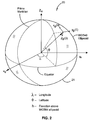
- FIG. 2 illustrates the definitions of e-frame and the g-frame
- FIG. 3 illustrates the definitions of the c-frame, h-frame, and b-frame
- FIG. 4 illustrates the control system on the swing axis for P&H Centurion controlled shovels
- FIG. 5 illustrates the characteristics of saturation type non-linearities including the describing function gain as a function of the input.
- FIG. 6 illustrates coordinate systems for P&H-class electric mining shovels
- FIG. 7 illustrates a P&H-class electric mining shovel in the right angle configuration for the purpose of defining the b-frame
- FIG. 8 illustrates a flow chart of the steps of the method of the preferred embodiment.
- the preferred embodiments provide an improved method 80 for determining the global spatial pose of an electric mining shovel.
- the global spatial pose includes
- a basic characteristic in the operation of a mining shovel 1 and other similar excavators is that they maintain the location of the c-frame for many minutes at a time. That is to say, repositioning the machine using the crawler tracks 2 is done infrequently and between moves the main activity is the back-and-forth swinging motion of the machine house 3 as the excavator sequentially digs material and loads the material into haul trucks 4 .
- the preferred embodiment exploits such operational characteristics of mining shovels 1 to address the problem of determining the pose of the shovel.
- the preferred embodiment also exploits the combinations of several available complimentary sensor measurements, including
- the preferred embodiment presents a formulation of a recursive algorithm based on the extended Kalman filter that determines the global shovel pose using combinations of these measurements.
- Knowing shovel pose in real-time is useful for several purposes, which include
- FIGS. 2 and 3 The geometry relevant to the problem including the various coordinate frames are shown in FIGS. 2 and 3 .
- FIG. 2 there is shown the geometry frames for locating the earth frame (e-frame) and geodetic coordinate frame (g-frame) relative to the earth 21 .
- FIG. 3 illustrates the car body frame (c-frame), the house frame (h-frame) and the bucket frame (b-frame).
- the pose of the shovel bucket is computed in two stages.
- the objective in the first stage is to compute the location of the c-frame relative to the h-frame from the following measurements
- the objective in the second stage is, having found the location of the c-frame relative to the g-frame, to compute the location of the h-frame relative to the c-frame using the following measurements
- the objective in the third stage is to compute the location of the b-frame relative to the h-frame using the following measurements
- the measurements used at Stage 1 can provide rich information about the low frequency motions of the machine sufficient to accurately determine the position of the c-frame relative to the g-frame.
- the sensor measurements used at Stage 2 aim towards accurate determination of these motions. In this sense, the Stage 2 filter aims towards a higher bandwidth of estimation.
- the methodology for the calculation of Stages 1 and 2 is the extended Kalman filter (EKF), Gelb (1974),
- z k h ( x k ,u k ,k )+ v k , v k ⁇ N (0, R ) (1)
- f(x,u,t) is a vector-valued function describing the dynamics of the system that is used to propagate the current estimate of state and state covariance forward in time based on measurement of the operator command reference, so it can be combined with newly obtained measurement data.
- the vector-valued function h(x k ,u k ,k) expresses the measurements in terms of the state vector x and inputs u.
- the EKF requires linearization of f(x,u,t) and h(x k ,u k ,k) about the estimated state trajectory ⁇ circumflex over (x) ⁇ and the conversion of the linearized continuous dynamics to a discrete time form. It is desirable to use the following notation:
- Equations 1 The vectors w and v in Equations 1 are termed the process and measurement noise and are assumed to be generated by zero mean, Gaussian processes with covariances Q and R respectively.
- Equations 7 to 11 define the EKF algorithm which provides the best linear state estimator for a non-linear system measured by the minimum mean squared error.
- the superscripts ‘ ⁇ ’ and ‘+’ in Equations 7 to 11 indicate evaluation of quantities before and after a measurement has been made.
- the dynamic model used for propagation of shovel pose in Stages 1 and 2 includes, as a common element, a causal model relating operator joystick reference to swing motions within the vector-valued function f (x,u,t).
- the preferred embodiment of this model for Centurion enables P&H shovels is given below.
- P&H Centurion enabled electric mining shovels use an ABB DCS/DCF600 Multi-Drive controller to regulate motor speed, armature current and field current in each of the three DC motors.
- the controller is made up of four integral components; a PID or PI motor speed control loop, an armature current saturation limiter, a PI current control loop and an EMF-field current regulator.
- the swing drive uses a combination of torque control and bang-bang speed control, where by the swing joystick position generates a piecewise speed reference and an armature current saturation limit.
- a schematic of the swing drive model is shown in FIG. 4 .
- the difference between the reference and actual swing motor speed feeds the Proportional-Integral-Derivative (PID) speed controller 41 incorporating derivative filtering.
- the output of the speed controller is scaled 42 into a reference armature current that is limited proportionally according to the amplitude of the swing joystick reference.
- the error between the limited current reference and the actual armature current feeds into a PI current controller 43 that outputs an armature voltage to the swing motor.
- the swing motor has a constant field current with the DCF600 maintaining the field voltage at a steady level.
- a sinusoidal input describing function is used.
- the describing function which will be abbreviated to DF, was developed primarily for the study of limit cycles in non-linear dynamic systems, see Gelb and Vander Velde (1968), and Graham and McRuer (1961).
- the basic idea of the describing function approach is to replace each non-linear element in a dynamic system with a quasi-linear descriptor or describing function equivalent gain whose magnitude is a function of the input amplitude.
- FIG. 5 illustrates the effect of a saturating amplifier on a sine wave input.
- the output 51 is proportional to the input.
- the output 53 becomes “clipped” and can be expressed by a Fourier series 55 , where the terms b 3 sin 3 ⁇ t, b 5 sin 5 ⁇ t, etc, represent new frequencies generated by the non-linear saturation element.
- the DF approach to modelling this saturation assumes that the higher order terms in the saturated output are negligible.
- a DF equivalent gain for sinusoidal saturation thus takes the form
- b is the first or fundamental term of the output's Fourier series and A is the amplitude of the input.
- the input vector u contains the reference motor speeds ⁇ s d generated from the joystick signals, the static torque load on the motor due to gravitational effects T s and a coulomb friction disturbance input f s .
- the state vector x for each model, contains swing armature current I s , the swing motor speed ⁇ s , the swing motor position ⁇ s , and the integrals of the error in the speed and current controllers, ⁇ e ⁇ s , and ⁇ e I s .
- the swing drive model also contains the swing reference armature current prior to the saturation limit I s ref . This state arises from the derivative component in the swing I S motor speed controller.
- the full state space models for the swing drive is given by
- the describing function gains G s appears as an element in drive system and input matrices which is recalculated at each time step.
- the input to the current limiter is the swing reference armature current state I s ref .
- the swing armature current saturation limits can be determined from the swing joystick position.
- Stage 1 and Stage 2 models should contain so-called ‘shaping stages’ that accommodate bias in sensors and account for physical artefacts such as transmission backlash.
- Stage 2 model can also be implemented by the use of so-called Ornstein-Uhlenbeck stochastic process whose parameters may be determined from subsequent autocorrelation analysis.
- Eqn. 12 expresses the GPS measurement made in the g-frame in terms of the position of the shovel carbody (x c ,y c ,z c ) and the direction cosine matrices R c2g and R h2c , describing the 3D rotations between the c- and g-, and the h- and c-frames, respectively.
- These matrices can be calculated in a number of ways, e.g. Euler angles or quaternions.
- the parameters describing these matrices are states of the estimator.
- GPS measurements are based around an approximation of the Earth's surface in the form of a bi-axial ellipsoid.
- the dimensions of this ellipsoid are defined by one of several standards or datums.
- FIG. 2 shows the WGS84 ellipsoid approximation 20 of the earth in which the latitude, longitude and altitude of the GPS antenna are expressed.
- the methodology used to transform the sensor reading from the GPS receivers, measured in e-frame latitude, longitude, and altitude, into coordinates in the g-frame is as follows
- N 0 a 2 ( a 2 ⁇ cos 2 ⁇ ⁇ 0 + b 2 ⁇ sin 2 ⁇ ⁇ 0 ) 1 2 ( 13 )
- the pitch and roll inclinations of the machine house are determined as the angle between unit vectors in the x h - and y h -axes and the (x g , y g ) plane.
- Raw inclinometer measurements may be improved by factoring away accelerations of the sensor.
- the acceleration of the IMU will be measured as the global acceleration of its location in the machine house, (x i ,y i ,z i ), rotated to be aligned with the orthogonal sensor axes.
- a i d 2 d t 2 ⁇ ( ( x c , y c , z c ) T + R h ⁇ ⁇ 2 ⁇ ⁇ c ⁇ R c ⁇ ⁇ 2 ⁇ ⁇ g ⁇ ( x i , y i , z i ) T ) ( 22 )
- the g-frame is assumed to be non-accelerating and non-rotating.
- the angular velocity of the IMU will be measured as the global angular velocity of the machine house, rotated to be aligned with the orthogonal sensor axes.
- the measured angular velocities about the RPY axes are
- the Stage 3 calculations are dependent on the machine in question. In the preferred embodiment the calculations have been carried out for a P&H-class mining shovels
- FIG. 6 shows the parameters (lengths and angles) used to describe the geometry of P&H-class electric mining shovels and the coordinate frames used to describe relative positions of major moving assemblies of these machines. Lengths labeled l and angles labeled ⁇ are fixed by design; length labeled d and angles labeled ⁇ vary under machine motion. This geometry is needed to determine the location of the bucket relative to the h-frame.
- the c-frame is denoted O c x c y c z c ;
- the h-frame is denote O h x h y h z h and is embedded in the machine house;
- the O b x b y b z b b-frame in the dipper are in the sagittal plane of the machine house, that is the plane parallel to the plane of projection shown in FIG. 6 containing the swing axis.
- the y-axes of all frames are normal to this plane.
- D i -> j ( R i -> j t i -> j 0 1 )
- R i ⁇ j is a 3 ⁇ 3 rotation matrix
- t i ⁇ j is a 3-dimensional translation vector.
- the origin of the c-frame is located at the interface between the upper surface of the tracks and the underside surface of the machine house.
- the z c -axis collinear with the swing axis.
- the x c -axis points in the direction of forward travel of the crawler tracks, and the y c -axis completes a right-handed trihedral coordinate frame.
- D h ⁇ m ( cos ⁇ ⁇ ⁇ 2 0 - sin ⁇ ⁇ ⁇ 2 l 1 ⁇ cos ⁇ ⁇ ⁇ 1 0 1 0 0 sin ⁇ ⁇ ⁇ 2 0 cos ⁇ ⁇ ⁇ 2 l 1 ⁇ sin ⁇ ⁇ ⁇ 1 0 0 0 1 ) , where design parameters l 1 and ⁇ 1 are as shown in FIG. 6 .
- the origin O b of O b x b y b z b is located as follows.
- the saddle angle ( ⁇ 2 ) is set equal to 90 degrees so that the handle is horizontal.
- the origin O b is located at the intersection of the pitch-line of the handle-rack and the hoist rope;
- z b is set to be collinear with the axis of the hoist rope;
- x b is set parallel to the pitch-line of the handle-rack.
- axis x m is orthogonal to axis x b .
- the displacement matrix describing the rigid body displacement D m ⁇ b is given by
- the swing angle, ⁇ 1 , the pivot angle, ⁇ 2 , and the crowd extension, d 3 parameterize the displacement and rotation of the body fixed frames relative to the world frame.
- the values of ⁇ determine ⁇ and vice versa. These mappings are not bijective. However, within the physical working range of these variables their correspondence is one-to-one. Note that the specification of either ⁇ or ⁇ determines the inclination of the hoist rope, a seventh variable, labeled ⁇ 5 in FIG. 6 .
- Equation 25 can be used to relate d 5 and d h ,
- ⁇ 2 ⁇ ( ⁇ , ⁇ , ⁇ 5 ) [ l 1 ⁇ cos ⁇ ⁇ ⁇ 1 + l 2 ⁇ cos ⁇ ⁇ ⁇ 2 + d 3 ⁇ sin ⁇ ⁇ ⁇ 2 + l 4 ⁇ cos ⁇ ⁇ ⁇ 2 + [ ⁇ h G h + l 6 ⁇ ( ⁇ 5 - ⁇ 2 ) ] ⁇ cos ⁇ ⁇ ⁇ 5 - l 6 ⁇ sin ⁇ ⁇ ⁇ 5 - l 7 ⁇ cos ⁇ ⁇ ⁇ 7 l 1 ⁇ sin ⁇ ⁇ ⁇ 1 + l 2 ⁇ sin ⁇ ⁇ ⁇ 2 - d 3 ⁇ cos ⁇ ⁇ ⁇ 2 + l 4 ⁇ sin ⁇ ⁇ ⁇ 2 + [ ⁇ h G h + l 6 ⁇ ( ⁇ 5 - ⁇ 2 ) ] ⁇ sin ⁇ ⁇ ⁇ 5 + l 6 ⁇ cos ⁇
- ⁇ ⁇ ( ⁇ , ⁇ , ⁇ 5 ) [ G s ⁇ ⁇ 1 - ⁇ s G c ⁇ d 3 - ⁇ c l 1 ⁇ cos ⁇ ⁇ ⁇ 1 + l 2 ⁇ cos ⁇ ⁇ ⁇ 2 + d 3 ⁇ sin ⁇ ⁇ ⁇ 2 + l 4 ⁇ cos ⁇ ⁇ ⁇ 2 + [ ⁇ h G h + l 6 ⁇ ( ⁇ 5 - ⁇ 2 ) ] ⁇ cos ⁇ ⁇ ⁇ 5 - l 6 ⁇ sin ⁇ ⁇ ⁇ 5 - l 7 ⁇ cos ⁇ ⁇ ⁇ 7 l 1 ⁇ sin ⁇ ⁇ ⁇ 1 + l 2 ⁇ sin ⁇ ⁇ ⁇ 2 - d 3 ⁇ cos ⁇ ⁇ ⁇ 2 + l 4 ⁇ sin ⁇ ⁇ ⁇ 2 + [ ⁇ h G h + l 6 ⁇ ( ⁇ 5 d 3
- the kinematic tracking problem is to determine the values of ⁇ and ⁇ 5 given ⁇ or to determine ⁇ and ⁇ 5 given ⁇ .
- ⁇ F ( ⁇ 1 , ⁇ 2 , ⁇ 3 , ⁇ 5 )
- ⁇ F ( ⁇ s , ⁇ c , ⁇ h )
- ⁇ l ( ⁇ 1 , ⁇ 2 , ⁇ 3 )
- ⁇ l ( ⁇ s , ⁇ c , ⁇ h , ⁇ 5 )
- the algorithm below gives an algorithm for kinematic tracking for P&H-class shovels.
- the algorithm takes the current motor positions, ⁇ F k and uses Eqns. 31 and 32 to find the new values of ⁇ F k consistent with the constraint equations.
- the algorithm requires a good initial values ⁇ F 0 . In practice this can be achieved by initializing from a well defined configuration such as provided in FIG. 6 where the forward kinematics can be explicitly solved using trigonometry.
- Algorithm 3 Forward kinematic tracking using Newton's method input: Current motor position ⁇ F k . output: Values of configuration variables ⁇ F k consistent with the constraint equations. priors: Previous motor and configuration variables: ⁇ F k-1 , ⁇ F k-1 .
- the preferred embodiments provide an accurate method for maintaining a close approximation of the shovel position at all times.
Abstract
Description
-
- The designation of an Earth-Centred-Earth-Fixed (ECEF) frame or
e-frame 81; - The identification of a local geodetic coordinate frame (g-frame) defined as a set of Cartesian coordinate axes in the e-frame and aligned, for example, with the North, East and Down convention. The origin of this frame is somewhere near to the mining shovel, typically within the mine property at which the machine is located 82;
- The designation of a set of Cartesian coordinate axes fixed to the carbody or under-carriage of the
mining shovel 83. The Cartesian frame defined by these axes is to be known as the c-frame; - The determination of the location (position and orientation) of the c-frame within the g-
frame 84; - The designation of a set of Cartesian coordinate axes fixed to the machine house of the mining shovel. The Cartesian frame defined by these axes is to be known as the h-
frame 85; - The determination of the location (position and orientation) of the h-frame within the c-
frame 86; - The designation of a set of Cartesian coordinate axes fixed to the shovel handle and dipper (bucket)
assembly 87. The Cartesian frame defined by these axes is to be known as the b-frame; - The determination of the location (position and orientation) of the b-frame within the h-
frame 88.
Collectively these coordinate definitions enable the location of the bucket to be established in global coordinate frame.
- The designation of an Earth-Centred-Earth-Fixed (ECEF) frame or
-
- Real-Time Kinematic Global Position System (RTK-GPS) measurements in the e-frame of the position of one or more identified points fixed to the h-frame;
- Inertial measurements made of three orthogonal accelerations and three orthogonal angular rates of the h-frame relative to the g-frame;
- Inclinometer measurements of the pitch and roll of the h-frame relative to the g-frame;
- Speed and position measurements of the three primary motion actuators, namely the swing, crowd, and hoist motors;
- Voltage and current measurements from the three primary motion actuators, namely the swing, crowd, and hoist motors;
- Reference values set by the shovel operator, usually through joysticks, that are inputs to the control systems of the three primary motion actuators, namely the swing, crowd and hoist motors.
- 1. An application for which commercial systems already exist uses knowledge of the position of the dipper during digging, relative to the resource map, as a means for allowing the operator to distinguish ore from waste;
- 2. An application of emerging importance is for automation of mining equipment where an important problem requiring solution is controlling interactions with other equipment such as haul trucks. If such equipment units are equipped with similar pose estimation capabilities, the relative pose between equipment can be determined;
- 3. Knowledge of shovel pose is also needed for proper spatial registration of data from scanning range sensors, e.g. laser scanners and mm-wave radar as might be used for ranging in automation systems and for the development of local digital terrain maps.
-
- the positions in the g-frame of n RTK-GPS receivers;
- the apparent orientation of the zh-axis relative to the zg-axis, as measured by a dual-axis inclinometer fixed in the h-frame;
- the rotation of the h-frame about the zc-axis;
- the angular velocity of the swing motor;
- the armature current and armature voltage of the swing motor;
- the operator command references from joysticks.
These quantities define a measurement vector z and an input vector u.
-
- the positions in the g-frame of n RTK-GPS receivers;
- measurements of the angular rates and linear accelerations in three orthogonal directions of a point fixed in the h-frame but measured in an inertial frame which is instantaneously aligned with the orthogonal sensor axes;
- the rotation of the h-frame about the zc-axis;
- the angular velocity of the swing motor;
- the armature current and armature voltage of the swing motor;
- the operator command references from joysticks.
These quantities define a second measurement vector z and a second input vector u.
-
- Position of the hoist motor
- Position of the crowd motor
and a kinematic model of the digging assembly. TheStage 3 calculations are kinematic and compute the location of the b-frame relative to the h-frame.
-
- Immediately after the machine has completed any propel motion and entered normal digging activity, characterized by repetitive to-and-fro swinging, the first stage calculations are run for a sufficient time to obtain a converged estimate for the location of the c-frame relative to the g-frame. The location of the g-frame with respect to the e-frame is assumed to be a priori known;
- After convergence has been obtained at
Stage 1, the second and then third stages of calculations are initiated and made at regular time steps to determine the position of the h-frame relative to the c-frame and the b-frame relative to the h-frame; - When the operator next propels the machine, calculations cease until completion of the propelling motion whereupon the first stage calculations are again executed to find a new converged estimate for the location of the c-frame relative to the g-frame. The calculations then move to
Stage 2, and so forth.
{dot over (x)}=f(x,u,t)+w, w˜N(0,Q)
z k =h(x k ,u k ,k)+v k , v k ˜N(0,R) (1)
where f(x,u,t) is a vector-valued function describing the dynamics of the system that is used to propagate the current estimate of state and state covariance forward in time based on measurement of the operator command reference, so it can be combined with newly obtained measurement data. The vector-valued function h(xk,uk,k) expresses the measurements in terms of the state vector x and inputs u.
where Δt is the measurement update rate and
xk+1 −=F{circumflex over (x)}k + (7)
2. State covariance propagation
P k+1 − =FP k + +P k + F T +Q (8)
3. Calculation of the Kalman gain
K k+1 =P k+1 − ∇h k+1 T(∇h k+1 P k+1 − ∇Vh k+1 T +R)−1 (9)
4. State estimate update
{circumflex over (x)} k+1 + ={circumflex over (x)} k+1 − +K k+1(z k+1 −h({circumflex over (x)} k+1 − ,k)) (10)
5. Error covariance update at time step k
P k+1 +=(I−K k+1 ∇h k+1)P k+1 − (11)
where b, is the first or fundamental term of the output's Fourier series and A is the amplitude of the input.
{dot over (x)}=Ax+Bu.
z gps(x c ,y c ,z c)T +R c2g R h2c(x a ,y a ,z a)T (12)
-
- The first stage is to convert the measurements into Cartesian coordinates with the origin at the centre of the Earth, with the x-axis defined at the longitude value of 0° (as can be seen above in
FIG. 2 ). - Vanicek (1986) defines that for any point, p0 on the ellipsoid approximation:
p0=N0 cos φ0 - Where N0 is the distance from the centre of the ellipsoid, and φ0 is the angle from the xe-ye plane (the latitude at point p0). The distance from the centre of the ellipsoid is defined as:
- The first stage is to convert the measurements into Cartesian coordinates with the origin at the centre of the Earth, with the x-axis defined at the longitude value of 0° (as can be seen above in
-
- These equations can be re-arranged to give the position vector r0 G, of the point p0, in global Cartesian coordinates:
-
- Where λ0 is the longitude at the point p0.
- In order to transform this global position into a local coordinate frame, a suitable local frame must first be defined. We define a set of axes centred at the point p0 such that the y-axis is tangential to the surface of the ellipsoid, and points in the direction that would appear to face North to an observer standing at p0. If we define this direction as “Apparent North”, then “Apparent East” is the vector which is tangential to the ellipsoid's surface, and orthogonal to both the vector r0 G and the vector Apparent North. This can then define a suitable local coordinate frame, with the y-axis aligned with Apparent North, the x-axis aligned with Apparent East and the z-axis representing the height above the surface of the ellipsoid. This formulation holds for any point p0 such that λ0≠±90°. If λ0=±90, the direction of the x- and y-axes is arbitrary as long as they are orthogonal and form a plane which is tangential to the surface of the ellipsoid.
- The local x-axis (apparent East) can be thought to have a latitude (relative to p0) of zero. If we represent this axis as the unit vector of vector ra, we can arbitrarily set ya to one, and use Equation 14 to give:
-
- The local y-axis (apparent North) can then be found by the requirement of being orthogonal to both the local x and z-axes:
r b =r G ×r a (16) - Finally, the transformation matrix from global to local coordinates can be defined as:
- The local y-axis (apparent North) can then be found by the requirement of being orthogonal to both the local x and z-axes:
-
- This gives the final transformation from global to local coordinates for a point pn as:
p n local =T·(p n global −r 0 G). (18)
- This gives the final transformation from global to local coordinates for a point pn as:
α=sin−1(sin θc sin φc) (19)
β=sin−1(sin θc cos φc) (20)
Raw inclinometer measurements may be improved by factoring away accelerations of the sensor.
zacc=Rg2cRc2hai (21)
Where the acceleration of the IMU in the g-frame is found from
The g-frame is assumed to be non-accelerating and non-rotating.
p′=D0→3p.
The structure of Di→j is
where Ri→j is a 3×3 rotation matrix and ti→j is a 3-dimensional translation vector. Four-by-four homogeneous transformation matrices commute according to
Di→k=Di→jDj→k.
Frame Omxmymzm is fixed to the saddle with O2 at the center of rotation of the saddle. When θ2 is equal to 0, the coordinate directions of Omxmymzm are parallel to those of Ohxhyhzh. The displacement matrix describing the rigid body displacement from Frame h to Frame n is given by
where design parameters l1 and φ1 are as shown in
θ=(θ1,θ2,d3)T.
ψ=(θs,θc,θh)T.
The values of θ determine ψ and vice versa. These mappings are not bijective. However, within the physical working range of these variables their correspondence is one-to-one. Note that the specification of either θ or ψ determines the inclination of the hoist rope, a seventh variable, labeled θ5 in
where Gs is the transmission ratio of the swing drive and Gc is the transmission ratio of the crowd drive.
0=ζ(θ,ψ,θ5)=z 1 +z 2 +z 3 +z 4 +z 5 −z 6 −z 7,
which can be expanded to give,
0=ζ(θ,ψ,θ5)=l 1 e iφ
where the variables li, di, θi and φi are as defined in
Eqn. 24 can be written as,
ζ(θ,ψ,θ5)=l 1 e iφ
where Gh is the hoist transmission ratio. The above expression and Equation 25 can be used to relate d5 and dh,
The last term on the right hand side of Eqn. 27 accounts for the angle of wrap of the hoist rope around the sheave. Substituting Eqn. 27 into Eqn. 26 gives
Note that use has been made of the following trigonometric relationships in arriving at Eqn. 29,
Concatenating Eqns. 23a and 29 gives
Kinematic Tracking by Newton-Raphson
θF=(θ1,θ2,θ3,θ5)
ψF=(θs,θc,θh)
when working in the domain of the forward kinematic tracking problem and
θl=(θ1,θ2,θ3)
ψl=(θs,θc,θh,θ5)
The objective is to find a valid configuration, i.e. Γ(θF+ΔθF,ψF+ΔψF)=0. It follows that
This leads to the iteration equation
| Algorithm 3: Forward kinematic tracking using Newton's method |
| input: Current motor position ψF k. |
| output: Values of configuration variables θF k consistent with the constraint equations. |
| priors: Previous motor and configuration variables: θF k-1, ψF k-1. |
| Initialization: |
| Δ ψF k = ψF k − ψF k-1 |
| θF k = θF k-1 |
| ΓF = Γ(θF k, ψF k) |
| Iterate until converged: |
|
|
| θF k = θF k + ΔθF k |
| ΓF = Γ(θF k, ψF k) |
Claims (12)
Applications Claiming Priority (3)
| Application Number | Priority Date | Filing Date | Title |
|---|---|---|---|
| AU2008900081A AU2008900081A0 (en) | 2008-01-08 | A realtime method for determining the spatial pose of electric mining shovels | |
| AU2008900081 | 2008-01-08 | ||
| PCT/AU2009/000019 WO2009086601A1 (en) | 2008-01-08 | 2009-01-07 | A real time method for determining the spatial pose of electric mining shovels |
Publications (2)
| Publication Number | Publication Date |
|---|---|
| US20100283675A1 US20100283675A1 (en) | 2010-11-11 |
| US8571762B2 true US8571762B2 (en) | 2013-10-29 |
Family
ID=40852710
Family Applications (1)
| Application Number | Title | Priority Date | Filing Date |
|---|---|---|---|
| US12/812,186 Active 2030-01-06 US8571762B2 (en) | 2008-01-08 | 2009-01-07 | Real time method for determining the spatial pose of electronic mining shovels |
Country Status (7)
| Country | Link |
|---|---|
| US (1) | US8571762B2 (en) |
| CN (1) | CN101970763B (en) |
| AU (1) | AU2009203898B2 (en) |
| CA (1) | CA2711550C (en) |
| CL (1) | CL2009000010A1 (en) |
| WO (1) | WO2009086601A1 (en) |
| ZA (1) | ZA201005145B (en) |
Cited By (10)
| Publication number | Priority date | Publication date | Assignee | Title |
|---|---|---|---|---|
| US20130113556A1 (en) * | 2011-11-04 | 2013-05-09 | Rf Micro Devices, Inc. | Voltage, current, and saturation prevention |
| US20140207331A1 (en) * | 2012-02-10 | 2014-07-24 | Alexey Andreevich Kosarev | Estimation of the relative attitude and position between a vehicle body and an implement operably coupled to the vehicle body |
| US20140336883A1 (en) * | 2011-12-02 | 2014-11-13 | Caterpillar Sarl | Determining the relative orientation of members of an articulated work machine |
| US9115581B2 (en) | 2013-07-09 | 2015-08-25 | Harnischfeger Technologies, Inc. | System and method of vector drive control for a mining machine |
| US20160237655A1 (en) * | 2014-06-04 | 2016-08-18 | Komatsu Ltd. | Posture computing apparatus for work machine, work machine, and posture computation method for work machine |
| US20170084089A1 (en) * | 2015-09-23 | 2017-03-23 | Caterpillar Inc. | Method and system for collecting machine operation data using a mobile device |
| US9792739B2 (en) * | 2015-12-10 | 2017-10-17 | Caterpillar Inc. | Operation monitoring system for machine and method thereof |
| US10120369B2 (en) | 2015-01-06 | 2018-11-06 | Joy Global Surface Mining Inc | Controlling a digging attachment along a path or trajectory |
| US11085170B2 (en) | 2018-05-01 | 2021-08-10 | Rodradar Ltd. | Method of operating a machine comprising an implement |
| US11939748B2 (en) | 2021-03-29 | 2024-03-26 | Joy Global Surface Mining Inc | Virtual track model for a mining machine |
Families Citing this family (43)
| Publication number | Priority date | Publication date | Assignee | Title |
|---|---|---|---|---|
| JP4840442B2 (en) * | 2006-02-15 | 2011-12-21 | 株式会社安川電機 | Suspended load stabilization device |
| US8798874B2 (en) * | 2010-10-20 | 2014-08-05 | Harnischfeger Technologies, Inc. | System for limiting contact between a dipper and a shovel boom |
| US8527158B2 (en) * | 2010-11-18 | 2013-09-03 | Caterpillar Inc. | Control system for a machine |
| AU2012202213B2 (en) | 2011-04-14 | 2014-11-27 | Joy Global Surface Mining Inc | Swing automation for rope shovel |
| WO2012148437A1 (en) | 2011-04-29 | 2012-11-01 | Harnischfeger Technologies, Inc. | Controlling a digging operation of an industrial machine |
| US8788245B2 (en) | 2011-07-15 | 2014-07-22 | Harnischfeger Technologies, Inc. | Systems and methods for actively biasing a loadpin |
| US8886493B2 (en) | 2011-11-01 | 2014-11-11 | Harnischfeger Technologies, Inc. | Determining dipper geometry |
| CN104066898B (en) * | 2012-01-02 | 2016-06-01 | 沃尔沃建造设备有限公司 | For controlling the mechanical method dumping operation of constructing |
| US9037359B2 (en) | 2012-01-31 | 2015-05-19 | Harnischfeger Technologies, Inc. | System and method for determining saddle block shimming gap of an industrial machine |
| US9206587B2 (en) * | 2012-03-16 | 2015-12-08 | Harnischfeger Technologies, Inc. | Automated control of dipper swing for a shovel |
| CA2813280A1 (en) * | 2012-04-20 | 2013-10-20 | Harnischfeger Technologies, Inc. | Fluid conveyance system for earthmoving machine |
| US9593460B2 (en) * | 2012-09-21 | 2017-03-14 | Harnischfeger Technologies, Inc. | Fluid conveyance system for industrial machine |
| AU2013245549B2 (en) | 2012-10-19 | 2017-05-25 | Joy Global Surface Mining Inc | Conduit support system |
| CN102912817A (en) * | 2012-11-19 | 2013-02-06 | 中联重科股份有限公司渭南分公司 | Excavator as well as control method and control device thereof |
| CN104915571B (en) * | 2015-06-26 | 2017-09-12 | 郑州北斗七星通讯科技有限公司 | A kind of forklift loads the recognition methods of behavior with material relevance |
| JP6779759B2 (en) * | 2016-11-21 | 2020-11-04 | 日立建機株式会社 | Construction machinery |
| WO2019026169A1 (en) * | 2017-08-01 | 2019-02-07 | J Think株式会社 | Operation system for working machine |
| US10473790B2 (en) | 2017-11-17 | 2019-11-12 | Swift Navigation, Inc. | Systems and methods for distributed dense network processing of satellite positioning data |
| US10578747B2 (en) | 2017-12-14 | 2020-03-03 | Swift Navigation, Inc. | Systems and methods for reduced-outlier satellite positioning |
| US11885221B2 (en) * | 2018-02-27 | 2024-01-30 | Joy Global Surface Mining Inc | Shovel stabilizer appendage |
| US10900202B2 (en) * | 2018-05-14 | 2021-01-26 | Caterpillar Trimble Control Technologies Llc | Systems and methods for generating operational machine heading |
| CN110645978A (en) * | 2018-06-26 | 2020-01-03 | 北京自动化控制设备研究所 | High-precision positioning method of optical fiber inertial navigation for excavator |
| CN111137277A (en) * | 2018-11-05 | 2020-05-12 | 陕西汽车集团有限责任公司 | Method for setting automatic parking position of unmanned mining vehicle |
| CN109814561A (en) * | 2019-01-28 | 2019-05-28 | 中南大学 | Method, apparatus, system and storage medium are determined by mine pose |
| CN109778942B (en) * | 2019-03-12 | 2023-05-16 | 辽宁工程技术大学 | Strip mine electric shovel centering control system and method |
| CN109903383B (en) * | 2019-04-11 | 2020-11-10 | 中国矿业大学 | Method for accurately positioning coal mining machine in three-dimensional model of working face coal seam |
| CN110058281B (en) * | 2019-04-29 | 2021-09-17 | 湖南国科微电子股份有限公司 | Dynamic positioning method and device |
| CN114174850A (en) | 2019-05-01 | 2022-03-11 | 斯威夫特导航股份有限公司 | System and method for high integrity satellite positioning |
| EP4007928A4 (en) * | 2019-08-01 | 2023-12-20 | Swift Navigation, Inc. | System and method for gaussian process enhanced gnss corrections generation |
| US11821167B2 (en) * | 2019-09-05 | 2023-11-21 | Deere & Company | Excavator with improved movement sensing |
| CN110994119B (en) * | 2019-11-28 | 2022-03-01 | 成都智巡科技有限责任公司 | RTK antenna beta structure |
| US11230826B2 (en) * | 2020-01-24 | 2022-01-25 | Caterpillar Inc. | Noise based settling detection for an implement of a work machine |
| US11693411B2 (en) | 2020-02-27 | 2023-07-04 | Deere & Company | Machine dump body control using object detection |
| US11480690B2 (en) | 2020-06-09 | 2022-10-25 | Swift Navigation, Inc. | System and method for satellite positioning |
| CN111678476B (en) * | 2020-06-12 | 2021-09-17 | 西安中科微精光子制造科技有限公司 | Method for measuring direction and spatial position of rotation center of rotating shaft |
| US11378699B2 (en) | 2020-07-13 | 2022-07-05 | Swift Navigation, Inc. | System and method for determining GNSS positioning corrections |
| CN116324511A (en) | 2020-07-17 | 2023-06-23 | 斯威夫特导航股份有限公司 | System and method for providing GNSS corrections |
| WO2022133294A1 (en) | 2020-12-17 | 2022-06-23 | Swift Navigation, Inc. | System and method for fusing dead reckoning and gnss data streams |
| US11733397B2 (en) | 2021-07-24 | 2023-08-22 | Swift Navigation, Inc. | System and method for computing positioning protection levels |
| US11693120B2 (en) | 2021-08-09 | 2023-07-04 | Swift Navigation, Inc. | System and method for providing GNSS corrections |
| US11860287B2 (en) | 2022-03-01 | 2024-01-02 | Swift Navigation, Inc. | System and method for detecting outliers in GNSS observations |
| US11906640B2 (en) | 2022-03-01 | 2024-02-20 | Swift Navigation, Inc. | System and method for fusing sensor and satellite measurements for positioning determination |
| US11781286B1 (en) * | 2023-03-06 | 2023-10-10 | Charles Constancon | Method and system for calculating the mass of material in an excavating machine bucket |
Citations (12)
| Publication number | Priority date | Publication date | Assignee | Title |
|---|---|---|---|---|
| US5144317A (en) | 1990-04-07 | 1992-09-01 | Rheinbraun Aktiengesellschaft | Method of determining mining progress in open cast mining by means of satellite geodesy |
| DE4133392C1 (en) | 1991-10-09 | 1992-12-24 | Rheinbraun Ag, 5000 Koeln, De | Determining progress of mining material spreader - receiving signals from at least four satellites at end of tipping arm and at vehicle base and calculating actual geodetic positions and height of material tip |
| US5404661A (en) * | 1994-05-10 | 1995-04-11 | Caterpillar Inc. | Method and apparatus for determining the location of a work implement |
| US6191733B1 (en) * | 1999-06-01 | 2001-02-20 | Modular Mining Systems, Inc. | Two-antenna positioning system for surface-mine equipment |
| US6418364B1 (en) * | 2000-12-13 | 2002-07-09 | Caterpillar Inc. | Method for determining a position and heading of a work machine |
| US20050080559A1 (en) * | 2002-10-02 | 2005-04-14 | Hideto Ishibashi | Position measuring system for working machine |
| US20060230645A1 (en) * | 2005-04-15 | 2006-10-19 | Topcon Positioning Systems, Inc. | Method and apparatus for satellite positioning of earth-moving equipment |
| US20070185681A1 (en) * | 2006-02-08 | 2007-08-09 | Honeywell International Inc. | Mapping systems and methods |
| US20080097693A1 (en) * | 2006-10-19 | 2008-04-24 | Topcon Positioning Systems, Inc. | Gimbaled satellite positioning system antenna |
| US20090112472A1 (en) * | 2007-10-26 | 2009-04-30 | Deere & Company | Three Dimensional Feature Location From An Excavator |
| US20090187527A1 (en) * | 2006-04-20 | 2009-07-23 | Cmte Development Limited | Payload estimation system and method |
| US20110311342A1 (en) * | 2007-10-26 | 2011-12-22 | Deere And Company | Three dimensional feature location from an excavator |
Family Cites Families (2)
| Publication number | Priority date | Publication date | Assignee | Title |
|---|---|---|---|---|
| US6282477B1 (en) * | 2000-03-09 | 2001-08-28 | Caterpillar Inc. | Method and apparatus for displaying an object at an earthworking site |
| KR100847382B1 (en) * | 2004-08-10 | 2008-07-18 | 야마하 가부시키가이샤 | Azimuth data producing method, azimuth sensor unit and portable electronic device |
-
2009
- 2009-01-06 CL CL2009000010A patent/CL2009000010A1/en unknown
- 2009-01-07 WO PCT/AU2009/000019 patent/WO2009086601A1/en active Application Filing
- 2009-01-07 CA CA2711550A patent/CA2711550C/en active Active
- 2009-01-07 AU AU2009203898A patent/AU2009203898B2/en active Active
- 2009-01-07 CN CN2009801054006A patent/CN101970763B/en active Active
- 2009-01-07 US US12/812,186 patent/US8571762B2/en active Active
-
2010
- 2010-07-20 ZA ZA2010/05145A patent/ZA201005145B/en unknown
Patent Citations (12)
| Publication number | Priority date | Publication date | Assignee | Title |
|---|---|---|---|---|
| US5144317A (en) | 1990-04-07 | 1992-09-01 | Rheinbraun Aktiengesellschaft | Method of determining mining progress in open cast mining by means of satellite geodesy |
| DE4133392C1 (en) | 1991-10-09 | 1992-12-24 | Rheinbraun Ag, 5000 Koeln, De | Determining progress of mining material spreader - receiving signals from at least four satellites at end of tipping arm and at vehicle base and calculating actual geodetic positions and height of material tip |
| US5404661A (en) * | 1994-05-10 | 1995-04-11 | Caterpillar Inc. | Method and apparatus for determining the location of a work implement |
| US6191733B1 (en) * | 1999-06-01 | 2001-02-20 | Modular Mining Systems, Inc. | Two-antenna positioning system for surface-mine equipment |
| US6418364B1 (en) * | 2000-12-13 | 2002-07-09 | Caterpillar Inc. | Method for determining a position and heading of a work machine |
| US20050080559A1 (en) * | 2002-10-02 | 2005-04-14 | Hideto Ishibashi | Position measuring system for working machine |
| US20060230645A1 (en) * | 2005-04-15 | 2006-10-19 | Topcon Positioning Systems, Inc. | Method and apparatus for satellite positioning of earth-moving equipment |
| US20070185681A1 (en) * | 2006-02-08 | 2007-08-09 | Honeywell International Inc. | Mapping systems and methods |
| US20090187527A1 (en) * | 2006-04-20 | 2009-07-23 | Cmte Development Limited | Payload estimation system and method |
| US20080097693A1 (en) * | 2006-10-19 | 2008-04-24 | Topcon Positioning Systems, Inc. | Gimbaled satellite positioning system antenna |
| US20090112472A1 (en) * | 2007-10-26 | 2009-04-30 | Deere & Company | Three Dimensional Feature Location From An Excavator |
| US20110311342A1 (en) * | 2007-10-26 | 2011-12-22 | Deere And Company | Three dimensional feature location from an excavator |
Non-Patent Citations (1)
| Title |
|---|
| International Search Report/Written Opinion completed Feb. 10, 2009 for PCT/AU2009/000019. |
Cited By (15)
| Publication number | Priority date | Publication date | Assignee | Title |
|---|---|---|---|---|
| US8907726B2 (en) * | 2011-11-04 | 2014-12-09 | Rf Micro Devices, Inc. | Voltage, current, and saturation prevention |
| US20130113556A1 (en) * | 2011-11-04 | 2013-05-09 | Rf Micro Devices, Inc. | Voltage, current, and saturation prevention |
| US20140336883A1 (en) * | 2011-12-02 | 2014-11-13 | Caterpillar Sarl | Determining the relative orientation of members of an articulated work machine |
| US20140207331A1 (en) * | 2012-02-10 | 2014-07-24 | Alexey Andreevich Kosarev | Estimation of the relative attitude and position between a vehicle body and an implement operably coupled to the vehicle body |
| US9347205B2 (en) * | 2012-02-10 | 2016-05-24 | Topcon Positioning Systems, Inc. | Estimation of the relative attitude and position between a vehicle body and an implement operably coupled to the vehicle body |
| US9506221B2 (en) | 2013-07-09 | 2016-11-29 | Harnischfeger Technologies, Inc. | System and method of vector drive control for a mining machine |
| US9115581B2 (en) | 2013-07-09 | 2015-08-25 | Harnischfeger Technologies, Inc. | System and method of vector drive control for a mining machine |
| US20160237655A1 (en) * | 2014-06-04 | 2016-08-18 | Komatsu Ltd. | Posture computing apparatus for work machine, work machine, and posture computation method for work machine |
| US9598845B2 (en) * | 2014-06-04 | 2017-03-21 | Komatsu Ltd. | Posture computing apparatus for work machine, work machine, and posture computation method for work machine |
| US10120369B2 (en) | 2015-01-06 | 2018-11-06 | Joy Global Surface Mining Inc | Controlling a digging attachment along a path or trajectory |
| US20170084089A1 (en) * | 2015-09-23 | 2017-03-23 | Caterpillar Inc. | Method and system for collecting machine operation data using a mobile device |
| US10134204B2 (en) * | 2015-09-23 | 2018-11-20 | Caterpillar Inc. | Method and system for collecting machine operation data using a mobile device |
| US9792739B2 (en) * | 2015-12-10 | 2017-10-17 | Caterpillar Inc. | Operation monitoring system for machine and method thereof |
| US11085170B2 (en) | 2018-05-01 | 2021-08-10 | Rodradar Ltd. | Method of operating a machine comprising an implement |
| US11939748B2 (en) | 2021-03-29 | 2024-03-26 | Joy Global Surface Mining Inc | Virtual track model for a mining machine |
Also Published As
| Publication number | Publication date |
|---|---|
| CA2711550C (en) | 2016-06-07 |
| CA2711550A1 (en) | 2009-07-16 |
| AU2009203898B2 (en) | 2014-07-17 |
| AU2009203898A1 (en) | 2009-07-16 |
| CL2009000010A1 (en) | 2010-05-07 |
| WO2009086601A1 (en) | 2009-07-16 |
| CN101970763A (en) | 2011-02-09 |
| CN101970763B (en) | 2012-08-08 |
| US20100283675A1 (en) | 2010-11-11 |
| ZA201005145B (en) | 2013-12-23 |
Similar Documents
| Publication | Publication Date | Title |
|---|---|---|
| US8571762B2 (en) | Real time method for determining the spatial pose of electronic mining shovels | |
| US10704233B2 (en) | Dynamic motion compensation | |
| US10521703B2 (en) | System and method for controlling machine pose using sensor fusion | |
| US10401176B2 (en) | System and method for determining machine state using sensor fusion | |
| US10253476B2 (en) | Excavator limb length determination using a laser distance meter | |
| US10459462B2 (en) | Sensor fusion feedback for controlling fluid pressures in a machine | |
| US10724842B2 (en) | Relative angle estimation using inertial measurement units | |
| US9976279B2 (en) | Excavating implement heading control | |
| AU2018311580B2 (en) | Determining yaw and center-of-rotation of a rotating platform using a single position sensor | |
| US9145144B2 (en) | Inclination detection systems and methods | |
| US9816249B2 (en) | Excavating implement heading control | |
| US10371522B2 (en) | Iterative estimation of centripetal accelerations of inertial measurement units in kinematic chains | |
| CN117616178A (en) | IMU-based system for vertical shaft joint angle estimation of swing boom excavators | |
| Mononen et al. | Blade Control for Surface Profile Tracking by Heavy-Duty Bulldozers | |
| KR20220157732A (en) | Method for state estimation of construction machinary |
Legal Events
| Date | Code | Title | Description |
|---|---|---|---|
| AS | Assignment |
Owner name: CMTE DEVELOPMENT LIMITED, AUSTRALIA Free format text: ASSIGNMENT OF ASSIGNORS INTEREST;ASSIGNORS:MCAREE, PETER ROSS;REID, ANTHONY WALTON;SIGNING DATES FROM 20090316 TO 20090414;REEL/FRAME:024717/0793 Owner name: EZYMINE PTY LIMITED, AUSTRALIA Free format text: ASSIGNMENT OF ASSIGNORS INTEREST;ASSIGNOR:CMTE DEVELOPMENT LIMITED;REEL/FRAME:024717/0838 Effective date: 20091019 |
|
| STCF | Information on status: patent grant |
Free format text: PATENTED CASE |
|
| CC | Certificate of correction | ||
| FPAY | Fee payment |
Year of fee payment: 4 |
|
| MAFP | Maintenance fee payment |
Free format text: PAYMENT OF MAINTENANCE FEE, 8TH YEAR, LARGE ENTITY (ORIGINAL EVENT CODE: M1552); ENTITY STATUS OF PATENT OWNER: LARGE ENTITY Year of fee payment: 8 |