US8570401B2 - Image combining apparatus, image combining method and program product - Google Patents
Image combining apparatus, image combining method and program product Download PDFInfo
- Publication number
- US8570401B2 US8570401B2 US13/178,905 US201113178905A US8570401B2 US 8570401 B2 US8570401 B2 US 8570401B2 US 201113178905 A US201113178905 A US 201113178905A US 8570401 B2 US8570401 B2 US 8570401B2
- Authority
- US
- United States
- Prior art keywords
- image data
- combining
- image
- luminance component
- color
- Prior art date
- Legal status (The legal status is an assumption and is not a legal conclusion. Google has not performed a legal analysis and makes no representation as to the accuracy of the status listed.)
- Active, expires
Links
Images


Classifications
-
- H—ELECTRICITY
- H04—ELECTRIC COMMUNICATION TECHNIQUE
- H04N—PICTORIAL COMMUNICATION, e.g. TELEVISION
- H04N1/00—Scanning, transmission or reproduction of documents or the like, e.g. facsimile transmission; Details thereof
- H04N1/46—Colour picture communication systems
-
- H—ELECTRICITY
- H04—ELECTRIC COMMUNICATION TECHNIQUE
- H04N—PICTORIAL COMMUNICATION, e.g. TELEVISION
- H04N23/00—Cameras or camera modules comprising electronic image sensors; Control thereof
- H04N23/70—Circuitry for compensating brightness variation in the scene
- H04N23/741—Circuitry for compensating brightness variation in the scene by increasing the dynamic range of the image compared to the dynamic range of the electronic image sensors
-
- G—PHYSICS
- G06—COMPUTING; CALCULATING OR COUNTING
- G06T—IMAGE DATA PROCESSING OR GENERATION, IN GENERAL
- G06T5/00—Image enhancement or restoration
-
- H—ELECTRICITY
- H04—ELECTRIC COMMUNICATION TECHNIQUE
- H04N—PICTORIAL COMMUNICATION, e.g. TELEVISION
- H04N9/00—Details of colour television systems
- H04N9/64—Circuits for processing colour signals
- H04N9/73—Colour balance circuits, e.g. white balance circuits or colour temperature control
-
- H—ELECTRICITY
- H04—ELECTRIC COMMUNICATION TECHNIQUE
- H04N—PICTORIAL COMMUNICATION, e.g. TELEVISION
- H04N5/00—Details of television systems
- H04N5/76—Television signal recording
- H04N5/765—Interface circuits between an apparatus for recording and another apparatus
- H04N5/77—Interface circuits between an apparatus for recording and another apparatus between a recording apparatus and a television camera
- H04N5/772—Interface circuits between an apparatus for recording and another apparatus between a recording apparatus and a television camera the recording apparatus and the television camera being placed in the same enclosure
Definitions
- the present disclosure relates to the subject matters contained in Japanese Patent Application No. 2010-157280 filed on Jul. 9, 2010 and Japanese Patent Application No. 2011-044529 filed on Mar. 1, 2011, which are incorporated herein by reference in its entirety.
- the present invention relates to a technique for generating a composite image with a dynamic range widened by use of a plurality of images continuously shot in various exposure conditions.
- a photographic image has been recently subjected to various kinds of image processing for dramatic impact in viewing the image.
- HDR High Dynamic Range
- An object of the invention is to provide an HDR image with less whiteout or shadowing and saturation of which is appropriately adjusted.
- an image combining apparatus including: a separator configured to separate each of a plurality of image data captured in different exposure conditions and at the same field angle into a plurality of first image data and a plurality of second image data, each of the plurality of first image data composed of luminance components specified in a certain color space, each of the plurality of second image data composed of other components than the luminance components; a first combining unit configured to combine, by using certain combining rates, the separated plurality of first image data that are different in exposure condition; and a second combining unit configured to combine, by using the certain combining rates used for combining by the first combining unit, the plurality of second image data that are different in exposure condition.
- an image combining method including: separating each of a plurality of image data captured in different exposure conditions and at the same field angle into a plurality of first image data and a plurality of second image data, each of the plurality of first image data composed of luminance components specified in a certain color space, each of the plurality of second image data composed of other components than the luminance components; combining, by using certain combining rates, the separated plurality of first image data that are different in exposure condition; and combining, by using the certain combining rates, the plurality of second image data that are different in exposure condition.
- a program product for causing a computer to serve as: a separator configured to separate each of a plurality of image data captured in different exposure conditions and at the same field angle into a plurality of first image data and a plurality of second image data, each of the plurality of first image data composed of luminance components specified in a certain color space, each of the plurality of second image data composed of other components than the luminance components; a first combining unit configured to combine, by using certain combining rates, the separated plurality of first image data that are different in exposure condition; and a second combining unit configured to combine, by using the certain combining rates used for combining by the first combining unit, the plurality of second image data that are different in exposure condition.
- FIG. 1 is a circuit diagram of an image capturing apparatus according to an exemplary embodiment of the invention
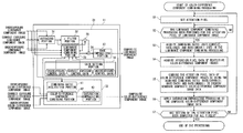
- FIG. 2 is a functional block diagram showing functional configuration with respect to a function for executing a combining processing in the embodiment
- FIG. 3 is a view showing an example of a combining rate setting table
- FIG. 4A shows an example of an underexposure luminance component image
- FIG. 4B shows a correct exposure luminance component image captured at the same field angle as the field angle of the image shown in FIG. 4A by continuous shooting;
- FIG. 4C shows an overexposure luminance component image captured at the same field angle as the field angles of the images shown in FIGS. 4A and 4B by continuous shooting;
- FIG. 4D shows an average luminance component image
- FIG. 4E shows a smoothed average luminance component image
- FIG. 4F shows a composite luminance component image
- FIG. 5 is a view showing an example of a combining rate table in which control gain is reflected
- FIGS. 6A and 6B are views showing a brightness adjusting effect based on the control gain
- FIGS. 7A to 7C are views showing a contrast emphasizing effect
- FIG. 8 is a flow chart showing an example of a flow of color-difference component combining processing performed by a color-difference component combining section in FIG. 2 ;
- FIG. 9 is a block diagram showing hardware configuration of an image processing apparatus according to the embodiment.
- FIG. 1 is a circuit diagram of an image capturing apparatus equipped with an image processing apparatus according to an exemplary embodiment of the invention.
- the image capturing apparatus has an image capturing portion 1 , a drive control portion 2 , a CDS/ADC 3 , a key input portion 4 , a display portion 5 , an image recording portion 6 , a program memory 7 , a RAM 8 , a control portion 9 , and an image processing portion 10 .
- the key input portion 4 has a shutter key 41 for detecting a photographer's recording instruction.
- the image processing portion 10 has an image combining portion 11 corresponding to the characteristic configuration of the invention. These are connected to one another through a bus line.
- the image capturing portion 1 includes an image sensor such as a CMOS, an RGB color filter provided on the image sensor, and a driver which holds light intensity as stored electric charges for a certain time under control of the drive control portion 2 and outputs these electric charges as an analog captured image signal to the CDS/ADC 3 .
- an image sensor such as a CMOS, an RGB color filter provided on the image sensor, and a driver which holds light intensity as stored electric charges for a certain time under control of the drive control portion 2 and outputs these electric charges as an analog captured image signal to the CDS/ADC 3 .
- the image capturing portion 1 detects a photographer's shooting instruction via the shutter key 41 , the control portion 9 and the drive control portion 2 to thereby acquire a plurality of images (color images) including underexposure image data, correct exposure image data and overexposure image data in various exposure conditions (shutter speeds or aperture values).
- the CDS/ADC 3 is a circuit into which an analog captured image signal is inputted in accordance with an optical image of a subject outputted from the image capturing portion 1 .
- the CDS/ADC 3 includes a CDS which holds the input captured image signal, a gain control amplifier (AGC) which amplifies the captured image signal, and an A/D converter (ADC) which converts the amplified captured image signal into a digital captured image signal.
- AGC gain control amplifier
- ADC A/D converter
- control regarding adjustment of the gain control amplifier is performed based on an instruction given from the drive control portion 2 . Accordingly, even when a plurality of images are acquired in spite of the same exposure condition, it is possible to generate images in different conditions in accordance with successive change of the RGB gain control amplifier or image hue.
- the key input portion 4 has, in addition to the shutter key 41 , various keys for detecting mode switching to an image capturing mode, display switching, etc. in order to acquire and record images according to the embodiment.
- the display portion 5 has a function of displaying a composite image subjected to an image combining processing.
- the image recording portion 6 records and stores coded image data (image files) in JPEG format after execution of the image combining processing according to the invention.
- the program memory 7 stores programs to be executed by the control portion 9 and the image processing portion 10 , so that the control portion 9 reads the programs where appropriate.
- the RAM 8 has a function of temporarily storing data in progress generated by various kinds of processing.
- the control portion 9 generally controls the processing operation of the image capturing apparatus.
- the image processing portion 10 has the image combining portion 11 for performing the image combining processing according to the embodiment in addition to image data encoding/decoding processing.
- FIG. 2 is a functional block diagram.
- image combining processing used in this embodiment means a processing which generates HDR image data by applying pixel addition image combining to a plurality of image data (underexposure image data, correct exposure image data and overexposure image data) in different exposure conditions while changing the combining ratio thereof according to a luminance value.
- data of each of images continuously shot in various exposure conditions is separated into a luminance component and color difference components among the three elementary components of a luminance signal (Y) indicating a luminance component specified in YUV color space and other components, specifically, a blue component color difference signal (U) and a red component color difference signal (V), so that color difference components as well as luminance components after separation are combined pixel by pixel.
- a luminance signal indicating a luminance component specified in YUV color space and other components
- U blue component color difference signal
- V red component color difference signal
- the HDR image data obtained as a result of this image combining are provided as data having a wide dynamic range and having correctly adjusted saturation.
- the image combining portion 11 combines correct exposure image data, overexposure image data and underexposure image data.
- correct exposure means not only correct exposure in image capturing condition but also intermediate exposure between the exposure condition during photographing of overexposure image data and the exposure condition during photographing of underexposure image data.
- Image data having only a luminance component in the correct exposure image data is defined as correct exposure luminance component image data.
- Image data having only a luminance component in the overexposure image data is defined as overexposure luminance component image data.
- Image data having only a luminance component in the underexposure image data is defined as underexposure luminance component image data.
- Image data having only color difference components in the correct exposure image data is defined as correct exposure color-difference component image data.
- Image data having only color difference components in the overexposure image data is defined as overexposure color-difference component image data.
- Image data having only color difference components in the underexposure image data is defined as underexposure color-difference component image data.
- correct exposure luminance component image data, overexposure luminance component image data, underexposure luminance component image data, correct exposure color-difference component image data, overexposure color-difference component image data and underexposure color-difference component image data are inputted when continuously captured image data are processed respectively.
- the image combining portion 11 has a luminance component combining section 21 , and a color-difference component combining section 22 .
- the luminance component combining section 21 combines correct exposure luminance component image data, overexposure luminance component image data and underexposure luminance component image data to thereby generate composite luminance component image data.
- a series of processing for generating composite luminance component image data will be hereinafter referred to as luminance component combining processing.
- the color-difference component combining section 22 combines correct exposure color-difference component image data, overexposure color-difference component image data and underexposure color-difference component image data to thereby generate composite color-difference component image data.
- color-difference component combining processing a serious of processing for generating composite color-difference component image data.
- the composite luminance component image data generated by the luminance component combining processing and the composite color-difference component image data generated by the color-difference combining processing are outputted from the image combining portion 11 .
- correct exposure luminance component image data, overexposure luminance component image data and underexposure luminance component image data are combined in accordance with certain combining rates.
- correct exposure color-difference component image data, overexposure color-difference component image data and underexposure color-difference component image data are combined in accordance with certain combining rates to adjust saturation.
- the combining rates used in the aforementioned luminance component combining processing are used directly as combining rates in the color-difference component combining processing.
- the combining rates used in the color-difference component combining processing may be set independently of the combining rates used in the luminance component combining processing.
- the luminance component combining section 21 and the color-difference component combining section 22 which form the image combining portion 11 will be described below in detail.
- the luminance component combining section 21 will be described in detail first.
- the luminance component combining section 21 has an averaging portion 31 , an ⁇ filter portion 32 , a luminance component combining portion 33 , a gain setting portion 34 , a subtraction portion 35 , a contrast emphasizing portion 36 , and an edge emphasizing portion 37 .
- the averaging portion 31 averages correct exposure luminance component image data, overexposure luminance component image data and underexposure luminance component image data respectively and feeds image data as a result of the averaging (hereinafter referred to as “average luminance component image data”) to the ⁇ filter portion 32 .
- the ⁇ filter portion 32 applies an ⁇ filter (nonlinear filter) to the average luminance component image data fed from the averaging portion 31 to thereby generate smoothed image data and feeds the smoothed image data to the luminance component combining portion 33 and the subtraction portion 35 .
- ⁇ filter nonlinear filter
- the smoothed average luminance component image data outputted from the ⁇ filter portion 32 is used as a material for determining combining rates in the luminance component combining portion 33 .
- the luminance component combining portion 33 combines correct exposure luminance component image data, overexposure luminance component image data and underexposure luminance component image data in certain combining rates.
- the luminance component combining portion 33 sets, as attention pixels, pixels located in the same position (coordinates) among respective pixels constituting correct exposure luminance component image data, overexposure luminance component image data and underexposure luminance component image data, sets combining rates for the attention pixels respectively, and combines the attention pixels in the set combining rates at a pixel-value level.
- FIG. 3 shows an example of a combining rate setting table stored in the program memory 7 .
- the horizontal axis shows the luminance value of an average luminance component image (a value in a range of 0 to 255), and the vertical axis shows a combining rate (%).
- the line drawn as a solid line shows a correct exposure luminance component image combining rate “Rate(correct)” applied to the correct exposure luminance component image.
- the line drawn as a broken line shows an overexposure luminance component image combining rate “Rate(over)” applied to the overexposure luminance component image.
- the line drawn as a one-dot chain line shows an underexposure luminance component image combining rate “Rate(under)” applied to the underexposure luminance component image.
- the luminance component combining portion 33 sets “Rate(correct)”, “Rate(over)” and “Rate(under)” based on the luminance value of the average luminance component image data.
- the luminance component combining portion 33 successively sets, as an attention pixel, pixels located in the same coordinates among correct exposure luminance component image data, overexposure luminance component image data and underexposure luminance component image data. Whenever the attention pixel is set, the luminance component combining portion 33 repeats the aforementioned series of processing to generate composite luminance component image data.
- FIGS. 4A to 4F show images obtained by processing in the luminance component combining portion 33 .
- FIG. 4A shows an example of an underexposure luminance component image.
- FIG. 4B shows a correct exposure luminance component image captured at the same field angle as the field angle of the image shown in FIG. 4A by continuous shooting.
- FIG. 4C shows an overexposure luminance component image captured at the same field angle as the field angles of the images shown in FIGS. 4A and 4B by continuous shooting.
- FIG. 4D shows an average luminance component image
- FIG. 4E shows a smoothed average luminance component image.
- FIG. 4F shows a composite luminance component image
- the luminance component combining portion 33 adjusts brightness of the composite luminance component image data generated as described above.
- the gain setting portion 34 sets a control gain “Gain(correct)” to be applied to correct exposure luminance component image data, a control gain “Gain(over)” to be applied to overexposure luminance component image data and a control gain “Gain(under)” to be applied to underexposure luminance component image data as gains for adjusting brightness of composite luminance component image data.
- the control gains “Gain(correct)”, “Gain(over)” and “Gain(under)” set by the gain setting portion 34 are multiplied by Rate(correct), Rate(over) and Rate(under) respectively. As a result, brightness of composite luminance component image data is adjusted.
- FIG. 5 shows an example of a table of Rate(correct), Rate(over) and Rate(under) multiplied by the control gains “Gain(correct)”, “Gain(over)” and “Gain(under)” respectively.
- FIG. 6A shows composite image data in the case where the control gains “Gain(correct)”, “Gain(over)” and “Gain(under)” are not multiplied, that is, a composite image obtained by image combining based on the table of FIG. 3 .
- FIG. 6B shows composite image data in the case where the control gains “Gain(correct)”, “Gain(over)” and “Gain(under)” are multiplied, that is, a composite image obtained by image combining based on the table of FIG. 5 .
- the composite image data in FIG. 6B has a dark part adjusted so as to be brightened compared with the composite image data in FIG. 6A .
- average luminance component image data outputted from the averaging portion 31 is fed to the subtraction portion 35 .
- the subtraction portion 35 calculates a difference between average luminance component image data and smoothed average luminance component image data and outputs the resulting difference data as a contract component to the contrast emphasizing portion 36 .
- the contrast emphasizing portion 36 adds the contrast component outputted from the subtraction portion 35 to each attention pixel of the composite luminance component image data outputted from the luminance component combining portion 33 .
- the contrast emphasizing portion 36 adjusts an addition level of the contrast component in accordance with the luminance value of the composite luminance component image data to prevent whiteout or shadowing from being caused by the aforementioned addition of the contrast component.
- Y ( r ) Y (mix)+( Y ( c ) ⁇ C )*add_lev (3) in which add_lev is the addition level with respect to the attention pixel to be processed.
- the contrast emphasizing portion 36 calculates the pixel value Y(r) of each attention pixel of the contrast-emphasized composite image in accordance with the expression (3).
- the addition level add_lev is set based on a luminance value of each attention pixel of the composite luminance component image data outputted from the luminance component combining portion 33 and the table for setting the addition level prepared in the program memory 7 in advance.
- FIG. 7A shows an example of an image expressed in contrast component.
- FIG. 7B shows a composite luminance component image before the contrast emphasizing processing performed by the contrast emphasizing portion 36 .
- FIG. 7C shows a composite luminance component image after the contrast emphasizing processing performed by the contrast emphasizing portion 36 .
- the contrast-emphasized composite luminance component image data generated by the contrast emphasizing portion 36 in this manner is further fed to the edge emphasizing portion 37 .
- the edge emphasizing position 37 applies an edge emphasizing processing to each attention pixel of composite luminance component image data having edge components made insufficient by the averaging portion 31 in accordance with a ratio of combining rates.
- the edge emphasizing portion 37 applies an edge emphasizing processing to each attention pixel of composite luminance component image data after performing setting so that the emphasizing level increases as the ratio between the correct exposure combining rate “Rate(correct)” and the overexposure combining rate “Rate(over)” and/or as the ratio between the correct exposure combining rate “Rate(correct)” and the underexposure combining rate “Rate(under)” comes close to the same ratio.
- edge emphasis when edge emphasis is applied to each of correct exposure luminance component image data, overexposure luminance component image data and underexposure luminance component image data in advance, processing in the edge emphasizing portion 37 is omitted.
- Composite luminance component image data subjected to the edge emphasizing processing by the edge emphasizing portion 37 is outputted as output data of the luminance component combining section 21 .
- the color-difference component combining section 22 will be described below in detail.
- the color-difference component combining section 22 has a combining rate acquisition portion 41 , a color-difference component combining portion 42 , and a saturation emphasizing portion 43 .
- the combining rate acquisition portion 41 acquires combining rates “Rate(over)”, “Rate(correct)” and “Rate(under)” used for combining attention pixels in the luminance component combining portion 33 of the luminance component combining section 21 .
- the combining rate acquisition portion 41 further acquires combining rates “Rate(over)”, “Rate(correct)” and “Rate(under)” (see FIG. 5 ) multiplied by control gains “Gain(correct)”, “Gain(over)” and “Gain(under)” set by the gain setting portion 34 .
- the combining rate acquisition portion 41 may acquire combining rates set based on the table of FIG. 3 , that is, combining rates before brightness adjustment using control gains set by the gain setting portion 34 .
- the color-difference component combining portion 42 combines pixel values of correct exposure color-difference component image data, overexposure color-difference component image data and underexposure color-difference component image data with respect to each attention pixel by directly using combining rates acquired by the combining rate acquisition portion, that is, combining rates used for combining attention pixels in the luminance component combining portion 33 of the luminance component combining section 21 .
- composite image data generated by the color-difference component combining portion 42 of the color-difference component combining section 22 in this manner is hereinafter referred to as “composite color-difference component image data”.
- the color-difference component combining section 22 may operate synchronously with the luminance component combining section 21 or may operate asynchronously.
- the combining rates Rate(correct), Rate(over) and Rate(under) used in the luminance component combining section 21 are temporarily stored in a buffer (not shown) so that the combining rate acquisition portion 41 acquires the combining rates stored in the buffer.
- a mechanism is further provided in the image combining portion 11 .
- the mechanism enables the color-difference component combining portion 42 to recognize combining rates applied to luminance component image side pixels having the same coordinates as those of a color-difference component image side attention pixel among at least one combining rates with respect to each pixel stored in the buffer.
- the composite color-difference component image data generated by the color-difference component combining portion 42 is fed to the saturation emphasizing portion 43 .
- the saturation emphasizing portion 43 multiples the pixel value of each attention pixel of a composite color-difference component image by a certain gain to thereby emphasize saturation of the attention pixel.
- the saturation emphasizing portion 43 performs processing with respect to each attention pixel as described above, again is set with respect to each pixel set as an attention pixel. In detail, when the saturation level is low or high, the gain of emphasis is suppressed.
- an S value calculated in an HSV space transformed from a YUV space is used for emphasis.
- S _lev max(
- Composite color-difference component image data having saturation emphasized by the saturation emphasizing portion 43 is outputted as output data of the color-difference component combining section 22 .
- the color-difference component combining processing performed by the color-difference component combining section 22 of FIG. 2 configured as described above will be described with reference to a flow chart of FIG. 8 .
- step S 1 the color-difference component combining section 22 sets, as an attention pixel, a pixel located in certain coordinates among pixels constituting each of correct exposure color-difference component image data, overexposure color-difference component image data and underexposure color-difference component image data.
- step S 2 the color-difference component combining section 22 determines whether a luminance component combining processing has been performed for the attention pixel of the luminance component image or not.
- the color-difference component combining section 22 determines NO in the step S 2 and processing goes back to the step S 2 .
- the determination processing in the step S 2 is performed so repeatedly that the color-difference component combining processing stands by.
- the color-difference component combining section 22 determines YES in the step S 2 and processing goes to step S 3 .
- the combining rate acquisition portion 41 of the color-difference component combining section 22 acquires combining rates used in the luminance component combining processing for the attention pixel of the luminance component image.
- Rate(correct), Rate(over) and Rate(under) are acquired by the combining rate acquisition portion 41 when the aforementioned expression (1) is calculated for each attention pixel.
- step S 4 the color-difference component combining portion 42 acquires data of respective attention pixels in a plurality of color-difference component image data different in exposure.
- step S 5 the color-difference component combining portion 42 combines correct exposure color-difference component image data, overexposure color-difference component image data and underexposure color-difference component image data by using the combining rates Rate(correct), Rate(over) and Rate(under) acquired by processing in the step S 3 to thereby generate composite color-difference component image data.
- step S 6 the saturation emphasizing portion 43 applies a saturation emphasizing processing to the composite color-difference component image data.
- step S 7 the color-difference component combining section 22 determines whether all pixels have been set and processed as an attention pixel or not.
- the color-difference component combining section 22 determines NO in the step S 7 and processing goes back to the step S 1 to repeat the step S 1 and steps after the step S 1 .
- the luminance component combining section 21 in FIG. 2 combines the plurality of separated luminance component image data using certain combining rates.
- the color-difference component combining section 22 combines the plurality of separated color-difference component image data using combining rates equal (or substantially equal) to those used in the luminance component combining portion 21 .
- HDR composite image data obtained as a result of addition of the composite luminance component image data and the composite color-difference component image data is provided as image data having a wider dynamic range with less whiteout and shadowing compared to the related art and having correctly adjusted saturation.
- the luminance component combining section 21 combines each pixel data of the same coordinates in a plurality of luminance component images by using combining rates different with respect to each of coordinates
- the color-difference component combining section 22 combines each pixel data of the same coordinates in a plurality of color-difference component images by using the same combining rates for coordinates in the color-difference component images as those for the coordinates
- adaptive adjustment can be made with respect to each pixel. Accordingly, the effect becomes remarkable.
- the invention is not limited to the aforementioned embodiment and modifications, improvements, etc. may be included in the invention within a range in which the object of the invention can be achieved.
- data smoothed by applying an ⁇ filter to average luminance component image data obtained by averaging a plurality of luminance component image data different in exposure is used as average luminance component image data used in the luminance component combining processing.
- the average luminance component image data is not particularly limited thereto but data obtained by applying a general Low Pass Filter (LPF) instead of the ⁇ filter to average luminance component image data may be used.
- LPF Low Pass Filter
- the ⁇ filter has an effect in reducing generation of such overshooting or undershooting. That is, the ⁇ filter uses pixel value differences between an attention pixel and ambient pixels as local information so that only a region having a small luminance difference can be blurred effectively while a region having a large luminance difference is sustained compared to the general LPF. As a result, the effect of reducing generation of overshooting or undershooting can be fulfilled.
- average luminance component image data having a large amount of blurring is required so that the luminance component combining portion 21 can perform the Y component combining processing to generate preferred composite luminance component image data. Because the ⁇ filter for generating such data needs to have a large size, increase in processing quantity and processing time may be a problem.
- a not-shown scale-down portion for scaling down the size of average luminance component image data outputted from the averaging portion 31 for example, to Quarter VGA (QVGA) may be provided in the image combining portion 11 .
- the ⁇ filter portion 32 applies an ⁇ filter to the scaled-down image data, so that the size of the ⁇ filter can be reduced.
- both processing quantity and processing time can be reduced.
- a scale-up portion for scaling up the size of the output data to the original size needs to be provided in the image combining portion 11 .
- the number of image data to be combined is not limited thereto particularly. That is, the invention can be widely applied to the case where two image data or an arbitrary number of image data more than two image data are combined.
- a well-known face image region detecting technique may be used for detecting a face image region at least during either of image capturing and image combining to perform image capturing control or image combining control in consideration of the brightness of the detected face image.
- control is made so that correct exposure, underexposure and overexposure component image data are acquired by image capturing with reference to exposure setting to optimize the brightness of the face.
- the combining rates can be set so that luminance component image data acquired as to a face portion under correct exposure is used.
- detection of each face image region may be tried with respect to all acquired image data.
- image data closest to correct exposure image data is selected from image data including a face image region even when the face image region is detected from a plurality of image data.
- a bright image having an exposure value close to image data captured in a correct exposure value may be selected to reduce the aforementioned selecting processing.
- the brightness average of the face image region in the selected image data is measured and a nonlinear gamma transformation or the like is applied in accordance with the measured exposure so that overexposure and underexposure luminance component image data to be used in the image combining processing is selected from the plurality of image data.
- the combining rates are set based on the brightness of the face image region.
- a plurality of image data different in exposure to be combined are not particularly limited to the specific examples shown in the aforementioned drawings.
- setting of exposure at the time of capturing a plurality of image data to be combined is not limited to the specific examples shown in the aforementioned drawings but any setting of exposure may be used as long as exposure varies.
- position displacement is corrected in advance in consideration of the fact that a plurality of image data different in exposure are combined.
- the embodiment has been described in the case where the image processing apparatus to which the invention is applied is formed as a digital camera by way of example.
- the invention is not particularly limited thereto but the invention can be applied to a general electronic apparatus having an image processing function.
- the invention can be widely applied to a digital photo frame, a personal computer, a portable navigation apparatus, a portable game machine, etc.
- the aforementioned series of processing can be performed by hardware or can be performed by software.
- FIG. 9 is a block diagram showing hardware configuration of an image processing apparatus according to the embodiment when the aforementioned series of processing is performed by software.
- the image processing apparatus has a Central Processing Unit (CPU) 201 , a Read Only Memory (ROM) 202 , a Random Access Memory (RAM) 203 , a bus 204 , an I/O interface 205 , an input portion 206 , an output portion 207 , a storage portion 208 , a communication portion 209 , and a drive 210 .
- CPU Central Processing Unit
- ROM Read Only Memory
- RAM Random Access Memory
- the CPU 201 performs various kinds of processing in accordance with programs stored in the ROM 202 . Or the CPU 201 performs various kinds of processing in accordance with programs loaded from the storage portion 208 to the RAM 203 .
- the RAM 203 further appropriately stores data, etc. necessary for the CPU 201 to perform various kinds of processing.
- programs for carrying out the function of the image combining portion 11 are stored in the ROM 202 or the storage portion 208 . Accordingly, when the CPU 201 performs processing in accordance with these programs, the function of the image combining portion 11 can be carried out.
- the CPU 201 , the ROM 202 and the RAM 203 are connected to one another through the bus 204 .
- the I/O interface 205 is also connected to the bus 204 .
- the input portion 206 , the output portion 207 , the storage portion 208 and the communication portion 209 are connected to the I/O interface 205 .
- the input portion 206 is composed of operation portions having various buttons etc.
- the input portion 206 accepts user's instruction operations and inputs various kinds of information.
- the output portion 207 outputs various kinds of information.
- a display portion not shown is provided in the output portion 207 to display a composite image expressed in output data of the image combining portion 11 .
- the storage portion 208 is composed of a hard disk, a Dynamic Random Access Memory (DRAM), etc.
- the storage portion 208 stores various kinds of information.
- the communication portion 209 controls communication with another device (not shown) through a network including Internet.
- the drive 210 is further connected to the I/O interface 205 if necessary.
- a removable medium 211 such as a magnetic disk, an optical disc, a magneto-optical disc, a semiconductor memory, etc. is appropriately mounted in the drive 210 .
- Programs read from the removable medium 211 by the drive 210 are installed in the storage portion 208 if necessary.
- Various kinds of data such as image data stored in the storage portion 208 can be stored in the removable medium 211 in the same manner as in the storage portion 208 .
- the computer may be a computer incorporated in exclusive hardware.
- the computer may be a computer such as a general-purpose personal computer which can perform various functions based on various programs installed therein.
- a recording medium including such programs may be formed as the removable medium 211 distributed separately from the apparatus body to provide programs to the user or may be formed as a recording medium, etc. which is provided to the user in the condition that the programs are preinstalled in the apparatus body.
- the removable medium 211 is made of a magnetic disk (inclusive of a floppy disk), an optical disc, a magneto-optical disc, etc.
- the optical disk is made of a Compact Disk-Read Only Memory (CD-ROM), a Digital Versatile Disc (DVD), etc.
- the magneto-optical disc is made of a Mini-Disc (MD), etc.
- the recording medium provided to the user in the condition that programs are preinstalled in the apparatus body is made of the ROM 202 in which programs are stored, a hard disk included in the storage portion 208 , etc.
- steps describing programs recorded on the recording medium include not only processing performed in time series in this order but also processing which are not always performed in time series but performed concurrently or individually.
Abstract
Description
Y(mix)=Rate(under)*Y(under)+Rate(correct)*Y(correct)+Rate(over)*Y(over) (1)
in which Y(under) is a luminance value of each attention pixel of underexposure luminance component image data, Y(correct) is a luminance value of the attention pixel of correct exposure luminance component image data, and Y(over) is a luminance value of the attention pixel of overexposure luminance component image data.
Y(c)=Y(ave)−Y(ave)ε+C (2)
in which Y(ave) is a contrast component of average luminance component image data, Y(ave)ε is a contrast component of smoothed average luminance component image data, and C is a constant (=127).
Y(r)=Y(mix)+(Y(c)−C)*add_lev (3)
in which add_lev is the addition level with respect to the attention pixel to be processed.
UV(mix)=Rate(under)*UV(under)+Rate(correct)*UV(correct)+Rate(over)*UV(over) (4)
in which UV(under) is a color-difference value of each attention pixel of underexposure color-difference component image data, UV(correct) is a color-difference value of the attention pixel of correct exposure color-difference component image data, and UV(over) is a color-difference value of the attention pixel of overexposure color-difference component image data.
S_lev=max(|U_mix|,|V_mix|) (5)
in which S_lev is a saturation level, U_mix is a U value of each attention pixel of a composite color-difference component image, and V_mix is a V value of the attention pixel of the composite color-difference component image.
Claims (6)
Applications Claiming Priority (4)
| Application Number | Priority Date | Filing Date | Title |
|---|---|---|---|
| JP2010157280 | 2010-07-09 | ||
| JP2010-157280 | 2010-07-09 | ||
| JP2011-044529 | 2011-03-01 | ||
| JP2011044529A JP5136664B2 (en) | 2010-07-09 | 2011-03-01 | Image processing apparatus and program |
Publications (2)
| Publication Number | Publication Date |
|---|---|
| US20120008015A1 US20120008015A1 (en) | 2012-01-12 |
| US8570401B2 true US8570401B2 (en) | 2013-10-29 |
Family
ID=45429098
Family Applications (1)
| Application Number | Title | Priority Date | Filing Date |
|---|---|---|---|
| US13/178,905 Active 2032-02-21 US8570401B2 (en) | 2010-07-09 | 2011-07-08 | Image combining apparatus, image combining method and program product |
Country Status (4)
| Country | Link |
|---|---|
| US (1) | US8570401B2 (en) |
| JP (1) | JP5136664B2 (en) |
| KR (1) | KR101247646B1 (en) |
| CN (1) | CN102316331B (en) |
Cited By (1)
| Publication number | Priority date | Publication date | Assignee | Title |
|---|---|---|---|---|
| US20130070054A1 (en) * | 2011-09-20 | 2013-03-21 | Olympus Corporation | Image processing apparatus, fluorescence microscope apparatus, and image processing program |
Families Citing this family (35)
| Publication number | Priority date | Publication date | Assignee | Title |
|---|---|---|---|---|
| JP5136665B2 (en) * | 2010-07-21 | 2013-02-06 | カシオ計算機株式会社 | Image processing apparatus and program |
| JP5141733B2 (en) * | 2010-08-18 | 2013-02-13 | カシオ計算機株式会社 | Imaging apparatus, imaging method, and program |
| US8836816B2 (en) * | 2011-05-19 | 2014-09-16 | Foveon, Inc. | Method of adjusting the brightness of a digital camera image |
| US9354748B2 (en) | 2012-02-13 | 2016-05-31 | Microsoft Technology Licensing, Llc | Optical stylus interaction |
| US9075566B2 (en) | 2012-03-02 | 2015-07-07 | Microsoft Technoogy Licensing, LLC | Flexible hinge spine |
| US9460029B2 (en) | 2012-03-02 | 2016-10-04 | Microsoft Technology Licensing, Llc | Pressure sensitive keys |
| US9870066B2 (en) | 2012-03-02 | 2018-01-16 | Microsoft Technology Licensing, Llc | Method of manufacturing an input device |
| JP5896788B2 (en) * | 2012-03-07 | 2016-03-30 | キヤノン株式会社 | Image composition apparatus and image composition method |
| US20130300590A1 (en) | 2012-05-14 | 2013-11-14 | Paul Henry Dietz | Audio Feedback |
| US8964379B2 (en) | 2012-08-20 | 2015-02-24 | Microsoft Corporation | Switchable magnetic lock |
| US8786767B2 (en) | 2012-11-02 | 2014-07-22 | Microsoft Corporation | Rapid synchronized lighting and shuttering |
| CN103118229A (en) * | 2013-02-06 | 2013-05-22 | 重庆金山科技(集团)有限公司 | Imaging method and imaging system |
| JP6123341B2 (en) * | 2013-02-19 | 2017-05-10 | カシオ計算機株式会社 | Image processing apparatus, imaging apparatus, image processing method, and program |
| FR3003581B1 (en) * | 2013-03-20 | 2015-03-20 | Ahlstroem Oy | FIBROUS MEDIUM BASED ON FIBERS AND NANOFIBRILS OF POLYSACCHARIDE |
| JP6121234B2 (en) * | 2013-05-10 | 2017-04-26 | ハンファテクウィン株式会社Hanwha Techwin Co.,Ltd. | Image processing apparatus and image processing method |
| US10120420B2 (en) | 2014-03-21 | 2018-11-06 | Microsoft Technology Licensing, Llc | Lockable display and techniques enabling use of lockable displays |
| US10324733B2 (en) | 2014-07-30 | 2019-06-18 | Microsoft Technology Licensing, Llc | Shutdown notifications |
| JP6579868B2 (en) * | 2015-09-01 | 2019-09-25 | キヤノン株式会社 | Image processing apparatus, imaging apparatus, image processing method, and program |
| CN105323569B (en) * | 2015-10-27 | 2017-11-17 | 深圳市金立通信设备有限公司 | The method and terminal of a kind of image enhaucament |
| US10187587B2 (en) | 2016-04-13 | 2019-01-22 | Google Llc | Live updates for synthetic long exposures |
| US10435841B2 (en) * | 2016-05-03 | 2019-10-08 | GranBio Intellectual Property Holdings, LLC | Nanocellulose-reinforced corrugated medium |
| CN106303274A (en) * | 2016-08-01 | 2017-01-04 | 凌云光技术集团有限责任公司 | A kind of high dynamic-range image synthesis method and device |
| US10129511B2 (en) * | 2016-08-01 | 2018-11-13 | Ricoh Company, Ltd. | Image processing apparatus, image projection apparatus, and image processing method |
| EP3319013A1 (en) | 2016-11-03 | 2018-05-09 | Thomson Licensing | Method and device for estimating cast shadow regions and/or highlight regions in images |
| CN110168562B (en) * | 2017-03-09 | 2023-06-09 | Oppo广东移动通信有限公司 | Depth-based control method, depth-based control device and electronic device |
| KR102317624B1 (en) | 2017-03-27 | 2021-10-26 | 삼성전자 주식회사 | Electronic device and method for processing image of the same |
| CN107483844B (en) * | 2017-09-04 | 2020-08-25 | 海信视像科技股份有限公司 | Image processing method and device |
| CN107948540B (en) * | 2017-12-28 | 2020-08-25 | 信利光电股份有限公司 | Road monitoring camera and method for shooting road monitoring image |
| CN108196924B (en) * | 2017-12-28 | 2021-01-15 | 努比亚技术有限公司 | Brightness adjusting method, terminal and computer readable storage medium |
| CN108989700B (en) | 2018-08-13 | 2020-05-15 | Oppo广东移动通信有限公司 | Imaging control method, imaging control device, electronic device, and computer-readable storage medium |
| CN110213502B (en) * | 2019-06-28 | 2022-07-15 | Oppo广东移动通信有限公司 | Image processing method, image processing device, storage medium and electronic equipment |
| CN111225160B (en) * | 2020-01-17 | 2021-06-22 | 中国科学院西安光学精密机械研究所 | Automatic exposure control method based on image multi-threshold control |
| CN111551346B (en) * | 2020-04-13 | 2022-04-01 | 深圳惠牛科技有限公司 | Method, device and system for measuring field angle and computer storage medium |
| CN112651914A (en) * | 2020-12-17 | 2021-04-13 | 吉林师范大学 | Image processing system based on matlab |
| US11689814B1 (en) * | 2021-12-02 | 2023-06-27 | Centre For Intelligent Multidimensaional Data Analysis Limited | System and a method for processing an image |
Citations (18)
| Publication number | Priority date | Publication date | Assignee | Title |
|---|---|---|---|---|
| US6466253B1 (en) * | 1997-06-06 | 2002-10-15 | Kabushiki Kaisha Toshiba | Still image producing method and still image capture system |
| US20040136603A1 (en) * | 2002-07-18 | 2004-07-15 | Vitsnudel Iiia | Enhanced wide dynamic range in imaging |
| JP2004229259A (en) | 2002-11-26 | 2004-08-12 | Keio Gijuku | Device and method for color image processing |
| US20040207734A1 (en) * | 1998-12-03 | 2004-10-21 | Kazuhito Horiuchi | Image processing apparatus for generating a wide dynamic range image |
| JP2006345509A (en) | 2005-05-23 | 2006-12-21 | Canon Inc | Image processing method and apparatus |
| US7301563B1 (en) * | 1998-07-28 | 2007-11-27 | Olympus Optical Co., Ltd. | Image pickup apparatus |
| JP2007325145A (en) | 2006-06-05 | 2007-12-13 | Fujifilm Corp | Image processing apparatus, method and program |
| US20080050031A1 (en) * | 2006-08-24 | 2008-02-28 | Goh Itoh | Image processing apparatus and imaging device |
| US20090284610A1 (en) * | 2008-05-19 | 2009-11-19 | Sanyo Electric Co., Ltd. | Image Processing Device, Image Shooting Device, And Image Processing Method |
| US20100231748A1 (en) * | 2006-05-09 | 2010-09-16 | Mitsuhiko Takeda | Imaging device |
| US20100246939A1 (en) * | 2008-08-26 | 2010-09-30 | Kazuki Aisaka | Image Processing Apparatus and Method, Learning Apparatus and Method, and Program |
| US20100260436A1 (en) * | 2002-02-12 | 2010-10-14 | Tatsumi Watanabe | Image processing apparatus and image processing method |
| US20110096179A1 (en) * | 2009-10-27 | 2011-04-28 | Border John N | Method for improved digital video image quality |
| US20110115942A1 (en) * | 2009-09-18 | 2011-05-19 | Teppei Kurita | Image processing device, imaging apparatus, imaging processing method, and program |
| US20120020556A1 (en) * | 2010-07-21 | 2012-01-26 | Casio Computer Co., Ltd. | Image processor, image processing method, and computer-readable medium |
| US8115818B2 (en) * | 2005-12-27 | 2012-02-14 | Kyocera Corporation | Imaging device and image processing method of same |
| US20130016253A1 (en) * | 2011-07-11 | 2013-01-17 | Canon Kabushiki Kaisha | Image processing apparatus and image processing method |
| US8373776B2 (en) * | 2008-12-12 | 2013-02-12 | Sanyo Electric Co., Ltd. | Image processing apparatus and image sensing apparatus |
Family Cites Families (3)
| Publication number | Priority date | Publication date | Assignee | Title |
|---|---|---|---|---|
| JPH10136269A (en) * | 1996-10-24 | 1998-05-22 | Nissan Motor Co Ltd | Image pickup device |
| JP2008103831A (en) * | 2006-10-17 | 2008-05-01 | Sony Corp | Imaging apparatus |
| JP2008131580A (en) * | 2006-11-24 | 2008-06-05 | Olympus Imaging Corp | Imaging apparatus, and image processing method |
-
2011
- 2011-03-01 JP JP2011044529A patent/JP5136664B2/en active Active
- 2011-07-06 CN CN201110187890.8A patent/CN102316331B/en active Active
- 2011-07-07 KR KR1020110067358A patent/KR101247646B1/en active IP Right Grant
- 2011-07-08 US US13/178,905 patent/US8570401B2/en active Active
Patent Citations (19)
| Publication number | Priority date | Publication date | Assignee | Title |
|---|---|---|---|---|
| US6466253B1 (en) * | 1997-06-06 | 2002-10-15 | Kabushiki Kaisha Toshiba | Still image producing method and still image capture system |
| US7301563B1 (en) * | 1998-07-28 | 2007-11-27 | Olympus Optical Co., Ltd. | Image pickup apparatus |
| US20040207734A1 (en) * | 1998-12-03 | 2004-10-21 | Kazuhito Horiuchi | Image processing apparatus for generating a wide dynamic range image |
| US20100260436A1 (en) * | 2002-02-12 | 2010-10-14 | Tatsumi Watanabe | Image processing apparatus and image processing method |
| US20040136603A1 (en) * | 2002-07-18 | 2004-07-15 | Vitsnudel Iiia | Enhanced wide dynamic range in imaging |
| JP2004229259A (en) | 2002-11-26 | 2004-08-12 | Keio Gijuku | Device and method for color image processing |
| JP2006345509A (en) | 2005-05-23 | 2006-12-21 | Canon Inc | Image processing method and apparatus |
| US7480421B2 (en) | 2005-05-23 | 2009-01-20 | Canon Kabushiki Kaisha | Rendering of high dynamic range images |
| US8115818B2 (en) * | 2005-12-27 | 2012-02-14 | Kyocera Corporation | Imaging device and image processing method of same |
| US20100231748A1 (en) * | 2006-05-09 | 2010-09-16 | Mitsuhiko Takeda | Imaging device |
| JP2007325145A (en) | 2006-06-05 | 2007-12-13 | Fujifilm Corp | Image processing apparatus, method and program |
| US20080050031A1 (en) * | 2006-08-24 | 2008-02-28 | Goh Itoh | Image processing apparatus and imaging device |
| US20090284610A1 (en) * | 2008-05-19 | 2009-11-19 | Sanyo Electric Co., Ltd. | Image Processing Device, Image Shooting Device, And Image Processing Method |
| US20100246939A1 (en) * | 2008-08-26 | 2010-09-30 | Kazuki Aisaka | Image Processing Apparatus and Method, Learning Apparatus and Method, and Program |
| US8373776B2 (en) * | 2008-12-12 | 2013-02-12 | Sanyo Electric Co., Ltd. | Image processing apparatus and image sensing apparatus |
| US20110115942A1 (en) * | 2009-09-18 | 2011-05-19 | Teppei Kurita | Image processing device, imaging apparatus, imaging processing method, and program |
| US20110096179A1 (en) * | 2009-10-27 | 2011-04-28 | Border John N | Method for improved digital video image quality |
| US20120020556A1 (en) * | 2010-07-21 | 2012-01-26 | Casio Computer Co., Ltd. | Image processor, image processing method, and computer-readable medium |
| US20130016253A1 (en) * | 2011-07-11 | 2013-01-17 | Canon Kabushiki Kaisha | Image processing apparatus and image processing method |
Non-Patent Citations (1)
| Title |
|---|
| Japanese Office Action dated Jun. 12, 2012 (and English translation thereof) in counterpart Japanese Application No. 2011-044529. |
Cited By (2)
| Publication number | Priority date | Publication date | Assignee | Title |
|---|---|---|---|---|
| US20130070054A1 (en) * | 2011-09-20 | 2013-03-21 | Olympus Corporation | Image processing apparatus, fluorescence microscope apparatus, and image processing program |
| US9279973B2 (en) * | 2011-09-20 | 2016-03-08 | Olympus Corporation | Image processing apparatus, fluorescence microscope apparatus, and image processing program |
Also Published As
| Publication number | Publication date |
|---|---|
| JP2012034340A (en) | 2012-02-16 |
| KR101247646B1 (en) | 2013-04-01 |
| CN102316331B (en) | 2014-08-06 |
| CN102316331A (en) | 2012-01-11 |
| KR20120005966A (en) | 2012-01-17 |
| US20120008015A1 (en) | 2012-01-12 |
| JP5136664B2 (en) | 2013-02-06 |
Similar Documents
| Publication | Publication Date | Title |
|---|---|---|
| US8570401B2 (en) | Image combining apparatus, image combining method and program product | |
| US10825426B2 (en) | Merging multiple exposures to generate a high dynamic range image | |
| KR101267404B1 (en) | Image processor, image processing method, and recording medium | |
| JP5019543B2 (en) | Imaging device | |
| JP5141733B2 (en) | Imaging apparatus, imaging method, and program | |
| US8982232B2 (en) | Image processing apparatus and image processing method | |
| KR101099401B1 (en) | Image processing apparatus and computer-readable medium | |
| US9357139B2 (en) | Image processing apparatus, display apparatus and image capturing apparatus with generation of composite image by adding multiplied edge components outputted from first multiplier and multiplied low frequency components outputted from second mylitplier | |
| JP4894907B2 (en) | Imaging apparatus, imaging processing method, and program | |
| US8059187B2 (en) | Image capturing apparatus | |
| US9202107B2 (en) | Image processing apparatus and image processing method | |
| US20130120616A1 (en) | Image synthesizing apparatus, image recording method, and recording medium | |
| US20200128167A1 (en) | Image acquisition method and apparatus | |
| JP2002288650A (en) | Image processing device, digital camera, image processing method and recording medium | |
| JP2009213032A (en) | Wide dynamic range image formation processing apparatus | |
| JP2008305122A (en) | Image-processing apparatus, image processing method and program | |
| JP4400160B2 (en) | Image processing device | |
| CN114697483B (en) | Under-screen camera shooting device and method based on compressed sensing white balance algorithm | |
| JP5351663B2 (en) | Imaging apparatus and control method thereof | |
| JP6858073B2 (en) | Image processing device, image processing method, and program | |
| WO2020071108A1 (en) | Image processing device and image processing method | |
| JP2014121020A (en) | Imaging apparatus and control method for the same |
Legal Events
| Date | Code | Title | Description |
|---|---|---|---|
| AS | Assignment |
Owner name: CASIO COMPUTER CO., LTD., JAPAN Free format text: ASSIGNMENT OF ASSIGNORS INTEREST;ASSIGNOR:MANABE, YOSHITSUGU;REEL/FRAME:026563/0243 Effective date: 20110627 |
|
| FEPP | Fee payment procedure |
Free format text: PAYOR NUMBER ASSIGNED (ORIGINAL EVENT CODE: ASPN); ENTITY STATUS OF PATENT OWNER: LARGE ENTITY |
|
| STCF | Information on status: patent grant |
Free format text: PATENTED CASE |
|
| FEPP | Fee payment procedure |
Free format text: PAYOR NUMBER ASSIGNED (ORIGINAL EVENT CODE: ASPN); ENTITY STATUS OF PATENT OWNER: LARGE ENTITY Free format text: PAYER NUMBER DE-ASSIGNED (ORIGINAL EVENT CODE: RMPN); ENTITY STATUS OF PATENT OWNER: LARGE ENTITY |
|
| FPAY | Fee payment |
Year of fee payment: 4 |
|
| MAFP | Maintenance fee payment |
Free format text: PAYMENT OF MAINTENANCE FEE, 8TH YEAR, LARGE ENTITY (ORIGINAL EVENT CODE: M1552); ENTITY STATUS OF PATENT OWNER: LARGE ENTITY Year of fee payment: 8 |