US8568305B2 - Minimally-invasive portal system for performing lumbar decompression, instrumented fusion/stabilization, and the like - Google Patents
Minimally-invasive portal system for performing lumbar decompression, instrumented fusion/stabilization, and the like Download PDFInfo
- Publication number
- US8568305B2 US8568305B2 US11/323,002 US32300205A US8568305B2 US 8568305 B2 US8568305 B2 US 8568305B2 US 32300205 A US32300205 A US 32300205A US 8568305 B2 US8568305 B2 US 8568305B2
- Authority
- US
- United States
- Prior art keywords
- access tube
- retractor device
- minimally
- portal system
- invasive
- Prior art date
- Legal status (The legal status is an assumption and is not a legal conclusion. Google has not performed a legal analysis and makes no representation as to the accuracy of the status listed.)
- Expired - Fee Related, expires
Links
Images


Classifications
-
- A—HUMAN NECESSITIES
- A61—MEDICAL OR VETERINARY SCIENCE; HYGIENE
- A61B—DIAGNOSIS; SURGERY; IDENTIFICATION
- A61B17/00—Surgical instruments, devices or methods, e.g. tourniquets
- A61B17/02—Surgical instruments, devices or methods, e.g. tourniquets for holding wounds open; Tractors
- A61B17/0218—Surgical instruments, devices or methods, e.g. tourniquets for holding wounds open; Tractors for minimally invasive surgery
-
- A—HUMAN NECESSITIES
- A61—MEDICAL OR VETERINARY SCIENCE; HYGIENE
- A61B—DIAGNOSIS; SURGERY; IDENTIFICATION
- A61B1/00—Instruments for performing medical examinations of the interior of cavities or tubes of the body by visual or photographical inspection, e.g. endoscopes; Illuminating arrangements therefor
- A61B1/32—Devices for opening or enlarging the visual field, e.g. of a tube of the body
-
- A—HUMAN NECESSITIES
- A61—MEDICAL OR VETERINARY SCIENCE; HYGIENE
- A61B—DIAGNOSIS; SURGERY; IDENTIFICATION
- A61B17/00—Surgical instruments, devices or methods, e.g. tourniquets
- A61B17/34—Trocars; Puncturing needles
- A61B17/3417—Details of tips or shafts, e.g. grooves, expandable, bendable; Multiple coaxial sliding cannulas, e.g. for dilating
- A61B17/3421—Cannulas
- A61B17/3423—Access ports, e.g. toroid shape introducers for instruments or hands
Definitions
- the present invention relates generally to the medical and surgical fields. More specifically, the present invention relates to a minimally-invasive portal system for performing lumbar decompression, instrumented fusion/stabilization, and the like.
- the minimally-invasive portal system of the present invention provides enhanced access to and visualization of an area of interest within the body of a human patient, a veterinary patient, or the like, such that a surgical procedure may be performed, especially a surgical procedure involving the lumbar or cervical spine of the patient.
- portal systems exist in the prior art for providing access to and visualization of an area of interest within the body of a human patient, a veterinary patient, or the like, such that a surgical procedure may be performed, especially a surgical procedure involving the lumbar or cervical spine of the patient.
- a surgical procedure may be performed, especially a surgical procedure involving the lumbar or cervical spine of the patient.
- none of these portal systems are capable of being inserted and/or adjusted such that they are sufficiently minimally invasive.
- minimally-invasive medical and surgical systems and procedures result in as little damage and trauma to adjacent anatomical structures as possible, thus minimizing discomfort and speeding recovery.
- an improved minimally-invasive portal system that provides enhanced access to and visualization of an area of interest within the body of a human patient, a veterinary patient, or the like, such that a surgical procedure may be performed, especially a surgical procedure involving the lumbar or cervical spine of the patient.
- the minimally-invasive portal system should be relatively simple to insert, adjust, and remove, and should provide an adequate field of view.
- the present invention provides a minimally-invasive portal system that provides enhanced access to and visualization of an area of interest within the body of a human patient, a veterinary patient, or the like, such that a surgical procedure may be performed, especially a surgical procedure involving the lumbar or cervical spine of the patient.
- the minimally-invasive portal system of the present invention is relatively simple to insert, adjust, and remove, and provides an adequate field of view.
- a minimally-invasive portal system for performing a medical or surgical procedure includes an access tube having a selectively adjustable cross-sectional area; and one or more retractor devices each having a first portion and a second portion aligned at a predetermined angle relative to the first portion, wherein the first portion of each of the one or more retractor devices is disposed substantially concentrically with the access tube, and wherein the second portion of each of the one or more retractor devices protrudes substantially beyond a bottom portion of the access tube.
- a minimally-invasive portal system for performing a medical or surgical procedure includes an access tube having a selectively adjustable cross-sectional area; a plurality of adjustment mechanisms coupled to the access tube for selectively adjusting the cross-sectional area of the access tube; and one or more retractor devices each having a first portion and a second portion aligned at a predetermined angle relative to the first portion, wherein the first portion of each of the one or more retractor devices is disposed substantially concentrically with the access tube, and wherein the second portion of each of the one or more retractor devices protrudes substantially beyond a bottom portion of the access tube.
- a minimally-invasive method for performing a medical or surgical procedure includes disposing an access tube having a selectively adjustable cross-sectional area at least partially with the body of a patient; and disposing one or more retractor devices each having a first portion and a second portion aligned at a predetermined angle relative to the first portion at least partially within an interior volume defined by the access tube, wherein the first portion of each of the one or more retractor devices is disposed substantially concentrically with the access tube, and wherein the second portion of each of the one or more retractor devices protrudes substantially beyond a bottom portion of the access tube.
- FIG. 1 is a cross-sectional side view illustrating one exemplary embodiment of the minimally-invasive portal system of the present invention, the minimally-invasive portal system including an access tube, one or more retractor devices, one or more retaining clips, and a plurality of adjustment mechanisms that assist a user (doctor/surgeon) in visualizing and gaining access to an area within the body of a patient;
- FIG. 2 is a series of cross-sectional side views illustrating several exemplary steps in the insertion of the minimally-invasive portal system of FIG. 1 ;
- FIG. 3 is a planar top view illustrating the minimally-invasive portal system of FIG. 1 , specifically a single-level configuration of the minimally-invasive portal system;
- FIG. 4 is another planar top view illustrating the minimally-invasive portal system of FIGS. 1 and 3 , the figure including the placement of a retractor device;
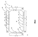
- FIG. 5 is a further planar top view illustrating the minimally-invasive portal system of FIG. 1 , specifically a multi-level configuration of the minimally-invasive portal system;
- FIG. 6 is a still further planar top view illustrating the minimally-invasive portal system of FIGS. 1 , 3 , and 4 , the minimally-invasive portal system incorporating an optional handle attachment;
- FIG. 7 is a still further planar top view illustrating the minimally-invasive portal system of FIGS. 1 , 3 , and 4 , the minimally-invasive portal system incorporating an optional adjustable table attachment;
- FIG. 8 is a perspective view illustrating one exemplary embodiment of the one or more retaining clips of FIG. 1 ;
- FIG. 9 is a cross-sectional side view illustrating one exemplary embodiment of the plurality of adjustment mechanisms of FIGS. 1 and 3 - 7 ;
- FIG. 10 is another cross-sectional side view illustrating another exemplary embodiment of the plurality of adjustment mechanisms of FIGS. 1 and 3 - 7 .
- the present invention provides a minimally-invasive portal system that provides enhanced access to and visualization of an area of interest within the body of a human patient, a veterinary patient, or the like, such that a surgical procedure may be performed, especially a surgical procedure involving the lumbar or cervical spine of the patient.
- the minimally-invasive portal system of the present invention is relatively simple to insert, adjust, and remove, and provides an adequate field of view.
- the minimally-invasive portal system 10 includes an access tube 12 that is selectively positioned through the skin 14 of a patient adjacent to an area of interest (i.e. an area to be operated on or otherwise visualized).
- the access tube 12 may be positioned using one or more conventional dilation tubes, well known to those of ordinary skill in the art, for successively dilating the skin 14 and musculature of the patient to greater diameters or dimensions.
- the access tube 12 has a substantially circular, oval-shaped, square-shaped, or rectangular cross-sectional shape, although other suitable cross-sectional shapes may be utilized.
- the access tube 12 may have any suitable diameter, dimension, and/or depth suitable for the procedure to be performed.
- One or more retractor devices 16 are selectively disposed concentrically within/through the access tube 12 .
- Each of the one or more retractor devices 16 includes a top portion 18 which remains external to the body of the patient, a central portion 20 which is disposed concentrically within the access tube 12 , and a bottom portion 22 which is disposed through and protrudes beneath the access tube 12 into the body of the patient.
- the bottom portion 22 of each of the one or more retractor devices 16 is disposed at a predetermined angle ( ⁇ ) 24 relative to the central portion 20 of each of the one or more retractor devices 16 , the predetermined angle ( ⁇ ) 24 varying from about 0 degrees to about 45 degrees, in an exemplary embodiment of the present invention.
- the predetermined angle ( ⁇ ) 24 is adjustable during the procedure to be performed.
- the central portion 20 and the bottom portion 22 of each of the one or more retractor devices 16 may be sized and/or shaped such that they fit comfortably within/through the access tube 12 and provide visualization of/access to an exposed area 26 via a portal 28 .
- the top portion 18 of each of the one or more retractor devices 16 includes a post 30 and handle 32 , which may be selectively removable.
- one or more retaining clips 34 may be used to selectively couple the one or more retractor devices 16 to the access tube 12 .
- the access tube 12 incorporates one or more adjustment mechanisms 36 (also described in greater detail herein below).
- the one or more adjustment mechanisms 36 are each operable for selectively adjusting the diameter or dimensions of the access tube 12 , and, correspondingly, the separation of the one or more retractor devices 16 , the diameter or dimensions of the portal 28 , and the diameter or dimensions of the exposed area 26 , providing visualization and/or access flexibility.
- the access tube 12 may be positioned using one or more conventional dilation tubes 40 , well known to those of ordinary skill in the art, for successively dilating the skin 14 and musculature of the patient to greater diameters or dimensions.
- the dilation tube(s) 40 is/are first inserted through the skin 14 and musculature of the patient, either singly or successively.
- the access tube 12 is then disposed concentrically about the dilation tube(s) 40 .
- the dilation tube(s) 40 is/are removed, leaving the access tube 12 in place.
- the one or more retractor devices 16 FIG. 1
- the appropriate adjustments are made using the one or more adjustment mechanisms 36 ( FIG. 1 ).
- the access tube 12 consists of a plurality of segments 50 which are selectively adjustable relative to one another via a plurality of adjustment areas 52 .
- the plurality of segments 50 of the access tube 12 may separate from one another (as shown in FIG. 3 ), or they may overlap in the plurality of adjustment areas 52 (not shown in FIG. 3 ).
- a portion of one of the plurality of segments 50 may be substantially disposed within and move relative to another one of the plurality of segments 50 .
- the plurality of segments 50 of the access tube 12 are selectively adjustable relative to one another using the one or more adjustment mechanisms 36 (described in greater detail herein below).
- the one or more adjustment mechanisms 36 are each operable for selectively adjusting the diameter or dimensions of the access tube 12 , and, correspondingly, the separation of the one or more retractor devices 16 ( FIG. 1 ), the diameter or dimensions of the portal 28 , and the diameter or dimensions of the exposed area 26 ( FIG. 1 ), providing visualization and/or access flexibility. It should be noted that a single-level configuration of the minimally-invasive portal system 10 of the present invention is shown in FIG. 3 , meaning that there is one adjustment area 52 for any given portion or “side” of the access tube 12 .
- each of the one or more retractor devices 16 includes a top portion 18 which remains external to the body of the patient and a central portion 20 which is disposed concentrically within the access tube 12 .
- the top portion 18 of each of the one or more retractor devices 16 includes a handle 32 , which may be selectively removable. The handle 32 allows a user to effectively grasp and manipulate the retractor device 16 .
- the one or more retaining clips 34 FIG. 1 (described in greater detail herein below) that are used to selectively couple the one or more retractor devices 16 to the access tube 12 are not shown in FIG. 4 .
- a multi-level configuration of the minimally-invasive portal system 10 includes a plurality of adjustment areas 52 for one or more portions or “sides” of the access tube 12 , providing enhanced adjustment flexibility.
- the minimally-invasive portal system 10 includes either a handle attachment 60 ( FIG. 6 ) or a table attachment 70 ( FIG. 7 ) attached to the one or more adjustment mechanisms 36 and/or the access tube 12 .
- Both the handle attachment 60 and the table attachment 70 protrude substantially upwardly and outwardly from the one or more attachment mechanisms 36 and/or the access tube 12 .
- the handle attachment 60 allows a user to effectively grasp and manipulate the one or more attachment mechanisms 36 and/or the access tube 12 .
- the table attachment 70 allows the one or more attachment mechanisms 36 and/or the access tube 12 to be securely fastened to an operating table or the like, thereby effectively stabilizing the minimally-invasive portal system 10 of the present invention.
- each of the one or more retaining clips 34 includes a body portion 80 and a tongue portion 82 .
- the body portion 80 of each of the one or more retaining clips 34 is substantially U-shaped, or has another suitable shape for selectively coupling the one or more retractor devices 16 ( FIGS. 1 and 4 ) to the access tube 12 ( FIGS. 1-7 ).
- the tongue portion 82 of each of the one or more retaining clips 34 defines an opening 84 through which the post 30 ( FIGS. 1 and 4 ) and handle 32 ( FIGS. 1 and 4 ) of each of the one or more retractor devices 16 may pass.
- the tongue portion 82 of the retaining clip 34 is grasped with the thumb and index finger of the user, advanced downward over the post 30 and handle 32 of the retractor device 16 , and engages/retains the retractor device 16 .
- FIGS. 9 and 10 show two exemplary embodiments of the adjustment mechanism 36 of the present invention.
- the adjustment mechanism 36 may consist of an extendable/retractable device that is suitable for selectively adjusting the diameter/dimensions of the access tube 12 ( FIGS. 1-8 ).
- FIG. 9 shows an adjustment mechanism 36 that incorporates a screw 90 and a retaining band 92 .
- FIG. 10 shows an adjustment mechanism 36 that incorporates a screw 90 , a retaining band 92 , and one or more stabilizing bands 94 .
- any medically/surgically suitable materials may be used to manufacture the components of the minimally-invasive portal system of the present invention.
- Such materials are well known to those of ordinary skill in the art and may include, but are not limited to, suitable metals, plastics, and composite materials.
Abstract
Description
Claims (9)
Priority Applications (2)
| Application Number | Priority Date | Filing Date | Title |
|---|---|---|---|
| US11/323,002 US8568305B2 (en) | 2004-12-29 | 2005-12-29 | Minimally-invasive portal system for performing lumbar decompression, instrumented fusion/stabilization, and the like |
| US14/064,942 US9265491B2 (en) | 2004-12-29 | 2013-10-28 | Minimally-invasive portal methods for performing lumbar decompression, instrumented fusion/stabilization, and the like |
Applications Claiming Priority (2)
| Application Number | Priority Date | Filing Date | Title |
|---|---|---|---|
| US63993604P | 2004-12-29 | 2004-12-29 | |
| US11/323,002 US8568305B2 (en) | 2004-12-29 | 2005-12-29 | Minimally-invasive portal system for performing lumbar decompression, instrumented fusion/stabilization, and the like |
Related Child Applications (1)
| Application Number | Title | Priority Date | Filing Date |
|---|---|---|---|
| US14/064,942 Continuation US9265491B2 (en) | 2004-12-29 | 2013-10-28 | Minimally-invasive portal methods for performing lumbar decompression, instrumented fusion/stabilization, and the like |
Publications (2)
| Publication Number | Publication Date |
|---|---|
| US20060142642A1 US20060142642A1 (en) | 2006-06-29 |
| US8568305B2 true US8568305B2 (en) | 2013-10-29 |
Family
ID=36612716
Family Applications (2)
| Application Number | Title | Priority Date | Filing Date |
|---|---|---|---|
| US11/323,002 Expired - Fee Related US8568305B2 (en) | 2004-12-29 | 2005-12-29 | Minimally-invasive portal system for performing lumbar decompression, instrumented fusion/stabilization, and the like |
| US14/064,942 Expired - Fee Related US9265491B2 (en) | 2004-12-29 | 2013-10-28 | Minimally-invasive portal methods for performing lumbar decompression, instrumented fusion/stabilization, and the like |
Family Applications After (1)
| Application Number | Title | Priority Date | Filing Date |
|---|---|---|---|
| US14/064,942 Expired - Fee Related US9265491B2 (en) | 2004-12-29 | 2013-10-28 | Minimally-invasive portal methods for performing lumbar decompression, instrumented fusion/stabilization, and the like |
Country Status (1)
| Country | Link |
|---|---|
| US (2) | US8568305B2 (en) |
Cited By (1)
| Publication number | Priority date | Publication date | Assignee | Title |
|---|---|---|---|---|
| US9265491B2 (en) | 2004-12-29 | 2016-02-23 | U.S. Spine, Inc. | Minimally-invasive portal methods for performing lumbar decompression, instrumented fusion/stabilization, and the like |
Families Citing this family (31)
| Publication number | Priority date | Publication date | Assignee | Title |
|---|---|---|---|---|
| DE10154163A1 (en) | 2001-11-03 | 2003-05-22 | Advanced Med Tech | Device for straightening and stabilizing the spine |
| US8979931B2 (en) | 2006-12-08 | 2015-03-17 | DePuy Synthes Products, LLC | Nucleus replacement device and method |
| US8062217B2 (en) | 2007-01-26 | 2011-11-22 | Theken Spine, Llc | Surgical retractor with removable blades and method of use |
| CA2701504A1 (en) | 2007-10-05 | 2009-04-09 | Synthes Usa, Llc | Dilation system and method of using the same |
| JP5627667B2 (en) | 2009-04-03 | 2014-11-19 | ハーデンブルック、ミッチェル エイ.HARDENBROOK,Mitchell A. | Surgical retractor assembly |
| JP6396657B2 (en) | 2010-10-01 | 2018-09-26 | アプライド メディカル リソーシーズ コーポレイション | Natural orifice surgery system |
| US9622779B2 (en) | 2011-10-27 | 2017-04-18 | DePuy Synthes Products, Inc. | Method and devices for a sub-splenius / supra-levator scapulae surgical access technique |
| WO2013067179A2 (en) | 2011-11-01 | 2013-05-10 | Synthes Usa, Llc | Dilation system |
| US8795167B2 (en) | 2011-11-15 | 2014-08-05 | Baxano Surgical, Inc. | Spinal therapy lateral approach access instruments |
| US9265490B2 (en) | 2012-04-16 | 2016-02-23 | DePuy Synthes Products, Inc. | Detachable dilator blade |
| US9480855B2 (en) | 2012-09-26 | 2016-11-01 | DePuy Synthes Products, Inc. | NIR/red light for lateral neuroprotection |
| KR102196662B1 (en) | 2013-03-15 | 2020-12-30 | 어플라이드 메디컬 리소시스 코포레이션 | Trocar surgical seal |
| US9980737B2 (en) | 2014-08-04 | 2018-05-29 | Medos International Sarl | Flexible transport auger |
| US10264959B2 (en) | 2014-09-09 | 2019-04-23 | Medos International Sarl | Proximal-end securement of a minimally invasive working channel |
| US9924979B2 (en) | 2014-09-09 | 2018-03-27 | Medos International Sarl | Proximal-end securement of a minimally invasive working channel |
| US10111712B2 (en) | 2014-09-09 | 2018-10-30 | Medos International Sarl | Proximal-end securement of a minimally invasive working channel |
| US10786264B2 (en) | 2015-03-31 | 2020-09-29 | Medos International Sarl | Percutaneous disc clearing device |
| US11439380B2 (en) | 2015-09-04 | 2022-09-13 | Medos International Sarl | Surgical instrument connectors and related methods |
| US11672562B2 (en) | 2015-09-04 | 2023-06-13 | Medos International Sarl | Multi-shield spinal access system |
| US11744447B2 (en) | 2015-09-04 | 2023-09-05 | Medos International | Surgical visualization systems and related methods |
| CN113143355A (en) | 2015-09-04 | 2021-07-23 | 美多斯国际有限公司 | Multi-shield spinal access system |
| US10987129B2 (en) | 2015-09-04 | 2021-04-27 | Medos International Sarl | Multi-shield spinal access system |
| DE102015012964B4 (en) * | 2015-10-08 | 2018-12-27 | Karl Storz Se & Co. Kg | Access system for endoscopic operations |
| US10299838B2 (en) | 2016-02-05 | 2019-05-28 | Medos International Sarl | Method and instruments for interbody fusion and posterior fixation through a single incision |
| EP3457950B8 (en) * | 2016-05-20 | 2023-07-26 | Choice Spine, LLC | Access instruments to extend a surgical working channel |
| US11013530B2 (en) | 2019-03-08 | 2021-05-25 | Medos International Sarl | Surface features for device retention |
| US11241252B2 (en) | 2019-03-22 | 2022-02-08 | Medos International Sarl | Skin foundation access portal |
| US11129727B2 (en) | 2019-03-29 | 2021-09-28 | Medos International Sari | Inflatable non-distracting intervertebral implants and related methods |
| US11813026B2 (en) | 2019-04-05 | 2023-11-14 | Medos International Sarl | Systems, devices, and methods for providing surgical trajectory guidance |
| US11944356B2 (en) | 2019-11-22 | 2024-04-02 | Medos International Sarl | Control member for adjusting access tube position, and related systems and methods |
| US11771517B2 (en) | 2021-03-12 | 2023-10-03 | Medos International Sarl | Camera position indication systems and methods |
Citations (20)
| Publication number | Priority date | Publication date | Assignee | Title |
|---|---|---|---|---|
| US497064A (en) * | 1893-05-09 | Speculum | ||
| US1796072A (en) * | 1928-10-25 | 1931-03-10 | Walter K Baer | Speculum |
| US2300040A (en) * | 1940-05-31 | 1942-10-27 | Frank A Betts | Surgical speculum |
| US2623517A (en) * | 1950-06-29 | 1952-12-30 | Barlow Israel Owen | Surgical abdominal retractor |
| US3070088A (en) * | 1961-02-02 | 1962-12-25 | Brahos Nicholas George | Surgical retractor device |
| US3463144A (en) * | 1966-06-13 | 1969-08-26 | Daniel O Hammond | Surgical retractor |
| US3965890A (en) * | 1974-10-18 | 1976-06-29 | William Kohlmann Gauthier | Surgical retractor |
| US5231974A (en) * | 1991-05-31 | 1993-08-03 | Giglio Steven R | Self retaining retractor |
| US5520610A (en) * | 1991-05-31 | 1996-05-28 | Giglio; Steven R. | Self retaining retractor |
| US5688223A (en) * | 1995-11-08 | 1997-11-18 | Minnesota Scientific, Inc. | Retractor support with adjustable retractor blades |
| US5980569A (en) * | 1997-09-19 | 1999-11-09 | United States Surgical Corp. | Prosthetic valve holder and method of use |
| US6102853A (en) * | 1998-01-23 | 2000-08-15 | United States Surgical Corporation | Surgical instrument |
| US6113535A (en) * | 1998-01-23 | 2000-09-05 | Ethicon Endo-Surgery, Inc. | Surgical retraction apparatus |
| US6206826B1 (en) * | 1997-12-18 | 2001-03-27 | Sdgi Holdings, Inc. | Devices and methods for percutaneous surgery |
| US6254533B1 (en) * | 2000-07-07 | 2001-07-03 | Dexterity Surgical, Inc. | Retractor assembly and method for surgical procedures |
| US20040176665A1 (en) * | 2002-06-26 | 2004-09-09 | Branch Charles L. | Instruments and methods for minimally invasive tissue retraction and surgery |
| US20040230100A1 (en) * | 2003-05-16 | 2004-11-18 | Shluzas Alan E. | Access device for minimally invasive surgery |
| US20050159651A1 (en) * | 2003-12-18 | 2005-07-21 | Depuy Spine, Inc. | Surgical retractor systems and illuminated cannulae |
| US20060135852A1 (en) * | 2004-12-20 | 2006-06-22 | Tibor Koros | Rotatable holder assembly for a surgical retractor blade |
| US20060142642A1 (en) * | 2004-12-29 | 2006-06-29 | Lins Robert E | Minimally-invasive portal system for performing lumbar decompression, instrumented fusion/stabilization, and the like |
Family Cites Families (3)
| Publication number | Priority date | Publication date | Assignee | Title |
|---|---|---|---|---|
| US196600A (en) * | 1877-10-30 | Improvement in speculums | ||
| US3788318A (en) * | 1972-06-12 | 1974-01-29 | S Kim | Expandable cannular, especially for medical purposes |
| US6849064B2 (en) * | 2002-10-25 | 2005-02-01 | James S. Hamada | Minimal access lumbar diskectomy instrumentation and method |
-
2005
- 2005-12-29 US US11/323,002 patent/US8568305B2/en not_active Expired - Fee Related
-
2013
- 2013-10-28 US US14/064,942 patent/US9265491B2/en not_active Expired - Fee Related
Patent Citations (20)
| Publication number | Priority date | Publication date | Assignee | Title |
|---|---|---|---|---|
| US497064A (en) * | 1893-05-09 | Speculum | ||
| US1796072A (en) * | 1928-10-25 | 1931-03-10 | Walter K Baer | Speculum |
| US2300040A (en) * | 1940-05-31 | 1942-10-27 | Frank A Betts | Surgical speculum |
| US2623517A (en) * | 1950-06-29 | 1952-12-30 | Barlow Israel Owen | Surgical abdominal retractor |
| US3070088A (en) * | 1961-02-02 | 1962-12-25 | Brahos Nicholas George | Surgical retractor device |
| US3463144A (en) * | 1966-06-13 | 1969-08-26 | Daniel O Hammond | Surgical retractor |
| US3965890A (en) * | 1974-10-18 | 1976-06-29 | William Kohlmann Gauthier | Surgical retractor |
| US5231974A (en) * | 1991-05-31 | 1993-08-03 | Giglio Steven R | Self retaining retractor |
| US5520610A (en) * | 1991-05-31 | 1996-05-28 | Giglio; Steven R. | Self retaining retractor |
| US5688223A (en) * | 1995-11-08 | 1997-11-18 | Minnesota Scientific, Inc. | Retractor support with adjustable retractor blades |
| US5980569A (en) * | 1997-09-19 | 1999-11-09 | United States Surgical Corp. | Prosthetic valve holder and method of use |
| US6206826B1 (en) * | 1997-12-18 | 2001-03-27 | Sdgi Holdings, Inc. | Devices and methods for percutaneous surgery |
| US6102853A (en) * | 1998-01-23 | 2000-08-15 | United States Surgical Corporation | Surgical instrument |
| US6113535A (en) * | 1998-01-23 | 2000-09-05 | Ethicon Endo-Surgery, Inc. | Surgical retraction apparatus |
| US6254533B1 (en) * | 2000-07-07 | 2001-07-03 | Dexterity Surgical, Inc. | Retractor assembly and method for surgical procedures |
| US20040176665A1 (en) * | 2002-06-26 | 2004-09-09 | Branch Charles L. | Instruments and methods for minimally invasive tissue retraction and surgery |
| US20040230100A1 (en) * | 2003-05-16 | 2004-11-18 | Shluzas Alan E. | Access device for minimally invasive surgery |
| US20050159651A1 (en) * | 2003-12-18 | 2005-07-21 | Depuy Spine, Inc. | Surgical retractor systems and illuminated cannulae |
| US20060135852A1 (en) * | 2004-12-20 | 2006-06-22 | Tibor Koros | Rotatable holder assembly for a surgical retractor blade |
| US20060142642A1 (en) * | 2004-12-29 | 2006-06-29 | Lins Robert E | Minimally-invasive portal system for performing lumbar decompression, instrumented fusion/stabilization, and the like |
Cited By (1)
| Publication number | Priority date | Publication date | Assignee | Title |
|---|---|---|---|---|
| US9265491B2 (en) | 2004-12-29 | 2016-02-23 | U.S. Spine, Inc. | Minimally-invasive portal methods for performing lumbar decompression, instrumented fusion/stabilization, and the like |
Also Published As
| Publication number | Publication date |
|---|---|
| US20060142642A1 (en) | 2006-06-29 |
| US20140051932A1 (en) | 2014-02-20 |
| US9265491B2 (en) | 2016-02-23 |
Similar Documents
| Publication | Publication Date | Title |
|---|---|---|
| US8568305B2 (en) | Minimally-invasive portal system for performing lumbar decompression, instrumented fusion/stabilization, and the like | |
| US20210169461A1 (en) | Dilation system and method of using the same | |
| US7189234B2 (en) | Interspinous process implant sizer and distractor with a split head and size indicator and method | |
| US9179926B2 (en) | Minimally invasive spinal fixation guide systems and methods | |
| US8114085B2 (en) | Percutaneous registration-and-access tool for minimally invasive spinal surgery | |
| US8007517B2 (en) | Interspinous distraction devices and associated methods of insertion | |
| US8147525B2 (en) | Bone anchor assembly and methods of use | |
| US20060030858A1 (en) | Methods and devices for retracting tissue in minimally invasive surgery | |
| US8808172B2 (en) | Method and apparatus for laterally accessing an intervertebral disc space | |
| US7918875B2 (en) | Interspinous distraction devices and associated methods of insertion | |
| US20070016223A1 (en) | Apparatus and methods for shielding body structures during surgery | |
| US9924933B2 (en) | System and methods for performing spinal fusion surgery | |
| US20080234550A1 (en) | Minimally Traumatic Portal | |
| US10660631B1 (en) | Pedicle screw mounted retractor system | |
| US9439641B2 (en) | Exposure apparatus for posterior spinal minimally invasive screw placement surgery | |
| US5881730A (en) | Surgical hand support apparatus | |
| WO2005060534A3 (en) | Methods and devices for minimally invasive spinal fixation element placement | |
| US20120323280A1 (en) | Methods, tools and devices for spinal fixation | |
| US20210346038A1 (en) | Patient-specific navigation guide | |
| US11712271B2 (en) | Device and method to establish stabilization of the cervical spine without implantation of hardware or violation of the cortical bone | |
| CN102397087B (en) | Thoracic access port | |
| CN114983502A (en) | Bone implant with tethered bands | |
| US8690878B2 (en) | Flexible anchor extenders | |
| CN106999216B (en) | Lateral mass fixation system | |
| Garg et al. | Minimally Invasive Correction for Adolescent Idiopathic Scoliosis |
Legal Events
| Date | Code | Title | Description |
|---|---|---|---|
| AS | Assignment |
Owner name: SUMNER TECHNOLOGIES, LLC, FLORIDA Free format text: ASSIGNMENT OF ASSIGNORS INTEREST;ASSIGNORS:LINS, ROBERT E.;LINS, LOREN E.;SIMOVITCH, HARVEY;REEL/FRAME:024988/0103 Effective date: 20050916 Owner name: U.S. SPINAL TECHNOLOGIES, LLC, FLORIDA Free format text: ASSIGNMENT OF ASSIGNORS INTEREST;ASSIGNOR:SUMNER TECHNOLOGIES, LLC;REEL/FRAME:024988/0284 Effective date: 20051226 |
|
| AS | Assignment |
Owner name: KARL KIPKE, AS COLLATERAL AGENT, TEXAS Free format text: SECURITY AGREEMENT;ASSIGNOR:AMEDICA CORPORATION;REEL/FRAME:025900/0168 Effective date: 20110303 |
|
| AS | Assignment |
Owner name: U.S. SPINE, INC., UTAH Free format text: CHANGE OF NAME;ASSIGNOR:U.S. SPINAL TECHNOLOGIES, LLC;REEL/FRAME:026139/0963 Effective date: 20080701 |
|
| AS | Assignment |
Owner name: GE CAPITAL EQUITY INVESTMENTS, INC. C/O GE HEALTHC Free format text: SECURITY AGREEMENT;ASSIGNORS:AMEDICA CORPORATION;US SPINE, INC.;REEL/FRAME:029495/0211 Effective date: 20121214 Owner name: AMEDICA CORPORATION, UTAH Free format text: RELEASE BY SECURED PARTY;ASSIGNOR:AS COLLATERAL AGENT, KARL KIPKE;REEL/FRAME:029492/0321 Effective date: 20121214 |
|
| STCF | Information on status: patent grant |
Free format text: PATENTED CASE |
|
| AS | Assignment |
Owner name: GENERAL ELECTRIC CAPITAL CORPORATION, MARYLAND Free format text: CORRECTIVE ASSIGNMENT TO CORRECT THE NAME OF THE ASSIGNEE PREVIOUSLY RECORDED ON REEL 029495 FRAME 0211. ASSIGNOR(S) HEREBY CONFIRMS THE ASSIGNOR: AMEDICA CORPORATION ASSIGNOR: US SPINE, INC. ASSIGNEE: GENERAL ELECTRIC CAPITAL CORPORATION;ASSIGNORS:AMEDICA CORPORATION;US SPINE, INC.;REEL/FRAME:031581/0831 Effective date: 20121214 |
|
| FPAY | Fee payment |
Year of fee payment: 4 |
|
| AS | Assignment |
Owner name: AMEDICA CORPORATION, UTAH Free format text: ASSIGNMENT OF ASSIGNORS INTEREST;ASSIGNOR:U.S. SPINE, INC.;REEL/FRAME:044795/0780 Effective date: 20180127 |
|
| AS | Assignment |
Owner name: US SPINE, INC., UTAH Free format text: RELEASE BY SECURED PARTY;ASSIGNOR:GENERAL ELECTRIC CAPITAL CORPORATION;REEL/FRAME:047199/0313 Effective date: 20140630 Owner name: AMEDICA CORPORATION, UTAH Free format text: RELEASE BY SECURED PARTY;ASSIGNOR:GENERAL ELECTRIC CAPITAL CORPORATION;REEL/FRAME:047199/0313 Effective date: 20140630 |
|
| AS | Assignment |
Owner name: AMEDICA CORPORATION, UTAH Free format text: CORRECTIVE ASSIGNMENT TO CORRECT THE PATENT NUMBER PREVIOUSLY RECORDED AT REEL: 047199 FRAME: 0313. ASSIGNOR(S) HEREBY CONFIRMS THE RELEASE OF SECURITY INTEREST;ASSIGNOR:GENERAL ELECTRIC CAPITAL CORPORATION;REEL/FRAME:047403/0953 Effective date: 20140630 Owner name: US SPINE, INC., UTAH Free format text: CORRECTIVE ASSIGNMENT TO CORRECT THE PATENT NUMBER PREVIOUSLY RECORDED AT REEL: 047199 FRAME: 0313. ASSIGNOR(S) HEREBY CONFIRMS THE RELEASE OF SECURITY INTEREST;ASSIGNOR:GENERAL ELECTRIC CAPITAL CORPORATION;REEL/FRAME:047403/0953 Effective date: 20140630 |
|
| AS | Assignment |
Owner name: CTL MEDICAL CORPORATION, TEXAS Free format text: ASSIGNMENT OF ASSIGNORS INTEREST;ASSIGNORS:AMEDICA CORPORATION;U.S. SPINE, INC.;REEL/FRAME:051368/0261 Effective date: 20181001 |
|
| AS | Assignment |
Owner name: SOURCE CAPITAL CREDIT OPPORTUNITIES FUND III, LP, GEORGIA Free format text: SECURITY INTEREST;ASSIGNOR:CTL MEDICAL CORPORATION;REEL/FRAME:056417/0606 Effective date: 20210513 |
|
| AS | Assignment |
Owner name: STERLING NATIONAL BANK, NEW YORK Free format text: SECURITY AGREEMENT;ASSIGNOR:CTL MEDICAL CORPORATION;REEL/FRAME:056595/0562 Effective date: 20210513 |
|
| FEPP | Fee payment procedure |
Free format text: MAINTENANCE FEE REMINDER MAILED (ORIGINAL EVENT CODE: REM.); ENTITY STATUS OF PATENT OWNER: SMALL ENTITY |
|
| LAPS | Lapse for failure to pay maintenance fees |
Free format text: PATENT EXPIRED FOR FAILURE TO PAY MAINTENANCE FEES (ORIGINAL EVENT CODE: EXP.); ENTITY STATUS OF PATENT OWNER: SMALL ENTITY |
|
| STCH | Information on status: patent discontinuation |
Free format text: PATENT EXPIRED DUE TO NONPAYMENT OF MAINTENANCE FEES UNDER 37 CFR 1.362 |
|
| FP | Lapsed due to failure to pay maintenance fee |
Effective date: 20211029 |