US8535357B2 - Continuous phase compositions for ACL repair - Google Patents
Continuous phase compositions for ACL repair Download PDFInfo
- Publication number
- US8535357B2 US8535357B2 US11/702,448 US70244807A US8535357B2 US 8535357 B2 US8535357 B2 US 8535357B2 US 70244807 A US70244807 A US 70244807A US 8535357 B2 US8535357 B2 US 8535357B2
- Authority
- US
- United States
- Prior art keywords
- implant
- polymer
- screw
- pores
- composite
- Prior art date
- Legal status (The legal status is an assumption and is not a legal conclusion. Google has not performed a legal analysis and makes no representation as to the accuracy of the status listed.)
- Active, expires
Links
Images


Classifications
-
- A—HUMAN NECESSITIES
- A61—MEDICAL OR VETERINARY SCIENCE; HYGIENE
- A61F—FILTERS IMPLANTABLE INTO BLOOD VESSELS; PROSTHESES; DEVICES PROVIDING PATENCY TO, OR PREVENTING COLLAPSING OF, TUBULAR STRUCTURES OF THE BODY, e.g. STENTS; ORTHOPAEDIC, NURSING OR CONTRACEPTIVE DEVICES; FOMENTATION; TREATMENT OR PROTECTION OF EYES OR EARS; BANDAGES, DRESSINGS OR ABSORBENT PADS; FIRST-AID KITS
- A61F2/00—Filters implantable into blood vessels; Prostheses, i.e. artificial substitutes or replacements for parts of the body; Appliances for connecting them with the body; Devices providing patency to, or preventing collapsing of, tubular structures of the body, e.g. stents
- A61F2/02—Prostheses implantable into the body
- A61F2/08—Muscles; Tendons; Ligaments
- A61F2/0811—Fixation devices for tendons or ligaments
-
- A—HUMAN NECESSITIES
- A61—MEDICAL OR VETERINARY SCIENCE; HYGIENE
- A61B—DIAGNOSIS; SURGERY; IDENTIFICATION
- A61B17/00—Surgical instruments, devices or methods, e.g. tourniquets
- A61B17/56—Surgical instruments or methods for treatment of bones or joints; Devices specially adapted therefor
- A61B17/58—Surgical instruments or methods for treatment of bones or joints; Devices specially adapted therefor for osteosynthesis, e.g. bone plates, screws, setting implements or the like
- A61B17/68—Internal fixation devices, including fasteners and spinal fixators, even if a part thereof projects from the skin
- A61B17/84—Fasteners therefor or fasteners being internal fixation devices
- A61B17/86—Pins or screws or threaded wires; nuts therefor
- A61B17/866—Material or manufacture
-
- A—HUMAN NECESSITIES
- A61—MEDICAL OR VETERINARY SCIENCE; HYGIENE
- A61B—DIAGNOSIS; SURGERY; IDENTIFICATION
- A61B17/00—Surgical instruments, devices or methods, e.g. tourniquets
- A61B17/56—Surgical instruments or methods for treatment of bones or joints; Devices specially adapted therefor
- A61B17/58—Surgical instruments or methods for treatment of bones or joints; Devices specially adapted therefor for osteosynthesis, e.g. bone plates, screws, setting implements or the like
- A61B17/68—Internal fixation devices, including fasteners and spinal fixators, even if a part thereof projects from the skin
- A61B17/84—Fasteners therefor or fasteners being internal fixation devices
- A61B17/86—Pins or screws or threaded wires; nuts therefor
- A61B17/864—Pins or screws or threaded wires; nuts therefor hollow, e.g. with socket or cannulated
-
- A—HUMAN NECESSITIES
- A61—MEDICAL OR VETERINARY SCIENCE; HYGIENE
- A61B—DIAGNOSIS; SURGERY; IDENTIFICATION
- A61B17/00—Surgical instruments, devices or methods, e.g. tourniquets
- A61B2017/00004—(bio)absorbable, (bio)resorbable, resorptive
-
- A—HUMAN NECESSITIES
- A61—MEDICAL OR VETERINARY SCIENCE; HYGIENE
- A61F—FILTERS IMPLANTABLE INTO BLOOD VESSELS; PROSTHESES; DEVICES PROVIDING PATENCY TO, OR PREVENTING COLLAPSING OF, TUBULAR STRUCTURES OF THE BODY, e.g. STENTS; ORTHOPAEDIC, NURSING OR CONTRACEPTIVE DEVICES; FOMENTATION; TREATMENT OR PROTECTION OF EYES OR EARS; BANDAGES, DRESSINGS OR ABSORBENT PADS; FIRST-AID KITS
- A61F2/00—Filters implantable into blood vessels; Prostheses, i.e. artificial substitutes or replacements for parts of the body; Appliances for connecting them with the body; Devices providing patency to, or preventing collapsing of, tubular structures of the body, e.g. stents
- A61F2/02—Prostheses implantable into the body
- A61F2/08—Muscles; Tendons; Ligaments
- A61F2/0811—Fixation devices for tendons or ligaments
- A61F2002/0847—Mode of fixation of anchor to tendon or ligament
- A61F2002/0858—Fixation of tendon or ligament between anchor and bone, e.g. interference screws, wedges
-
- A—HUMAN NECESSITIES
- A61—MEDICAL OR VETERINARY SCIENCE; HYGIENE
- A61F—FILTERS IMPLANTABLE INTO BLOOD VESSELS; PROSTHESES; DEVICES PROVIDING PATENCY TO, OR PREVENTING COLLAPSING OF, TUBULAR STRUCTURES OF THE BODY, e.g. STENTS; ORTHOPAEDIC, NURSING OR CONTRACEPTIVE DEVICES; FOMENTATION; TREATMENT OR PROTECTION OF EYES OR EARS; BANDAGES, DRESSINGS OR ABSORBENT PADS; FIRST-AID KITS
- A61F2/00—Filters implantable into blood vessels; Prostheses, i.e. artificial substitutes or replacements for parts of the body; Appliances for connecting them with the body; Devices providing patency to, or preventing collapsing of, tubular structures of the body, e.g. stents
- A61F2/02—Prostheses implantable into the body
- A61F2/08—Muscles; Tendons; Ligaments
- A61F2/0811—Fixation devices for tendons or ligaments
- A61F2002/0876—Position of anchor in respect to the bone
- A61F2002/0882—Anchor in or on top of a bone tunnel, i.e. a hole running through the entire bone
-
- A—HUMAN NECESSITIES
- A61—MEDICAL OR VETERINARY SCIENCE; HYGIENE
- A61F—FILTERS IMPLANTABLE INTO BLOOD VESSELS; PROSTHESES; DEVICES PROVIDING PATENCY TO, OR PREVENTING COLLAPSING OF, TUBULAR STRUCTURES OF THE BODY, e.g. STENTS; ORTHOPAEDIC, NURSING OR CONTRACEPTIVE DEVICES; FOMENTATION; TREATMENT OR PROTECTION OF EYES OR EARS; BANDAGES, DRESSINGS OR ABSORBENT PADS; FIRST-AID KITS
- A61F2250/00—Special features of prostheses classified in groups A61F2/00 - A61F2/26 or A61F2/82 or A61F9/00 or A61F11/00 or subgroups thereof
- A61F2250/0014—Special features of prostheses classified in groups A61F2/00 - A61F2/26 or A61F2/82 or A61F9/00 or A61F11/00 or subgroups thereof having different values of a given property or geometrical feature, e.g. mechanical property or material property, at different locations within the same prosthesis
- A61F2250/003—Special features of prostheses classified in groups A61F2/00 - A61F2/26 or A61F2/82 or A61F9/00 or A61F11/00 or subgroups thereof having different values of a given property or geometrical feature, e.g. mechanical property or material property, at different locations within the same prosthesis differing in adsorbability or resorbability, i.e. in adsorption or resorption time
Definitions
- the human musculoskeletal system is composed of a variety of tissues including bone, ligaments, cartilage, muscle, and tendons. Tissue damage or deformity stemming from trauma, pathological degeneration, or congenital conditions often necessitates surgical intervention to restore function. During these procedures, surgeons can use orthopedic implants to restore function to the site and facilitate the natural healing process.
- ACL anterior cruciate ligaments
- PCL posterior cruciate ligaments
- the ACL and PCL procedures may be performed arthroscopically and, generally, involve preparing a bone tunnel through the tibia and adjacent femur, placing a ligament graft extending between the two bone tunnels, and securing each end of the graft within its respective tunnel.
- Various methods of graft attachment are known, including the use of interference screws to secure the graft against the wall of the graft tunnel.
- a metal interference screw may be used to wedge a graft bone block to the wall of the graft tunnel. If a bioabsorbable interference screw is used, the graft may be wedged directly against the bone by the interference screw, without a bone block.
- Interference screws are generally composed of non-resorbable metals, ceramics, polymers, and composites. Interference screws for anchoring ligaments to bone are typically fabricated from medically approved metallic materials that are not naturally absorbed by the body. A disadvantage of such interference screws is that once healing is complete, an additional surgical procedure may be required to remove the interference screw from the patient.
- Metallic interference screws may include a threaded shank joined to an enlarged head having a transverse slot or hexagonal socket formed therein to engage a similarly configured, single blade or hexagonal rotatable driver for turning the interference screw into the bone. The enlarged heads on such interference screws can protrude from the graft tunnel and can cause chronic irritation and inflammation of surrounding body tissue.
- Permanent metallic interference screws in movable joints can, in certain instances, cause abrading of ligaments during normal motion of the joint. Interference screws occasionally back out after insertion, protruding into surrounding tissue and causing discomfort. Furthermore, permanent metallic interference screws and fixation devices may shield the bone from beneficial stresses after healing. It has been shown that moderate periodic stress on bone tissue, such as the stress produced by exercise, helps to prevent decalcification of the bone. Under some conditions, the stress shielding which results from the long term use of metal bone fixation devices can lead to osteoporosis.
- an interference screw made of resorbable material.
- These bioabsorbable, resorbable, or biodegradable materials are characterized by the ability to be chemically broken down into harmless by-products that are metabolized or excreted by the body. Materials of this type can offer an advantage over conventional non-resorbable implant materials.
- a bioabsorbable interference screw provides the required function until the tissue is healed, and once the role of the screw is complete, it is resorbed by the body. The end result is healthy tissue with no signs that an implant was ever present.
- Biodegradable or bioabsorbable interference screws have been proposed to avoid the necessity of surgical removal after healing. Because the degradation of a biodegradable screw occurs over a period of time, the support load is transferred gradually to the bone as it heals reducing potential stress shielding effects. Conventional bioabsorbable interference screws are softer and weaker than metallic compositions such that they are not self-tapping, thereby requiring the holes drilled into the bone to be tapped. The necessity to tap holes in the injured bone adds to the complexity of the surgical procedure and lengthens the time required to complete the operation.
- Reinforced bioabsorbable composite screws have also been made by adding an organic bioabsorbable reinforcing fiber to a bioabsorbable polymer matrix.
- highly drawn fibers of PLA or PGA can be fused to form a bioabsorbable polymeric screw with increased stiffness and strength.
- the consolidation or the melting temperature of the matrix usually causes the organic biocompatible reinforcing fibers to partially relax their molecular orientation, thereby losing their strength and stiffness and adversely affecting the properties of the composite.
- the efforts to utilize bioabsorbable materials for orthopedic load-bearing applications have not been entirely successful.
- an implantable bioabsorbable interference screw also referred to herein as an implant, for use in soft tissue repair.
- the interference screw comprises a bioabsorbable body, which has a plurality of interconnecting pores.
- the plurality of interconnecting pores in the bioabsorbable body is substantially filled with a bioresorbable polymer.
- the interference screw has an instrument interface on one end and a thread starting at a tapered distal end.
- compositions, devices, and methods of the present technology provide advantages over compositions, devices, and methods among those in the art. Such advantages may include one or more of ease of surgical implementation, increased strength of ligament repair, reduced healing time, and decreased surgical side effects.
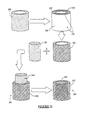
- FIG. 1 is a perspective detailed view of a scaffold according to various embodiments
- FIG. 2 is a perspective detailed view of a continuous phase composite according to various embodiments
- FIG. 3 is a graph comparing compressive strength over time of a continuous phase composite and a pure polymer sample according to various embodiments
- FIG. 4 is an implant according to various embodiments
- FIG. 5 is an implant according to various embodiments
- FIG. 6 is an implant according to various embodiments.
- FIG. 7 is an implant according to various embodiments.
- FIG. 8 is an implant according to various embodiments.
- FIG. 9 is an implant according to various embodiments.
- FIG. 10 is an implant according to various embodiments.
- FIG. 11 illustrates a method of forming an implant according to various embodiments
- FIG. 12 is a flow chart illustrating a method of selecting material for the forming of an implant according to various embodiments
- FIG. 13 is a cross-sectional view of an example of attaching an ACL in the tibia employing an implant according to various embodiments.
- FIG. 14 is a cross-sectional view of an example of a surgically reconstructed ACL employing an implant according to various embodiments.
- the word “include” and its variants is intended to be non-limiting, such that recitation of items in a list is not to the exclusion of other like items that may also be useful in the materials, compositions, devices, and methods of these teachings.
- the terms “a” and “an” mean at least one. Also, all compositional percentages are by weight of the total composition, unless otherwise specified.
- the present technology provides medical implants, in particular including implantable screws, comprising a bioabsorbable structure material having a plurality of interconnecting pores and bioresorbable polymer filling at least a portion of said plurality of interconnecting pores.
- FIGS. 4-10 and 13 - 14 depict representative medical implants. It is understood, however, that the present technology encompasses a wide variety of implants, used for a wide variety of therapeutic and cosmetic applications, in human or other animal subjects.
- the specific devices and materials used must, accordingly, be biomedically acceptable.
- a “biomedically acceptable” component is one that is suitable for use with humans or other animals without undue adverse side effects (such as toxicity, irritation, and allergic response) commensurate with a reasonable benefit/risk ratio.
- the structure 10 may be formed of natural sources of biocompatible, bioresorbable and/or bioabsorbable materials, such as coral.
- synthetic materials may be used to form the structure 10 . These materials may include absorbable ceramics, absorbable polymers, or any other absorbable porous matrix.
- the porous material may include the bioresorbable ceramic sold under the trade name Pro Osteon 500RTM by Interpore Spine Ltd. (Irvine, Calif., USA), Pro Osteon 200RTM by Interpore Spine Ltd.
- Porous materials useful herein include those disclosed in U.S. Pat. No. 4,976,736, White et al., issued Dec. 11, 1990; and U.S. Pat. No. 6,376,573 White et al, issued Apr. 23, 2002, which are hereby incorporated by reference.
- the Pro Osteon material consists of an interconnected or continuous porous calcium carbonate substrate with a thin surface layer of hydroxyapatite.
- Various other exemplary porous materials may include calcium carbonate, tricalcium phosphate, biphasic calcium phosphate, or any appropriate calcium based ceramic.
- the structure 10 may be any appropriate combination of materials, such as including one material as a coating on another.
- the structure 10 may be formed from a polymer.
- a polymer matrix may define a porous structure similar to the structure 10 .
- the material of the polymer matrix may be any appropriate polymer such as a biocompatible, bioresorbable and/or bioabsorbable polymer, including those discussed herein.
- the structure 10 may be formed of any appropriate material, including a resorbable ceramic, a polymer, a composite, and combinations thereof, etc.
- the structure 10 itself may be used for various purposes, such as a bone regeneration scaffold or bone graft replacement. Nevertheless, the physical properties of the structure 10 can be augmented for various reasons.
- the structure 10 alone may not include a selected physical property, such as a selected compressive strength, tensile strength, torsion strength, or the like.
- the structure 10 may be augmented to improve its properties allowing for greater use as a surgical device, as discussed herein in various embodiments.
- a second material 21 may be added thereto, such as during formation of the structure 10 itself or at a later time.
- the second material 21 may be injected into or otherwise provided into a plurality of pores 16 defined by the structure 10 .
- the structure 10 can include a channel or plurality of pores 16 that may be substantially continuous or interconnected pores 16 .
- the pores 16 may define a plurality of sizes of pores or porous structures.
- the pores 16 may range from about 0.1 nanometers (nm) to about 1 mm.
- the pores 16 may be any opening that allows access to the interior of the structure 10 .
- the pores 16 define a generally interconnected path throughout the structure 10 .
- the pores 16 may be connected with other pores 16 or channels to form the interconnected or continuous pores 16 or channels.
- the various channels may be interconnected such that more than a single channel or two openings may be interconnected in the structure 10 .
- the interconnected nature of the pores 16 may be referred to as a continuous phase throughout the structure 10 .
- the continuous phase may also be understood to be interconnected pores 16 that are defined by a solid portion of the structure 10 .
- the pores 16 generally extend through the structure 10 such that a path can be traced from a first side 10 a of the structure 10 to a second side 10 b of the structure, or from an entrance path to an exit path that can enter and exit from any sides, or from the same side.
- the different sized pores 16 or channels may be used with or are specifically applicable to different types of surgical indications.
- the pores 16 such as those generally ranging from about 10 nm to about 1 mm, may be filled with the second material 21 , which may be, for example, a selected polymer.
- Macroporosity as used herein, relates to the structure 10 comprising pores 16 with diameters about 100 ⁇ m or greater.
- Mesoporosity as used herein, relates to structure 10 comprising pores 16 with diameters that range from about 10 ⁇ m to about 100 ⁇ m.
- Microporosity as used herein, relates to the structure 10 comprising pores 16 with diameters from about 10 ⁇ m to less than 0.01 ⁇ m.
- structure 10 may comprise pores 16 that have macroporosity, mesoporosity, microporosity, or combinations thereof.
- structure 10 may comprise pores 16 having a diameter of about 190 microns to about 230 microns, and an exemplary structure 10 useful herein may be Pro Osteon 200RTM by Interpore Spine Ltd. (Irvine, Calif., USA).
- structure 10 may comprise pores 16 with diameters of about 350 microns to about 600 microns and an exemplary structure 10 may be Pro Osteon 500RTM by Interpore Spine Ltd. (Irvine, Calif., USA).
- the surface of pores 16 may comprise a coating 14 , and examples of coating 14 useful herein may include calcium sulfate, calcium carbonate, and/or calcium phosphate.
- the second material 21 may be injection molded in a semi-liquid, molten form to fill the macroporosity defined by the structure 10 , such as the pore 16 sizes that are operable or easily filled with the polymer in a flowable state.
- Various polymers may be used as the second material 21 to fill a selected porosity of the structure 10 .
- bioabsorbable, bioabsorbable, biocompatible materials, or any appropriate combination of materials may be used.
- Suitable absorbable materials useful for structure 10 may include, but are not limited to, glasses or ceramics comprising mono-, di-, tri-, ⁇ -tri-, ⁇ -tri-, and tetra-calcium phosphate, hydroxyapatite, calcium sulfates, calcium oxides, calcium carbonates, magnesium calcium phosphates, phosphate glass, bioglass, mixtures thereof or a stiff, strong polymer, such as a PLA polymer.
- the second material 21 may include PLA.
- PLA may be provided that includes a compositional ratio of about 70:30 poly(L/D,L lactic acid).
- the specific ratio of various chiral monomers in the polymer is merely exemplary and any appropriate ratio may be used.
- the 70:30 poly(L/D,L lactic acid) may be referred to as PLDLLA.
- Other polymers may include a copolymer of lactic acid and glycolic acid. It will be understood, however, that any appropriate polymer material may be used as the second material 21 to form the composite 20 .
- bioresorbable, biocompatible polymers include poly(glycolic acid), poly(carbonate), poly(urethane), poly(amino acids), poly(phosphazenes), poly(hydroxyacids), poly(anhydrides), poly(dioxanone), poly(hydroxybutyrate), and poly(caprolactone). Also, copolymers of these or other appropriate monomers may be used. Further, as discussed above, the structure 10 may be formed of a polymer matrix including these polymers or copolymers. The selected polymer that may be used with the structure 10 , however, may be injection molded or otherwise fill the pores 16 defined by the structure 10 . The second material 21 may fill the pores 16 of the structure 10 to form a substantially solid structure.
- the composite 20 may still include a selected porosity or open pores 16 or channels even when filled with the second material 21 . Also, it may be selected to fill the pores 16 less than completely, therefore, leaving an open space in at least a portion of the pores 16 even if they may include some of the second material 21 . For example, pores 16 having a size of about 0.01 ⁇ m to about 10 ⁇ m may still remain in the composite 20 after the second material 21 is injected for the second material 21 fills the larger pores 16 or macro pores of the structure 10 .
- the pores 16 that are generally less than about 10 ⁇ m may be referred to herein as micropores or microporosity. The microporosity, however, is not necessary and may not always be present.
- the microporosity may be substantially less or non-existent in the composite 20 .
- a polymer is generally formed of a single monomer while a copolymer generally includes at least two types of monomers.
- suitable materials useful for the second material. 21 include biocompatible polymers selected from the group consisting of aliphatic polyesters, polyorthoesters, polyanhydrides, polycarbonates, polyurethanes, polyamides, polyalkylene oxides, and combinations thereof.
- the second material 21 may be formed from aliphatic polymers, polyesters, copolymer polyesters and blends thereof. The aliphatic polyesters are typically synthesized in a ring opening polymerization.
- Suitable monomers include, but are not limited to, lactic acid, lactide (including L-, D-, meso and D,L mixtures), glycolic acid, glycolide, ⁇ -carprolactone, p-dioxanone (1,4-dioxan-2-one), trimethylene carbonate (1,3-dioxan-2-one), ⁇ -valerolactone, ⁇ -butyrolactone, ⁇ -decalactone, 2,5-diketomorpholine, pivalolactone, ⁇ , ⁇ -diethylpropiolactone, ethylene carbonate, ethylene oxalate, 3-methyl-1,4-dioxane-2,5-dione, 3,3-diethyl-1,4-dioxan-2,5-dione, gamma-butyrolactone, 1,4-dioxepan-2-one, 1,5-dioxepan-2-one, 6,6-dimethyl-dioxepan
- the composition of the implantable screw is selected to optimize one or more selected properties, such as a compressive strength after a selected time period after implantation, or the amount of time generally necessary for bone ingrowth to form a selected fusion. Therefore, a polymer may be chosen for the second material 21 of the composite 20 .
- the PLDLLA second material 21 discussed above, may form about 60% of the composite 20 with about 40% of the composite 20 being the structure 10 formed of the Pro Osteon 500R TM.
- Such a combination can achieve a compressive strength of about 1500 N to about 3000 N at about 6 months after implantation.
- other second materials 21 and other structures 10 may be used to achieve similar results or varying results to meet the needs of the composite 20 .
- a fast resorption of the composite 20 may be selected.
- healing or repair may be faster than in a fusion. Therefore, an interference screw that is substantially resorbed after about 3 months to about 6 months may be selected.
- Such an implant may be formed with a copolymer of lactic acid and glycolic acid.
- the copolymer can be about 85% lactic acid and about 15% glycolic acid, similar to the material sold as LacotsorbTM by Biomet, Inc.
- An implantable screw or implant, including such a copolymer can be about 60% of the composite 20 while the other about 40% is formed of the Pro Osteon may be used in a fracture situation.
- an implantable screw or implant ( 70 , 90 , 110 , 130 , 170 , 200 , 220 ) may be formed of such a composition for use as an interference screw in an ACL replacement procedure to provide a selected time when the graft is no longer held with the implant ( 70 , 90 , 110 , 130 , 170 , 200 , 220 ).
- the second material 21 may be a polymer, or a slower resorbing material and, as such, may be selected based upon inherent properties or ones formed therein.
- a slower resorbing second material 21 may generally be a polymer having a higher molecular weight.
- selected second materials 21 may include properties that may be achieved by a polymer having a lower molecular weight.
- selected strengths of the second material 21 may be inherent in a polymer itself, rather than a selected molecular weight thereof.
- the composite 20 can include a dual ceramic.
- the structure 10 can be formed of a first ceramic including a first property and the pores 16 or channels may be filled with a second ceramic (second material 21 ), rather than a polymer, and the second ceramic having a second property.
- the different properties can include resorption rates, compressive strengths, torsion strengths, or the like. This can be achieved by casting a ceramic slurry into the porosity of the structure 10 . The slurry can undergo a chemical reaction to set into a hardened form or it can be sintered to form a rigid ceramic phase.
- two polymers that independently may have different properties can be used to form the composite 20 .
- a first polymer having a first property
- the porosity of the structure 10 can be filled with the second material 21 (a second polymer) having a second property.
- the properties of the two polymers may include a compressive strength, a resorption rate, a tensile strength, or the like. This can be achieved through injection molding, in situ polymerization, and solution-casting techniques, as described herein.
- the composite 20 may be a substantially dual phase or greater composite 20 so that it will react in a substantially uniform manner when implanted in the body.
- the phases can refer to the phase of the structure 10 and the phase of the second material 21 positioned in the pores 16 or channels of the structure 10 , such as a bioresorbable polymer.
- the composite 20 may be about 30 weight percent (wt %) to about 70 wt % the second material 21 (a polymer fill) and about 30 wt % to about 70 wt % structure 10 .
- the composite 20 may be about 55 wt % to about 65 wt % the second material 21 (a polymer fill) and about 45 wt % to about 55 wt % ceramic structure 10 .
- the composite 20 may be substantially 100 wt % polymer if the structure 10 is formed from a porous polymer matrix.
- the composite 20 may be about 30 wt % to about 70 wt % the second material 21 (a polymer fill) and about 30 wt % to about 70 wt % structure 10 , a porous polymer matrix.
- Both phases may be substantially continuous.
- the second material 21 phase is substantially interconnected throughout the composite 20 and that structure 10 phase is also substantially interconnected.
- Such results can be obtained by using an intact structure 10 phase rather than a particle.
- an appropriate structure 10 phase may be formed from particles.
- the resulting composite 20 is effectively composed of two or more distinct, intact, and continuous phases.
- the different resorption rates of the continuous phases (for example, structure 10 and the second material 21 ) within the composite 20 results in a resorption profile that can include a slowly degrading phase and a quickly degrading phase.
- the quickly degrading phase can allow for tissue ingrowth as the phase is resorbed whereas the slowly degrading phase provides the implant site with mechanical support. It will be understood that either the structure 10 or the second material 21 may be formed to be the quicker resorbing phase.
- the composite 20 is the result of filling the pores 16 of structure 10 .
- the pores 16 of the structure 10 can be left open.
- the microporosity found in the structure 10 of composite 20 may, without being bound by the theory, function in that it allows for the absorption of fluid throughout the composite 20 and the diffusion of degradation products out of the composite 20 . This allows the composite 20 to degrade in an even manner from the inside out, results in a gradual transition of load to the newly regenerating tissue.
- acid based polymers such as PLA and PGA are used as the second material 21 within the composite 20
- the microporosity in the ceramic allows the acidic products to leave the implant and be absorbed by the surrounding tissue in a timely manner.
- the second material 21 injected into the structure 10 may fill the pores 16 of the structure 10 and yet maintain an open microporosity.
- the effect of this microporosity and/or continuous phase aspects of the composite 20 on the degradation of a continuous phase composite 20 is shown in FIG. 3 .
- the graph in FIG. 3 illustrates the results of an experiment where degradation was conducted in a generally known phosphate buffer solution held at about body temperature (about 37° C.)
- the degradation profile of a continuous phase composite 20 composed of PLDLLA (the second material 21 ) and Pro Osteon 500RTM (structure 10 ) was compared to a pure polymer sample composed of only PLDLLA.
- the graph of compressive strength over time shows a generally even and linear degradation profile of the composite 20 (line 30 ) when compared to a faster drop in strength seen with the pure polymer device (line 32 ).
- the graph clearly shows the impact of the composite 20 .
- the compressive strength of the pure PLDLLA sample does not change over a significant life span of the implant. Nevertheless, after about 150 days, a drop in compressive strength is illustrated. Therefore, during a majority of the life span of the PLDLLA implant, the compressive strength does not change, however, near the end of the life span of the PLDLLA implant, the compressive strength may degrade rapidly. A more even and linear drop in compressive strength may be selected for various applications. This may allow for an even and gradual loading of an area of the anatomy near the implant of the composite 20 .
- the compressive strength of the composite 20 is substantially linear over its lifetime.
- the degradation of the compressive strength of the composite 20 does not include any long periods of maintenance of a single strength, or a steep drop off at any particular time.
- a substantially linear decrease in compressive strength over time in the degradative environment, such as an anatomical environment, allows for the gradual loading of healing tissue with additional stresses.
- an implant when used as a bone replacement, it may be desirable to have a substantially continuous increase in stresses relative to the implant.
- the increase of stresses relative to the bone may increase or enhance bone ingrowth into the area.
- the composite 20 exhibits a linear decrease in compressive strength as shown FIG. 3 .
- the composite 20 also can be an excellent media for tissue ingrowth into the implant. This ability was demonstrated in a load-bearing bone defect model in the tibia and femur of sheep. In such a model, typical solid polymer implants may show bone formation in limited amounts on the surface of the material. With the continuous phase composite 20 , the resorption of the ceramic structure 10 phase may allow eventual growth of bone into the center of the implant wall.
- the interaction of calcium carbonate and lactic acid from the polymer (the second material 21 ) phase results in a self-neutralizing reaction that eliminates some of the acid released from a degrading implant. This phenomenon further improves the long term biocompatibility of the implant as seen by new bone formation in areas of active lactic acid degradation.
- tissue ingrowth in the pores 16 serves as a means to transport degradation products from the site to the bloodstream.
- the blood vessels within an implant and the pores 16 system allow degradation products to be cleared from the implant area in a timely manner.
- therapeutic agents are used in conjunction with the composite 20 .
- therapeutic agents which may be administered via the pharmaceutical compositions of the various embodiments include, without limitation: anti-infectives such as antibiotics and antiviral agents; chemotherapeutic agents (i.e. anticancer agents); anti-rejection agents; analgesics and analgesic combinations; anti-inflammatory agents; hormones such as steroids; growth factors, including bone morphogenic proteins (i.e. BMP's 1-7), bone morphogenic-like proteins (i.e. GFD-5, GFD-7 and GFD-8), epidermal growth factor (EGF), fibroblast growth factor (i.e.
- FGF 1-9) platelet derived growth factor (PDGF), insulin like growth factor (IGF-I and IGF-II), transforming growth factors (i.e. TGF- ⁇ I-III), vascular endothelial growth factor (VEGF); and other naturally derived or genetically engineered proteins, polysaccharides, glycoproteins, or lipoproteins.
- PDGF platelet derived growth factor
- IGF-I and IGF-II insulin like growth factor
- TGF- ⁇ I-III transforming growth factors
- VEGF vascular endothelial growth factor
- other naturally derived or genetically engineered proteins proteins, polysaccharides, glycoproteins, or lipoproteins.
- the composite 20 may comprise at least one of platelet rich plasma (PRP), concentrated bone marrow aspirate and lipoaspirate cells.
- the composite 20 may include hematopoietic stem cells, stromal stem cells, mesenchymal stem cells, endothelial progenitor cells, red blood cells, white blood cells, fibroblasts, reticulacytes, adipose cells, or endothelial cells. Any of the above cells, PRP, and/or concentrated bone marrow aspirate may be obtained by using centrifugation methods and an example of such methods is disclosed in U.S. Patent Application Publication No. 2005/0109716.
- composite may be soaked in at least one fraction created by centrifugation.
- the at least one fraction may include at least one of PRP, concentrated bone marrow aspirate, lipoaspirate cells, hematopoietic stem cells, stromal stem cells, mesenchymal stem cells, endothelial progenitor cells, red blood cells, white blood cells, fibroblasts, reticulacytes, adipose cells, endothelial cells, any other autologous tissue, and combinations thereof.
- the composite 20 comprises concentrated bone marrow aspirate made by a method for concentrating bone marrow aspirate and blood including collecting bone marrow aspirate and blood from a patient then loading the bone marrow aspirate and blood into a separator that can separate the aspirate and the blood into three or more fractions.
- the method includes centrifuging the separator containing the bone marrow aspirate and the blood creating a fraction that has a concentrated bone marrow aspirate and/or a concentrated blood.
- a concentration may be referred to as a buffy coat.
- the method also includes withdrawing the fraction comprising the concentrate or buffy coat.
- the composite 20 comprises concentrated bone marrow aspirate, blood, and/or a blood fraction.
- Such materials may be derived by loading bone marrow aspirate and/or blood into a separator that can separate the bone marrow aspirate and/or blood into three or more fractions.
- the method also includes centrifuging the separator then withdrawing a fraction comprising at least one of the group consisting of buffy coat, hematopoietic stem cells, stromal stem cells, mesenchymal stem cells, endothelial progenitor cells, red blood cells, white blood cells, fibroblasts, reticulacytes, adipose cells, and endothelial cells, and then applying the fraction to an implant according to this technology, and implanting the implant.
- a fraction comprising at least one of the group consisting of buffy coat, hematopoietic stem cells, stromal stem cells, mesenchymal stem cells, endothelial progenitor cells, red blood cells, white blood cells, fibroblasts, reticulacytes, adipose cells, and endothelial cells
- the composite 20 may also be formed by using any appropriate method, including such methods as are known to those skilled in the art.
- the second material 21 used to fill the selected porosity is added to the structure 10 or otherwise used to fill the porosity of the structure 10 .
- injection molding is used to force molten polymer (the second material 21 ) into the macroporosity of a porous ceramic structure 10 . This can result in the composite 20 including approximately 5-10% open microporosity.
- vacuum impregnation techniques may be used.
- a relatively low pressure is formed in the structure 10 to pull the second material 21 , which may be, for example, a bioresorbable polymer or a combination thereof, into the porosity.
- Further techniques include solution embedding where the second material 21 is dissolved and then cast into the porosity.
- in situ polymerization techniques where the polymer being used as second material 21 may be polymerized within the porosity of the structure 10 can be used to form the composite 20 .
- the structure 10 is submerged in a reaction mixture of a monomer or a plurality of monomers, an initiator, and/or a catalyst and then heated to the reaction temperature.
- the second material 21 (a polymer) is then formed in situ within the porosity of the structure 10 .
- a porous polymer matrix as the structure 10 .
- the ceramic material is cast within a porous, polymer matrix structure that forms the structure 10 .
- a polymer matrix may be formed to include a selected porosity and a ceramic slurry may be positioned in the pores of the matrix. The ceramic slurry may then be forced to harden to form a solid or porous ceramic phase within the porosity of the structure 10 .
- the composite 20 may be formed by positioning the polymer in the structure 10 formed of a porous ceramic or by positioning a ceramic in the structure 10 formed of a porous polymer.
- implant 70 may be an interference screw that can be used to attach soft tissue to bone such as for ligament repair or replacement, as described herein.
- the implant 70 demonstrates the versatility of the fabrication process by machining devices with both a composite portion 74 which may be composite 20 and a polymer portion 76 which may be the second material 21 or another bioresorbable polymer.
- the implant 70 may include an external thread or engagement portion 72 composed of the composite portion 74 similar to the composite 20 .
- implant 70 can be machined from a composite 20 block with an excess polymer portion 76 . This results in a dual region implant 70 with a polymer portion 76 and a composite portion 74 .
- the composite portion 74 may be formed from a ceramic material (structure 10 ), such as the Pro Osteon 500RTM, that has been reinforced or injected with a polymer (the second material 21 ), such as the PLDLLA. Also, the polymer portion 76 may be molded to the composite portion 74 according to various embodiments.
- the polymer portion 76 may be composed of 100% PLDLLA. Such a polymer portion 76 can improve the mechanical properties of the implant 70 for various applications.
- the polymer portion 76 may provide a torsional strength that is greater than the torsional strength of the composite portion 74 . Therefore, a tool engaging portion 78 or area may be formed in the polymer portion 76 to allow for a greater torsional force to be applied to the implant 70 by a driver that may not be satisfied by the composite portion 74 .
- the tool engagement portion 78 may include a hexagonal (hex or Allen), a slot, a square, a tapered square (Robertson), an oval, a cruciform shape, a star (Torx®), a cross (Philips), or the like, that is an open shape through at least a portion of the center of the implant 70 .
- a driver (not shown) is designed to engage with one of the above mentioned open shapes to transfer torque needed to screw implant 70 into a bone tunnel.
- this orientation of polymer portion 76 and composite portion 74 can be fabricated by drilling holes within the porous structure 10 and then subjecting the structure 10 to one of the composite fabrication techniques to introduce the second material 21 into the pores 16 of structure 10 , as discussed above.
- the addition of the second material 21 phase to the structure 10 with pores 16 results in the filling of the pores 16 in addition to creating the composite 20 .
- the implant 70 can be centered around a defined bore 80 through the implant 70 .
- the resulting implant 70 will have a polymer portion 76 on top of composite portion 74 .
- implant 90 may be an interference screw that can be used to attach soft tissue to bone, such as for ligament repair or replacement, as described herein.
- the implant 90 can also include two regions, such as a composite region 92 , which may be composite 20 , and a polymer portion 94 , which may be the second material 21 or another bioresorbable polymer.
- the composite region 92 may be substantially similar to the composite 20 illustrated in FIG. 2 .
- the addition of the polymer portion 94 to the central area of the composite portion 92 can be used to achieve selected properties of the implant 90 .
- the polymer region 94 may provide a torsional strength that is greater than the torsional strength of the composite portion 92 . Therefore, a tool engaging portion 100 or area may be formed in the polymer portion 94 to allow for a greater torsional force to be applied to the implant 90 by a driver (not shown) that may not be satisfied by the composite portion 92 .
- the tool engagement portion 100 may include a hexagonal (hex or Allen), a slot, a square, a tapered square (Robertson), an oval, a cruciform shape, a star (Torx®), a cross (Philips), or the like, that is an open shape through at least a portion of the center of the implant 90 .
- a driver (not shown) is designed to engage with one of the above mentioned open shapes to transfer torque needed to screw implant 90 into a bone tunnel.
- this orientation of polymer portion 94 and composite portion 92 can be fabricated by drilling holes within the porous structure 10 and then subjecting the structure 10 to one of the composite fabrication techniques to introduce the second material 21 into the pores 16 of structure 10 , as discussed above.
- the addition of the second material 21 phase to the structure 10 with pores 16 results in the filling of the pores 16 in addition to creating the composite 20 .
- the implant 90 can be centered around the central polymer portion 94 to define a bore 96 through the implant 90 .
- the resulting implant 90 will have a central polymer portion 94 surrounded by a composite portion 92 .
- the implant 90 may be used for any appropriate purpose, and an engagement portion 98 may be formed on an exterior thereof.
- the engagement portion 98 may be used to engage various structures, such as bone, such that the implant 90 may be an anchor or may define a screw.
- a tool engagement portion 100 may be defined in the central polymer portion 94 for allowing engagement of a tool or driver (not shown) with the implant 90 for positioning the implant 90 in various anatomical locations.
- the implant 90 may be used as a bone anchor, a suture anchor, a soft tissue anchor, a fracture screw, an interference screw, or any appropriate purpose.
- implant 110 may be an interference screw that can be used to attach soft tissue to bone such as for ligament repair or replacement, as described herein.
- the implant 110 demonstrates the versatility of the fabrication process by machining devices with both a composite portion 112 which may be composite 20 and a polymer portion 114 which may be the second material 21 or another bioresorbable polymer.
- the implant 110 may include an external thread or engagement portion 118 composed of a continuous phase composite that may be similar to the composite 20 .
- implant 110 can be machined from a composite 20 block with an excess polymer portion 114 . This results in a dual region implant with a polymer portion 114 and a composite portion 112 .
- the composite portion 112 may be formed from a ceramic material (structure 10 ), such as the Pro Osteon 500RTM, that has been reinforced or injected with a polymer (the second material 21 ), such as the PLDLLA. Also, the polymer portion 114 may be molded to the composite portion 112 , according to various embodiments.
- the polymer portion 114 may be composed of 100% PLDLLA. Such a polymer portion 114 can improve the mechanical properties of the implant 110 for various applications.
- the polymer portion 114 may provide a torsional strength that is greater than the torsional strength of the composite portion 112 . Therefore, a tool engagement portion 116 or area may be formed in the polymer portion 114 to allow for a greater torsional force to be applied to the implant 110 by a driver that may not be satisfied by the composite portion 112 .
- the tool engagement portion 116 may include a hexagonal (hex or Allen), a slot, a square, a tapered square (Robertson), an oval, a cruciform shape, a star (Torx®), a cross (Philips), or the like, that is an open shape through at least a portion of the center of the implant 110 .
- a driver (not shown) is designed to engage with one of the above mentioned open shapes to transfer torque needed to screw implant 110 into a bone tunnel.
- this orientation of polymer portion 114 and composite portion 112 can be fabricated by drilling holes within the porous structure 10 and then subjecting the structure 10 to one of the composite fabrication techniques to introduce the second material 21 into the pores 16 of structure 10 , as discussed above.
- the addition of the second material 21 phase to the structure 10 with pores 16 results in the filling of the pores 16 in addition to creating the composite 20 .
- the implant 110 can be centered around the central tool engagement portion 116 to define a bore 80 through the implant 110 .
- the resulting implant 110 will have a central polymer portion 114 surrounded by a composite portion 112 .
- implant 130 may be an interference screw that can be used to attach soft tissue to bone, such as for ligament repair or replacement as described herein.
- the implant 130 can be made as a composite portion 132 , which may be composite 20 .
- the composite portion 132 may be substantially similar to the composite 20 illustrated in FIG. 2 . Therefore, a tool engaging portion 140 or area may be formed in the composite portion 132 to allow for a torsional force to be applied to the implant 130 by a driver.
- the tool engagement portion 140 may include a hexagonal (hex or Allen), a slot, a square, a tapered square (Robertson), an oval, a cruciform shape, a star (Torx®), a cross (Philips), or the like, that is an open shape through at least a portion of the center of the implant 130 .
- a driver (not shown) is designed to engage with one of the above mentioned open shapes to transfer torque needed to screw implant 130 into a bone tunnel.
- Implant 130 can be fabricated by drilling holes within the porous structure 10 and then subjecting the structure 10 to one of the composite fabrication techniques to introduce the second material 21 into the pores 16 of structure 10 , as discussed above.
- the addition of the second material 21 phase to the structure 10 with pores 16 results in the filling of the pores 16 in addition to creating the composite 20 .
- the implant 130 can be centered around the central tool engagement portion 140 to define a bore 136 through the implant 130 .
- the resulting implant 130 will have a tool engagement portion 140 surrounded by a composite portion 132 .
- the implant 130 may be used for any appropriate purpose, and an engagement portion 138 may be formed on an exterior thereof.
- the engagement portion 138 may be used to engage various structures, such as bone, such that the implant 130 may be an anchor or may define a screw.
- a tool engagement portion 140 may be defined in the composite portion 132 for allowing engagement of a tool with the implant 130 for positioning the implant 130 in various anatomical locations.
- the implant 130 may be used as a bone anchor, a suture anchor, a soft tissue anchor, a fracture screw, an interference screw, or any appropriate purpose.
- interference screws such as implant 70 , 90 , 110 , 130 may be sized so that they are slightly larger that the diameter of the tunnel, so that they dilate the bone tunnel upon insertion. Dilation advantageously compacts the soft cancellous bone between the ends of the tunnel, providing better fixation.
- Conventional straight-sided bioabsorbable interference screws have an interference fit of about 1 mm such that about 1 mm of bone is dilated as the screw is inserted into the bone tunnel.
- Implants such as the implants 70 , 90 , 110 , 130 , may be formed in many different ways and include different structures. Those described above are merely exemplary in nature and not intended to limit the present teachings herein.
- an implant 70 , 90 , 110 , 130 may include an exterior thin coat formed around a polymer interior, or vice-versa.
- the exterior thin coat may include a thickness that is substantially less than that of the interior portion, but provide selected properties to an implant.
- the implant 170 may define a screw or anchor portion that may be positioned relative to a selected portion of the anatomy.
- the implant 170 may define a thread 172 that extends along a length of the implant 170 from a first or insertion end 174 to a second or driving end 176 .
- the thread 172 may or may not extend the entire length of the implant 170 .
- the implant 170 may define the thread 172 and the driving end 176 such that the implant 170 may be inserted into a selected portion of the anatomy. Similar to the implants 70 , 90 , 110 , 130 illustrated in FIGS. 4-7 above, the implant 170 may be used to fix a selected soft tissue therein, fix a structure thereto, or other appropriate procedures. For example, in a generally known anterior cruciate ligament replacement, the implant 170 may define an interference screw to assist in holding the graft in a selected position.
- the implant 170 may be formed substantially completely of the composite 20 . It will be understood that the implant 170 or the implants described above, according to various embodiments, may be provided for various procedures or purposes. As is generally understood in the art, a graft may be positioned or provided of soft tissue to interconnect a femur and a tibia. The implant 170 may be used to substantially hold the soft tissue portion relative to a selected portion of the anatomy. As discussed above, the composite material forming the implant 170 may be absorbed into the anatomy at a selected rate to allow for bone ingrowth and fixation, such as generally anatomical fixation, of the soft tissue may be provided. In various embodiments, implant 170 may comprise a composite region and a polymer region, as well as tool engagement, as illustrated and described above in FIGS. 4-7 .
- implant 200 in FIG. 9 can be used for fracture repair.
- implant 200 may be used as an interference screw in ligament repair or replacement, as described herein.
- the implant 200 may include an extended shaft that defines a thread 202 along all or a portion of the shaft.
- a driving end 204 may also be provided to assist in driving the implant 200 into the selected implant site.
- the thread 202 defined by the implant 200 may be driven into a pre-formed bore, a tapped bore, an untapped bore, or any predefined void.
- the implant 200 may be formed in appropriate dimensions, such as a length, thickness, thread height, etc., to achieve selected results.
- the implant 200 may also be cannulated and have a similar composition and tool engagement to the dual region implant 70 , 90 , 110 and 130 as illustrated and described above in FIGS. 4-7 .
- the implant 220 may include a suture anchor or define a suture anchor to assist in holding a selected suture 222 used in soft tissue repair.
- the suture 222 may be to reattach a soft tissue region to bone or other soft tissue.
- implant 220 may be used as an interference screw in ligament repair or replacements as described herein.
- the implant 220 may define a shaft or body including a first end 224 and a second end 226 .
- the body of the implant 220 may further have a first engaging or interference portion 228 extending therefore.
- a second interference portion 230 may also be provided.
- the implant 220 may then be driven into the bone of the soft tissue fixation site.
- the suture 222 is then used to affix the soft tissue to bone.
- the implant 220 may be generally driven into a bore formed in the portion of the anatomy including a diameter less than a diameter or dimension of the interference portions 228 , 230 . Therefore, the implant 220 may form an interference fit with a selected portion of the anatomy to hold the suture 222 relative to the selected portion of the anatomy.
- the implant 220 may also be cannulated and have a similar composition and tool engagement to the dual region implant 70 , 90 , 110 and 130 as illustrated and described above in FIGS. 4-7 .
- an implant 350 may be formed according to the illustrated method 351 .
- a blank 356 may be formed of the structure 10 .
- the structure 10 may be any appropriate porous material, such as a polymer matrix, ceramic, or the like.
- the blank 356 may also be shaped into any appropriate geometry, such as a cylinder.
- the blank 356 may then be injected with the second material 21 , such as a polymer, as discussed above. This may create polymer portions 358 that extend from a composite 352 that may be similar to the composite 20 .
- the injection may occur by melting the second material 21 and injecting it under pressure into the pores 16 and/or channels defined by the blank 356 .
- the composite 352 may then have the exterior polymer portions 358 removed to include substantially only the composite 352 .
- a fill material 354 such as, for example, polymer, may then be inserted into the composite 352 form.
- the fill material 354 may be any appropriate material.
- the fill material 354 may be substantially similar to the material that formed the blank 356 .
- the two portions, including the fill material 354 and the composite 352 may then be heated to meld the two together to form the implant 350 .
- the fill material 354 may be formed into the implant 350 and provided complete for a procedure.
- implant 350 may be formed to include voids or pre-filled voids.
- the fill material 354 may serve the same purpose as the graft material discussed above, such as a void filling or support purposes. Nevertheless, the implant 350 may include the fill material 354 and be manufactured with the fill material 354 .
- a flow chart describes a method 400 for forming an implant according to various embodiments.
- the method 400 may begin at a start block 401 .
- a selected implant region is selected in block 402 .
- the implant region may be any appropriate region of the anatomy.
- a spinal region, a tibial region, a femoral region, a humeral region, or the like may be selected.
- an implant may be formed for any appropriate portion of the anatomy using the composite 20 .
- loads may be determined relative to that the region in block 404 .
- a compressive force, shear force, torsion force, or the like may be determined at the selected region of the anatomy. For example, it may be determined that about 1500 N to about 3000 N may be experienced in a spinal region.
- forces may depend upon a patient, the region selected, and other considerations.
- a torsion stress necessary for implantation may be determined.
- properties of an implant may then be determined in block 406 .
- the loads determined in the anatomical region may be different than those determined as a property of the implant in block 406 , but they may be related.
- a selected resorption time may be a property selected in block 406 .
- a resorption time of the implant may depend upon selected loads in the region of the anatomy or ingrowth rates at the selected regions, or other selected reasons.
- the resorption time or profile of the implant may be determined in block 406 .
- bond ingrowth in various regions of the body may vary depending on the region, loads encountered and anatomical condition of the area of interest.
- implant materials may be determined in block 408 .
- the materials selected may be the appropriate material to form the structure 10 or the appropriate second material 21 for the fill of the pores 16 .
- both the structure 10 and the fill for the pores 16 can be polymers or both can be ceramic materials.
- the implant materials may be selected to achieve the selected properties, such as a strength, strength degradation profile, resorption profile, load-bearing, etc.
- the materials selected may be a second material 21 of a selected molecular weight, a certain co-polymer, etc.
- the configuration or form of the implant can be determined when determining the implant materials in block 408 , or at any appropriate time.
- the implant may include a composite portion (such as composite 20 ) and a noncomposite portion (such as second material 21 ). Therefore, to achieve the determined properties of the implant, such designs may also be determined in block 408 .
- the implant can be formed in block 410 .
- the implant may be formed of the materials determined in block 408 and the configuration determined in block 408 .
- the implant may be formed according to any appropriate method and the formation method may also be chosen depending upon a selected property. For example, the second material 21 may be melted and then injected into the porous structure 10 . Nevertheless, any appropriate method may be used to form the implant in block 410 .
- the implant formed in block 410 may then be implanted in block 412 .
- the implant may be customized by a user prior to implantation or it may be implanted as formed in block 410 .
- a graft material may be used with the implant formed in block 410 , also as discussed above.
- the implant is formed in block 410 , it can be implanted in block 412 .
- the method 400 ends in block 414 .
- the method 400 is merely exemplary and an implant may be formed of the composite 20 according to any appropriate method.
- the implant formed according to method 400 can include a selected property to achieve selected results after implantation.
- the selected properties can be achieved by selecting appropriate materials for the composite implant, a selected configuration of the implant, or other appropriate considerations.
- the composite 20 may be used to form an implant that includes a selected strength over a selected period of time, yet can still allow ingrowth of bone.
- the composite 20 may be formed into an implant where bone may grow into regions that are faster resorbing than other regions. This may be created by including the faster resorbing phase and the slower resorbing phase.
- the difference in resorption rates may be any appropriate difference, such as about 10% different to about 200% different.
- the slower resorbing phase may be selected for a strength quality to achieve a selected strength degradation profile, while the faster responding phase may be selected based upon the bone regrowth rate of the area of interest. This can assist in bone regrowth and in allowing recovery when a resorption may be selected in a load-bearing area of the anatomy. This may also be used to achieve a selected strength of the implant for a selected period for any appropriate purpose.
- the method 400 can be used to select materials and properties of the materials for a selected or unique application.
- the known or determined bone growth rate of a selected region of the anatomy can be used to assist in determining the materials to be used in forming the implant, the ratios of the materials to be used, or the specific properties of the materials to be used.
- the forces that are experienced in a selected region of the anatomy may be used to select the materials to be used to form an implant. Thus, a higher selected strength may be used to select different materials for forming the implant. Therefore, the method 400 may be used to select materials for an implant, select a structure of an implant, or selected other features of the implant.
- the present technology provides methods of using the implants or implantable screws disclosed herein for tissue repair, including ligament repair procedures.
- the ACL and PCL procedures may be performed arthroscopically and, generally, involve preparing a bone tunnel through the tibia and adjacent femur, placing a ligament graft extending between the two bone tunnels, and securing each end of the graft within its respective tunnel.
- ACL reconstruction employs the use of bone-tendon-bone ligament grafts bone ligament grafts (harvested from the patella and tibia) where the bone block at each end of the graft is fixed within its respective tunnel by an implantable interference screw secured within each tunnel between the tunnel wall and the adjacent bone block.
- the interference screw is aligned parallel to the axis of the tunnel and holds the bone block in the tunnel by wedging it against the tunnel wall opposite the interference screw and by engaging the bone block and the adjacent tunnel wall with the interference screw threads.
- Another common method employs the use of soft tissue grafts (semitendinosus, hamstring, Achilles, quadriceps, etc.) where the ends of the graft are secured by an interference screw similarly interposed between the wall of the bone tunnel and the adjacent soft tissue of the graft.
- a widely used technique for the reconstruction of the ACL is known as the Jones procedure.
- the basic steps in the procedure include harvesting a graft made from a portion of the patellar tendon with attached bone blocks; preparing the graft attachment site by drilling holes in opposing bones of the joint in which the graft will be placed; placing the graft in the graft attachment site; and rigidly fixing the bone blocks in place within the graft site, in the holes or bone tunnels.
- the interference screws used to fix the graft in place are wedged between the bone block and the wall of the hole into which the bone block fits. Typically, there is very little space between the bone block and the hole in the bone at the fixation site. See, for example, U.S. Pat. Nos.
- Substitute ligament 206 may be an audiograph, such as a patellar tendon, a portion of a patellar tendon harvested from a patient, or may be a ligament or a tendon harvested from another part of the patient's body such as from a hamstring, an Achilles tendon, or the fascia lata.
- the substitute ligament 206 may be synthetic.
- a hole or a first tunnel 203 is drilled in the femur 208 .
- a second tunnel 218 is drilled in the tibia 208 .
- the substitute ligament 206 may be bundled and sutures 212 , 213 are added at either end using a guide wire in suture 204 , the substitute ligament 206 is pulled through the second tunnel 218 and the through the first tunnel 203 .
- Tunnels 203 , 218 may be bore using a drill bit and may employ additional tools such as a tubular tunnel guide and a dilation tool, to create a proper hole in a proper position. Tunnels 203 , 218 may be started using a pilot tool.
- the first interference screw 201 is driven using driver 219 .
- tension tool 215 pulls suture 212 with a known force 214 .
- known force 214 may be between about 50 N and about 100 N.
- the second interference screw 209 is driven into the second tunnel 218 .
- the second interference screw 209 may be driven into femur 208 using a guide 207 to ensure that it has been driven into femur 208 correctly.
- the second interference screw 209 engages the wall of second tunnel 218 and the substitute ligament 206 such that the substitute ligament 206 is affixed and secure within femur 208 .
- substitute ligament 206 may include bone block at either end of the substitute ligament 206 such that the interference screws ( 201 , 209 ) engage the bone block and the wall of the tunnel.
- interference screws 201 , 209 may be any of the interference screws 70 , 90 , 110 , 130 , 170 , 200 , 220 and their equivalents, as described above.
- interference screws 201 , 209 may be comprise autologous tissue which may include at least one of platelet rich plasma, concentrated bone marrow, and lipoaspirate cells.
- therapeutic agents are used in conjunction with the interference screws 201 , 209 .
- therapeutic agents which may be administered in various embodiments include, without limitation, anti-infectives such as antibiotics and antiviral agents; chemotherapeutic agents (i.e. anticancer agents); anti-rejection agents; analgesics and analgesic combinations; anti-inflammatory agents; hormones such as steroids; growth factors, including bone morphogenic proteins (i.e. BMP's 1-7), bone morphogenic-like proteins (i.e. GFD-5, GFD-7 and GFD-8), epidermal growth factor (EGF), fibroblast growth factor (i.e.
- FGF 1-9) platelet derived growth factor (PDGF), insulin like growth factor (IGF-I and IGF-II), transforming growth factors (i.e. TGF- ⁇ I-III), vascular endothelial growth factor (VEGF); and other naturally derived or genetically engineered proteins, polysaccharides, glycoproteins, or lipoproteins.
- PDGF platelet derived growth factor
- IGF-I and IGF-II insulin like growth factor
- TGF- ⁇ I-III transforming growth factors
- VEGF vascular endothelial growth factor
- other naturally derived or genetically engineered proteins proteins, polysaccharides, glycoproteins, or lipoproteins.
- interference screws 201 , 209 may comprise at least one of platelet rich plasma (PRP), concentrated bone marrow aspirate, and lipoaspirate cells.
- interference screws 201 , 209 may comprise at least one of hematopoietic stem cells, stromal stem cells, mesenchymal stem cells, endothelial progenitor cells, red blood cells, white blood cells, fibroblasts, reticulacytes, adipose cells, or endothelial cells. Any of the above cells, PRP, and/or concentrated bone marrow aspirate may be obtained by using centrifugation methods and an example of such methods is disclosed in U.S. Patent Application Publication No. 2005/0109716.
- composite may be soaked in at least one fraction created by centrifugation.
- the at least one fraction may include at least one of PRP, concentrated bone marrow aspirate, lipoaspirate cells, hematopoietic stem cells, stromal stem cells, mesenchymal stem cells, endothelial progenitor cells, red blood cells, white blood cells, fibroblasts, reticulacytes, adipose cells, endothelial cells, any other autologous tissue and combinations thereof.
- interference screw 201 , 209 comprise concentrated bone marrow aspirate made by a method for concentrating bone marrow aspirate and blood, including collecting bone marrow aspirate and blood from a patient, then loading the bone marrow aspirate and/or blood into a separator that can separate the bone marrow aspirate and/or blood into three or more fractions.
- the method includes centrifuging the separator containing the bone marrow aspirate and the blood creating a fraction that has a concentrated bone marrow aspirate and/or a concentrated blood component.
- a concentration may be a buffy coat.
- the method also includes withdrawing the fraction comprising the concentrate or buffy coat.
- interference screw 201 , 209 comprises concentrated bone marrow aspirate and/or blood, or a blood fraction.
- Such materials may be derived by loading bone marrow aspirate and/or blood into a separator that can separate the bone marrow aspirate and/or blood into three or more fractions.
- the method also includes centrifuging the separator then withdrawing a fraction comprising at least one of the group consisting of buffy coat, hematopoietic stem cells, stromal stem cells, mesenchymal stem cells, endothelial progenitor cells, red blood cells, white blood cells, fibroblasts, reticulacytes, adipose cells, and endothelial cells, then applying the fraction to an implant according to disclosure, and implanting the implant.
- a fraction comprising at least one of the group consisting of buffy coat, hematopoietic stem cells, stromal stem cells, mesenchymal stem cells, endothelial progenitor cells, red blood cells, white blood cells, fibroblasts, reticulacytes, adipose cells, and endothelial cells
- a kit may include at least one interference screw such as those interferences screws described herein and, more specifically, interference screws 70 , 90 , 110 , 130 , 170 , 200 , 220 ; and a driver operable to drive the screw into a tunnel in a patient's bone.
- the kit of the interference screw comprises a tool engagement area that cooperates with the driver.
- the total engagement area may have a cross-sectional area of a hexagonal (hex or Allen), a slot, a square, a tapered square (Robertson), an oval, a cruciform shape, a star (Torx®), or a cross (Philips).
- the kit further comprises at least one of a drill bit, a dilator, a tibia tunnel guide, a modular guide, a graft prep table, bone coring instrument, a tibial reamer, an imprigment rod, a femoral aimer, an acorn reamer, a washer, a top, a guide wire, a dilator, a pull-through suture, and a pilot hole tool.
- a drill bit a dilator, a tibia tunnel guide, a modular guide, a graft prep table, bone coring instrument, a tibial reamer, an imprigment rod, a femoral aimer, an acorn reamer, a washer, a top, a guide wire, a dilator, a pull-through suture, and a pilot hole tool.
Abstract
Description
Claims (29)
Priority Applications (2)
| Application Number | Priority Date | Filing Date | Title |
|---|---|---|---|
| US11/702,448 US8535357B2 (en) | 2004-12-09 | 2007-02-05 | Continuous phase compositions for ACL repair |
| US13/956,948 US9211184B2 (en) | 2004-12-09 | 2013-08-01 | Continuous phase compositions for ACL repair |
Applications Claiming Priority (2)
| Application Number | Priority Date | Filing Date | Title |
|---|---|---|---|
| US11/008,075 US7879109B2 (en) | 2004-12-08 | 2004-12-09 | Continuous phase composite for musculoskeletal repair |
| US11/702,448 US8535357B2 (en) | 2004-12-09 | 2007-02-05 | Continuous phase compositions for ACL repair |
Related Parent Applications (1)
| Application Number | Title | Priority Date | Filing Date |
|---|---|---|---|
| US11/008,075 Continuation-In-Part US7879109B2 (en) | 2004-12-08 | 2004-12-09 | Continuous phase composite for musculoskeletal repair |
Related Child Applications (1)
| Application Number | Title | Priority Date | Filing Date |
|---|---|---|---|
| US13/956,948 Division US9211184B2 (en) | 2004-12-09 | 2013-08-01 | Continuous phase compositions for ACL repair |
Publications (2)
| Publication Number | Publication Date |
|---|---|
| US20070141110A1 US20070141110A1 (en) | 2007-06-21 |
| US8535357B2 true US8535357B2 (en) | 2013-09-17 |
Family
ID=38173833
Family Applications (2)
| Application Number | Title | Priority Date | Filing Date |
|---|---|---|---|
| US11/702,448 Active 2029-06-25 US8535357B2 (en) | 2004-12-09 | 2007-02-05 | Continuous phase compositions for ACL repair |
| US13/956,948 Expired - Fee Related US9211184B2 (en) | 2004-12-09 | 2013-08-01 | Continuous phase compositions for ACL repair |
Family Applications After (1)
| Application Number | Title | Priority Date | Filing Date |
|---|---|---|---|
| US13/956,948 Expired - Fee Related US9211184B2 (en) | 2004-12-09 | 2013-08-01 | Continuous phase compositions for ACL repair |
Country Status (1)
| Country | Link |
|---|---|
| US (2) | US8535357B2 (en) |
Cited By (15)
| Publication number | Priority date | Publication date | Assignee | Title |
|---|---|---|---|---|
| US20140052060A1 (en) * | 2012-08-15 | 2014-02-20 | Synthes Usa, Llc | Drug Eluting Surgical Screw |
| US20140236196A1 (en) * | 2006-07-18 | 2014-08-21 | Davol, Inc. (a C.R. Bard Company) | Method and apparatus for surgical fastening |
| US20150148906A1 (en) * | 2013-11-27 | 2015-05-28 | Coalign Innovations, Inc. | Structurally supporting insert for spinal fusion cage |
| US20150150614A1 (en) * | 2013-11-26 | 2015-06-04 | National Taiwan University Hospital | Bionic fixing apparatus |
| US20150245854A1 (en) * | 2006-11-17 | 2015-09-03 | Wake Forest University Health Sciences | External fixation assembly and method of use |
| US9456905B2 (en) | 2004-12-08 | 2016-10-04 | Biomet Manufacturing, Llc | Continuous phase composite for musculoskeletal repair |
| US20160310186A1 (en) * | 2015-04-24 | 2016-10-27 | Biomet Sports Medicine, Llc | Porous implants with injectable capabilities |
| US10064737B2 (en) | 2015-12-07 | 2018-09-04 | Industrial Technology Research Institute | Implant device for osseous integration |
| US10420597B2 (en) | 2014-12-16 | 2019-09-24 | Arthrex, Inc. | Surgical implant with porous region |
| US10426626B2 (en) | 2016-05-03 | 2019-10-01 | Additive Orthopaedics, LLC. | Bone fixation device and method of use |
| US10507041B2 (en) | 2013-11-26 | 2019-12-17 | Industrial Technology Research Institute | Bionic fixing apparatus and apparatus for pulling out the same |
| US11058468B2 (en) | 2016-07-29 | 2021-07-13 | Additive Orthopaedics, LLC | Bone fixation device and method of use |
| US11147679B2 (en) | 2018-02-05 | 2021-10-19 | Paragon Advanced Technologies, Inc. | Bone fixation device |
| US11457912B2 (en) | 2016-06-02 | 2022-10-04 | Parcus Medical, Llc | Suture tool and method of use |
| US11478286B2 (en) | 2016-06-03 | 2022-10-25 | Paragon Advanced Technologies, Inc. | Bone fixation devices |
Families Citing this family (27)
| Publication number | Priority date | Publication date | Assignee | Title |
|---|---|---|---|---|
| US8535357B2 (en) | 2004-12-09 | 2013-09-17 | Biomet Sports Medicine, Llc | Continuous phase compositions for ACL repair |
| EP2214565A4 (en) | 2007-10-27 | 2015-08-26 | Parcus Medical Llc | Suture anchor |
| ES2647919T3 (en) * | 2008-08-13 | 2017-12-27 | Smed-Ta/Td, Llc | Drug supply implants |
| CA2779109A1 (en) | 2009-10-29 | 2011-05-05 | Prosidyan, Inc. | Dynamic bioactive bone graft material having an engineered porosity |
| EP2493424A4 (en) * | 2009-10-29 | 2014-04-30 | Prosidyan Inc | Bone graft material |
| EP2493425B1 (en) * | 2009-10-29 | 2016-10-05 | Prosidyan, Inc. | Dynamic bioactive bone graft material and methods for handling |
| US8883195B2 (en) | 2013-03-14 | 2014-11-11 | Prosidyan, Inc. | Bioactive porous bone graft implants |
| US8889178B2 (en) | 2013-03-14 | 2014-11-18 | Prosidyan, Inc | Bioactive porous bone graft compositions in synthetic containment |
| US9381274B2 (en) | 2013-03-14 | 2016-07-05 | Prosidyan, Inc. | Bone graft implants containing allograft |
| WO2015009850A1 (en) | 2013-07-19 | 2015-01-22 | Pro-Dex, Inc. | Torque-limiting screwdrivers |
| CN103690229A (en) * | 2013-12-30 | 2014-04-02 | 吕宏升 | Compression fixing nail for single-tunnel double-bundle reconstruction of cruciate ligaments |
| WO2015171962A1 (en) | 2014-05-07 | 2015-11-12 | Bart Bracy | Multipart suture |
| CN104173095B (en) * | 2014-09-15 | 2016-05-04 | 广东泓志生物科技有限公司 | A kind of orthopaedics extrusion screw |
| CN104963925A (en) * | 2015-07-08 | 2015-10-07 | 常州市零伍壹玖电子有限公司 | Rod screw for high-pressure airless spray machine |
| US11331191B2 (en) | 2015-08-12 | 2022-05-17 | Howmedica Osteonics Corp. | Bioactive soft tissue implant and methods of manufacture and use thereof |
| CA2938576A1 (en) | 2015-08-12 | 2017-02-12 | Howmedica Osteonics Corp. | Methods for forming scaffolds |
| EP3241571B1 (en) | 2016-05-02 | 2020-07-22 | Howmedica Osteonics Corporation | Bioactive soft tissue implant and methods of manufacture and use thereof |
| US11517301B2 (en) | 2016-06-02 | 2022-12-06 | Parcus Medical, Llc | Surgical tool and method of use |
| US10383674B2 (en) | 2016-06-07 | 2019-08-20 | Pro-Dex, Inc. | Torque-limiting screwdriver devices, systems, and methods |
| CN106726006B (en) * | 2016-12-28 | 2018-07-13 | 广州迈普再生医学科技有限公司 | Bionical ligament and bionical ligamentary system |
| DE102017119657B4 (en) * | 2017-08-28 | 2019-03-14 | botiss biomaterials GmbH | Dental screw |
| WO2020036981A1 (en) * | 2018-08-17 | 2020-02-20 | Empress Medical, Inc. | Devices and methods for compressing tumors |
| EP3840918B1 (en) | 2018-08-20 | 2024-03-13 | Pro-Dex, Inc. | Torque-limiting devices |
| DE102019104545A1 (en) * | 2019-02-22 | 2020-08-27 | Biotrics Biomaterials GmbH | Cortical screw made of bioresorbable material |
| DE102019104546A1 (en) * | 2019-02-22 | 2020-08-27 | Biotrics Bioimplants GmbH | Implant made from a bioresorbable material and method for its production |
| WO2020224657A1 (en) * | 2019-05-09 | 2020-11-12 | The University Of Hong Kong | A novel thread design for bone screw |
| CN112957539B (en) * | 2021-02-01 | 2022-05-13 | 北京大学第三医院(北京大学第三临床医学院) | Zinc-manganese-magnesium alloy interface screw for reconstruction and fixation of anterior cruciate ligament |
Citations (124)
| Publication number | Priority date | Publication date | Assignee | Title |
|---|---|---|---|---|
| US4349921A (en) | 1980-06-13 | 1982-09-21 | Kuntz J David | Intervertebral disc prosthesis |
| US4421112A (en) | 1982-05-20 | 1983-12-20 | Minnesota Mining And Manufacturing Company | Tibial osteotomy guide assembly and method |
| US4450591A (en) | 1981-12-10 | 1984-05-29 | Rappaport Mark J | Internal anti-proratory plug assembly and process of installing the same |
| US4516276A (en) | 1979-12-18 | 1985-05-14 | Oscobal Ag | Bone substitute and a method of production thereof |
| US4612923A (en) | 1983-12-01 | 1986-09-23 | Ethicon, Inc. | Glass-filled, absorbable surgical devices |
| US4655777A (en) | 1983-12-19 | 1987-04-07 | Southern Research Institute | Method of producing biodegradable prosthesis and products therefrom |
| US4678470A (en) | 1985-05-29 | 1987-07-07 | American Hospital Supply Corporation | Bone-grafting material |
| US4713076A (en) * | 1984-04-19 | 1987-12-15 | Klaus Draenert | Coating composition and anchorage component for surgical implants |
| US4743256A (en) | 1985-10-04 | 1988-05-10 | Brantigan John W | Surgical prosthetic implant facilitating vertebral interbody fusion and method |
| US4770860A (en) | 1985-12-03 | 1988-09-13 | Rolf Ewers | Porous hydroxyl apatite material |
| US4834754A (en) | 1983-07-08 | 1989-05-30 | Shearing Steven P | Intraocular lens |
| US4842603A (en) | 1983-07-07 | 1989-06-27 | Merck Patent Gesellschaft Mit Beschrankter Haftung | Materials for implantation comprising a polyacrylate containing spherical tricalcium phosphate particles |
| US4863472A (en) | 1986-09-05 | 1989-09-05 | Biocon Oy | Bone graft implant |
| US4878915A (en) | 1987-01-22 | 1989-11-07 | Brantigan John W | Surgical prosthetic implant facilitating vertebral interbody fusion |
| US4904261A (en) | 1987-08-06 | 1990-02-27 | A. W. Showell (Surgicraft) Limited | Spinal implants |
| US4976736A (en) * | 1989-04-28 | 1990-12-11 | Interpore International | Coated biomaterials and methods for making same |
| US5015255A (en) | 1989-05-10 | 1991-05-14 | Spine-Tech, Inc. | Spinal stabilization method |
| US5026373A (en) | 1988-10-17 | 1991-06-25 | Surgical Dynamics, Inc. | Surgical method and apparatus for fusing adjacent bone structures |
| US5053039A (en) | 1989-09-14 | 1991-10-01 | Intermedics Orthopedics | Upper tibial osteotomy system |
| US5059209A (en) | 1988-04-26 | 1991-10-22 | Imperial Chemical Industries Plc | Composite materials for orthopaedics |
| US5192327A (en) | 1991-03-22 | 1993-03-09 | Brantigan John W | Surgical prosthetic implant for vertebrae |
| US5306309A (en) | 1992-05-04 | 1994-04-26 | Calcitek, Inc. | Spinal disk implant and implantation kit |
| US5338772A (en) | 1991-06-20 | 1994-08-16 | Merck Patent Gesellschaft Mit Beschrankter Haftung | Implant material |
| US5360450A (en) | 1992-03-09 | 1994-11-01 | Howmedica International Div.Ne Pfizer Italiana S.P.A. | Prosthesis for the correction of flatfoot |
| US5425772A (en) | 1993-09-20 | 1995-06-20 | Brantigan; John W. | Prosthetic implant for intervertebral spinal fusion |
| US5433751A (en) | 1992-04-03 | 1995-07-18 | Inoteb | Bone prosthesis material containing calcium carbonate particles dispersed in a bioresorbable polymer matrix |
| US5484437A (en) | 1988-06-13 | 1996-01-16 | Michelson; Gary K. | Apparatus and method of inserting spinal implants |
| US5522817A (en) | 1989-03-31 | 1996-06-04 | United States Surgical Corporation | Absorbable surgical fastener with bone penetrating elements |
| US5529075A (en) | 1994-09-12 | 1996-06-25 | Clark; David | Fixation device and method for repair of pronounced hallux valgus |
| US5562670A (en) * | 1993-04-27 | 1996-10-08 | Medevelop Ab | Holding means and method of implantation thereof in osseous tissue |
| US5601565A (en) | 1995-06-02 | 1997-02-11 | Huebner; Randall J. | Osteotomy method and apparatus |
| US5607424A (en) | 1995-04-10 | 1997-03-04 | Tropiano; Patrick | Domed cage |
| US5609635A (en) | 1988-06-28 | 1997-03-11 | Michelson; Gary K. | Lordotic interbody spinal fusion implants |
| US5626861A (en) | 1994-04-01 | 1997-05-06 | Massachusetts Institute Of Technology | Polymeric-hydroxyapatite bone composite |
| US5645596A (en) | 1993-07-07 | 1997-07-08 | Asahi Kogaku Kogyo Kabushiki Kaisha | Ceramic vertebrae prosthesis |
| US5650108A (en) | 1994-10-06 | 1997-07-22 | Merck Patent Gesellschaft Mit Beschrankter Haftung | Porous bone replacement materials |
| US5669909A (en) | 1995-03-27 | 1997-09-23 | Danek Medical, Inc. | Interbody fusion device and method for restoration of normal spinal anatomy |
| US5702449A (en) | 1995-06-07 | 1997-12-30 | Danek Medical, Inc. | Reinforced porous spinal implants |
| US5722978A (en) | 1996-03-13 | 1998-03-03 | Jenkins, Jr.; Joseph Robert | Osteotomy system |
| US5728159A (en) | 1997-01-02 | 1998-03-17 | Musculoskeletal Transplant Foundation | Serrated bone graft |
| US5766251A (en) | 1992-03-13 | 1998-06-16 | Tomihisa Koshino | Wedge-shaped spacer for correction of deformed extremities |
| US5776199A (en) | 1988-06-28 | 1998-07-07 | Sofamor Danek Properties | Artificial spinal fusion implants |
| US5865845A (en) | 1996-03-05 | 1999-02-02 | Thalgott; John S. | Prosthetic intervertebral disc |
| US5895426A (en) | 1996-09-06 | 1999-04-20 | Osteotech, Inc. | Fusion implant device and method of use |
| US5899939A (en) | 1998-01-21 | 1999-05-04 | Osteotech, Inc. | Bone-derived implant for load-supporting applications |
| US5989289A (en) | 1995-10-16 | 1999-11-23 | Sdgi Holdings, Inc. | Bone grafts |
| US6008433A (en) | 1998-04-23 | 1999-12-28 | Stone; Kevin R. | Osteotomy wedge device, kit and methods for realignment of a varus angulated knee |
| US6039762A (en) | 1995-06-07 | 2000-03-21 | Sdgi Holdings, Inc. | Reinforced bone graft substitutes |
| US6077989A (en) | 1996-05-28 | 2000-06-20 | Kandel; Rita | Resorbable implant biomaterial made of condensed calcium phosphate particles |
| US6086593A (en) | 1998-06-30 | 2000-07-11 | Bonutti; Peter M. | Method and apparatus for use in operating on a bone |
| US6099531A (en) | 1998-08-20 | 2000-08-08 | Bonutti; Peter M. | Changing relationship between bones |
| US6102950A (en) | 1999-01-19 | 2000-08-15 | Vaccaro; Alex | Intervertebral body fusion device |
| US6117456A (en) * | 1995-05-19 | 2000-09-12 | Etex Corporation | Methods and products related to the physical conversion of reactive amorphous calcium phosphate |
| US6136032A (en) | 1998-09-04 | 2000-10-24 | European Foot Platform | Implant for correcting flat foot condition |
| US6139585A (en) | 1998-03-11 | 2000-10-31 | Depuy Orthopaedics, Inc. | Bioactive ceramic coating and method |
| US6143033A (en) | 1998-01-30 | 2000-11-07 | Synthes (Usa) | Allogenic intervertebral implant |
| US6165203A (en) | 1998-09-11 | 2000-12-26 | Bio Innovation, Ltd. | Suture anchor installation devices and methods |
| US6187047B1 (en) | 1995-10-16 | 2001-02-13 | Orquest, Inc. | Bone grafting matrix |
| US6203574B1 (en) | 1998-04-14 | 2001-03-20 | Asahi Kogaku Kogyo Kabushiki Kaisha | Prosthetic bone filler and process for the production of the same |
| US6227149B1 (en) | 1998-09-24 | 2001-05-08 | Douglas R. Host | Sanitary refuse and animal dung collection valet |
| US6241771B1 (en) | 1997-08-13 | 2001-06-05 | Cambridge Scientific, Inc. | Resorbable interbody spinal fusion devices |
| US6277149B1 (en) | 1999-06-08 | 2001-08-21 | Osteotech, Inc. | Ramp-shaped intervertebral implant |
| US6281257B1 (en) | 1998-04-27 | 2001-08-28 | The Regents Of The University Of Michigan | Porous composite materials |
| US6283997B1 (en) | 1998-11-13 | 2001-09-04 | The Trustees Of Princeton University | Controlled architecture ceramic composites by stereolithography |
| US6296667B1 (en) | 1997-10-01 | 2001-10-02 | Phillips-Origen Ceramic Technology, Llc | Bone substitutes |
| US6302913B1 (en) * | 1994-05-24 | 2001-10-16 | Implico B.V. | Biomaterial and bone implant for bone repair and replacement |
| US6323146B1 (en) | 1995-09-01 | 2001-11-27 | Millenium Biologix, Inc. | Synthetic biomaterial compound of calcium phosphate phases particularly adapted for supporting bone cell activity |
| US6331312B1 (en) | 1995-05-19 | 2001-12-18 | Etex Corporation | Bioresorbable ceramic composites |
| US6333029B1 (en) | 1999-06-30 | 2001-12-25 | Ethicon, Inc. | Porous tissue scaffoldings for the repair of regeneration of tissue |
| US6332779B1 (en) | 2000-07-03 | 2001-12-25 | Osteotech, Inc. | Method of hard tissue repair |
| US6340648B1 (en) | 1999-04-13 | 2002-01-22 | Toshiba Ceramics Co., Ltd. | Calcium phosphate porous sintered body and production thereof |
| US20020037799A1 (en) | 1999-12-16 | 2002-03-28 | Shihong Li | Porous ceramic body |
| US6371988B1 (en) | 1996-10-23 | 2002-04-16 | Sdgi Holdings, Inc. | Bone grafts |
| US6376573B1 (en) * | 1994-12-21 | 2002-04-23 | Interpore International | Porous biomaterials and methods for their manufacture |
| US6391031B1 (en) | 2001-05-17 | 2002-05-21 | Eugene P. Toomey | Device for the repair of a hallux valgus deformity |
| US6406498B1 (en) | 1998-09-04 | 2002-06-18 | Bionx Implants Oy | Bioactive, bioabsorbable surgical composite material |
| US6432106B1 (en) | 1999-11-24 | 2002-08-13 | Depuy Acromed, Inc. | Anterior lumbar interbody fusion cage with locking plate |
| US6458162B1 (en) | 1999-08-13 | 2002-10-01 | Vita Special Purpose Corporation | Composite shaped bodies and methods for their production and use |
| US20020169066A1 (en) | 2001-04-16 | 2002-11-14 | Cerabio, L.L.C. | Dense porous structures for use as bone substitutes |
| US6503279B1 (en) | 1996-09-04 | 2003-01-07 | Synthes (Usa) | Intervertebral implant |
| US6503278B1 (en) | 1995-09-27 | 2003-01-07 | Bionx Implants Oy | Under tissue conditions degradable material and a method for its manufacturing |
| US6524345B1 (en) | 1996-10-25 | 2003-02-25 | Bionx Implants Oy | Surgical implant |
| USD472972S1 (en) | 2000-10-27 | 2003-04-08 | Lifenet | Bone implant |
| US20030083662A1 (en) * | 2001-11-01 | 2003-05-01 | Middleton Lance M. | Orthopaedic implant fixation using an in-situ formed anchor |
| US6565572B2 (en) * | 2000-04-10 | 2003-05-20 | Sdgi Holdings, Inc. | Fenestrated surgical screw and method |
| US6595998B2 (en) | 2001-03-08 | 2003-07-22 | Spinewave, Inc. | Tissue distraction device |
| US20030144743A1 (en) | 2000-05-12 | 2003-07-31 | Edwards Jean T. | Osteoimplant and method for making same |
| US20030167093A1 (en) | 2002-03-01 | 2003-09-04 | American Dental Association Health Foundation | Self-hardening calcium phosphate materials with high resistance to fracture, controlled strength histories and tailored macropore formation rates |
| US6616698B2 (en) | 1998-12-14 | 2003-09-09 | Osteotech, Inc. | Bone graft and guided bone regeneration method |
| US6620195B2 (en) * | 2001-04-18 | 2003-09-16 | Medicinelodge, Inc. | Apparatus and method for attaching a graft ligament to a bone |
| US20030233147A1 (en) | 1998-05-06 | 2003-12-18 | Nicholson James E. | Device for spinal fusion |
| US20040002770A1 (en) | 2002-06-28 | 2004-01-01 | King Richard S. | Polymer-bioceramic composite for orthopaedic applications and method of manufacture thereof |
| US6673075B2 (en) | 2001-02-23 | 2004-01-06 | Albert N. Santilli | Porous intervertebral spacer |
| US6676703B2 (en) | 1999-02-25 | 2004-01-13 | Depuy Acromed, Inc. | Spinal fusion implant |
| US6686437B2 (en) | 2001-10-23 | 2004-02-03 | M.M.A. Tech Ltd. | Medical implants made of wear-resistant, high-performance polyimides, process of making same and medical use of same |
| US6696073B2 (en) | 1999-02-23 | 2004-02-24 | Osteotech, Inc. | Shaped load-bearing osteoimplant and methods of making same |
| US6702821B2 (en) | 2000-01-14 | 2004-03-09 | The Bonutti 2003 Trust A | Instrumentation for minimally invasive joint replacement and methods for using same |
| US6716245B2 (en) | 2000-07-12 | 2004-04-06 | Spine Next | Intersomatic implant |
| US6726722B2 (en) | 2000-10-24 | 2004-04-27 | Howmedica Osteonics Corp. | Threaded apparatus for fusing adjacent bone structure |
| US6731988B1 (en) | 1992-01-21 | 2004-05-04 | Sri International | System and method for remote endoscopic surgery |
| US20040093089A1 (en) | 2001-07-16 | 2004-05-13 | Ralph James D. | Porous intervertebral distraction spacers |
| US6736849B2 (en) | 1998-03-11 | 2004-05-18 | Depuy Products, Inc. | Surface-mineralized spinal implants |
| US6749636B2 (en) | 2001-04-02 | 2004-06-15 | Gary K. Michelson | Contoured spinal fusion implants made of bone or a bone composite material |
| US20040115172A1 (en) | 1998-11-13 | 2004-06-17 | Regeneration Technologies, Inc. | Assembled implant, including mixed-composition segment |
| US6761739B2 (en) | 2002-11-25 | 2004-07-13 | Musculoskeletal Transplant Foundation | Cortical and cancellous allograft spacer |
| US6770078B2 (en) | 2000-01-14 | 2004-08-03 | Peter M. Bonutti | Movable knee implant and methods therefor |
| USD497993S1 (en) | 2003-07-22 | 2004-11-02 | Robert A. Dixon | Bioabsorbable structural interbody vertebral implant |
| US20040225292A1 (en) * | 2003-05-05 | 2004-11-11 | Sasso Ricardo C. | Bone anchor and methods of using the same |
| US20040243242A1 (en) | 2001-02-14 | 2004-12-02 | Sybert Daryl R. | Implant derived from bone |
| US6840961B2 (en) | 2001-12-21 | 2005-01-11 | Etex Corporation | Machinable preformed calcium phosphate bone substitute material implants |
| US6843807B1 (en) | 1998-02-06 | 2005-01-18 | Osteotech Inc. | Osteoimplant |
| US20050070905A1 (en) | 2003-09-29 | 2005-03-31 | Lisa Donnelly | Method of performing anterior cruciate ligament reconstruction using biodegradable interference screw |
| US6916321B2 (en) | 2001-09-28 | 2005-07-12 | Ethicon, Inc. | Self-tapping resorbable two-piece bone screw |
| US6921402B2 (en) | 2001-12-27 | 2005-07-26 | Ethicon, Inc. | Polymer-based orthopedic screw and driver system with increased insertion torque tolerance and associated method for making and using same |
| US20060106390A1 (en) * | 2004-11-18 | 2006-05-18 | Jensen David G | Composite bone fasteners |
| US20060121084A1 (en) | 2004-12-08 | 2006-06-08 | Borden Mark D | Continuous phase composite for musculoskeletal repair |
| US20060199876A1 (en) | 2005-03-04 | 2006-09-07 | The University Of British Columbia | Bioceramic composite coatings and process for making same |
| US20070038303A1 (en) | 2006-08-15 | 2007-02-15 | Ebi, L.P. | Foot/ankle implant and associated method |
| US7238203B2 (en) | 2001-12-12 | 2007-07-03 | Vita Special Purpose Corporation | Bioactive spinal implants and method of manufacture thereof |
| US7250055B1 (en) * | 2003-08-26 | 2007-07-31 | Biomet Manufacturing Corp. | Method and apparatus for cement delivering buttress pin |
| US7300439B2 (en) * | 2003-06-24 | 2007-11-27 | Depuy Mitek, Inc. | Porous resorbable graft fixation pin |
| US20080125637A1 (en) * | 2006-09-21 | 2008-05-29 | Wyatt Drake Geist | Implant equipped for nerve location and method of use |
| US20100042167A1 (en) * | 2008-08-13 | 2010-02-18 | Nebosky Paul S | Orthopaedic screws |
| US7713272B2 (en) * | 2001-12-20 | 2010-05-11 | Ethicon, Inc. | Bioabsorbable coatings of surgical devices |
Family Cites Families (10)
| Publication number | Priority date | Publication date | Assignee | Title |
|---|---|---|---|---|
| US4742112A (en) * | 1987-01-23 | 1988-05-03 | Caschem, Inc. | Ricinoleate modified hydrocarbon polyols |
| US5490962A (en) | 1993-10-18 | 1996-02-13 | Massachusetts Institute Of Technology | Preparation of medical devices by solid free-form fabrication methods |
| US5707962A (en) | 1994-09-28 | 1998-01-13 | Gensci Regeneration Sciences Inc. | Compositions with enhanced osteogenic potential, method for making the same and therapeutic uses thereof |
| FR2749756B1 (en) | 1996-06-14 | 1998-09-11 | Bioland | PROCESS FOR THE PREPARATION OF AN IMPLANTABLE COMPOSITE MATERIAL, MATERIAL OBTAINED, IMPLANT COMPRISING SUCH MATERIAL, AND IMPLEMENTATION KIT |
| DE59810997D1 (en) * | 1998-01-16 | 2004-04-22 | Ct Pulse Orthopedics Ltd | Construction kit for socket prostheses |
| US5984966A (en) * | 1998-03-02 | 1999-11-16 | Bionx Implants Oy | Bioabsorbable bone block fixation implant |
| CA2360938C (en) | 1999-02-02 | 2008-01-08 | Warren Oliver Haggard | Controlled release composite |
| US6306424B1 (en) | 1999-06-30 | 2001-10-23 | Ethicon, Inc. | Foam composite for the repair or regeneration of tissue |
| WO2006015316A1 (en) | 2004-07-30 | 2006-02-09 | University Of Nebraska | Bioresorbable composites and method of formation thereof |
| US8535357B2 (en) | 2004-12-09 | 2013-09-17 | Biomet Sports Medicine, Llc | Continuous phase compositions for ACL repair |
-
2007
- 2007-02-05 US US11/702,448 patent/US8535357B2/en active Active
-
2013
- 2013-08-01 US US13/956,948 patent/US9211184B2/en not_active Expired - Fee Related
Patent Citations (134)
| Publication number | Priority date | Publication date | Assignee | Title |
|---|---|---|---|---|
| US4516276A (en) | 1979-12-18 | 1985-05-14 | Oscobal Ag | Bone substitute and a method of production thereof |
| US4349921A (en) | 1980-06-13 | 1982-09-21 | Kuntz J David | Intervertebral disc prosthesis |
| US4450591A (en) | 1981-12-10 | 1984-05-29 | Rappaport Mark J | Internal anti-proratory plug assembly and process of installing the same |
| US4421112A (en) | 1982-05-20 | 1983-12-20 | Minnesota Mining And Manufacturing Company | Tibial osteotomy guide assembly and method |
| US4842603A (en) | 1983-07-07 | 1989-06-27 | Merck Patent Gesellschaft Mit Beschrankter Haftung | Materials for implantation comprising a polyacrylate containing spherical tricalcium phosphate particles |
| US4834754A (en) | 1983-07-08 | 1989-05-30 | Shearing Steven P | Intraocular lens |
| US4612923A (en) | 1983-12-01 | 1986-09-23 | Ethicon, Inc. | Glass-filled, absorbable surgical devices |
| US4655777A (en) | 1983-12-19 | 1987-04-07 | Southern Research Institute | Method of producing biodegradable prosthesis and products therefrom |
| US4713076A (en) * | 1984-04-19 | 1987-12-15 | Klaus Draenert | Coating composition and anchorage component for surgical implants |
| US4678470A (en) | 1985-05-29 | 1987-07-07 | American Hospital Supply Corporation | Bone-grafting material |
| US4743256A (en) | 1985-10-04 | 1988-05-10 | Brantigan John W | Surgical prosthetic implant facilitating vertebral interbody fusion and method |
| US4770860A (en) | 1985-12-03 | 1988-09-13 | Rolf Ewers | Porous hydroxyl apatite material |
| US4863472A (en) | 1986-09-05 | 1989-09-05 | Biocon Oy | Bone graft implant |
| US4878915A (en) | 1987-01-22 | 1989-11-07 | Brantigan John W | Surgical prosthetic implant facilitating vertebral interbody fusion |
| US4904261A (en) | 1987-08-06 | 1990-02-27 | A. W. Showell (Surgicraft) Limited | Spinal implants |
| US5059209A (en) | 1988-04-26 | 1991-10-22 | Imperial Chemical Industries Plc | Composite materials for orthopaedics |
| US5484437A (en) | 1988-06-13 | 1996-01-16 | Michelson; Gary K. | Apparatus and method of inserting spinal implants |
| US5776199A (en) | 1988-06-28 | 1998-07-07 | Sofamor Danek Properties | Artificial spinal fusion implants |
| US6733535B2 (en) | 1988-06-28 | 2004-05-11 | Sdgi Holdings, Inc. | Spinal fusion implant having a trailing end adapted to engage an insertion device |
| US5609635A (en) | 1988-06-28 | 1997-03-11 | Michelson; Gary K. | Lordotic interbody spinal fusion implants |
| US5026373A (en) | 1988-10-17 | 1991-06-25 | Surgical Dynamics, Inc. | Surgical method and apparatus for fusing adjacent bone structures |
| US5522817A (en) | 1989-03-31 | 1996-06-04 | United States Surgical Corporation | Absorbable surgical fastener with bone penetrating elements |
| US4976736A (en) * | 1989-04-28 | 1990-12-11 | Interpore International | Coated biomaterials and methods for making same |
| US5015255A (en) | 1989-05-10 | 1991-05-14 | Spine-Tech, Inc. | Spinal stabilization method |
| US5053039A (en) | 1989-09-14 | 1991-10-01 | Intermedics Orthopedics | Upper tibial osteotomy system |
| US5192327A (en) | 1991-03-22 | 1993-03-09 | Brantigan John W | Surgical prosthetic implant for vertebrae |
| US5338772A (en) | 1991-06-20 | 1994-08-16 | Merck Patent Gesellschaft Mit Beschrankter Haftung | Implant material |
| US6731988B1 (en) | 1992-01-21 | 2004-05-04 | Sri International | System and method for remote endoscopic surgery |
| US5360450A (en) | 1992-03-09 | 1994-11-01 | Howmedica International Div.Ne Pfizer Italiana S.P.A. | Prosthesis for the correction of flatfoot |
| US5766251A (en) | 1992-03-13 | 1998-06-16 | Tomihisa Koshino | Wedge-shaped spacer for correction of deformed extremities |
| US5433751A (en) | 1992-04-03 | 1995-07-18 | Inoteb | Bone prosthesis material containing calcium carbonate particles dispersed in a bioresorbable polymer matrix |
| US5306309A (en) | 1992-05-04 | 1994-04-26 | Calcitek, Inc. | Spinal disk implant and implantation kit |
| US5562670A (en) * | 1993-04-27 | 1996-10-08 | Medevelop Ab | Holding means and method of implantation thereof in osseous tissue |
| US5645596A (en) | 1993-07-07 | 1997-07-08 | Asahi Kogaku Kogyo Kabushiki Kaisha | Ceramic vertebrae prosthesis |
| US5425772A (en) | 1993-09-20 | 1995-06-20 | Brantigan; John W. | Prosthetic implant for intervertebral spinal fusion |
| US5626861A (en) | 1994-04-01 | 1997-05-06 | Massachusetts Institute Of Technology | Polymeric-hydroxyapatite bone composite |
| US5766618A (en) | 1994-04-01 | 1998-06-16 | Massachusetts Institute Of Technology | Polymeric-hydroxyapatite bone composite |
| US6302913B1 (en) * | 1994-05-24 | 2001-10-16 | Implico B.V. | Biomaterial and bone implant for bone repair and replacement |
| US5529075A (en) | 1994-09-12 | 1996-06-25 | Clark; David | Fixation device and method for repair of pronounced hallux valgus |
| US5650108A (en) | 1994-10-06 | 1997-07-22 | Merck Patent Gesellschaft Mit Beschrankter Haftung | Porous bone replacement materials |
| US6376573B1 (en) * | 1994-12-21 | 2002-04-23 | Interpore International | Porous biomaterials and methods for their manufacture |
| US5984967A (en) | 1995-03-27 | 1999-11-16 | Sdgi Holdings, Inc. | Osteogenic fusion devices |
| US5669909A (en) | 1995-03-27 | 1997-09-23 | Danek Medical, Inc. | Interbody fusion device and method for restoration of normal spinal anatomy |
| US5607424A (en) | 1995-04-10 | 1997-03-04 | Tropiano; Patrick | Domed cage |
| US6331312B1 (en) | 1995-05-19 | 2001-12-18 | Etex Corporation | Bioresorbable ceramic composites |
| US6117456A (en) * | 1995-05-19 | 2000-09-12 | Etex Corporation | Methods and products related to the physical conversion of reactive amorphous calcium phosphate |
| US5601565A (en) | 1995-06-02 | 1997-02-11 | Huebner; Randall J. | Osteotomy method and apparatus |
| US5702449A (en) | 1995-06-07 | 1997-12-30 | Danek Medical, Inc. | Reinforced porous spinal implants |
| US6039762A (en) | 1995-06-07 | 2000-03-21 | Sdgi Holdings, Inc. | Reinforced bone graft substitutes |
| US6447544B1 (en) | 1995-06-07 | 2002-09-10 | Gary Karlin Michelson | Lordotic interbody spinal fusion implants |
| US6323146B1 (en) | 1995-09-01 | 2001-11-27 | Millenium Biologix, Inc. | Synthetic biomaterial compound of calcium phosphate phases particularly adapted for supporting bone cell activity |
| US6503278B1 (en) | 1995-09-27 | 2003-01-07 | Bionx Implants Oy | Under tissue conditions degradable material and a method for its manufacturing |
| US5989289A (en) | 1995-10-16 | 1999-11-23 | Sdgi Holdings, Inc. | Bone grafts |
| US6187047B1 (en) | 1995-10-16 | 2001-02-13 | Orquest, Inc. | Bone grafting matrix |
| US5865845A (en) | 1996-03-05 | 1999-02-02 | Thalgott; John S. | Prosthetic intervertebral disc |
| US5722978A (en) | 1996-03-13 | 1998-03-03 | Jenkins, Jr.; Joseph Robert | Osteotomy system |
| US6077989A (en) | 1996-05-28 | 2000-06-20 | Kandel; Rita | Resorbable implant biomaterial made of condensed calcium phosphate particles |
| US6503279B1 (en) | 1996-09-04 | 2003-01-07 | Synthes (Usa) | Intervertebral implant |
| US5895426A (en) | 1996-09-06 | 1999-04-20 | Osteotech, Inc. | Fusion implant device and method of use |
| US6371988B1 (en) | 1996-10-23 | 2002-04-16 | Sdgi Holdings, Inc. | Bone grafts |
| US6524345B1 (en) | 1996-10-25 | 2003-02-25 | Bionx Implants Oy | Surgical implant |
| US5728159A (en) | 1997-01-02 | 1998-03-17 | Musculoskeletal Transplant Foundation | Serrated bone graft |
| US6241771B1 (en) | 1997-08-13 | 2001-06-05 | Cambridge Scientific, Inc. | Resorbable interbody spinal fusion devices |
| US6296667B1 (en) | 1997-10-01 | 2001-10-02 | Phillips-Origen Ceramic Technology, Llc | Bone substitutes |
| US6527810B2 (en) | 1997-10-01 | 2003-03-04 | Wright Medical Technology, Inc. | Bone substitutes |
| US5899939A (en) | 1998-01-21 | 1999-05-04 | Osteotech, Inc. | Bone-derived implant for load-supporting applications |
| US6143033A (en) | 1998-01-30 | 2000-11-07 | Synthes (Usa) | Allogenic intervertebral implant |
| US6843807B1 (en) | 1998-02-06 | 2005-01-18 | Osteotech Inc. | Osteoimplant |
| US6736849B2 (en) | 1998-03-11 | 2004-05-18 | Depuy Products, Inc. | Surface-mineralized spinal implants |
| US6139585A (en) | 1998-03-11 | 2000-10-31 | Depuy Orthopaedics, Inc. | Bioactive ceramic coating and method |
| US6203574B1 (en) | 1998-04-14 | 2001-03-20 | Asahi Kogaku Kogyo Kabushiki Kaisha | Prosthetic bone filler and process for the production of the same |
| US6008433A (en) | 1998-04-23 | 1999-12-28 | Stone; Kevin R. | Osteotomy wedge device, kit and methods for realignment of a varus angulated knee |
| US6281257B1 (en) | 1998-04-27 | 2001-08-28 | The Regents Of The University Of Michigan | Porous composite materials |
| US20030233147A1 (en) | 1998-05-06 | 2003-12-18 | Nicholson James E. | Device for spinal fusion |
| US6086593A (en) | 1998-06-30 | 2000-07-11 | Bonutti; Peter M. | Method and apparatus for use in operating on a bone |
| US6575982B1 (en) | 1998-06-30 | 2003-06-10 | Bonutti 2003 Trust-A | Method and apparatus for use in operating on a bone |
| US6099531A (en) | 1998-08-20 | 2000-08-08 | Bonutti; Peter M. | Changing relationship between bones |
| US6406498B1 (en) | 1998-09-04 | 2002-06-18 | Bionx Implants Oy | Bioactive, bioabsorbable surgical composite material |
| US6136032A (en) | 1998-09-04 | 2000-10-24 | European Foot Platform | Implant for correcting flat foot condition |
| US6165203A (en) | 1998-09-11 | 2000-12-26 | Bio Innovation, Ltd. | Suture anchor installation devices and methods |
| US6227149B1 (en) | 1998-09-24 | 2001-05-08 | Douglas R. Host | Sanitary refuse and animal dung collection valet |
| US6283997B1 (en) | 1998-11-13 | 2001-09-04 | The Trustees Of Princeton University | Controlled architecture ceramic composites by stereolithography |
| US20040115172A1 (en) | 1998-11-13 | 2004-06-17 | Regeneration Technologies, Inc. | Assembled implant, including mixed-composition segment |
| US6616698B2 (en) | 1998-12-14 | 2003-09-09 | Osteotech, Inc. | Bone graft and guided bone regeneration method |
| US6102950A (en) | 1999-01-19 | 2000-08-15 | Vaccaro; Alex | Intervertebral body fusion device |
| US6696073B2 (en) | 1999-02-23 | 2004-02-24 | Osteotech, Inc. | Shaped load-bearing osteoimplant and methods of making same |
| US6676703B2 (en) | 1999-02-25 | 2004-01-13 | Depuy Acromed, Inc. | Spinal fusion implant |
| US6340648B1 (en) | 1999-04-13 | 2002-01-22 | Toshiba Ceramics Co., Ltd. | Calcium phosphate porous sintered body and production thereof |
| US6530955B2 (en) | 1999-06-08 | 2003-03-11 | Osteotech, Inc. | Ramp-shaped intervertebral implant |
| US6277149B1 (en) | 1999-06-08 | 2001-08-21 | Osteotech, Inc. | Ramp-shaped intervertebral implant |
| US6333029B1 (en) | 1999-06-30 | 2001-12-25 | Ethicon, Inc. | Porous tissue scaffoldings for the repair of regeneration of tissue |
| US6863899B2 (en) | 1999-08-13 | 2005-03-08 | Vita Special Purpose Corporation | Composite shaped bodies and methods for their production and use |
| US6458162B1 (en) | 1999-08-13 | 2002-10-01 | Vita Special Purpose Corporation | Composite shaped bodies and methods for their production and use |
| US6432106B1 (en) | 1999-11-24 | 2002-08-13 | Depuy Acromed, Inc. | Anterior lumbar interbody fusion cage with locking plate |
| US20020037799A1 (en) | 1999-12-16 | 2002-03-28 | Shihong Li | Porous ceramic body |
| US6770078B2 (en) | 2000-01-14 | 2004-08-03 | Peter M. Bonutti | Movable knee implant and methods therefor |
| US6702821B2 (en) | 2000-01-14 | 2004-03-09 | The Bonutti 2003 Trust A | Instrumentation for minimally invasive joint replacement and methods for using same |
| US6565572B2 (en) * | 2000-04-10 | 2003-05-20 | Sdgi Holdings, Inc. | Fenestrated surgical screw and method |
| US20030144743A1 (en) | 2000-05-12 | 2003-07-31 | Edwards Jean T. | Osteoimplant and method for making same |
| US6332779B1 (en) | 2000-07-03 | 2001-12-25 | Osteotech, Inc. | Method of hard tissue repair |
| US6716245B2 (en) | 2000-07-12 | 2004-04-06 | Spine Next | Intersomatic implant |
| US6726722B2 (en) | 2000-10-24 | 2004-04-27 | Howmedica Osteonics Corp. | Threaded apparatus for fusing adjacent bone structure |
| USD472972S1 (en) | 2000-10-27 | 2003-04-08 | Lifenet | Bone implant |
| US20040243242A1 (en) | 2001-02-14 | 2004-12-02 | Sybert Daryl R. | Implant derived from bone |
| US6673075B2 (en) | 2001-02-23 | 2004-01-06 | Albert N. Santilli | Porous intervertebral spacer |
| US6595998B2 (en) | 2001-03-08 | 2003-07-22 | Spinewave, Inc. | Tissue distraction device |
| US6749636B2 (en) | 2001-04-02 | 2004-06-15 | Gary K. Michelson | Contoured spinal fusion implants made of bone or a bone composite material |
| US20020169066A1 (en) | 2001-04-16 | 2002-11-14 | Cerabio, L.L.C. | Dense porous structures for use as bone substitutes |
| US6620195B2 (en) * | 2001-04-18 | 2003-09-16 | Medicinelodge, Inc. | Apparatus and method for attaching a graft ligament to a bone |
| US6391031B1 (en) | 2001-05-17 | 2002-05-21 | Eugene P. Toomey | Device for the repair of a hallux valgus deformity |
| US20040093089A1 (en) | 2001-07-16 | 2004-05-13 | Ralph James D. | Porous intervertebral distraction spacers |
| US6916321B2 (en) | 2001-09-28 | 2005-07-12 | Ethicon, Inc. | Self-tapping resorbable two-piece bone screw |
| US6686437B2 (en) | 2001-10-23 | 2004-02-03 | M.M.A. Tech Ltd. | Medical implants made of wear-resistant, high-performance polyimides, process of making same and medical use of same |
| US20030083662A1 (en) * | 2001-11-01 | 2003-05-01 | Middleton Lance M. | Orthopaedic implant fixation using an in-situ formed anchor |
| US7238203B2 (en) | 2001-12-12 | 2007-07-03 | Vita Special Purpose Corporation | Bioactive spinal implants and method of manufacture thereof |
| US7713272B2 (en) * | 2001-12-20 | 2010-05-11 | Ethicon, Inc. | Bioabsorbable coatings of surgical devices |
| US6840961B2 (en) | 2001-12-21 | 2005-01-11 | Etex Corporation | Machinable preformed calcium phosphate bone substitute material implants |
| US6921402B2 (en) | 2001-12-27 | 2005-07-26 | Ethicon, Inc. | Polymer-based orthopedic screw and driver system with increased insertion torque tolerance and associated method for making and using same |
| US20030167093A1 (en) | 2002-03-01 | 2003-09-04 | American Dental Association Health Foundation | Self-hardening calcium phosphate materials with high resistance to fracture, controlled strength histories and tailored macropore formation rates |
| US20040002770A1 (en) | 2002-06-28 | 2004-01-01 | King Richard S. | Polymer-bioceramic composite for orthopaedic applications and method of manufacture thereof |
| US6761739B2 (en) | 2002-11-25 | 2004-07-13 | Musculoskeletal Transplant Foundation | Cortical and cancellous allograft spacer |
| US20040225292A1 (en) * | 2003-05-05 | 2004-11-11 | Sasso Ricardo C. | Bone anchor and methods of using the same |
| US7300439B2 (en) * | 2003-06-24 | 2007-11-27 | Depuy Mitek, Inc. | Porous resorbable graft fixation pin |
| USD497993S1 (en) | 2003-07-22 | 2004-11-02 | Robert A. Dixon | Bioabsorbable structural interbody vertebral implant |
| US7250055B1 (en) * | 2003-08-26 | 2007-07-31 | Biomet Manufacturing Corp. | Method and apparatus for cement delivering buttress pin |
| US20050070905A1 (en) | 2003-09-29 | 2005-03-31 | Lisa Donnelly | Method of performing anterior cruciate ligament reconstruction using biodegradable interference screw |
| US20060106390A1 (en) * | 2004-11-18 | 2006-05-18 | Jensen David G | Composite bone fasteners |
| US20060121084A1 (en) | 2004-12-08 | 2006-06-08 | Borden Mark D | Continuous phase composite for musculoskeletal repair |
| US20090138096A1 (en) | 2004-12-08 | 2009-05-28 | Myerson Mark S | Foot/ankle implant and associated method |
| US20110190903A1 (en) | 2004-12-08 | 2011-08-04 | Biomet Manufacturing Corp. | Continuous phase composite for musculoskeletal repair |
| US20060199876A1 (en) | 2005-03-04 | 2006-09-07 | The University Of British Columbia | Bioceramic composite coatings and process for making same |
| US20070038303A1 (en) | 2006-08-15 | 2007-02-15 | Ebi, L.P. | Foot/ankle implant and associated method |
| US20080125637A1 (en) * | 2006-09-21 | 2008-05-29 | Wyatt Drake Geist | Implant equipped for nerve location and method of use |
| US20100042167A1 (en) * | 2008-08-13 | 2010-02-18 | Nebosky Paul S | Orthopaedic screws |
Non-Patent Citations (30)
Cited By (28)
| Publication number | Priority date | Publication date | Assignee | Title |
|---|---|---|---|---|
| US9456905B2 (en) | 2004-12-08 | 2016-10-04 | Biomet Manufacturing, Llc | Continuous phase composite for musculoskeletal repair |
| US20140236196A1 (en) * | 2006-07-18 | 2014-08-21 | Davol, Inc. (a C.R. Bard Company) | Method and apparatus for surgical fastening |
| US9271725B2 (en) * | 2006-07-18 | 2016-03-01 | Davol, Inc. | Method and apparatus for surgical fastening |
| US20150245854A1 (en) * | 2006-11-17 | 2015-09-03 | Wake Forest University Health Sciences | External fixation assembly and method of use |
| US9566089B2 (en) * | 2006-11-17 | 2017-02-14 | Wake Forest University Health Sciences | External fixation assembly and method of use |
| US9833271B2 (en) | 2012-08-15 | 2017-12-05 | DePuy Synthes Products, Inc. | Drug eluting surgical screw |
| US11039870B2 (en) | 2012-08-15 | 2021-06-22 | DePuy Synthes Products, Inc. | Drug eluting surgical screw |
| US20140052060A1 (en) * | 2012-08-15 | 2014-02-20 | Synthes Usa, Llc | Drug Eluting Surgical Screw |
| US9364273B2 (en) * | 2012-08-15 | 2016-06-14 | DePuy Synthes Products, Inc. | Drug eluting surgical screw |
| US10226293B2 (en) | 2012-08-15 | 2019-03-12 | DePuy Synthes Products, Inc. | Drug eluting surgical screw |
| US10357297B2 (en) * | 2013-11-26 | 2019-07-23 | Industrial Technology Research Institute | Bionic fixing apparatus |
| US20150150614A1 (en) * | 2013-11-26 | 2015-06-04 | National Taiwan University Hospital | Bionic fixing apparatus |
| US10507041B2 (en) | 2013-11-26 | 2019-12-17 | Industrial Technology Research Institute | Bionic fixing apparatus and apparatus for pulling out the same |
| US11229527B2 (en) | 2013-11-27 | 2022-01-25 | Howmedica Osteonics Corp. | Structurally supporting insert for spinal fusion cage |
| US10292833B2 (en) * | 2013-11-27 | 2019-05-21 | Howmedica Osteonics Corp. | Structurally supporting insert for spinal fusion cage |
| US20150148906A1 (en) * | 2013-11-27 | 2015-05-28 | Coalign Innovations, Inc. | Structurally supporting insert for spinal fusion cage |
| US11065044B2 (en) | 2014-12-16 | 2021-07-20 | Arthrex, Inc. | Surgical implant with porous region |
| US10420597B2 (en) | 2014-12-16 | 2019-09-24 | Arthrex, Inc. | Surgical implant with porous region |
| US20160310186A1 (en) * | 2015-04-24 | 2016-10-27 | Biomet Sports Medicine, Llc | Porous implants with injectable capabilities |
| US10537373B2 (en) * | 2015-04-24 | 2020-01-21 | Biomet Sports Medicine, Llc | Porous implants with injectable capabilities |
| US10064737B2 (en) | 2015-12-07 | 2018-09-04 | Industrial Technology Research Institute | Implant device for osseous integration |
| US10426626B2 (en) | 2016-05-03 | 2019-10-01 | Additive Orthopaedics, LLC. | Bone fixation device and method of use |
| US11457912B2 (en) | 2016-06-02 | 2022-10-04 | Parcus Medical, Llc | Suture tool and method of use |
| US11478286B2 (en) | 2016-06-03 | 2022-10-25 | Paragon Advanced Technologies, Inc. | Bone fixation devices |
| US11058468B2 (en) | 2016-07-29 | 2021-07-13 | Additive Orthopaedics, LLC | Bone fixation device and method of use |
| US11937860B2 (en) | 2016-07-29 | 2024-03-26 | Paragon Advanced Technologies, Inc. | Bone fixation device and method of use |
| US11147679B2 (en) | 2018-02-05 | 2021-10-19 | Paragon Advanced Technologies, Inc. | Bone fixation device |
| US11766337B2 (en) | 2018-02-05 | 2023-09-26 | Paragon Advanced Technologies, Inc. | Bone fixation device |
Also Published As
| Publication number | Publication date |
|---|---|
| US20070141110A1 (en) | 2007-06-21 |
| US9211184B2 (en) | 2015-12-15 |
| US20130317612A1 (en) | 2013-11-28 |
Similar Documents
| Publication | Publication Date | Title |
|---|---|---|
| US9211184B2 (en) | Continuous phase compositions for ACL repair | |
| US6916321B2 (en) | Self-tapping resorbable two-piece bone screw | |
| EP1491156B1 (en) | Porous resorbable graft fixation pin | |
| US8679191B2 (en) | Continuous phase composite for musculoskeletal repair | |
| US7309356B2 (en) | Bone-tendon- bone assembly with cancellous allograft bone block | |
| US7201773B2 (en) | Bone tendon bone assembly | |
| US20100274355A1 (en) | Bone-tendon-bone assembly with cancellous allograft bone block having cortical end portion | |
| EP1003445B1 (en) | Bone block fixation implant | |
| EP2150288B1 (en) | Graft fixation | |
| US20080027443A1 (en) | Biocompatible Anchoring Device For A Soft Tissue Graft, Method Of Making And Method Of Using | |
| CA2536547C (en) | Improved bone-tendon-bone assembly with cancellous allograft bone block |
Legal Events
| Date | Code | Title | Description |
|---|---|---|---|
| AS | Assignment |
Owner name: BIOMET SPORTS MEDICINE, INC., INDIANA Free format text: ASSIGNMENT OF ASSIGNORS INTEREST;ASSIGNORS:STONE, KEVIN T.;BORDEN, MARK D.;SIGNING DATES FROM 20061218 TO 20070125;REEL/FRAME:019250/0626 Owner name: BIOMET SPORTS MEDICINE, INC., INDIANA Free format text: ASSIGNMENT OF ASSIGNORS INTEREST;ASSIGNORS:STONE, KEVIN T.;BORDEN, MARK D.;REEL/FRAME:019250/0626;SIGNING DATES FROM 20061218 TO 20070125 |
|
| AS | Assignment |
Owner name: BANK OF AMERICA, N.A., AS ADMINISTRATIVE AGENT FOR Free format text: SECURITY AGREEMENT;ASSIGNORS:LVB ACQUISITION, INC.;BIOMET, INC.;REEL/FRAME:020362/0001 Effective date: 20070925 |
|
| AS | Assignment |
Owner name: BIOMET SPORTS MEDICINE, LLC, INDIANA Free format text: CHANGE OF NAME;ASSIGNOR:BIOMET SPORTS MEDICINE, INC.;REEL/FRAME:021387/0441 Effective date: 20080227 Owner name: BIOMET SPORTS MEDICINE, LLC,INDIANA Free format text: CHANGE OF NAME;ASSIGNOR:BIOMET SPORTS MEDICINE, INC.;REEL/FRAME:021387/0441 Effective date: 20080227 |
|
| STCF | Information on status: patent grant |
Free format text: PATENTED CASE |
|
| AS | Assignment |
Owner name: LVB ACQUISITION, INC., INDIANA Free format text: RELEASE OF SECURITY INTEREST IN PATENTS RECORDED AT REEL 020362/ FRAME 0001;ASSIGNOR:BANK OF AMERICA, N.A., AS ADMINISTRATIVE AGENT;REEL/FRAME:037155/0133 Effective date: 20150624 Owner name: BIOMET, INC., INDIANA Free format text: RELEASE OF SECURITY INTEREST IN PATENTS RECORDED AT REEL 020362/ FRAME 0001;ASSIGNOR:BANK OF AMERICA, N.A., AS ADMINISTRATIVE AGENT;REEL/FRAME:037155/0133 Effective date: 20150624 |
|
| FPAY | Fee payment |
Year of fee payment: 4 |
|
| AS | Assignment |
Owner name: BIOMET, INC., INDIANA Free format text: ASSIGNMENT OF ASSIGNORS INTEREST;ASSIGNOR:BIOMET U.S. RECONSTRUCTION, LLC;REEL/FRAME:045935/0557 Effective date: 20171103 Owner name: BIOMET U.S. RECONSTRUCTION, LLC, INDIANA Free format text: ASSIGNMENT OF ASSIGNORS INTEREST;ASSIGNOR:BIOMET SPORTS MEDICINE, LLC;REEL/FRAME:045935/0497 Effective date: 20171103 Owner name: ZB MANUFACTURING, LLC, INDIANA Free format text: ASSIGNMENT OF ASSIGNORS INTEREST;ASSIGNOR:BIOMET, INC.;REEL/FRAME:045935/0570 Effective date: 20171103 Owner name: BIOMET MANUFACTURING, LLC, INDIANA Free format text: ASSIGNMENT OF ASSIGNORS INTEREST;ASSIGNOR:ZB MANUFACTURING, LLC;REEL/FRAME:045935/0673 Effective date: 20171103 |
|
| MAFP | Maintenance fee payment |
Free format text: PAYMENT OF MAINTENANCE FEE, 8TH YEAR, LARGE ENTITY (ORIGINAL EVENT CODE: M1552); ENTITY STATUS OF PATENT OWNER: LARGE ENTITY Year of fee payment: 8 |