US8534319B2 - Serial siphon valves for fluidic or microfluidic devices - Google Patents
Serial siphon valves for fluidic or microfluidic devices Download PDFInfo
- Publication number
- US8534319B2 US8534319B2 US12/529,199 US52919908A US8534319B2 US 8534319 B2 US8534319 B2 US 8534319B2 US 52919908 A US52919908 A US 52919908A US 8534319 B2 US8534319 B2 US 8534319B2
- Authority
- US
- United States
- Prior art keywords
- siphon
- centripetal
- valve
- chamber
- capillary
- Prior art date
- Legal status (The legal status is an assumption and is not a legal conclusion. Google has not performed a legal analysis and makes no representation as to the accuracy of the status listed.)
- Active, expires
Links
Images


Classifications
-
- F—MECHANICAL ENGINEERING; LIGHTING; HEATING; WEAPONS; BLASTING
- F16—ENGINEERING ELEMENTS AND UNITS; GENERAL MEASURES FOR PRODUCING AND MAINTAINING EFFECTIVE FUNCTIONING OF MACHINES OR INSTALLATIONS; THERMAL INSULATION IN GENERAL
- F16K—VALVES; TAPS; COCKS; ACTUATING-FLOATS; DEVICES FOR VENTING OR AERATING
- F16K99/00—Subject matter not provided for in other groups of this subclass
- F16K99/0001—Microvalves
-
- B—PERFORMING OPERATIONS; TRANSPORTING
- B01—PHYSICAL OR CHEMICAL PROCESSES OR APPARATUS IN GENERAL
- B01L—CHEMICAL OR PHYSICAL LABORATORY APPARATUS FOR GENERAL USE
- B01L3/00—Containers or dishes for laboratory use, e.g. laboratory glassware; Droppers
- B01L3/50—Containers for the purpose of retaining a material to be analysed, e.g. test tubes
- B01L3/502—Containers for the purpose of retaining a material to be analysed, e.g. test tubes with fluid transport, e.g. in multi-compartment structures
- B01L3/5027—Containers for the purpose of retaining a material to be analysed, e.g. test tubes with fluid transport, e.g. in multi-compartment structures by integrated microfluidic structures, i.e. dimensions of channels and chambers are such that surface tension forces are important, e.g. lab-on-a-chip
- B01L3/502738—Containers for the purpose of retaining a material to be analysed, e.g. test tubes with fluid transport, e.g. in multi-compartment structures by integrated microfluidic structures, i.e. dimensions of channels and chambers are such that surface tension forces are important, e.g. lab-on-a-chip characterised by integrated valves
-
- F—MECHANICAL ENGINEERING; LIGHTING; HEATING; WEAPONS; BLASTING
- F16—ENGINEERING ELEMENTS AND UNITS; GENERAL MEASURES FOR PRODUCING AND MAINTAINING EFFECTIVE FUNCTIONING OF MACHINES OR INSTALLATIONS; THERMAL INSULATION IN GENERAL
- F16K—VALVES; TAPS; COCKS; ACTUATING-FLOATS; DEVICES FOR VENTING OR AERATING
- F16K99/00—Subject matter not provided for in other groups of this subclass
- F16K99/0001—Microvalves
- F16K99/0003—Constructional types of microvalves; Details of the cutting-off member
- F16K99/0021—No-moving-parts valves
-
- F—MECHANICAL ENGINEERING; LIGHTING; HEATING; WEAPONS; BLASTING
- F16—ENGINEERING ELEMENTS AND UNITS; GENERAL MEASURES FOR PRODUCING AND MAINTAINING EFFECTIVE FUNCTIONING OF MACHINES OR INSTALLATIONS; THERMAL INSULATION IN GENERAL
- F16K—VALVES; TAPS; COCKS; ACTUATING-FLOATS; DEVICES FOR VENTING OR AERATING
- F16K99/00—Subject matter not provided for in other groups of this subclass
- F16K99/0001—Microvalves
- F16K99/0034—Operating means specially adapted for microvalves
- F16K99/0063—Operating means specially adapted for microvalves using centrifugal forces
-
- G—PHYSICS
- G01—MEASURING; TESTING
- G01N—INVESTIGATING OR ANALYSING MATERIALS BY DETERMINING THEIR CHEMICAL OR PHYSICAL PROPERTIES
- G01N21/00—Investigating or analysing materials by the use of optical means, i.e. using sub-millimetre waves, infrared, visible or ultraviolet light
- G01N21/01—Arrangements or apparatus for facilitating the optical investigation
- G01N21/03—Cuvette constructions
- G01N21/07—Centrifugal type cuvettes
-
- B—PERFORMING OPERATIONS; TRANSPORTING
- B01—PHYSICAL OR CHEMICAL PROCESSES OR APPARATUS IN GENERAL
- B01L—CHEMICAL OR PHYSICAL LABORATORY APPARATUS FOR GENERAL USE
- B01L2200/00—Solutions for specific problems relating to chemical or physical laboratory apparatus
- B01L2200/06—Fluid handling related problems
- B01L2200/0621—Control of the sequence of chambers filled or emptied
-
- B—PERFORMING OPERATIONS; TRANSPORTING
- B01—PHYSICAL OR CHEMICAL PROCESSES OR APPARATUS IN GENERAL
- B01L—CHEMICAL OR PHYSICAL LABORATORY APPARATUS FOR GENERAL USE
- B01L2300/00—Additional constructional details
- B01L2300/08—Geometry, shape and general structure
- B01L2300/0803—Disc shape
-
- B—PERFORMING OPERATIONS; TRANSPORTING
- B01—PHYSICAL OR CHEMICAL PROCESSES OR APPARATUS IN GENERAL
- B01L—CHEMICAL OR PHYSICAL LABORATORY APPARATUS FOR GENERAL USE
- B01L2300/00—Additional constructional details
- B01L2300/08—Geometry, shape and general structure
- B01L2300/0861—Configuration of multiple channels and/or chambers in a single devices
-
- B—PERFORMING OPERATIONS; TRANSPORTING
- B01—PHYSICAL OR CHEMICAL PROCESSES OR APPARATUS IN GENERAL
- B01L—CHEMICAL OR PHYSICAL LABORATORY APPARATUS FOR GENERAL USE
- B01L2400/00—Moving or stopping fluids
- B01L2400/04—Moving fluids with specific forces or mechanical means
- B01L2400/0403—Moving fluids with specific forces or mechanical means specific forces
- B01L2400/0409—Moving fluids with specific forces or mechanical means specific forces centrifugal forces
-
- B—PERFORMING OPERATIONS; TRANSPORTING
- B01—PHYSICAL OR CHEMICAL PROCESSES OR APPARATUS IN GENERAL
- B01L—CHEMICAL OR PHYSICAL LABORATORY APPARATUS FOR GENERAL USE
- B01L2400/00—Moving or stopping fluids
- B01L2400/06—Valves, specific forms thereof
- B01L2400/0688—Valves, specific forms thereof surface tension valves, capillary stop, capillary break
-
- F—MECHANICAL ENGINEERING; LIGHTING; HEATING; WEAPONS; BLASTING
- F16—ENGINEERING ELEMENTS AND UNITS; GENERAL MEASURES FOR PRODUCING AND MAINTAINING EFFECTIVE FUNCTIONING OF MACHINES OR INSTALLATIONS; THERMAL INSULATION IN GENERAL
- F16K—VALVES; TAPS; COCKS; ACTUATING-FLOATS; DEVICES FOR VENTING OR AERATING
- F16K99/00—Subject matter not provided for in other groups of this subclass
- F16K2099/0073—Fabrication methods specifically adapted for microvalves
- F16K2099/0074—Fabrication methods specifically adapted for microvalves using photolithography, e.g. etching
-
- F—MECHANICAL ENGINEERING; LIGHTING; HEATING; WEAPONS; BLASTING
- F16—ENGINEERING ELEMENTS AND UNITS; GENERAL MEASURES FOR PRODUCING AND MAINTAINING EFFECTIVE FUNCTIONING OF MACHINES OR INSTALLATIONS; THERMAL INSULATION IN GENERAL
- F16K—VALVES; TAPS; COCKS; ACTUATING-FLOATS; DEVICES FOR VENTING OR AERATING
- F16K99/00—Subject matter not provided for in other groups of this subclass
- F16K2099/0082—Microvalves adapted for a particular use
- F16K2099/0084—Chemistry or biology, e.g. "lab-on-a-chip" technology
-
- Y—GENERAL TAGGING OF NEW TECHNOLOGICAL DEVELOPMENTS; GENERAL TAGGING OF CROSS-SECTIONAL TECHNOLOGIES SPANNING OVER SEVERAL SECTIONS OF THE IPC; TECHNICAL SUBJECTS COVERED BY FORMER USPC CROSS-REFERENCE ART COLLECTIONS [XRACs] AND DIGESTS
- Y10—TECHNICAL SUBJECTS COVERED BY FORMER USPC
- Y10T—TECHNICAL SUBJECTS COVERED BY FORMER US CLASSIFICATION
- Y10T137/00—Fluid handling
- Y10T137/0753—Control by change of position or inertia of system
-
- Y—GENERAL TAGGING OF NEW TECHNOLOGICAL DEVELOPMENTS; GENERAL TAGGING OF CROSS-SECTIONAL TECHNOLOGIES SPANNING OVER SEVERAL SECTIONS OF THE IPC; TECHNICAL SUBJECTS COVERED BY FORMER USPC CROSS-REFERENCE ART COLLECTIONS [XRACs] AND DIGESTS
- Y10—TECHNICAL SUBJECTS COVERED BY FORMER USPC
- Y10T—TECHNICAL SUBJECTS COVERED BY FORMER US CLASSIFICATION
- Y10T137/00—Fluid handling
- Y10T137/0971—Speed responsive valve control
- Y10T137/0989—Acceleration responsive valve control
-
- Y—GENERAL TAGGING OF NEW TECHNOLOGICAL DEVELOPMENTS; GENERAL TAGGING OF CROSS-SECTIONAL TECHNOLOGIES SPANNING OVER SEVERAL SECTIONS OF THE IPC; TECHNICAL SUBJECTS COVERED BY FORMER USPC CROSS-REFERENCE ART COLLECTIONS [XRACs] AND DIGESTS
- Y10—TECHNICAL SUBJECTS COVERED BY FORMER USPC
- Y10T—TECHNICAL SUBJECTS COVERED BY FORMER US CLASSIFICATION
- Y10T137/00—Fluid handling
- Y10T137/206—Flow affected by fluid contact, energy field or coanda effect [e.g., pure fluid device or system]
- Y10T137/218—Means to regulate or vary operation of device
-
- Y—GENERAL TAGGING OF NEW TECHNOLOGICAL DEVELOPMENTS; GENERAL TAGGING OF CROSS-SECTIONAL TECHNOLOGIES SPANNING OVER SEVERAL SECTIONS OF THE IPC; TECHNICAL SUBJECTS COVERED BY FORMER USPC CROSS-REFERENCE ART COLLECTIONS [XRACs] AND DIGESTS
- Y10—TECHNICAL SUBJECTS COVERED BY FORMER USPC
- Y10T—TECHNICAL SUBJECTS COVERED BY FORMER US CLASSIFICATION
- Y10T137/00—Fluid handling
- Y10T137/2713—Siphons
- Y10T137/2842—With flow starting, stopping or maintaining means
- Y10T137/2911—With valve or closure in-flow passage
-
- Y—GENERAL TAGGING OF NEW TECHNOLOGICAL DEVELOPMENTS; GENERAL TAGGING OF CROSS-SECTIONAL TECHNOLOGIES SPANNING OVER SEVERAL SECTIONS OF THE IPC; TECHNICAL SUBJECTS COVERED BY FORMER USPC CROSS-REFERENCE ART COLLECTIONS [XRACs] AND DIGESTS
- Y10—TECHNICAL SUBJECTS COVERED BY FORMER USPC
- Y10T—TECHNICAL SUBJECTS COVERED BY FORMER US CLASSIFICATION
- Y10T137/00—Fluid handling
- Y10T137/8593—Systems
- Y10T137/86928—Sequentially progressive opening or closing of plural valves
-
- Y—GENERAL TAGGING OF NEW TECHNOLOGICAL DEVELOPMENTS; GENERAL TAGGING OF CROSS-SECTIONAL TECHNOLOGIES SPANNING OVER SEVERAL SECTIONS OF THE IPC; TECHNICAL SUBJECTS COVERED BY FORMER USPC CROSS-REFERENCE ART COLLECTIONS [XRACs] AND DIGESTS
- Y10—TECHNICAL SUBJECTS COVERED BY FORMER USPC
- Y10T—TECHNICAL SUBJECTS COVERED BY FORMER US CLASSIFICATION
- Y10T137/00—Fluid handling
- Y10T137/8593—Systems
- Y10T137/87917—Flow path with serial valves and/or closures
Definitions
- the present invention relates to a fluidic device. More specifically but not exclusively, the present invention relates to serial siphon valves for a fluidic device.
- Control of the release of liquid from a fluidic chamber via a spinning rotor is a very important function in the area of centrifuged-based fluidic systems for applications such as immunoassays, nucleic acid analysis, biochemical tests, chemical tests and sample preparation. This is because it is often necessary to mix different reagents together at the appropriate time, either in parallel or in series.
- Centripetal force is commonly used to move small quantity of liquids into micro-channels (US 2005/0202471 A1; WO 2006/093978 A2). Because centripetal force is not affected by the characteristic of the liquid in terms of pH, salt concentration and to a lesser extent viscosity, it is a valuable force that can be used to move complex liquid samples such as biological samples into micro-channels.
- valves used in centripetal fluidic platforms are capillary valves (WO 98/07019). These valves burst at a precise centripetal acceleration applied by the rotor via the rotation of the disk. Valve bursting depends on the geometrical and surface characteristics of the fluidic system. By adjusting and optimizing their geometrical characteristics as well as their surfaces and distances from the center, one can sequentially move liquids from chambers/reservoirs to other chambers/reservoirs. Liquid constraint depends on the G-force applied to the system. When the centripetal G-force is higher than the capillary force, a capillary valve cannot prevent liquid movement within the system.
- Siphon valves work as follows: An inverted U-shaped channel connects a given upstream dispensing chamber/reservoir to the next downstream receiving chamber/reservoir. The top of the inverted U (or top bend) is oriented toward the center of the rotor (radially inward) and is higher than the level of the liquid present in the upstream chamber.
- the inverted U-shaped channel has to be hydrophilic and small enough to provide capillary forces.
- the centripetal forces prevent the capillary forces to prime the siphon (i.e. pass the inverted U top level and go lower than the bottom of the upstream chamber).
- the centripetal acceleration is decreased below the capillary force, the siphon is primed.
- a higher centripetal acceleration will move the liquid from an upstream chamber/reservoir to a downstream chamber/reservoir.
- Single siphon valves have been used in centrifugal fluidic devices in applications involving the separation of plasma from whole blood (Scott and Burtis, 1973, Analytical Chemistry, 45:327A-339A). They have also been used as a barrier to ensure the parallel, simultaneous, filling of a series of cuvettes on a rotor (U.S. Pat. No. 5,409,665), as well as in a rotor to transfer a dilution buffer from a holding chamber into a downstream chamber (U.S. Pat. No. 5,693,233). More recently, a rotor comprising siphons for delivering a premeasured volume of liquid between a first and a second chamber was designed (U.S. Pat. No. 6,752,961). This rotor used a sequence of alternating rotations and stops to effect the separation of plasma from whole blood, its dilution, and its distribution into a series of separate reaction cuvettes.
- a device allows saving radial space. This saved radial space can be used, for example, to add more features on a fluidic device.
- a centripetal fluidic device comprising: a fluidic network comprising an upstream chamber, a downstream chamber, and a serial siphon valve conduit interposed therebetween and in fluid communication therewith at each respective opposite end thereof, the serial siphon valve conduit comprising a series of co-radial siphon valves separated by valve structures, wherein when applying a centripetal force to the fluidic network, a fluid within the network flows in the downstream direction.
- a centripetal fluidic device comprising: a fluidic network comprising an upstream chamber, a downstream chamber, and a serial siphon valve conduit interposed therebetween and in fluid communication therewith at each respective opposite end thereof, the serial siphon valve conduit comprising a series of siphon valves separated by valve structures, a given upstream siphon valve being directly in fluid communication with an adjacent downstream siphon valve via a valve structure interposed therebetween, wherein when applying a centripetal force to said fluidic network, a fluid within said network flows in the downstream direction.
- a centripetal fluidic device comprising: a fluidic network comprising an upstream chamber, a downstream chamber and a at least one siphon valve interposed therebetween and in fluid communication therewith, the siphon valve comprising a siphon structure in fluid communication with a capillary valve for blocking fluid movement at low G-force; wherein (a) when applying a centripetal force on the fluidic network, a fluid in the upstream chamber flows into the siphon structure; (b) when the centripetal force is greater than the capillary force of the at least one siphon valve, the fluid flows within the siphon structure for a distance determined by the fluid pressure therein being equal to the fluid pressure within the upstream chamber; (c) when the centripetal force is lesser than the capillary force, the fluid flows to the capillary valve and is stopped thereby, and (d) when a subsequent centripetal force is greater than the capillary force, the capillary valve is burst and the fluid flows towards the
- a centripetal fluidic device comprising: a fluidic network comprising an upstream chamber, a downstream chamber and a serial siphon valve conduit interposed therebetween and in fluid communication therewith at each opposite end thereof, the serial siphon valve conduit comprising a series of contiguous siphon valves separated by capillary valves for blocking fluid movement at low G-force; wherein (a) when applying a centripetal force on said fluidic network, a fluid in said upstream chamber flows into a first siphon valve; (b) when the centripetal force is greater than the capillary force of the first siphon valve, the fluid flows within the siphon valve for a distance determined by the fluid pressure therein being equal to the fluid pressure within the upstream chamber; (c) when the centripetal force is lesser than the capillary force, the fluid flows to the first capillary valve and is stopped thereby, and (d) when a subsequent centripetal force is greater than the capillary force the first capillar
- a serial siphon valve conduit for a centripetally-motivated fluidic network having an upstream chamber and downstream chamber, the conduit comprising a series of co-radial siphon valves separated by capillary valves, the serial siphon valve conduit being connectable to the upstream and downstream chambers.
- a method for sequentially distributing fluids in a centripetally-motivated fluidic system comprising: (a) providing a fluidic network comprising an upstream chamber, a downstream chamber, and a serial siphon valve conduit interposed therebetween and in fluid communication therewith at each respective opposite end thereof, said serial siphon valve conduit comprising at least one upstream siphon structure at least one downstream siphon structure separated by a capillary valve; (b) placing a fluid within the upstream chamber; (c) applying a centripetal force on the fluidic network so as to displace the fluid from said upstream chamber into the at least one upstream siphon structure; (d) decreasing the centripetal force below the capillary force intensity thereby moving the fluid in the siphon structure until it reaches the capillary valve; and (e) increasing the centripetal force above the capillary force thereby bursting the capillary valve.
- this method further comprising: (f) reducing the centriperal force do as to all the fluid to prime the at least one downstream siphon
- a method for sequentially distributing fluids in a centripetally-motivated fluidic system comprising: providing a fluidic network comprising an upstream chamber, a downstream chamber, and a serial siphon valve conduit interposed therebetween and in fluid communication therewith at each respective opposite end thereof, said serial siphon valve conduit comprising a series of co-radial siphon valves separated by valve structures, placing a fluid within the upstream chamber; and applying a centripetal force on the fluidic network so as to displace the fluid from said upstream chamber into the serial siphon valve conduit.
- a method for sequentially distributing fluids in a centripetally-motivated fluidic system comprising: providing a fluidic network comprising an upstream chamber, a downstream chamber and a at least one siphon valve interposed therebetween and in fluid communication therewith, said siphon valve comprising a siphon structure in fluid communication with a capillary valve for blocking fluid movement at low G-force; placing a fluid within the upstream chamber; and applying a centripetal force on the fluidic network so as to displace the fluid from said upstream chamber into the siphon valve.
- a method for sequentially distributing fluids in a centripetally-motivated fluidic system comprising: providing a fluidic network comprising an upstream chamber, a downstream chamber and a serial siphon valve conduit interposed therebetween and in fluid communication therewith at each opposite end thereof, said serial siphon valve conduit comprising a series of contiguous siphon valves separated by capillary valves for blocking fluid movement at low G-force; placing a fluid within the upstream chamber; and applying a centripetal force on the fluidic network so as to displace the fluid from said upstream chamber into the serial siphon valve conduit.
- a non-limiting difference between the standard siphon system and the serial valve system, which is an object of the present invention, is the requirement for a central chamber between each siphon valve for the former.
- a non-limiting difference between the standard siphon system and the present invention with that the series of siphon valves provide are arranged in a co-radial manner.
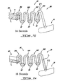
- FIG. 1 illustrates standard siphon valves connecting a first and a second chamber versus the serial siphon valve system in accordance with an illustrative embodiment of the present invention
- FIG. 2 is a perspective view of the fluidic device in accordance with an illustrative embodiment of the present invention
- FIG. 3 is an enlarged view of portion 3 of FIG. 2 ;
- FIG. 4 is a schematic view of a fluidic network in accordance with an illustrative embodiment of the present invention.
- FIG. 5 is an exploded view of the fluidic device of FIG. 2 ;
- FIG. 6 is an exploded sectional schematic representation of a fluidic device in accordance with an illustrative embodiment of the present invention.
- FIGS. 7A to 7J are sequential views of the present serial siphon valve system in action in accordance with an illustrative embodiment of the present invention.
- FIG. 8 illustrates the spin profile used to control the flow of liquid in the serial siphon valve system of FIGS. 7A to 7J .
- the present invention provides serial micro-valves actuated by capillary and centripetal forces for controlling the displacement of liquid into micro-channels from a chamber to another.
- the present invention also provides robust passive valves enabling complex integrations into a centripetal fluidic platform.
- this platform can be used for micro-total analysis systems ( ⁇ TAS) dedicated for bioassays, chemical assays, and diagnostic assays.
- ⁇ TAS micro-total analysis systems
- the present invention provides a method to control minute volume of liquids centripetally-motivated into micro-channels. More precisely, the invention allows the sequential delivery of liquids from one reservoir/chamber to another chamber/reservoir using siphon valves. More particularly, this invention provides serial siphon valves enabling to apply successive centripetal accelerations and decelerations applied to a rotary platform in order to sequentially distribute liquids without the risk of unwanted valve bursting.
- the serial siphon structures are composed of siphon valves separated from each other by a capillary valve (or stopper).
- a capillary valve or stopper.
- the liquid from the upstream chamber is blocked into the first siphon valve as soon as the liquid level in the siphon canal reaches the level of the liquid in the upstream chamber.
- the centripetal acceleration is decreased below the capillary force intensity, the liquid in the siphon canal is moved by the capillary force until it reaches the first capillary valve (stopper) where the liquid stops.
- the first stopper bursts but, because of high centripetal acceleration, the second siphon does not prime. Priming of the second siphon occurs only when the centripetal acceleration is reduced again. Priming of any subsequent siphon occurs based on the same principle.
- a co-radial arrangement of siphon structures, each separated by a capillary valve obviates the need for a chamber between each siphon valve (designated “standard siphon valve” herein), thereby saving radial space.
- the present invention provides an arrangement of siphons (or siphon valves) and capillary valves for the rotational-cycle dependent release of liquid within a centripetal fluidic platform in a way that minimizes the use of radial surface area. This is achieved by the use of centripetal force and capillarity of fluidic channels.
- a benefit that this arrangement has over standard siphons with in-between chambers is that it is more compact and it saves area in the radial dimension during cycles of rotating and stopping (see FIG. 1 ).
- this arrangement of siphons and capillary valves better preserves the potential energy of liquids during cycles of rotating and stopping than the standard siphon design. This ability is important when liquid reagents need to be released from upstream locations at specific times for use downstream on a centripetal fluidic device.
- the present invention describes a system to control the release of fluid from an upstream chamber to a downstream chamber on a rotor by the use of co-radial siphon structures and capillary valves that enable to control the movement of liquids in a fluidic system by the use of alternating cycles of rotating and stopping (as illustrated in and as will be described with reference to FIGS. 7A-7J and 8 ). More specifically, FIG. 1 illustrates standard siphon valves connecting an upstream outlet or dispensing chamber to a downstream inlet or receiving chamber versus a serial siphon design in accordance with a non-limiting embodiment of the present invention. Initially, chambers C 1 are filled in for both systems at radius R 1 .
- a spin-stop-spin cycle allows the liquid to travel from C 1 to C 2 at radius R 2 , and then to C 3 at radius R 3 .
- the same spin-stop-spin cycle allows the liquid to move only from C 1 to C 2 at radius R 2 .
- the general principle of operation is generally based upon the principles of capillary wicking and valving.
- the surface energy of the walls of the siphon was increased by exposure to oxygen plasma. This enables the spontaneous wicking of an aqueous solution into the siphon.
- the capillary valves are structures at which the approaching front of the liquid experiences a dramatic increase of contact angle, such that the liquid movement is stopped.
- a G-force higher than the capillary force is produced in the siphon canal, the liquid is displaced into the siphon canal toward the center of the rotor until the pressure of the liquid column within the siphon canal is equal to the pressure of the liquid in the upstream chamber.
- the liquid primes the siphon and reaches the first capillary valve (the aforementioned stopper or blocker). At a low spinning rate, this valve constrains the liquid and avoids any unwanted priming of the second siphon. A subsequent high spin will burst the first capillary valve and force the liquid to reach pressure equilibrium into the canal of the second siphon. Cycles of spin and stop will therefore prime sequentially the different siphon valves of the serial siphon system.
- the first capillary valve the aforementioned stopper or blocker
- FIG. 2 shows a fluidic device 10 in accordance with an illustrative embodiment of the present invention.
- the fluidic device is a microfluidic centripetal device.
- the microfluidic centripetal device 10 is a microfluidic centripetal platform comprising a rotor in the form of a rotating disk 12 .
- the rotating disk 12 includes a central hole 14 for receiving a rotary actuator (not shown) as is known in the art, which can spin the rotary disk 12 in the direction shown by arrow 16 .
- the rotating disk 12 includes a main body or platform 18 , including a fluidic network in the form of a microfluidic network 20 (for this non-limiting example).
- there are two microfluidic networks 20 of course, a greater or lesser number can be contemplated within the scope of the present invention.
- a greater or lesser number of siphon structures can be contemplated within the scope of the present invention.
- the microfluidic network 20 includes an upstream dispensing chamber 22 , a radially outwardly downstream receiving chamber 24 and a serial siphon valve conduit 26 therebetween.
- the dispensing and receiving chambers 22 and 24 are longitudinal curved structures formed in the body 18 of the disk 12 near the circumference 28 thereof.
- the serial siphon valve conduit 26 comprises series of contiguous siphon valve structures 30 A, 30 B, 30 C and 30 D which are in fact portions of the conduit 26 .
- the siphon valves 30 A 30 B, 30 C and 300 are inverted U-shaped tunnels or canals and generally co-radial.
- Each siphon valve 30 A, 30 B, 30 C and 30 D includes respective first and second branches in the form of a respective inlet siphon canal ( 32 A, 32 B, 32 C, 320 ) and a respective outlet siphon canal ( 34 A, 34 B, 34 C and 34 D) respectively.
- Each siphon valve 30 A, 30 B, 30 C and 30 D includes a respective bend (i.e. the top of the inverted U-shape) 36 A, 36 B, 36 C and 36 D formed between its adjacent inlet and outlet siphon canals ( 32 A, 32 B, 32 C, 32 D) and ( 34 A, 34 B, 34 C and 34 D) respectively.
- the siphon valves 30 A, 30 B, and 30 C are each contiguous the next adjacent siphon valve, namely 30 B, 30 C and 30 D respectively by way of a respective bend 38 , 40 and 42 . More specifically, bend 38 is formed between canals 34 A and 32 B, bend 40 is formed between canals 34 B and 32 C and bend 42 is formed between canals 34 C and 32 D.
- the serial siphon valve conduit 26 includes an inlet aperture 44 formed at the free end of the siphon canal 32 A and positioned within the dispensing chamber 22 near its outwardly radial wall 46 (as opposed to its inwardly radial wall 48 ).
- An outlet aperture 50 is formed at the opposite end of the serial siphon valve conduit 26 and is in fluid communication with the receiving chamber 24 . Specifically in this example, the outlet aperture 50 is positioned near the inwardly radial wall 52 of the chamber 24 (as opposed to the outwardly radial wall 54 ).
- the serial siphon valve conduit 26 has a sinuous or serpentine configuration between the inlet and outlet apertures 44 and 50 , respectively, thereby defining inwardly radial bends 36 A, 36 B, 36 C and 36 D and outwardly radial bends 38 , 40 and 42 .
- the inwardly radial bends 36 A, 36 B, 36 C and 36 D are positioned generally along the same inner arc A 1 (see FIG. 2 ) and the outwardly radial bends 38 , 40 and 42 are positioned generally along the same outer arc A 2 (see FIG. 2 ).
- the serial siphon valve conduit 26 also includes valve structures 56 , 58 and 60 which are capillary valves and which are respectively positioned at and contiguous with bends 38 , 40 and 42 .
- these capillary valves 56 , 58 and 60 which are in the form of discs, enlarge the spatial structure of the bends 38 , 40 and 42 respectively.
- the serial siphon valves 30 A, 30 B, 30 C and 30 D are separated by capillary valves 56 , 58 and 60 .
- each capillary valve 56 , 58 and 60 is connected directly at the bottom of each U-shaped configuration joining adjacent valves, namely at bends 38 , 40 and 42 .
- the capillary valve can be connected to the lateral branches (the inlet or outlet canals) of the siphon valve.
- siphon valves 30 A, 30 B, 30 C and 30 D have a dual siphoning and valve function within the context of the invention as described herein.
- branched inlet and outlet canals as well as the bend interposed therebetween of each siphon valve 30 A, 30 B, 30 C and 30 D forms a respective siphon structure that is contiguous with a valve structure (such as a capillary valve).
- a series of siphon valves includes at least two siphon valves.
- the second siphon valve need not include a valve structure and as such this second siphon valve may be a siphon structure only.
- this second siphon valve may be a siphon structure only.
- siphon valve 30 D which does not include a valve structure since it directly empties into the downstream chamber 24 .
- the siphon valves of the invention can include a siphon structure that is preceded by a valve yet not followed by a valve (such as siphon valve 30 D in the Figures), the term “siphon valve” is also used.
- siphon valve also refers to standard siphons (siphon structures) without the additional valves added by the present invention.
- the serial siphon valve conduit 26 is 1 mm wide and 0.1 mm deep; the upstream dispensing and downstream receiving chambers 22 and 24 , respectively, are 0.6 mm deep; the capillary valves 56 , 58 and 60 , are 2 mm in diameter and 0.3 mm deep; and the whole disk 12 is 120 mm in diameter.
- the serial siphon valve conduit 26 includes four siphon valve, 30 A, 30 B, 30 C and 30 D; the first inlet canal 32 A is configured to draw fluid towards the inwardly radial bend 36 A; and the last outlet canal 34 D is generally longer than the other canals 32 A, 34 A, 32 B, 34 B, 32 C, 34 C and 32 D so as to extend to the downstream chamber 24 .
- the serial siphon valve conduit 26 includes four siphon valve, 30 A, 30 B, 30 C and 30 D; the first inlet canal 32 A is configured to draw fluid towards the inwardly radial bend 36 A; and the last outlet canal 34 D is generally longer than the other canals 32 A, 34 A, 32 B, 34 B, 32 C, 34 C and 32 D so as to extend to the downstream chamber 24 .
- other configurations can also be contemplated within the scope of the present invention.
- FIG. 4 shows another configuration of a microfluidic network 200 in accordance with an illustrative embodiment of the present invention.
- the microfluidic network 200 includes an upstream dispensing chamber 222 , and a downstream receiving chamber 224 as well as a serial siphon valve conduit 226 therebetween.
- the serial siphon valve conduit 226 includes siphon structures or siphon valves 230 A, 230 n and 230 D.
- the siphon valve 230 n shown in dotted line represents the fact that a greater or lesser number of siphon valves can be included between the first and last siphon valves 230 A or 230 D respectively.
- the siphon valve 230 A includes an inlet canal 232 A having an inlet aperture 244 in fluid communication with the chamber 222 and being positioned at the outwardly radial wall 246 thereof.
- This canal 232 A (as opposed to canal 32 A) is configured to draw fluid in the outwardly radial direction relative to the camber 222 towards a first inwardly radial bend 300 which does not include a capillary valve such as valves 301 and 302 at bends 303 and 304 respectively.
- centripetal fluidic devices of the present invention can include a platform and as such the device is the platform or a plurality of like platforms, these devices may also include a platform and an actuator (not illustrated but known in the art) or a plurality of such platforms and an actuator or alternatively a plurality of such platforms with a plurality of actuators.
- the platform or rotary disk 12 will be described In greater detail.
- the rotary disk 12 is in fact a stratified disk assembly.
- Rotary disk assembly 12 therefore assembles three machined disk members, namely a first disk member 70 , a second disk member 72 and a third disk member 74 as well as a pair of adhesive members, namely a first adhesive member 76 and a second adhesive member 78 .
- the disk member 70 serves as the cover and has drilled holes 80 for the purpose of input of liquid and output of air.
- the first adhesive member 76 serves to bond the first and second disks 70 and 72 respectively.
- the first adhesive member 76 includes cut openings 82 which define respective sinuous, serpentine or winding configurations. This sinuous configured opening 82 serves to define the serial siphon valve conduit 26 when the assembly 12 is assembled.
- the second disk member 72 has machined capillary valve openings 84 as which will define the capillary valves 56 , 58 and 60 .
- the second disk member 72 also includes an inlet hole 85 and an outlet hole 86 which when interfaced with the cut opening 82 provide the inlet and outlet apertures 44 and 50 , respectively.
- the first adhesive member 76 and the second disk member 72 also include respective holes 87 and 88 , which correspond to holes 80 , for enabling the flow of liquid between different layers.
- the second adhesive member 78 bonds the second and third disk members 72 and 74 respectively and includes arch-shaped upstream and downstream formations 90 and 92 , respectively, that are complementary to the upstream and downstream chamber grooves 94 and 96 , respectively, that are machined into the third disk 74 for defining the upstream and downstream chambers 22 and 24 , respectively.
- the formations 90 and 92 are openings and the chambers 22 and 24 are formed between grooves 94 and 96 and the second disk 72 .
- the serial siphon conduit 26 and the capillary valves 56 , 58 and 60 are formed between the disks 70 and 72 (with the second adhesive member 78 intervening or being otherwise open).
- the disk members 70 , 72 and 74 and the adhesive members 76 and 78 include respective and complementary central holes 98 , 100 , 102 , 104 and 106 that together form the central disk hole 14 .
- the first and second disks 70 and 72 are exposed to oxygen plasma for the purpose of increasing their surface energies and enabling the spontaneous wicking of aqueous solutions into the serial siphon valve conduit 26 .
- first and second disk members 70 and 72 are each 0.6 mm thick, whereas the third disk member 74 is 1.2 mm thick and the first and second adhesive members 76 and 78 are each 0.1 mm thick,
- the disk 12 can be manufactured by several technologies including but not limited to: micromachining, hot embossing, injection molding, photolithography chemical etching, laser welding, ultra-sound bounding, thermal bounding, and chemical bounding.
- the disk 12 which serves as the microfluidic platform can be provided in other suitable configurations or constructions within the scope of the present invention.
- a variety of disk members having various machined constructions, cuts or openings can be interfaced to create the microfluidic networks of the present invention.
- FIG. 6 is a schematic cross sectional (not to scale) representation of a disassembled disk assembly 112 comprising first, second and third members 114 , 116 and 118 respectively.
- the first disk member 114 has a machined underface 120 defining grooves 122 that will provide the serial siphon valve conduit when assembled with the second and third disk members 116 and 118 .
- the second disk member 116 includes openings 124 through its body that define the capillary valves between the first and third disk member 114 and 118 .
- the second disk member 116 may also include other openings 125 to provide inlets or outlets example.
- the third disk member 118 includes machined grooves 126 in its top face 128 that define the upstream and downstream chambers when assembled to the first and second disk members 114 and 116 .
- These disk members 114 , 116 and 118 can be adhered together by various ways known in the art within the context of the present invention. It is understood that the components of FIG. 6 are shown in dotted line as to represent an embodiment rather than show proper alignment.
- the present invention may be used for any application that specifically requires the sequential flow of different liquids through a channel. For example, if a DNA microarray is immobilized in a channel or chamber, one may want to perform a hybridization step in which enzyme-labeled complementary DNA is made to flow through the channel in cycle 1 . In cycle 2 , one may want to wash with a buffer solution. Finally, a substrate solution specific for the enzyme used may follow in cycle 3 .
- Another application might be the purification of DNA. One may use glass beads (for capturing DNA) in a channel. The sequential flow of a sample containing DNA with impurities, one or more wash buffer volumes, and an elution buffer could be conducted.
- FIGS. 7A to 7J illustrate the present invention in action.
- a non-limiting example of a corresponding spin profile is also shown in FIG. 8 .
- FIG. 8 illustrates the spin profile used to control the release of liquid L from an upstream chamber 22 into a downstream chamber 24 by the use of serial siphon microfluidic structures such as the serial siphon valve conduit 26 .
- Rotation at 1,500 RPM generates centrifugal acceleration that enables the liquid front to travel beyond the capillary valves. After about 24 seconds (see FIGS. 7J and 8 ), most of the liquid L from the upstream chamber 22 can be transferred to the downstream chamber 24 . In this example a total of five cycles of rotation and stopping are demonstrated. The number of cycles that may be incorporated into this system would be limited by the liquid front's (F 1 , F 2 , F 3 , F 4 , F 5 , F 6 , F 7 , F 8 , F 9 , F 10 ) ability to “pull” the increasing amount of liquid L behind it.
- FIG. 7A shows the liquid front F 1 at 2 seconds
- FIG. 7B shows the liquid front F 2 at 5 seconds
- FIG. 7C shows the liquid front F 3 at 6 seconds
- FIG. 7D shows the liquid front F 4 at 8 seconds
- FIG. 7E shows the liquid front F 5 at 10 seconds
- FIG. 7F shows the liquid front F 6 at 12 seconds
- FIG. 7G shows the liquid front F 7 at 14 seconds
- FIG. 7H shows the liquid front F 8 at 16 seconds
- FIG. 7I shows the liquid front F 9 at 18 seconds
- FIG. 7J shows the liquid front F 10 at 24 seconds.
- the design of the disk was accomplished by the use of SolidWorks 2005 computer aided design software from Solidworks Corporation (Concord, Mass.).
- a rotating disk for the demonstration of the serial siphon concept was constructed by the use of standard compact disks (CD 1.1 mm thick) and digital versatile disks (DVD, 0.6 mm thick) purchased from U-Tech Media Corporation (Taiwan).
- the disks were machined by the use of a QuickCircuit 5000 computer numerical control system from T-Tech, Inc. (Norcross, Ga.).
- a 100 micrometer thick transfer adhesive called Flexrnount DEM 200 Clear, V-95 150 Poly H-9 V-95-4, from Flexcon, Inc. (Spencer, Mass.) was used to bond the disks together.
- the digital video recording system was composed of a camera model A301bc made by Basler (Germany) with a resolution of 640 ⁇ 480 pixels; able to capture a maximum of 80 frames per second.
- a Computer (Japan) brand 10 ⁇ zoom lens was mounted on the camera and focused on the surface for the rotating disk.
- a strobe light model MVS-4200 from PerkinElmer (Fremont, Calif.) was set to 6 ⁇ s duration and used to help capture a clear image of the disk while rotating.
- a retro-reflective fiber optic sensor model D10 made by Banner (Minneapolis, Minn.) was deployed right above the edge of the rotating disk.
- a white square mark (2 mm ⁇ 2 mm) was placed on the edge of the disk and aligned such that it fell immediately below the light spot emitted from the fiber optic sensor when the microfluidic structures of interest on the rotating disk came into view of the camera.
- a pulse was sent to the video capture board which then immediately triggered the camera and strobe light to acquire one image frame per revolution.
- the disk 12 is a stratified assembly of three machined polycarbonate disks and two cut adhesives as previously described with reference to FIG. 5 .
- the different components of the disk 12 were aligned and pressed together to form an assembly. All the fluidic surfaces of the disk 12 were hydrophilic.
- the upstream chamber 22 was filled with water colored with red food coloring.
- the spin profile depicted in FIG. 8 was applied to the filled disk 12 .
- the serial siphon valves 30 A, 30 B, 30 C, 30 D are separated by capillary valves (or “stoppers”) 56 , 58 and 60 . It was observed that the liquid L in the upstream chamber 22 traveled along the serial siphon valve conduit 26 as seen in the sequence of the drawings of FIGS. 7A-7J .
- the liquid L from the upstream (dispensing) chamber 22 is blocked into the first siphon valve 30 A (in canal 32 A at the precipice of bend 36 A) as soon as the liquid level in the siphon canal reaches the level T of the liquid L in the upstream chamber 22 at liquid front F 1 (see FIGS. 7A and 8 at 2 seconds).
- the liquid L therein is moved by the capillary force past bend 36 A and through outlet canal 34 A until it reaches the first capillary valve 56 where the liquid stops L
- the liquid front F 2 is at the precipice of bend 38 which includes the valve 56 .
- the first stopper or valve 56 bursts i.e. is traversed by the liquid L but, because of high centripetal acceleration, the second siphon valve 30 B does not prime (see FIGS. 7C and 8 at 6 seconds).
- the liquid front F 3 stops within inlet canal 32 B (at the precipice of bend 36 B) when it is at the level T of the liquid L in the chamber 22 .
- Priming of the second siphon valve 32 B occurs only when the centripetal acceleration is reduced again.
- the liquid L flows via bend 36 B into canal 34 B and stops (F 4 ) at the second capillary valve 58 .
- Priming of any subsequent siphon valve ( 30 C and 30 D in this case) occurs based on the same principle as illustrated in the steps shown in FIGS. 7E , 7 F, 7 G, 7 H, 7 I, 7 J and FIG. 8 from 9 to 24 seconds.
- the spin sequence illustrated in FIGS. 7I , 7 J and 8 from 17 to 24 seconds is made longer simply to allow aspiration of all the liquid L in the serial siphon valve conduit 26 to fill the downstream receiving chamber 24 .
- centrifugation times presented above for the different cycles is not critical and may be modified without altering the general concept detailed herein.
Abstract
Description
Claims (11)
Priority Applications (1)
| Application Number | Priority Date | Filing Date | Title |
|---|---|---|---|
| US12/529,199 US8534319B2 (en) | 2007-03-02 | 2008-03-03 | Serial siphon valves for fluidic or microfluidic devices |
Applications Claiming Priority (3)
| Application Number | Priority Date | Filing Date | Title |
|---|---|---|---|
| US90437207P | 2007-03-02 | 2007-03-02 | |
| PCT/CA2008/000420 WO2008106782A1 (en) | 2007-03-02 | 2008-03-03 | Serial siphon valves for fluidic or microfluidic devices |
| US12/529,199 US8534319B2 (en) | 2007-03-02 | 2008-03-03 | Serial siphon valves for fluidic or microfluidic devices |
Publications (2)
| Publication Number | Publication Date |
|---|---|
| US20110094600A1 US20110094600A1 (en) | 2011-04-28 |
| US8534319B2 true US8534319B2 (en) | 2013-09-17 |
Family
ID=39737736
Family Applications (1)
| Application Number | Title | Priority Date | Filing Date |
|---|---|---|---|
| US12/529,199 Active 2030-03-28 US8534319B2 (en) | 2007-03-02 | 2008-03-03 | Serial siphon valves for fluidic or microfluidic devices |
Country Status (5)
| Country | Link |
|---|---|
| US (1) | US8534319B2 (en) |
| EP (1) | EP2135069A4 (en) |
| CN (1) | CN101715553A (en) |
| CA (1) | CA2679395C (en) |
| WO (1) | WO2008106782A1 (en) |
Cited By (2)
| Publication number | Priority date | Publication date | Assignee | Title |
|---|---|---|---|---|
| US20140360605A1 (en) * | 2011-11-11 | 2014-12-11 | Shimadzu Corporation | Passage-switching valve |
| US20160167045A1 (en) * | 2014-12-10 | 2016-06-16 | The Regents Of The University Of California | Centrifugal microfluidic platform for automated media exchange |
Families Citing this family (27)
| Publication number | Priority date | Publication date | Assignee | Title |
|---|---|---|---|---|
| GB2464721C (en) | 2008-10-23 | 2013-08-14 | Biosurfit Sa | Jet deflection device |
| GB2466644B (en) * | 2008-12-30 | 2011-05-11 | Biosurfit Sa | Liquid handling |
| KR20110056168A (en) * | 2009-11-20 | 2011-05-26 | 삼성전자주식회사 | Microfluidic device, light irradiation apparatus, microfluidic system comprising the same and method for driving the system |
| GB2476474B (en) | 2009-12-22 | 2012-03-28 | Biosurfit Sa | Surface plasmon resonance detection system |
| GB2479139A (en) * | 2010-03-29 | 2011-10-05 | Biosurfit Sa | A liquid distribution and metering device |
| KR101956265B1 (en) | 2011-03-24 | 2019-06-24 | 바이오서핏 에스.에이. | Control of liquid flow sequence on microfluidic device |
| US9186672B2 (en) | 2011-04-18 | 2015-11-17 | The Regents Of The Univeristy Of California | Microfluidic device for whole blood sample preparation |
| GB2491813A (en) * | 2011-06-03 | 2012-12-19 | Univ Dublin City | A microfluidic device with sacrificial valve |
| JP6257521B2 (en) | 2011-12-08 | 2018-01-10 | バイオサーフィット、 ソシエダッド アノニマ | Determination of sequential dispensing and sedimentation rate indicators |
| KR20140008976A (en) * | 2012-07-11 | 2014-01-22 | 삼성전자주식회사 | Microfluidic structure, microfluidic device having the same and method controlling the microfluidic device |
| US20140017806A1 (en) * | 2012-07-11 | 2014-01-16 | Samsung Electronics Co., Ltd. | Microfluidic structure, microfluidic device having the same and method of controlling the microfluidic device |
| US8734734B2 (en) | 2012-09-12 | 2014-05-27 | LaMotte Chemical Products Company | Liquid analysis cartridge |
| EP2928607B1 (en) | 2012-12-05 | 2019-08-07 | Radisens Diagnostics Ltd. | Valving system for use in centrifugal microfluidic platforms |
| US10888862B2 (en) | 2012-12-05 | 2021-01-12 | Radisens Diagnostics Limited | Acceleration-primed valving system for centrifugal microfluidics |
| GB2515116A (en) * | 2013-06-14 | 2014-12-17 | Univ Dublin City | Microfluidic Device |
| US10493416B2 (en) * | 2014-05-08 | 2019-12-03 | Osaka University | Thermal convection generating chip and liquid measuring device |
| US9885352B2 (en) | 2014-11-25 | 2018-02-06 | Genia Technologies, Inc. | Selectable valve of a delivery system |
| EP3173149A1 (en) * | 2015-11-26 | 2017-05-31 | Roche Diagnostics GmbH | Determining a quantity of an analyte in a blood sample |
| JP7387430B2 (en) * | 2016-06-27 | 2023-11-28 | ゾエティス サービシズ リミテッド ライアビリティ カンパニー | Devices with modified conduits |
| CN108732339B (en) | 2017-04-19 | 2021-04-13 | 光宝电子(广州)有限公司 | Flow channel device for multiple reaction biological detection and detection method thereof |
| TWI655417B (en) * | 2017-05-05 | 2019-04-01 | Feng Chia University | Microfluidic testing device and microfluidic control method thereof |
| JP2019220682A (en) | 2018-06-15 | 2019-12-26 | シャープ株式会社 | Method of manufacturing solid-state imaging element |
| CN111205966B (en) | 2020-04-18 | 2020-07-21 | 博奥生物集团有限公司 | Sample extraction chip and biological reaction device |
| CN112481123B (en) * | 2020-11-16 | 2022-02-15 | 大连理工大学 | Microfluidic system and method for researching shear force and biochemical factor gradient regulation and control of cell scratch repair |
| CN112808336A (en) * | 2021-02-09 | 2021-05-18 | 深圳市亚辉龙生物科技股份有限公司 | Micro-fluidic chip |
| WO2023064815A1 (en) * | 2021-10-12 | 2023-04-20 | University Of Virginia | A microfluidic strucure for differential extraction |
| CN115074230B (en) * | 2022-07-21 | 2023-05-23 | 北京泰豪生物科技有限公司 | Reagent controlled release module, bioreactor and biological detection device |
Citations (16)
| Publication number | Priority date | Publication date | Assignee | Title |
|---|---|---|---|---|
| US5409665A (en) | 1993-09-01 | 1995-04-25 | Abaxis, Inc. | Simultaneous cuvette filling with means to isolate cuvettes |
| US5693223A (en) | 1993-11-26 | 1997-12-02 | Ngk Insulators, Ltd. | Column and column device for low pressure-high speed liquid chromatography and a method for using said column device |
| US5693233A (en) * | 1992-04-02 | 1997-12-02 | Abaxis | Methods of transporting fluids within an analytical rotor |
| US6143248A (en) | 1996-08-12 | 2000-11-07 | Gamera Bioscience Corp. | Capillary microvalve |
| WO2002043866A2 (en) | 2000-12-01 | 2002-06-06 | Burstein Technologies, Inc. | Apparatus and methods for separating components of particulate suspension |
| US20020106786A1 (en) * | 2000-05-15 | 2002-08-08 | Carvalho Bruce L. | Microfluidics devices and methods for performing cell based assays |
| US20030044322A1 (en) | 2001-08-28 | 2003-03-06 | Gyros Ab | Retaining microfluidic microcavity and other microfluidic structures |
| US6620478B1 (en) * | 1993-06-15 | 2003-09-16 | Gyros Ab | Circular disk containing microchannel/microcavity structures |
| US20040096867A1 (en) * | 2001-03-19 | 2004-05-20 | Per Andersson | Characterization of reaction variables |
| US6752961B2 (en) | 1993-09-01 | 2004-06-22 | Abaxis, Inc. | Modified siphons for improving metering precision |
| US20040120856A1 (en) * | 2001-03-19 | 2004-06-24 | Per Andersson | Structural units that define fluidic functions |
| US20050129583A1 (en) * | 2003-12-12 | 2005-06-16 | 3M Innovative Properties Company | Sample mixing on a microfluidic device |
| US20050202471A1 (en) | 1999-12-23 | 2005-09-15 | Gyros Ab | Integrated microfluidic disc |
| US20050277195A1 (en) * | 2002-04-30 | 2005-12-15 | Gyros Ab | Integrated microfluidic device (ea) |
| WO2006093978A2 (en) | 2005-03-02 | 2006-09-08 | The Regents Of The University Of California | Flow switching on a multi-structured microfluidic cd (compact disc) using coriolis force |
| DE102005048233A1 (en) | 2005-10-07 | 2007-04-12 | Albert-Ludwigs-Universität Freiburg | Apparatus and method for handling a liquid sample using a siphon structure |
-
2008
- 2008-03-03 WO PCT/CA2008/000420 patent/WO2008106782A1/en active Application Filing
- 2008-03-03 CN CN200880012605A patent/CN101715553A/en active Pending
- 2008-03-03 CA CA2679395A patent/CA2679395C/en active Active
- 2008-03-03 US US12/529,199 patent/US8534319B2/en active Active
- 2008-03-03 EP EP08714739A patent/EP2135069A4/en not_active Withdrawn
Patent Citations (18)
| Publication number | Priority date | Publication date | Assignee | Title |
|---|---|---|---|---|
| US5693233A (en) * | 1992-04-02 | 1997-12-02 | Abaxis | Methods of transporting fluids within an analytical rotor |
| US6620478B1 (en) * | 1993-06-15 | 2003-09-16 | Gyros Ab | Circular disk containing microchannel/microcavity structures |
| US5518930A (en) * | 1993-09-01 | 1996-05-21 | Abaxis, Inc. | Simultaneous cuvette filling with means to isolate cuvettes |
| US5409665A (en) | 1993-09-01 | 1995-04-25 | Abaxis, Inc. | Simultaneous cuvette filling with means to isolate cuvettes |
| US6752961B2 (en) | 1993-09-01 | 2004-06-22 | Abaxis, Inc. | Modified siphons for improving metering precision |
| US5693223A (en) | 1993-11-26 | 1997-12-02 | Ngk Insulators, Ltd. | Column and column device for low pressure-high speed liquid chromatography and a method for using said column device |
| US6143248A (en) | 1996-08-12 | 2000-11-07 | Gamera Bioscience Corp. | Capillary microvalve |
| US20050202471A1 (en) | 1999-12-23 | 2005-09-15 | Gyros Ab | Integrated microfluidic disc |
| US20020106786A1 (en) * | 2000-05-15 | 2002-08-08 | Carvalho Bruce L. | Microfluidics devices and methods for performing cell based assays |
| WO2002043866A2 (en) | 2000-12-01 | 2002-06-06 | Burstein Technologies, Inc. | Apparatus and methods for separating components of particulate suspension |
| US20040096867A1 (en) * | 2001-03-19 | 2004-05-20 | Per Andersson | Characterization of reaction variables |
| US20040120856A1 (en) * | 2001-03-19 | 2004-06-24 | Per Andersson | Structural units that define fluidic functions |
| US20030044322A1 (en) | 2001-08-28 | 2003-03-06 | Gyros Ab | Retaining microfluidic microcavity and other microfluidic structures |
| US20050153431A1 (en) * | 2001-08-28 | 2005-07-14 | Gyros Ab | Retaining microfluidic microcavity and other microfluidic structures |
| US20050277195A1 (en) * | 2002-04-30 | 2005-12-15 | Gyros Ab | Integrated microfluidic device (ea) |
| US20050129583A1 (en) * | 2003-12-12 | 2005-06-16 | 3M Innovative Properties Company | Sample mixing on a microfluidic device |
| WO2006093978A2 (en) | 2005-03-02 | 2006-09-08 | The Regents Of The University Of California | Flow switching on a multi-structured microfluidic cd (compact disc) using coriolis force |
| DE102005048233A1 (en) | 2005-10-07 | 2007-04-12 | Albert-Ludwigs-Universität Freiburg | Apparatus and method for handling a liquid sample using a siphon structure |
Non-Patent Citations (1)
| Title |
|---|
| Stefan Haeberle, et al; "Microfluidic platforms for lab-on-a-chip applications", Lab Chip, 2007: DOI: 10.1039/b706364b, vol. 7, pp. 1094-1110 (see section III Centrifugal microfluidics), Received Apr. 26, 2007, Accepted Jun. 25, 2007. |
Cited By (4)
| Publication number | Priority date | Publication date | Assignee | Title |
|---|---|---|---|---|
| US20140360605A1 (en) * | 2011-11-11 | 2014-12-11 | Shimadzu Corporation | Passage-switching valve |
| US9200715B2 (en) * | 2011-11-11 | 2015-12-01 | Shimadzu Corporation | Passage-switching valve |
| US20160167045A1 (en) * | 2014-12-10 | 2016-06-16 | The Regents Of The University Of California | Centrifugal microfluidic platform for automated media exchange |
| US10166541B2 (en) * | 2014-12-10 | 2019-01-01 | The Regents Of The University Of California | Centrifugal microfluidic platform for automated media exchange |
Also Published As
| Publication number | Publication date |
|---|---|
| EP2135069A1 (en) | 2009-12-23 |
| EP2135069A4 (en) | 2011-03-09 |
| CA2679395A1 (en) | 2008-09-12 |
| WO2008106782A1 (en) | 2008-09-12 |
| US20110094600A1 (en) | 2011-04-28 |
| CN101715553A (en) | 2010-05-26 |
| CA2679395C (en) | 2016-08-30 |
Similar Documents
| Publication | Publication Date | Title |
|---|---|---|
| US8534319B2 (en) | Serial siphon valves for fluidic or microfluidic devices | |
| EP1284818B1 (en) | Bidirectional flow centrifugal microfluidic devices | |
| Clime et al. | Active pumping and control of flows in centrifugal microfluidics | |
| Gorkin III et al. | Centrifugo-pneumatic valving utilizing dissolvable films | |
| US7300199B2 (en) | Retaining microfluidic microcavity and other microfluidic structures | |
| US20090266421A1 (en) | Flow control in microfluidic systems | |
| JP4368804B2 (en) | Parallel processing of microfluidic devices | |
| US20070113908A1 (en) | Valve for microfluidic chips | |
| EP2283924B1 (en) | Inlet unit with means supporting liquid entrance into a microchannel structure | |
| KR102039515B1 (en) | Microfluidic device | |
| US7914753B2 (en) | Analytical system, and analytical method and flow structure thereof | |
| JP2017521639A (en) | Rotatable cartridge for analyzing biological samples | |
| US6743632B2 (en) | Directional acceleration vector-driven displacement of fluids (DAVD-DOF) | |
| US11344888B2 (en) | Fluidic device for aliquoting and combinatorial mixing of liquids | |
| WO2018033609A1 (en) | A microfluidic device | |
| Henderson et al. | The centrifugal microfluidic: Lab-on-a-disc platform | |
| JP2016218071A (en) | Fluid handling device, fluid handling method, and fluid handling system | |
| Kinahan et al. | Nucleic acid purification on a Lab-on-a-Disc with time-controlled incubation | |
| Zoval et al. | Centrifuge based fluidic platforms | |
| Schwemmer | Advanced centrifugal microfluidics: timing, aliquoting and volume reduction | |
| CA2456421A1 (en) | Retaining microfluidic microcavity and other microfluidic structures |
Legal Events
| Date | Code | Title | Description |
|---|---|---|---|
| AS | Assignment |
Owner name: INFECTIO RECHERCHE INC., CANADA Free format text: ASSIGNMENT OF ASSIGNORS INTEREST;ASSIGNORS:BERGERON, MICHEL G.;PEYTAVI, REGIS;KIDO, HORACIO;SIGNING DATES FROM 20070522 TO 20070601;REEL/FRAME:024026/0395 Owner name: THE REGENTS OF THE UNIVERSITY OF CALIFORNIA, CALIF Free format text: ASSIGNMENT OF ASSIGNORS INTEREST;ASSIGNOR:MADOU, MARC;REEL/FRAME:024026/0465 Effective date: 20100210 Owner name: UNIVERSITE LAVAL, CANADA Free format text: ASSIGNMENT OF ASSIGNORS INTEREST;ASSIGNOR:INFECTIO RECHERCHE INC.;REEL/FRAME:024026/0435 Effective date: 20071214 Owner name: THE REGENTS OF THE UNIVERSITY OF CALIFORNIA, CALIF Free format text: ASSIGNMENT OF ASSIGNORS INTEREST;ASSIGNOR:INFECTIO RECHERCHE INC.;REEL/FRAME:024026/0435 Effective date: 20071214 |
|
| AS | Assignment |
Owner name: NATIONAL INSTITUTES OF HEALTH (NIH), U.S. DEPT. OF Free format text: CONFIRMATORY LICENSE;ASSIGNOR:UNIVERSITY OF CALIFORNIA;REEL/FRAME:027018/0791 Effective date: 20110519 |
|
| STCF | Information on status: patent grant |
Free format text: PATENTED CASE |
|
| FPAY | Fee payment |
Year of fee payment: 4 |
|
| FEPP | Fee payment procedure |
Free format text: ENTITY STATUS SET TO UNDISCOUNTED (ORIGINAL EVENT CODE: BIG.); ENTITY STATUS OF PATENT OWNER: LARGE ENTITY |
|
| MAFP | Maintenance fee payment |
Free format text: PAYMENT OF MAINTENANCE FEE, 8TH YEAR, LARGE ENTITY (ORIGINAL EVENT CODE: M1552); ENTITY STATUS OF PATENT OWNER: LARGE ENTITY Year of fee payment: 8 |