US8527955B2 - System and method to classify automated code inspection services defect output for defect analysis - Google Patents

System and method to classify automated code inspection services defect output for defect analysis Download PDF

Info

Publication number
US8527955B2
US8527955B2 US12/558,274 US55827409A US8527955B2 US 8527955 B2 US8527955 B2 US 8527955B2 US 55827409 A US55827409 A US 55827409A US 8527955 B2 US8527955 B2 US 8527955B2
Authority
US
United States
Prior art keywords
tool
defect
code inspection
output
error
Prior art date
Legal status (The legal status is an assumption and is not a legal conclusion. Google has not performed a legal analysis and makes no representation as to the accuracy of the status listed.)
Expired - Fee Related, expires
Application number
US12/558,274
Other versions
US20110067006A1 (en
Inventor
Ian E. BAKER
Kathryn A. BASSIN
Steven Kagan
Susan E. SKRABANEK
Current Assignee (The listed assignees may be inaccurate. Google has not performed a legal analysis and makes no representation or warranty as to the accuracy of the list.)
International Business Machines Corp
Original Assignee
International Business Machines Corp
Priority date (The priority date is an assumption and is not a legal conclusion. Google has not performed a legal analysis and makes no representation as to the accuracy of the date listed.)
Filing date
Publication date
Application filed by International Business Machines Corp filed Critical International Business Machines Corp
Priority to US12/558,274 priority Critical patent/US8527955B2/en
Assigned to INTERNATIONAL BUSINESS MACHINES CORPORATION reassignment INTERNATIONAL BUSINESS MACHINES CORPORATION ASSIGNMENT OF ASSIGNORS INTEREST (SEE DOCUMENT FOR DETAILS). Assignors: KAGAN, STEVEN, BAKER, IAN E., BASSIN, KATHRYN A., SKRABANEK, SUSAN E.
Publication of US20110067006A1 publication Critical patent/US20110067006A1/en
Priority to US13/923,581 priority patent/US8924936B2/en
Application granted granted Critical
Publication of US8527955B2 publication Critical patent/US8527955B2/en
Priority to US14/510,296 priority patent/US9176844B2/en
Priority to US14/844,422 priority patent/US9442821B2/en
Priority to US15/215,664 priority patent/US9753838B2/en
Expired - Fee Related legal-status Critical Current
Adjusted expiration legal-status Critical

Links

Images

Classifications

    • GPHYSICS
    • G06COMPUTING; CALCULATING OR COUNTING
    • G06FELECTRIC DIGITAL DATA PROCESSING
    • G06F11/00Error detection; Error correction; Monitoring
    • G06F11/36Preventing errors by testing or debugging software
    • G06F11/3668Software testing
    • GPHYSICS
    • G06COMPUTING; CALCULATING OR COUNTING
    • G06FELECTRIC DIGITAL DATA PROCESSING
    • G06F11/00Error detection; Error correction; Monitoring
    • G06F11/36Preventing errors by testing or debugging software
    • G06F11/3604Software analysis for verifying properties of programs
    • GPHYSICS
    • G06COMPUTING; CALCULATING OR COUNTING
    • G06FELECTRIC DIGITAL DATA PROCESSING
    • G06F9/00Arrangements for program control, e.g. control units
    • G06F9/06Arrangements for program control, e.g. control units using stored programs, i.e. using an internal store of processing equipment to receive or retain programs
    • G06F9/44Arrangements for executing specific programs
    • G06F9/445Program loading or initiating
    • G06F9/44589Program code verification, e.g. Java bytecode verification, proof-carrying code

Definitions

  • the present invention generally relates to defect analysis, and more particularly, to a method and system to classify automated code inspection services defect output for defect analysis.
  • Software testing may involve verifying the correctness, completeness, security, quality, etc. of a product. During testing, a technical investigation may be performed by, for example, executing a program or application with the intent to find errors. If errors are found, one or more areas in the software code may be identified based on the errors. Therefore, developers may alter the code in the identified regions to obviate the error.
  • ODC Orthogonal Defect Classification
  • DAS/DRM defect analysis starter/defect reduction method
  • a project e.g., a software project of an organization
  • code inspection services from the service provider on an as-needed basis without requiring any tool purchase or licensing costs for tools they may only need to leverage on a limited basis.
  • a project may, for example, utilize a plurality of code inspection services (e.g., specifically tailored for their project) and receive code inspection services reports from the service provider.
  • code inspection services e.g., specifically tailored for their project
  • a method is implemented in a computer infrastructure having computer executable code tangibly embodied on a computer readable storage medium having programming instructions.
  • the programming instructions are operable to receive a tool error output determined by a code inspection tool and select at least one defect classification mapping profile based on the code inspection tool. Additionally, the programming instructions are operable to map the tool error output to one or more output classifications using the selected at least one defect classification mapping profile and generate at least one report based on the one or more output classifications.
  • a system comprises an error output receiving tool operable to receive a tool error output determined by a code inspection tool and a selection tool operable to select at least one defect classification mapping profile based on the code inspection tool. Additionally, the system comprises a defect classification mapping tool operable to map the tool error output to one or more output classifications using the selected at least one defect classification mapping profile and a report generation tool operable to generate at least one report based on the one or more output classifications.
  • a computer program product comprising a computer usable storage medium having readable program code embodied in the medium.
  • the computer program product includes at least one component operable to receive a tool error output determined by a code inspection tool and select at least one defect classification mapping profile based on the code inspection tool. Additionally, the at least one component is operable to map the tool error output to one or more output classifications using the selected at least one defect classification mapping profile and generate at least one defect analysis metric based on the one or more output classifications.
  • a computer system for classifying automated code inspection services defect output for defect analysis comprises a CPU, a computer readable memory and a computer readable storage media. Additionally, the system comprises first program instructions to receive a tool error output determined by a code inspection tool and second program instructions to select at least one defect classification mapping profile based on the code inspection tool. Furthermore, the system comprises third program instructions to map the tool error output to one or more output classifications using the selected at least one defect classification mapping profile and fourth program instructions to generate at least one defect analysis metric based on the one or more output classifications. The first, second, third and fourth program instructions are stored on the computer readable storage media for execution by the CPU via the computer readable memory
  • FIG. 1 shows an illustrative environment for implementing the steps in accordance with aspects of the invention
  • FIG. 2 shows an exemplary depiction of a high level flow in accordance with aspects of the invention
  • FIGS. 3-18 illustrate exemplary defect classification mapping profiles for different functional areas of code for a first code inspection service in accordance with aspects of the invention
  • FIG. 19 illustrates an exemplary defect classification mapping profile for a second code inspection service in accordance with aspects of the invention
  • FIG. 20 illustrates an exemplary defect classification mapping profile for a third code inspection service in accordance with aspects of the present invention
  • FIG. 21 illustrates an additional exemplary defect classification mapping profile for a fourth code inspection service in accordance with aspects of the invention.
  • FIGS. 22-41 illustrate exemplary defect classification mapping profiles which list possible tool error outputs for a fifth code inspection service in accordance with aspects of the invention
  • FIG. 42 illustrates an exemplary assessment including a rating of results against expectation for each of technical quality, security, memory and accessibility in accordance with aspects of the present invention
  • FIG. 43 illustrates an exemplary quantification of error types in accordance with aspects of the present invention.
  • FIGS. 44-46 illustrate exemplary histograms in accordance with aspects of the present invention.
  • FIG. 47 illustrates an exemplary illustration of defect artifact types mapped to a process point when those defects are injected in accordance with aspects of the present invention
  • FIGS. 48-58 illustrate additional exemplary histograms in accordance with aspects of the present invention.
  • FIG. 59 illustrates a trigger summary in accordance with aspects of the invention.
  • FIG. 60 shows an exemplary flow for performing aspects of the present invention.
  • the present invention generally relates to defect analysis, and more particularly, to system and method to classify automated code inspection services defect output for defect analysis.
  • the present invention utilizes defect classification field rules (e.g., in accordance with a common schema) for classifying and interpreting defects uncovered via automated code inspection subscription service. More specifically, the present invention establishes automated classification rules to interpret the defects uncovered via various automated code inspection tools (e.g., WebKing®, CAST, Purify PlusTM, AppScan®, and ABAP Code Optimizer, amongst other code inspection tools) so that projects can more effectively plan late phase testing needs and reduce high risk or impact defects that would likely otherwise have escaped into production.
  • automated code inspection tools e.g., WebKing®, CAST, Purify PlusTM, AppScan®, and ABAP Code Optimizer, amongst other code inspection tools
  • Implementing the present invention leveraging multiple code inspection tools in a defect removal/analysis test service at the unit test phase of the life cycle, enables projects to realize significant cost savings because, for example, finding and fixing high value defects at this relatively early phase (i.e., unit test) is far less expensive than attempting to find and fix defects in any of the late phase tests (e.g., after unit test), or especially in production.
  • the present invention also enables projects to measure the impact of finding and/or fixing these defects on later test phases. For example, if the project has already adequately addressed security concerns in the automated code inspection, the organization can reduce or eliminate test cases from the execution plan and move to production earlier without sacrificing quality or increasing risk.
  • projects can select any combination of tools to be applied to their code (e.g., WebKing, CAST, Purify Plus, AppScan, and ABAP Code Optimizer).
  • tools e.g., WebKing, CAST, Purify Plus, AppScan, and ABAP Code Optimizer.
  • the output from the inspection i.e., from the selected tools
  • the defect classification mapping tool applies a set of defect classification rules and, in embodiments, a report generation tool produces, for example, an overall defect analysis report based on the output of the defect classification mapping tool.
  • an organization may allow projects to accurately assess the impact of automated code inspections on critical exposure areas, which can in turn be used to more effectively plan late phase testing and production support needs.
  • the defect analysis report will provide insights that will enable projects to optimize, for example, their go-forward test planning.
  • the present invention may be embodied as a system, method or computer program product. Accordingly, the present invention may take the form of an entirely hardware embodiment, an entirely software embodiment (including firmware, resident software, micro-code, etc.) or an embodiment combining software and hardware aspects that may all generally be referred to herein as a “circuit,” “module” or “system.” Furthermore, the present invention may take the form of a computer program product embodied in any tangible medium of expression having computer-usable program code embodied in the medium.
  • the computer-usable or computer-readable medium may be, for example but not limited to, an electronic, magnetic, optical, electromagnetic, infrared, or semiconductor system, apparatus, device, or propagation medium. More specific examples (a non-exhaustive list) of the computer-readable medium would include the following:
  • the computer-usable or computer-readable medium could even be paper or another suitable medium upon which the program is printed, as the program can be electronically captured, via, for instance, optical scanning of the paper or other medium, then compiled, interpreted, or otherwise processed in a suitable manner, if necessary, and then stored in a computer memory.
  • a computer-usable or computer-readable medium may be any medium that can contain, store, communicate, propagate, or transport the program for use by or in connection with the instruction execution system, apparatus, or device.
  • the computer-usable medium may include a propagated data signal with the computer-usable program code embodied therewith, either in baseband or as part of a carrier wave.
  • the computer usable program code may be transmitted using any appropriate medium, including but not limited to wireless, wireline, optical fiber cable, RF, etc.
  • Computer program code for carrying out operations of the present invention may be written in any combination of one or more programming languages, including an object oriented programming language such as JAVA, Smalltalk, C++ or the like and conventional procedural programming languages, such as the “C” programming language or similar programming languages.
  • the program code may execute entirely on the user's computer, partly on the user's computer, as a stand-alone software package, partly on the user's computer and partly on a remote computer or entirely on the remote computer or server.
  • the remote computer may be connected to the user's computer through any type of network. This may include, for example, a local area network (LAN) or a wide area network (WAN), or the connection may be made to an external computer (for example, through the Internet using an Internet Service Provider).
  • LAN local area network
  • WAN wide area network
  • Internet Service Provider for example, AT&T, MCI, Sprint, EarthLink, MSN, GTE, etc.
  • FIG. 1 shows an illustrative environment 10 for managing the processes in accordance with the invention.
  • the environment 10 includes a server or other computing system 12 that can perform the processes described herein.
  • the server 12 includes a computing device 14 .
  • the computing device 14 can be resident on a network infrastructure or computing device of a third party service provider (any of which is generally represented in FIG. 1 ).
  • the environment 10 may be designated as a report generation system 210 .
  • the computing device 14 also includes a processor 20 , memory 22 A, an I/O interface 24 , and a bus 26 .
  • the memory 22 A can include local memory employed during actual execution of program code, bulk storage, and cache memories which provide temporary storage of at least some program code in order to reduce the number of times code must be retrieved from bulk storage during execution.
  • the computing device includes random access memory (RAM), a read-only memory (ROM), and an operating system (O/S).
  • RAM random access memory
  • ROM read-only memory
  • O/S operating system
  • the computing device 14 is in communication with the external I/O device/resource 28 and the storage system 22 B.
  • the I/O device 28 can comprise any device that enables an individual to interact with the computing device 14 or any device that enables the computing device 14 to communicate with one or more other computing devices using any type of communications link.
  • the external I/O device/resource 28 may be for example, a handheld device, PDA, handset, keyboard etc.
  • the defect classification mapping profiles may be stored in storage system 22 B or another storage system, which may be, for example, a database.
  • the processor 20 executes computer program code (e.g., program control 44 ), which can be stored in the memory 22 A and/or storage system 22 B. Moreover, in accordance with aspects of the invention, the program control 44 controls the error output receiving tool 25 , the selection tool 30 , the defect classification mapping tool 35 and the report generation tool 40 . While executing the computer program code, the processor 20 can read and/or write data to/from memory 22 A, storage system 22 B, and/or I/O interface 24 .
  • the program code executes the processes of the invention such as, for example, the processes of the output receiving tool 25 , the selection tool 30 , the defect classification mapping tool 35 and the report generation tool 40 .
  • the bus 26 provides a communications link between each of the components in the computing device 14 .
  • the computing device 14 can comprise any general purpose computing article of manufacture capable of executing computer program code installed thereon (e.g., a personal computer, server, etc.). However, it is understood that the computing device 14 is only representative, of various possible equivalent-computing devices that may perform the processes described herein. To this extent, in embodiments, the functionality provided by the computing device 14 can be implemented by a computing article of manufacture that includes any combination of general and/or specific purpose hardware and/or computer program code. In each embodiment, the program code and hardware can be created using standard programming and engineering techniques, respectively.
  • the computing infrastructure 12 is only illustrative of various types of computer infrastructures for implementing the invention.
  • the server 12 comprises two or more computing devices (e.g., a server cluster) that communicate over any type of communications link, such as a network, a shared memory, or the like, to perform the process described herein.
  • any type of communications link such as a network, a shared memory, or the like.
  • one or more computing devices on the server 12 can communicate with one or more other computing devices external to the server 12 using any type of communications link.
  • the communications link can comprise any combination of wired and/or wireless links; any combination of one or more types of networks (e.g., the Internet, a wide area network, a local area network, a virtual private network, etc.); and/or utilize any combination of transmission techniques and protocols.
  • networks e.g., the Internet, a wide area network, a local area network, a virtual private network, etc.
  • the error output receiving tool 25 is operable to receive the output of selected code inspection services. Additionally, the selection tool 30 is operable to select an appropriate defect classification mapping profile from a storage system (e.g., storage system 22 B) containing classification mapping profiles for each of the code inspection services. Furthermore, the defect classification mapping tool 35 is operable to map the output of the selected code inspection services using the selected defect classification mapping profile(s).
  • the report generation tool 40 is operable to generate a report that includes defect analysis metrics, e.g., the processes described herein.
  • the error output receiving tool 25 , the selection tool 30 , the defect classification mapping tool 35 and the report generation tool 40 can be implemented as one or more program code in the program control 44 stored in memory 22 A as separate or combined modules.
  • the error output receiving tool 25 is operable to receive the output of selected code inspection services. More specifically, as discussed further below, in embodiments, the output of selected code inspection services will contain, for example, one or more error texts. Each error text may be specific to a particular type of error detected by a particular code inspection service. The error output receiving tool 25 is operable to receive one or more error texts from one or more particular code inspection services, as described further below.
  • the error output receiving tool 25 is operable to receive an indication of which code inspection tools were utilized in the code inspection services based on the received output of selected code inspection services. Additionally, in embodiments, the error output receiving tool 25 is operable to determine which code inspection tools were utilized in the code inspection services based on the received output of selected code inspection services. For example, in embodiments, the error output receiving tool 25 may access a listing of the different possible outputs of the code inspection services (e.g., error texts) for the different code inspection services (e.g., WebKing, CAST, Purify Plus, AppScan, and ABAP Code Optimizer).
  • the code inspection services e.g., error texts
  • the different code inspection services e.g., WebKing, CAST, Purify Plus, AppScan, and ABAP Code Optimizer
  • the error output receiving tool 25 may compare the output received from the selected code inspection services (e.g., the error texts), for example, for a particular organization's code, to the listing of the different possible outputs to determine which code inspection service or services (e.g., WebKing, CAST, Purify Plus, AppScan, and ABAP Code Optimizer) have been used to test the organization's code. As discussed further below, the determination of which code inspection services have been used to test an organization's code is sent to the selection tool 30 to enable the selection tool 30 to select appropriate defect classification mapping profiles.
  • the selected code inspection services e.g., the error texts
  • the listing of the different possible outputs e.g., WebKing, CAST, Purify Plus, AppScan, and ABAP Code Optimizer
  • the selection tool 30 is operable to select an appropriate defect classification mapping profile from a defect analysis starter (DAS)/defect reduction method (DRM) storage system 220 (which may be stored in storage system 22 B shown in FIG. 1 ) containing classification mapping profiles for each of the code inspection services. That is, the output of code inspection services, e.g., error texts, may be specific to particular code inspection services.
  • the selection tool 30 is operable to select an appropriate defect classification mapping profile, e.g., one or more defect classification mapping profiles that are specific to the one or more code inspection services used to test code.
  • the selection tool 30 is operable to select one or more defect classification mapping profiles specific to the WebKing code inspection tool.
  • the selected one or more defect classification mapping profiles is utilized by the defect classification mapping tool 35 to enable the defect classification mapping tool 35 to map the output of the selected code inspection services (e.g., the error texts) using the selected defect classification mapping profile(s), as discussed further below.
  • the defect classification mapping tool 35 is operable to map the output of the selected code inspection services using the selected defect classification mapping profile(s), e.g., selected by the selection tool 30 .
  • the defect classification mapping tool 35 may receive the output of selected code inspection services (e.g., from the error output receiving tool 25 ) and quantify the occurrences of each possible tool error outputs for each of the selected code inspection services.
  • the defect classification mapping tool 35 is operable to map each of the error outputs to its respective classifications (e.g., target, trigger, impact, type, qualifier and severity level, amongst other classifications) using the appropriate defect classification mapping profile defect. Furthermore, the defect classification mapping tool 35 is operable to quantify the defects by one or more of the classifications (e.g., target, trigger, impact, type, qualifier and severity level, amongst other classifications).
  • the report generation tool 40 is operable to generate a report containing, e.g., defect analysis metrics, using the classified tool output information, e.g., received from the defect classification mapping tool 35 .
  • the report generation tool 40 may report defect discoveries and provide detailed reports of findings, including mitigated risk. Additionally, the generated reports may be used to analyze and/or measure the results, and highlight error prone areas.
  • the present invention may be used to quantify the extent to which specific defect categories were shifted earlier in the software life cycle (e.g., when defects may be less expensive to remedy), and to identify opportunities to prevent the injection of the high priority defects.
  • a report may include a Rough Order of Magnitude business case reflecting cost reduction opportunity (for example, earlier defect removal, cycle time reduction, and prevention of defect injection).
  • the report generation tool 40 may provide a report containing an analysis or assessment.
  • the assessment may include for each of technical quality, security, memory and accessibility, a rating of results against expectation and error prone area identification with implications.
  • the report may include an indication of opportunities for improvement.
  • the indication of opportunities for improvement may include trends, implications, opportunities and/or recommendations.
  • the report may include a high level business case including high level cost of initiatives, e.g., reflecting cost reduction opportunity and rough order of magnitude/benefits.
  • the report may describe significant and/or critical analysis results, which, for example, may be the metric results rated as the most significant results associated with defect removal (e.g., of the selected one or more code inspection services) and/or in terms of the greatest opportunity to prevent defect injection.
  • the report may also include a histogram of defects found, for example, by tool error category and implications. Exemplary reports in accordance with aspects of the present invention are discussed further below.
  • FIG. 2 illustrates a high level flow 200 in accordance with aspects of the invention.
  • a code inspection service 205 e.g., an automated code inspection service
  • code e.g., provided by a client
  • output information e.g., tool error output 215
  • a particular client may use a single automated code inspection service or multiple code inspection services.
  • a single code inspection service may comprise multiple code inspection tools (e.g., WebKing, CAST, Purify Plus, AppScan, and ABAP Code Optimizer).
  • the tool error output 215 is received by the report generation system 210 (also shown in FIG. 1 ).
  • the report generation system 210 receives the output 215 of selected code inspection services, e.g., using the error output receiving tool 25 (shown in FIG. 1 ), and accesses one or more appropriate defect classification mapping profiles 217 from a DAS/DRM storage system 220 , e.g., using the selection tool 30 (shown in FIG. 1 ). Additionally, the report generation system 210 maps the output of the selected code inspection services using the selected defect classification mapping profile(s) 217 , e.g., using the defect classification mapping tool 35 , and generate a report that includes defect analysis metrics, e.g., using the report generation tool 40 (shown in FIG. 1 ).
  • the report generation system 210 receives the output 215 of selected code inspection services. Additionally, the report generation system 210 accesses the WebKing defect classification mapping profile(s) 222 from the DAS/DRM storage system 220 (e.g., using the selection tool 30 ). Utilizing the appropriate defect classification mapping profile(s), the report generation system 210 (e.g., the defect classification mapping tool 35 ) classifies (or maps) the tool output information (e.g., the tool error output 215 ). The report generation system 210 (e.g., the report generation tool 40 ) then uses the classified tool output information to generate a report containing, e.g., defect analysis metrics.
  • the report generation system 210 e.g., the error output receiving tool 25
  • the report generation system 210 accesses the WebKing defect classification mapping profile(s) 222 from the DAS/DRM storage system 220 (e.g., using the selection tool 30 ). Utilizing the appropriate defect classification mapping profile(s), the report generation system 210 (e.g
  • FIGS. 3-41 illustrate exemplary defect classification mapping profiles for five code inspection tools (WebKing, CAST, Purify Plus, AppScan, and ABAP Code Optimizer) in accordance with aspects of the invention.
  • these exemplary defect classification mapping profiles should not be considered exhaustive of all defect classification mapping profiles. That is, the invention contemplates that other code inspection tools may be utilized. As such, the invention contemplates that additional defect classification mapping profiles may be tailored to these other code inspection tools.
  • FIGS. 3-41 illustrate exemplary defect classification mapping profiles in a tabular format, the invention contemplates other formats for the defect classification mapping profiles. As such, the exemplary defect classification mapping profiles of FIGS. 3-41 should not be construed as limiting the present invention.
  • FIGS. 3-18 illustrate exemplary defect classification mapping profiles for different functional areas of code for the WebKing code inspection service. More specifically, FIGS. 3-18 illustrate exemplary defect classification mapping profiles for a WebKing error output (e.g., one of the tools included in the code inspection service) to five specific Defect Reduction Method (DRM) fields/attributes: trigger, target, impact, type and qualifier, and a severity level.
  • DRM Defect Reduction Method
  • a “trigger” indicates how a defect was discovered (e.g., the circumstances surrounding the defect discovery).
  • a “target” indicates a high level cause of the defect.
  • the code inspection services identify code defects, for each of the exemplary defect classification mapping profiles, the target should be “requirements/design/code.”
  • An “impact” indicates an impact to a user. For example, “accessibility” indicates whether a handicapped individual can attain access.
  • a “type” indicates what was fixed, specifying, for example, the size and complexity of what was fixed. For example, were just a few lines of code fixed or was a large amount of code fixed. Exemplary types include “assignment,” indicating a simple fix, “checking,” indicating a more complex fix, and “algorithm,” which is more complex than both the assignment and checking types.
  • a “qualifier” indicates whether errors found are related to, e.g., incorrect, extraneous or missing code. In accordance with aspects of the invention, by combining the type and qualifier, the present invention is able to determine where an error was injected into the project. A “severity” indicates a relative severity of the error.
  • the severity may have a value of between 1 (most severe) and 3 (least severe), with other severity levels contemplated by the invention.
  • the severity may provide insight, for example, as to where processes may be weak.
  • FIG. 3 shows an exemplary defect classification mapping profile 300 for “Images and Animations” functional area of a WebKing code inspection service.
  • exemplary defect classification mapping profile 300 includes a tool error output column 305 , which lists possible tool error outputs 310 (e.g., error text).
  • the list of possible tool error outputs 310 is not exhaustive, and the invention contemplates that other possible tool error outputs may also be included in a defect classification mapping profile, in accordance with aspects of the invention.
  • the list of possible tool error outputs 310 may be dynamic, such that new possible tool error outputs may be added to the tool error output column 305 .
  • a particular tool error output for a particular code inspection tool representative of a particular code defect may change. For example, newer versions of a code inspection tool may identify a defect by with a new tool error output (as compared to an older version of the code inspection tool).
  • the list of possible tool error outputs 310 is not exhaustive, and the invention contemplates that other possible tool error outputs may also be included in a defect classification mapping profile, in accordance with aspects of the invention.
  • each of the possible tool error outputs 310 include an acronym 315 , text 320 and bracketed information 325 .
  • the acronym 315 e.g., “SV,” “PSV” or “V” indicates whether the defect is a severe violation, possible severe violation or a violation, respectively.
  • the text 320 indicates some corrective action and the bracketed information 325 provides code location information (e.g., pointing a programmer to the appropriate section of code containing the identified error).
  • code location information e.g., pointing a programmer to the appropriate section of code containing the identified error.
  • FIG. 3 includes a tool error output classification 330 for each of the possible tool error outputs 310 (e.g., error texts). More specifically, the exemplary defect classification mapping profile 300 includes a target/trigger/impact column 335 , which indicates the target, the trigger and the impact for each of the possible tool error outputs 310 . As shown in FIG. 3 , as with the present invention, the code inspection services identify code defects, for each of the exemplary defect classification mapping profiles, the target will be “requirements/design/code.” Moreover, as indicated in FIG.
  • target/trigger/impact column 335 may be depicted as, e.g., three discrete columns.
  • the exemplary defect classification mapping profile 300 includes a type column 340 , which indicates what was fixed, specifying, for example, the size and complexity of what was fixed. As indicated in FIG. 3 , types for this exemplary defect classification mapping profile 300 include “assignment,” and “algorithm.” As discussed above, “assignment,” indicates, for example, a simple fix, whereas “algorithm” indicates, for example, a more complex fix. Additionally, the exemplary defect classification mapping profile 300 includes a qualifier column 345 , indicating whether the error found is related to, e.g., incorrect, extraneous or missing code. The exemplary defect classification mapping profile 300 further includes a severity column 350 , which indicates a relative severity of the error. In embodiments, depending upon which code inspection services are utilized by a client, the severity may have a value of between 1 (most severe) and 3 (least severe), with other severity values contemplated by the invention.
  • the values for the tool error output classification 330 have been determined for each of the possible tool error outputs 310 . More specifically, values for the tool error output classification 330 have been determined based on review of historical code defects (e.g., contained in a defect analysis starter/defect reduction method (DAS/DRM) project repository) and, for example, patterns discovered from the historic code defects. That is, as described above, after a defect has been fixed, data regarding the defect (e.g., target, trigger, impact, type and qualifier), and the resolution of the defect, may be stored in a database.
  • DAS/DRM defect analysis starter/defect reduction method
  • the database of past defects may be used to determine associations between each possible tool error output 310 and their respective tool output classifications (e.g., target, trigger, impact, type, qualifier and severity level, amongst other classifications), as exemplified by defect classification mapping profile 300 .
  • values for the severity column 350 may be derived from the acronym 315 (e.g., “SV,” “PSV” or “V”).
  • SV severe violation
  • PSV possible severe violation
  • V violation
  • the exemplary defect classification mapping profile 300 includes a listing of possible tool error outputs 310 for each code inspection service, the invention contemplates that additional possible tool error outputs 310 may arise. For example, a particular code inspection service may designate a new tool error output. As such, the exemplary defect classification mapping profile 300 (or any other defect classification mapping profile) should not be construed as limiting the present invention.
  • FIGS. 4-18 illustrate additional exemplary defect classification mapping profiles 400 - 1800 , which list additional possible tool error outputs for different functional areas (e.g., non-text content, image maps, captions, etc.) of the WebKing code inspection service.
  • Each of the additional exemplary defect classification mapping profiles 400 - 1800 are derived and used in a similar manner to exemplary defect classification mapping profile 300 .
  • each of the exemplary defect classification mapping profiles 400 - 1800 are for different functional areas of the WebKing code inspection service.
  • each of the exemplary defect classification mapping profiles 400 - 1800 may have different possible tool error outputs 310 (e.g., error texts).
  • FIGS. 4-18 is not necessary for those of ordinary skill in the art to practice the invention.
  • FIG. 19 illustrates an additional exemplary defect classification mapping profile 1900 for the Purify Plus code inspection service.
  • the exemplary defect classification mapping profile 1900 is derived and used in a similar manner to exemplary defect classification mapping profiles 300 - 1800 .
  • exemplary defect classification mapping profile 1900 is for the Purify Plus code inspection service.
  • exemplary defect classification mapping profile 1900 may have different possible tool error outputs 310 .
  • exemplary defect classification mapping profile 1900 includes a separate column for trigger, as the trigger varies depending on the tool error output 310 .
  • exemplary defect classification mapping profile 1900 is derived and used in a similar manner to exemplary defect classification mapping profiles 300 - 1800 , a further description of FIG. 19 is not necessary for those of ordinary skill in the art to practice the invention.
  • FIG. 20 illustrates an additional exemplary defect classification mapping profile 2000 for the ABAP Code Optimizer code inspection service.
  • the exemplary defect classification mapping profile 2000 is derived and used in a similar manner to exemplary defect classification mapping profiles 300 - 1900 .
  • exemplary defect classification mapping profile 2000 is for the ABAP Code Optimizer code inspection service.
  • exemplary defect classification mapping profile 2000 may have different possible tool error outputs 310 .
  • exemplary defect classification mapping profile 2000 includes additional classifications (e.g., category and sub-category).
  • exemplary defect classification mapping profile 2000 is derived and used in a similar manner to exemplary defect classification mapping profiles 300 - 1900 , a further description of FIG. 20 is not necessary for those of ordinary skill in the art to practice the invention.
  • FIG. 21 illustrates an additional exemplary defect classification mapping profile 2100 for of the APPScan code inspection service.
  • the exemplary defect classification mapping profile 2100 is derived and used in a similar manner to exemplary defect classification mapping profiles 300 - 2000 .
  • exemplary defect classification mapping profile 2100 is for the APPScan code inspection service.
  • exemplary defect classification mapping profile 2100 may have different possible tool error outputs 310 .
  • exemplary defect classification mapping profile 2100 is derived and used in a similar manner to exemplary defect classification mapping profiles 300 - 2000 , a further description of FIG. 21 is not necessary for those of ordinary skill in the art to practice the invention.
  • FIGS. 22-41 illustrate exemplary defect classification mapping profiles 2200 - 4100 , which list possible tool error outputs for the CAST code inspection service.
  • Each of the exemplary defect classification mapping profiles 2200 - 4100 are derived and used in a similar manner to exemplary defect classification mapping profiles 300 - 2100 .
  • each of the exemplary defect classification mapping profiles 2200 - 4100 is for the CAST code inspection service.
  • each of the exemplary defect classification mapping profiles 2200 - 4100 may have different possible tool error outputs 310 .
  • FIGS. 22-41 is not necessary for those of ordinary skill in the art to practice the invention.
  • the present invention is operable to translate the outputs of the different code inspection services to one or more standardized metrics, e.g., in accordance with a common schema. That is, for each of the different possible code error outputs of the different code inspection services, as shown in FIGS. 3-41 , the DAS/DRM defect profiles 300 - 4100 indicate metrics, e.g., severity, target, trigger, impact, type and qualifier, in accordance with the common schema.
  • the classification mapping of the present invention enables defect analysis reporting, e.g., of the metrics, of defects identified, for example, from different code inspection tools.
  • FIGS. 42-59 illustrate exemplary reports (or components of a report) in accordance with aspects of the invention.
  • these exemplary reports should not be considered as exhaustive of all reports contemplated by the invention. That is, the invention contemplates that the report generation tool 40 may generate other reports.
  • FIGS. 44-58 illustrate exemplary reports as histograms, the invention contemplates other formats for the reports. As such, the exemplary reports (or components of reports) of FIGS. 42-59 should not be construed as limiting the present invention.
  • the present invention is operable to transform the output 215 of selected code inspection services to one or more reports that include defect analysis metrics.
  • the report generation tool 40 may provide a report containing an analysis or assessment.
  • the assessment may include for each of technical quality, security, memory and accessibility, a rating of results against expectation and error prone area identification with implications.
  • the present invention is operable to manipulate, e.g., map, the output of the selected code inspection services using the selected defect classification mapping profile(s) 217 to generate the report that includes defect analysis metrics, e.g., using the report generation tool 40 (shown in FIG. 1 ).
  • FIG. 42 illustrates an exemplary assessment 4200 including a rating of results 4205 against expectation 4210 for each of technical quality, security, memory and accessibility.
  • FIG. 43 illustrates an exemplary quantification of error types (e.g., technical quality, security, memory and accessibility) in terms of KLOC (thousand of lines of code) and percentage of total errors.
  • FIG. 44 illustrates an exemplary histogram 4400 of defects found by tool error category, and implications.
  • the report generation tool 40 may generate a histogram, e.g., exemplary histogram 4400 of defects found by tool error category, and implications, as a report or as a component of a report.
  • the histogram 4400 may indicate subcategories, if they are defined.
  • FIG. 44 illustrates a quantification of accessibility defects found using a particular code inspection service for two rules and/or industry standards (e.g., “Standard/Rule 1” and “Standard/Rule 2”). Accessibility errors, for example, may relate to a standard of rules for handicapped, disabled or senior users.
  • the different possible defects are listed in the table key 4410 and identified by, e.g., different pattern and/or shades.
  • Standard/Rule 1 approximately fifty-three errors are detected and with Standard/Rule 2, approximately fifteen errors are detected.
  • exemplary histogram 4400 quantifies defects found by tool error category, and implication, this information is limited to what an automated tool can look for. Additionally, exemplary histogram 4400 may not allow for any conclusions (e.g., future planning) as no particular defect significantly stands out more than any other defect.
  • FIG. 45 illustrates an exemplary histogram of defects by severity 4500 . More specifically, FIG. 45 illustrates the errors detected as shown in FIG. 44 , however, the errors are now quantified by severity level, e.g., severity 1, 2 or 3, (as determined by the defect classification mapping tool 35 ). In accordance with aspects of the invention, by quantifying (and presenting in a report) the detected errors identified by severity level, for example, as illustrated in FIG. 45 , the present invention may be used to identify opportunities, e.g., to prevent the injection of defects, as discussed further below.
  • severity level e.g., severity 1, 2 or 3
  • FIG. 46 illustrates an exemplary histogram of defects 4600 by DRM artifact type (e.g., checking, algorithm/method, or assignment/initialization) and qualifier (e.g., incorrect or missing) in accordance with aspects of the invention. More specifically, FIG. 46 illustrates the errors detected as shown in FIG. 44 , however, the same errors are now quantified by DRM artifact type and qualifier, (as determined by the defect classification mapping tool 35 ).
  • DRM artifact type e.g., checking, algorithm/method, or assignment/initialization
  • qualifier e.g., incorrect or missing
  • the present invention may be used to identify opportunities, e.g., to prevent the injection of defects.
  • opportunities e.g., to prevent the injection of defects.
  • an organization may discover opportunities for preventing the injection of future defects. For example, as shown in FIG. 46 , a majority of the algorithm/method type defects have a “missing” defect qualifier. Conversely, with the example of FIG. 46 , a majority of the checking type defects have an “incorrect” defect qualifier.
  • this information may be used to discover opportunities for preventing the injection of future defects, e.g., adjusting staffing levels and/or review processes.
  • FIG. 47 illustrates an exemplary illustration of table 4700 of defect artifact types mapped to a process point when those defects are injected.
  • table 4700 may be used to identify defect prevention opportunities.
  • table 4700 includes column 4705 listing the generic process areas in the software development life cycle when particular defects may be injected. As illustrated in FIG. 4700 , the lowest process area, “code,” is later in the life cycle and the highest process area, “high level requirements,” is earlier in the life cycle.
  • Table 4700 additionally includes qualifier column 4710 indicating a defect qualifier (e.g., missing or incorrect) and a type column 4715 indicating a defect type (e.g., relationship, checking, etc.).
  • qualifier column 4710 indicating a defect qualifier (e.g., missing or incorrect)
  • type column 4715 indicating a defect type (e.g., relationship, checking, etc.).
  • Table 4700 indicates earlier process areas 4720 and later process areas 4725 .
  • Earlier process areas 4720 include defects that are only found by a user evaluating function in relatively sophisticated ways. As such, an automated code inspection tool would not discover these types of defects.
  • later process areas 4725 include defects uncovered using an automated code inspection tool.
  • the report generation tool is operable to map defects by artifact type, qualifier and/or process area.
  • missing algorithms and “missing checking” may each indicate weaknesses existed in the low level (or detailed) requirements development and/or process.
  • “incorrect assignments” and “incorrect checking” indicate coding oversights.
  • “Missing assignments” indicates coding oversights as well. Static testing methods, such as code inspection services, unit testing and/or code inspections, could be used to remove such coding oversights earlier in the life cycle (thus, reducing costs).
  • FIG. 48 illustrates an exemplary histogram 4800 of memory defects found using a particular code inspection service (e.g., Purify Plus) by severity level.
  • a particular code inspection service e.g., Purify Plus
  • histogram 4800 quantifies occurrences of each of the possible tool error outputs 310 for the Purify Plus code inspection tool.
  • histogram 4800 indicates the number of defects by severity level. As can be observed, with exemplary histogram 4800 all of the errors are “Severity 1.”
  • FIG. 49 illustrates an exemplary histogram of memory defects 4900 by DRM artifact type (e.g., checking, algorithm/method, or assignment/initialization) and qualifier (e.g., incorrect or missing) in accordance with aspects of the invention.
  • DRM artifact type e.g., checking, algorithm/method, or assignment/initialization
  • qualifier e.g., incorrect or missing
  • FIG. 49 is similar to FIG. 46 , described above. As such, further description of FIG. 49 is not necessary for those of skill in the art to practice the present invention, but for further elucidation, pertinent portions of the figures are discussed herein.
  • by quantifying (and presenting in a report) the detected errors identified by DRM artifact type and qualifier for example, as illustrated in FIG.
  • the present invention may be used to identify opportunities, e.g., to prevent the injection of defects.
  • opportunities e.g., to prevent the injection of defects.
  • an organization may discover opportunities for preventing the injection of future defects. For example, as shown in FIG. 49 , all of the defects have a “missing” defect qualifier.
  • this information may be used to discover opportunities for preventing the injection of future defects, e.g., adjusting staffing levels and/or review processes.
  • FIG. 50 illustrates an exemplary histogram 5000 of defects found by tool error category, and implications.
  • the report generation tool 40 may generate a histogram, e.g., exemplary histogram 5000 of defects found by tool error category, and implications, as a report or as a component of a report.
  • the histogram 5000 may indicate defect subcategories, if they are defined (for example, as listed in the table key 5010 and identified by, e.g., different pattern and/or shades). More specifically, FIG. 50 illustrates a quantification of security defects found using a particular code inspection service. As shown in FIG. 50 , the most frequent security defects (e.g., as determined by a code inspection service) are “Information Disclosure” security defects. Additionally, for each defect type, exemplary histogram 5000 indicates security defect subcategories.
  • FIG. 51 illustrates an exemplary histogram of security defects by severity 5100 . More specifically, FIG. 51 illustrates the errors detected as shown in FIG. 50 , however, the errors are now quantified by severity level, e.g., severity 1, 2, 3 or 4 (as determined by the defect classification mapping tool 35 ). In accordance with aspects of the invention, by quantifying (and presenting in a report) the detected errors identified by severity level, for example, as illustrated in FIG. 51 , the present invention may be used to identify opportunities, e.g., to prevent the injection of defects.
  • severity level e.g., severity 1, 2, 3 or 4
  • FIG. 52 illustrates an exemplary histogram of security defects by DRM artifact type (e.g., checking, algorithm/method, or assignment/initialization, etc.) and qualifier (e.g., incorrect or missing) in accordance with aspects of the invention.
  • FIG. 52 is similar to FIGS. 46 and 49 , described above. As such, further description of FIG. 52 is not necessary for those of skill in the art to practice the present invention, but for further elucidation, pertinent portions of the figures are discussed herein.
  • by quantifying (and presenting in a report) the detected security errors identified by DRM artifact type and qualifier for example, as illustrated in FIG.
  • the present invention may be used to identify opportunities, e.g., to prevent the injection of defects. For example, as shown in FIG. 52 , most of the security defects have a “missing” defect qualifier. In accordance with aspects of the invention, this information may be used to discover opportunities for preventing the injection of future security defects, e.g., adjusting staffing levels and/or review processes.
  • FIGS. 53-55 illustrate exemplary histogram 5300 of technical quality defects found by tool error category, and implications, exemplary histogram 5400 of technical quality defects by severity and exemplary histogram of technical quality defects by DRM artifact type (e.g., checking, algorithm/method, or assignment/initialization, etc.) and qualifier (e.g., incorrect or missing) in accordance with aspects of the invention
  • DRM artifact type e.g., checking, algorithm/method, or assignment/initialization, etc.
  • qualifier e.g., incorrect or missing
  • FIG. 56 illustrates an exemplary summary metrics histogram 5600 indicating a quantification of defect types. Additionally, histogram 5600 indicates, for each defect type, (e.g., transferability, security, etc.), the number of errors for each severity level (e.g., “Severity 1,” “Severity 2,” etc.), as indicated by key 5610 .
  • defect type e.g., transferability, security, etc.
  • severity level e.g., “Severity 1,” “Severity 2,” etc.
  • FIG. 57 illustrates an exemplary summary metrics histogram 5700 indicating a quantification of defects in the four analysis areas (e.g., technical quality, security, accessibility and memory) for the different stages of the software development life cycle (e.g., high level requirements, detailed design, etc.), as indicated by key 5710 .
  • FIG. 58 illustrates an exemplary summary metrics histogram 5800 indicating a quantification of defects as a percentage of total defects in the four analysis areas (e.g., technical quality, security, accessibility and memory) for the different stages of the software development life cycle (e.g., high level requirements, detailed design, etc.), as indicated by key 5710 .
  • FIG. 59 illustrates a trigger summary 5900 in accordance with aspects of the invention.
  • the trigger summary 5900 includes an analysis area column 5905 indicating the analysis area (e.g., accessibility, memory, technical quality, and security). Additionally, the trigger summary 5900 includes a trigger column 5910 listing the detected defect triggers (e.g., as determined from the code inspection service) and a severity level column 5915 listing the severities for each of the defect triggers (e.g., as determined by the defect classification mapping tool 35 ).
  • the trigger summary 5900 also includes a frequency column 5920 which indicates a quantification of detected code defects by trigger and severity.
  • FIG. 60 shows an exemplary flow for performing aspects of the present invention.
  • the steps of FIG. 60 may be implemented in the environment of FIG. 1 , for example.
  • the flow diagram may equally represent a high-level block diagram or a swim-lane diagram of the invention.
  • the flowchart and/or block diagram in FIG. 60 illustrates the architecture, functionality, and operation of possible implementations of systems, methods and computer program products according to various embodiments of the present invention.
  • each block in the flowchart, block diagram or swim-lane diagram may represent a module, segment, or portion of code, which comprises one or more executable instructions for implementing the specified logical function(s).
  • the functions noted in the blocks may occur out of the order noted in the figure.
  • each block of each flowchart, and combinations of the flowchart illustration can be implemented by special purpose hardware-based systems that perform the specified functions or acts, or combinations of special purpose hardware and computer instructions and/or software, as described above.
  • the steps of the flow diagram may be implemented and executed from either a server, in a client server relationship, or they may run on a user workstation with operative information conveyed to the user workstation.
  • the software elements include firmware, resident software, microcode, etc.
  • a service provider such as a Solution Integrator, could offer to perform the processes described herein.
  • the service provider can create, maintain, deploy, support, etc., the computer infrastructure that performs the process steps of the invention for one or more customers. These customers may be, for example, any business that uses technology.
  • the service provider can receive payment from the customer(s) under a subscription and/or fee agreement and/or the service provider can receive payment from the sale of advertising content to one or more third parties.
  • the invention can take the form of a computer program product accessible from a computer-usable or computer-readable medium providing program code for use by or in connection with a computer or any instruction execution system.
  • the software and/or computer program product can be implemented in the environment of FIG. 1 .
  • a computer-usable or computer readable medium can be any apparatus that can contain, store, communicate, propagate, or transport the program for use by or in connection with the instruction execution system, apparatus, or device.
  • the medium can be an electronic, magnetic, optical, electromagnetic, infrared, or semiconductor system (or apparatus or device) or a propagation medium.
  • Examples of a computer-readable storage medium include a semiconductor or solid state memory, magnetic tape, a removable computer diskette, a random access memory (RAM), a read-only memory (ROM), a rigid magnetic disk and an optical disk.
  • Current examples of optical disks include compact disk-read only memory (CD-ROM), compact disc-read/write (CD-R/W) and DVD.
  • an error output receiving tool receives the code inspection service tool error output determined from testing, e.g., an organization's code.
  • the selection tool selects one or more appropriate defect classification mapping profiles based on which code inspection service(s) was (or were) utilized to test code. For example, if a WebKing automated code inspection service has been utilized, the present invention accesses the WebKing defect classification mapping profile(s).
  • the defect classification mapping tool maps errors of the tool error output to the selected one or more defect classification mapping profiles.
  • the defect classification mapping tool may quantify the occurrences of each possible tool error outputs for each of the selected code inspection services and map each of the error outputs to its respective classifications (e.g., target, trigger, impact, type, qualifier and severity level, amongst other classifications) using the appropriate defect classification mapping profile defect.
  • the report generation tool generates one or more reports based on the mapping of the tool error output to the selected one or more defect classification mapping profiles, for example, a report containing, e.g., defect analysis metrics.

Abstract

A method is implemented in a computer infrastructure having computer executable code tangibly embodied on a computer readable storage medium having programming instructions. The programming instructions are operable to receive a tool error output determined by a code inspection tool and select at least one defect classification mapping profile based on the code inspection tool. Additionally, the programming instructions are operable to map the tool error output to one or more output classifications using the selected at least one defect classification mapping profile and generate at least one report based on the one or more output classifications.

Description

FIELD OF THE INVENTION
The present invention generally relates to defect analysis, and more particularly, to a method and system to classify automated code inspection services defect output for defect analysis.
BACKGROUND
While software systems continue to grow in size and complexity, business demands continue to require shorter development cycles. This has led software developers to compromise on functionality, time to market, and quality of software products. Furthermore, the increased schedule pressures and limited availability of resources and skilled labor can lead to problems such as incomplete design of software products, inefficient testing, poor quality, high development and maintenance costs, and the like. This may lead to poor customer satisfaction and a loss of market share for companies developing software.
To improve product quality, many organizations devote an increasing share of their resources to testing and identifying problem areas related to software and the process of software development. Accordingly, it is not unusual to include a quality assurance team in software development projects to identify defects in the software product during and after development of a software product. By identifying and resolving defects before marketing the product to customers, software developers can assure customers of the reliability of their products, and reduce the occurrence of post-sale software fixes such as patches and upgrades which may frustrate their customers.
Software testing may involve verifying the correctness, completeness, security, quality, etc. of a product. During testing, a technical investigation may be performed by, for example, executing a program or application with the intent to find errors. If errors are found, one or more areas in the software code may be identified based on the errors. Therefore, developers may alter the code in the identified regions to obviate the error.
After a defect has been fixed, data regarding the defect, and the resolution of the defect, may be stored in a database. The defects may be classified and analyzed as a whole using, for example, Orthogonal Defect Classification (ODC) and/or a defect analysis starter/defect reduction method (DAS/DRM), which is described in U.S. Patent Application Publication No. 2006/0265188, U.S. Patent Application Publication No. 2006/0251073, and U.S. Patent Application Publication No. 2007/0174023, the contents of each of which are hereby incorporated by reference herein in their entirety. ODC is a commonly used complex quality assessment schema for understanding code related defects uncovered during testing.
It is widely accepted in the testing industry that the least expensive defects to fix are those found earliest in the life cycle. However, a problem in complex system integration testing is that there may be very few comprehensive opportunities for projects to remove defects cost effectively prior to late phase testing, and by that point in the life cycle (i.e., late phase testing) defects are relatively expensive to fix. Furthermore, for many projects there are particular kinds of high impact exposures, e.g., defects in the area of security, that are critical to find and fix, but are also difficult to test.
There are numerous automated code inspection tools available on the market today designed to address this problem; however, for many projects, it is not cost effective for an organization to purchase licenses for all of the tools needed to cover all of the exposures of interest to them. Moreover, even if it was cost effective for an organization to purchase licenses for all of the tools needed to cover all of the exposures, there is no way to understand the return on this investment in terms of the impact on reducing the numbers of defects found in late phase testing and in production.
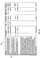
As a result of these impracticalities, few complex system integration projects avail themselves of automated code inspection defect removal strategies, even though applying them to unit tested code prior to beginning system testing is one of the most cost effective options available. This problem has been addressed in part by, e.g., a service provider assembling a set of code inspection tools designed to address four areas, as shown in TABLE 1 below.
TABLE 1
Dynamic
Technologies Static Code Code
Types of analysis: Functional Outputs supported analysis analysis
1 Industry and Best Maintainability, COBOL, C++, X
Practice Standards Robustness, J2EE/JAVA,
Compliance Quality, ABAP,
Changeability, Microsoft.NET
Performance,
Programming
Practices,
Architectural
Design,
Documentation
2 Security Application Web X
Privacy, Applications
Authentication,
Authorization,
Client-side
Attacks,
Command
Execution,
Information
Disclosure,
Location, Logical
Attacks
3 Memory Memory leaks, Web X
Management Memory access Applications
errors, Memory
state tracking,
Quantify for
application
performance
profiling,
Coverage
4 Usability and Accessibility Web X
Accessibility Applications
With this approach, for example, a project (e.g., a software project of an organization) can purchase code inspection services from the service provider on an as-needed basis without requiring any tool purchase or licensing costs for tools they may only need to leverage on a limited basis. Thus, a project may, for example, utilize a plurality of code inspection services (e.g., specifically tailored for their project) and receive code inspection services reports from the service provider. By assembling a set of code inspection tools and providing for purchase of code inspection services on an as-needed basis, utilization of these code inspection services is rendered more cost effective.
However, no defect analysis schema capable of accurately measuring value received from performing specific automated code inspection activities is known to exist. Thus, there is no way to understand the return on this investment (e.g., the purchase of code inspection services) in terms of the impact on reducing the numbers of defects found in late phase testing and in production. That is, the code inspection services reports (for example, from the plurality of code inspection services, e.g., specifically tailored for their project) do not interpret defects uncovered via the automated code inspection subscription service. Rather, such code inspection service reports, for example, only identify defects uncovered via the automated code inspection subscription service. Thus, this automated code inspection subscription service does not allow projects to accurately assess the impact of automated code inspections on, for example, critical exposure areas and does not allow for effective planning of, for example, late phase testing and production support needs.
Accordingly, there exists a need in the art to overcome the deficiencies and limitations described hereinabove.
SUMMARY
In a first aspect of the invention, a method is implemented in a computer infrastructure having computer executable code tangibly embodied on a computer readable storage medium having programming instructions. The programming instructions are operable to receive a tool error output determined by a code inspection tool and select at least one defect classification mapping profile based on the code inspection tool. Additionally, the programming instructions are operable to map the tool error output to one or more output classifications using the selected at least one defect classification mapping profile and generate at least one report based on the one or more output classifications.
In another aspect of the invention, a system comprises an error output receiving tool operable to receive a tool error output determined by a code inspection tool and a selection tool operable to select at least one defect classification mapping profile based on the code inspection tool. Additionally, the system comprises a defect classification mapping tool operable to map the tool error output to one or more output classifications using the selected at least one defect classification mapping profile and a report generation tool operable to generate at least one report based on the one or more output classifications.
In an additional aspect of the invention, a computer program product comprising a computer usable storage medium having readable program code embodied in the medium is provided. The computer program product includes at least one component operable to receive a tool error output determined by a code inspection tool and select at least one defect classification mapping profile based on the code inspection tool. Additionally, the at least one component is operable to map the tool error output to one or more output classifications using the selected at least one defect classification mapping profile and generate at least one defect analysis metric based on the one or more output classifications.
In a further aspect of the invention, a computer system for classifying automated code inspection services defect output for defect analysis, the system comprises a CPU, a computer readable memory and a computer readable storage media. Additionally, the system comprises first program instructions to receive a tool error output determined by a code inspection tool and second program instructions to select at least one defect classification mapping profile based on the code inspection tool. Furthermore, the system comprises third program instructions to map the tool error output to one or more output classifications using the selected at least one defect classification mapping profile and fourth program instructions to generate at least one defect analysis metric based on the one or more output classifications. The first, second, third and fourth program instructions are stored on the computer readable storage media for execution by the CPU via the computer readable memory
BRIEF DESCRIPTION OF THE SEVERAL VIEWS OF THE DRAWINGS
The present invention is described in the detailed description which follows, in reference to the noted plurality of drawings by way of non-limiting examples of exemplary embodiments of the present invention.
FIG. 1 shows an illustrative environment for implementing the steps in accordance with aspects of the invention;
FIG. 2 shows an exemplary depiction of a high level flow in accordance with aspects of the invention;
FIGS. 3-18 illustrate exemplary defect classification mapping profiles for different functional areas of code for a first code inspection service in accordance with aspects of the invention;
FIG. 19 illustrates an exemplary defect classification mapping profile for a second code inspection service in accordance with aspects of the invention;
FIG. 20 illustrates an exemplary defect classification mapping profile for a third code inspection service in accordance with aspects of the present invention;
FIG. 21 illustrates an additional exemplary defect classification mapping profile for a fourth code inspection service in accordance with aspects of the invention;
FIGS. 22-41 illustrate exemplary defect classification mapping profiles which list possible tool error outputs for a fifth code inspection service in accordance with aspects of the invention;
FIG. 42 illustrates an exemplary assessment including a rating of results against expectation for each of technical quality, security, memory and accessibility in accordance with aspects of the present invention;
FIG. 43 illustrates an exemplary quantification of error types in accordance with aspects of the present invention;
FIGS. 44-46 illustrate exemplary histograms in accordance with aspects of the present invention;
FIG. 47 illustrates an exemplary illustration of defect artifact types mapped to a process point when those defects are injected in accordance with aspects of the present invention;
FIGS. 48-58 illustrate additional exemplary histograms in accordance with aspects of the present invention;
FIG. 59 illustrates a trigger summary in accordance with aspects of the invention; and
FIG. 60 shows an exemplary flow for performing aspects of the present invention.
DETAILED DESCRIPTION
The present invention generally relates to defect analysis, and more particularly, to system and method to classify automated code inspection services defect output for defect analysis. The present invention utilizes defect classification field rules (e.g., in accordance with a common schema) for classifying and interpreting defects uncovered via automated code inspection subscription service. More specifically, the present invention establishes automated classification rules to interpret the defects uncovered via various automated code inspection tools (e.g., WebKing®, CAST, Purify Plus™, AppScan®, and ABAP Code Optimizer, amongst other code inspection tools) so that projects can more effectively plan late phase testing needs and reduce high risk or impact defects that would likely otherwise have escaped into production. (Purify Plus and AppScan are trademarks of International Business Machines Corporation in the United States, other countries, or both. WebKing is a trademark of Parasoft Corporation in the United States, other countries, or both.)
Implementing the present invention, leveraging multiple code inspection tools in a defect removal/analysis test service at the unit test phase of the life cycle, enables projects to realize significant cost savings because, for example, finding and fixing high value defects at this relatively early phase (i.e., unit test) is far less expensive than attempting to find and fix defects in any of the late phase tests (e.g., after unit test), or especially in production. The present invention also enables projects to measure the impact of finding and/or fixing these defects on later test phases. For example, if the project has already adequately addressed security concerns in the automated code inspection, the organization can reduce or eliminate test cases from the execution plan and move to production earlier without sacrificing quality or increasing risk.
In embodiments, projects can select any combination of tools to be applied to their code (e.g., WebKing, CAST, Purify Plus, AppScan, and ABAP Code Optimizer). Once the selected tools have been applied to the code under test, the output from the inspection (i.e., from the selected tools) is received by a report generation system including a defect classification mapping tool in accordance with the present invention. As discussed further below, the defect classification mapping tool applies a set of defect classification rules and, in embodiments, a report generation tool produces, for example, an overall defect analysis report based on the output of the defect classification mapping tool.
By implementing the present invention, an organization may allow projects to accurately assess the impact of automated code inspections on critical exposure areas, which can in turn be used to more effectively plan late phase testing and production support needs. For example, the defect analysis report will provide insights that will enable projects to optimize, for example, their go-forward test planning.
System Environment
As will be appreciated by one skilled in the art, the present invention may be embodied as a system, method or computer program product. Accordingly, the present invention may take the form of an entirely hardware embodiment, an entirely software embodiment (including firmware, resident software, micro-code, etc.) or an embodiment combining software and hardware aspects that may all generally be referred to herein as a “circuit,” “module” or “system.” Furthermore, the present invention may take the form of a computer program product embodied in any tangible medium of expression having computer-usable program code embodied in the medium.
Any combination of one or more computer usable or computer readable medium(s) may be utilized. The computer-usable or computer-readable medium may be, for example but not limited to, an electronic, magnetic, optical, electromagnetic, infrared, or semiconductor system, apparatus, device, or propagation medium. More specific examples (a non-exhaustive list) of the computer-readable medium would include the following:
    • an electrical connection having one or more wires,
    • a portable computer diskette,
    • a hard disk,
    • a random access memory (RAM),
    • a read-only memory (ROM),
    • an erasable programmable read-only memory (EPROM or Flash memory),
    • an optical fiber,
    • a portable compact disc read-only memory (CDROM),
    • an optical storage device,
    • a transmission media such as those supporting the Internet or an intranet, or
    • a magnetic storage device.
The computer-usable or computer-readable medium could even be paper or another suitable medium upon which the program is printed, as the program can be electronically captured, via, for instance, optical scanning of the paper or other medium, then compiled, interpreted, or otherwise processed in a suitable manner, if necessary, and then stored in a computer memory.
In the context of this document, a computer-usable or computer-readable medium may be any medium that can contain, store, communicate, propagate, or transport the program for use by or in connection with the instruction execution system, apparatus, or device. The computer-usable medium may include a propagated data signal with the computer-usable program code embodied therewith, either in baseband or as part of a carrier wave. The computer usable program code may be transmitted using any appropriate medium, including but not limited to wireless, wireline, optical fiber cable, RF, etc.
Computer program code for carrying out operations of the present invention may be written in any combination of one or more programming languages, including an object oriented programming language such as JAVA, Smalltalk, C++ or the like and conventional procedural programming languages, such as the “C” programming language or similar programming languages. The program code may execute entirely on the user's computer, partly on the user's computer, as a stand-alone software package, partly on the user's computer and partly on a remote computer or entirely on the remote computer or server. In the latter scenario, the remote computer may be connected to the user's computer through any type of network. This may include, for example, a local area network (LAN) or a wide area network (WAN), or the connection may be made to an external computer (for example, through the Internet using an Internet Service Provider).
FIG. 1 shows an illustrative environment 10 for managing the processes in accordance with the invention. To this extent, the environment 10 includes a server or other computing system 12 that can perform the processes described herein. In particular, the server 12 includes a computing device 14. The computing device 14 can be resident on a network infrastructure or computing device of a third party service provider (any of which is generally represented in FIG. 1). In embodiments, the environment 10 may be designated as a report generation system 210.
The computing device 14 also includes a processor 20, memory 22A, an I/O interface 24, and a bus 26. The memory 22A can include local memory employed during actual execution of program code, bulk storage, and cache memories which provide temporary storage of at least some program code in order to reduce the number of times code must be retrieved from bulk storage during execution. In addition, the computing device includes random access memory (RAM), a read-only memory (ROM), and an operating system (O/S).
The computing device 14 is in communication with the external I/O device/resource 28 and the storage system 22B. For example, the I/O device 28 can comprise any device that enables an individual to interact with the computing device 14 or any device that enables the computing device 14 to communicate with one or more other computing devices using any type of communications link. The external I/O device/resource 28 may be for example, a handheld device, PDA, handset, keyboard etc. In embodiments, the defect classification mapping profiles may be stored in storage system 22B or another storage system, which may be, for example, a database.
In general, the processor 20 executes computer program code (e.g., program control 44), which can be stored in the memory 22A and/or storage system 22B. Moreover, in accordance with aspects of the invention, the program control 44 controls the error output receiving tool 25, the selection tool 30, the defect classification mapping tool 35 and the report generation tool 40. While executing the computer program code, the processor 20 can read and/or write data to/from memory 22A, storage system 22B, and/or I/O interface 24. The program code executes the processes of the invention such as, for example, the processes of the output receiving tool 25, the selection tool 30, the defect classification mapping tool 35 and the report generation tool 40. The bus 26 provides a communications link between each of the components in the computing device 14.
The computing device 14 can comprise any general purpose computing article of manufacture capable of executing computer program code installed thereon (e.g., a personal computer, server, etc.). However, it is understood that the computing device 14 is only representative, of various possible equivalent-computing devices that may perform the processes described herein. To this extent, in embodiments, the functionality provided by the computing device 14 can be implemented by a computing article of manufacture that includes any combination of general and/or specific purpose hardware and/or computer program code. In each embodiment, the program code and hardware can be created using standard programming and engineering techniques, respectively.
Similarly, the computing infrastructure 12 is only illustrative of various types of computer infrastructures for implementing the invention. For example, in embodiments, the server 12 comprises two or more computing devices (e.g., a server cluster) that communicate over any type of communications link, such as a network, a shared memory, or the like, to perform the process described herein. Further, while performing the processes described herein, one or more computing devices on the server 12 can communicate with one or more other computing devices external to the server 12 using any type of communications link. The communications link can comprise any combination of wired and/or wireless links; any combination of one or more types of networks (e.g., the Internet, a wide area network, a local area network, a virtual private network, etc.); and/or utilize any combination of transmission techniques and protocols.
As illustrated in FIG. 1, the error output receiving tool 25 is operable to receive the output of selected code inspection services. Additionally, the selection tool 30 is operable to select an appropriate defect classification mapping profile from a storage system (e.g., storage system 22B) containing classification mapping profiles for each of the code inspection services. Furthermore, the defect classification mapping tool 35 is operable to map the output of the selected code inspection services using the selected defect classification mapping profile(s). The report generation tool 40 is operable to generate a report that includes defect analysis metrics, e.g., the processes described herein. The error output receiving tool 25, the selection tool 30, the defect classification mapping tool 35 and the report generation tool 40 can be implemented as one or more program code in the program control 44 stored in memory 22A as separate or combined modules.
Error Output Receiving Tool
The error output receiving tool 25 is operable to receive the output of selected code inspection services. More specifically, as discussed further below, in embodiments, the output of selected code inspection services will contain, for example, one or more error texts. Each error text may be specific to a particular type of error detected by a particular code inspection service. The error output receiving tool 25 is operable to receive one or more error texts from one or more particular code inspection services, as described further below.
In embodiments, the error output receiving tool 25 is operable to receive an indication of which code inspection tools were utilized in the code inspection services based on the received output of selected code inspection services. Additionally, in embodiments, the error output receiving tool 25 is operable to determine which code inspection tools were utilized in the code inspection services based on the received output of selected code inspection services. For example, in embodiments, the error output receiving tool 25 may access a listing of the different possible outputs of the code inspection services (e.g., error texts) for the different code inspection services (e.g., WebKing, CAST, Purify Plus, AppScan, and ABAP Code Optimizer). The error output receiving tool 25 may compare the output received from the selected code inspection services (e.g., the error texts), for example, for a particular organization's code, to the listing of the different possible outputs to determine which code inspection service or services (e.g., WebKing, CAST, Purify Plus, AppScan, and ABAP Code Optimizer) have been used to test the organization's code. As discussed further below, the determination of which code inspection services have been used to test an organization's code is sent to the selection tool 30 to enable the selection tool 30 to select appropriate defect classification mapping profiles.
Selection Tool
The selection tool 30 is operable to select an appropriate defect classification mapping profile from a defect analysis starter (DAS)/defect reduction method (DRM) storage system 220 (which may be stored in storage system 22B shown in FIG. 1) containing classification mapping profiles for each of the code inspection services. That is, the output of code inspection services, e.g., error texts, may be specific to particular code inspection services. As such, the selection tool 30 is operable to select an appropriate defect classification mapping profile, e.g., one or more defect classification mapping profiles that are specific to the one or more code inspection services used to test code. For example, if the WebKing code inspection tool was used to test, e.g., an organization's code (for example as determined by the error output receiving tool 25), then the selection tool 30 is operable to select one or more defect classification mapping profiles specific to the WebKing code inspection tool. The selected one or more defect classification mapping profiles is utilized by the defect classification mapping tool 35 to enable the defect classification mapping tool 35 to map the output of the selected code inspection services (e.g., the error texts) using the selected defect classification mapping profile(s), as discussed further below.
Mapping Tool
The defect classification mapping tool 35 is operable to map the output of the selected code inspection services using the selected defect classification mapping profile(s), e.g., selected by the selection tool 30. For example, as discussed further below, the defect classification mapping tool 35 may receive the output of selected code inspection services (e.g., from the error output receiving tool 25) and quantify the occurrences of each possible tool error outputs for each of the selected code inspection services.
Additionally, the defect classification mapping tool 35 is operable to map each of the error outputs to its respective classifications (e.g., target, trigger, impact, type, qualifier and severity level, amongst other classifications) using the appropriate defect classification mapping profile defect. Furthermore, the defect classification mapping tool 35 is operable to quantify the defects by one or more of the classifications (e.g., target, trigger, impact, type, qualifier and severity level, amongst other classifications).
Report Generation Tool
In accordance with further aspects of the invention, the report generation tool 40 is operable to generate a report containing, e.g., defect analysis metrics, using the classified tool output information, e.g., received from the defect classification mapping tool 35. In embodiments, the report generation tool 40 may report defect discoveries and provide detailed reports of findings, including mitigated risk. Additionally, the generated reports may be used to analyze and/or measure the results, and highlight error prone areas. Furthermore, the present invention may be used to quantify the extent to which specific defect categories were shifted earlier in the software life cycle (e.g., when defects may be less expensive to remedy), and to identify opportunities to prevent the injection of the high priority defects. A report may include a Rough Order of Magnitude business case reflecting cost reduction opportunity (for example, earlier defect removal, cycle time reduction, and prevention of defect injection).
In embodiments, for example, the report generation tool 40 may provide a report containing an analysis or assessment. The assessment may include for each of technical quality, security, memory and accessibility, a rating of results against expectation and error prone area identification with implications.
Additionally, the report may include an indication of opportunities for improvement. In embodiments, the indication of opportunities for improvement may include trends, implications, opportunities and/or recommendations. Furthermore, the report may include a high level business case including high level cost of initiatives, e.g., reflecting cost reduction opportunity and rough order of magnitude/benefits. Additionally, the report may describe significant and/or critical analysis results, which, for example, may be the metric results rated as the most significant results associated with defect removal (e.g., of the selected one or more code inspection services) and/or in terms of the greatest opportunity to prevent defect injection. The report may also include a histogram of defects found, for example, by tool error category and implications. Exemplary reports in accordance with aspects of the present invention are discussed further below.
Exemplary High Level Flow
FIG. 2 illustrates a high level flow 200 in accordance with aspects of the invention. As shown in FIG. 2, a code inspection service 205 (e.g., an automated code inspection service) is performed on code, e.g., provided by a client, which creates output information (e.g., tool error output 215). As described above, in embodiments, a particular client may use a single automated code inspection service or multiple code inspection services. Additionally, a single code inspection service may comprise multiple code inspection tools (e.g., WebKing, CAST, Purify Plus, AppScan, and ABAP Code Optimizer). The tool error output 215 is received by the report generation system 210 (also shown in FIG. 1).
In embodiments, the report generation system 210 receives the output 215 of selected code inspection services, e.g., using the error output receiving tool 25 (shown in FIG. 1), and accesses one or more appropriate defect classification mapping profiles 217 from a DAS/DRM storage system 220, e.g., using the selection tool 30 (shown in FIG. 1). Additionally, the report generation system 210 maps the output of the selected code inspection services using the selected defect classification mapping profile(s) 217, e.g., using the defect classification mapping tool 35, and generate a report that includes defect analysis metrics, e.g., using the report generation tool 40 (shown in FIG. 1).
For example, as discussed further below, if a WebKing automated code inspection service has been utilized, the report generation system 210 (e.g., the error output receiving tool 25) receives the output 215 of selected code inspection services. Additionally, the report generation system 210 accesses the WebKing defect classification mapping profile(s) 222 from the DAS/DRM storage system 220 (e.g., using the selection tool 30). Utilizing the appropriate defect classification mapping profile(s), the report generation system 210 (e.g., the defect classification mapping tool 35) classifies (or maps) the tool output information (e.g., the tool error output 215). The report generation system 210 (e.g., the report generation tool 40) then uses the classified tool output information to generate a report containing, e.g., defect analysis metrics.
Defect Classification Mapping Profiles
FIGS. 3-41 illustrate exemplary defect classification mapping profiles for five code inspection tools (WebKing, CAST, Purify Plus, AppScan, and ABAP Code Optimizer) in accordance with aspects of the invention. However, these exemplary defect classification mapping profiles should not be considered exhaustive of all defect classification mapping profiles. That is, the invention contemplates that other code inspection tools may be utilized. As such, the invention contemplates that additional defect classification mapping profiles may be tailored to these other code inspection tools. Additionally, while FIGS. 3-41 illustrate exemplary defect classification mapping profiles in a tabular format, the invention contemplates other formats for the defect classification mapping profiles. As such, the exemplary defect classification mapping profiles of FIGS. 3-41 should not be construed as limiting the present invention.
FIGS. 3-18 illustrate exemplary defect classification mapping profiles for different functional areas of code for the WebKing code inspection service. More specifically, FIGS. 3-18 illustrate exemplary defect classification mapping profiles for a WebKing error output (e.g., one of the tools included in the code inspection service) to five specific Defect Reduction Method (DRM) fields/attributes: trigger, target, impact, type and qualifier, and a severity level.
A “trigger” indicates how a defect was discovered (e.g., the circumstances surrounding the defect discovery). A “target” indicates a high level cause of the defect. As with the present invention, the code inspection services identify code defects, for each of the exemplary defect classification mapping profiles, the target should be “requirements/design/code.” An “impact” indicates an impact to a user. For example, “accessibility” indicates whether a handicapped individual can attain access.
A “type” (or “artifact type”) indicates what was fixed, specifying, for example, the size and complexity of what was fixed. For example, were just a few lines of code fixed or was a large amount of code fixed. Exemplary types include “assignment,” indicating a simple fix, “checking,” indicating a more complex fix, and “algorithm,” which is more complex than both the assignment and checking types. A “qualifier” indicates whether errors found are related to, e.g., incorrect, extraneous or missing code. In accordance with aspects of the invention, by combining the type and qualifier, the present invention is able to determine where an error was injected into the project. A “severity” indicates a relative severity of the error. In embodiments, depending upon which code inspection services are utilized by a client, the severity may have a value of between 1 (most severe) and 3 (least severe), with other severity levels contemplated by the invention. The severity may provide insight, for example, as to where processes may be weak.
FIG. 3 shows an exemplary defect classification mapping profile 300 for “Images and Animations” functional area of a WebKing code inspection service. As shown in FIG. 3, exemplary defect classification mapping profile 300 includes a tool error output column 305, which lists possible tool error outputs 310 (e.g., error text). As should be understood, the list of possible tool error outputs 310 is not exhaustive, and the invention contemplates that other possible tool error outputs may also be included in a defect classification mapping profile, in accordance with aspects of the invention. For example, in embodiments, the list of possible tool error outputs 310 may be dynamic, such that new possible tool error outputs may be added to the tool error output column 305.
Additionally, the invention contemplates that a particular tool error output for a particular code inspection tool representative of a particular code defect may change. For example, newer versions of a code inspection tool may identify a defect by with a new tool error output (as compared to an older version of the code inspection tool). As such, the list of possible tool error outputs 310 is not exhaustive, and the invention contemplates that other possible tool error outputs may also be included in a defect classification mapping profile, in accordance with aspects of the invention.
As shown in FIG. 3, with defect classification mapping profile 300 each of the possible tool error outputs 310 (e.g., error texts) include an acronym 315, text 320 and bracketed information 325. The acronym 315 (e.g., “SV,” “PSV” or “V”) indicates whether the defect is a severe violation, possible severe violation or a violation, respectively. The text 320 indicates some corrective action and the bracketed information 325 provides code location information (e.g., pointing a programmer to the appropriate section of code containing the identified error). As those of ordinary skill in the art would readily understand the information contained in the tool error output column 305, no further explanation is necessary for an understanding of the present invention.
Additionally, FIG. 3 includes a tool error output classification 330 for each of the possible tool error outputs 310 (e.g., error texts). More specifically, the exemplary defect classification mapping profile 300 includes a target/trigger/impact column 335, which indicates the target, the trigger and the impact for each of the possible tool error outputs 310. As shown in FIG. 3, as with the present invention, the code inspection services identify code defects, for each of the exemplary defect classification mapping profiles, the target will be “requirements/design/code.” Moreover, as indicated in FIG. 3, for each of the “Images and Animations” tool error output, the trigger is “variation” and the impact is “accessibility.” As should be understood, while illustrated as a single column, target/trigger/impact column 335 may be depicted as, e.g., three discrete columns.
The exemplary defect classification mapping profile 300 includes a type column 340, which indicates what was fixed, specifying, for example, the size and complexity of what was fixed. As indicated in FIG. 3, types for this exemplary defect classification mapping profile 300 include “assignment,” and “algorithm.” As discussed above, “assignment,” indicates, for example, a simple fix, whereas “algorithm” indicates, for example, a more complex fix. Additionally, the exemplary defect classification mapping profile 300 includes a qualifier column 345, indicating whether the error found is related to, e.g., incorrect, extraneous or missing code. The exemplary defect classification mapping profile 300 further includes a severity column 350, which indicates a relative severity of the error. In embodiments, depending upon which code inspection services are utilized by a client, the severity may have a value of between 1 (most severe) and 3 (least severe), with other severity values contemplated by the invention.
In accordance with aspects of the invention, the values for the tool error output classification 330 (e.g., the values of columns 335, 340, 345 and 350) have been determined for each of the possible tool error outputs 310. More specifically, values for the tool error output classification 330 have been determined based on review of historical code defects (e.g., contained in a defect analysis starter/defect reduction method (DAS/DRM) project repository) and, for example, patterns discovered from the historic code defects. That is, as described above, after a defect has been fixed, data regarding the defect (e.g., target, trigger, impact, type and qualifier), and the resolution of the defect, may be stored in a database. For example, the database of past defects (which include, for example, for each defect an indication of the defect's target, trigger, impact, type and qualifier) may be used to determine associations between each possible tool error output 310 and their respective tool output classifications (e.g., target, trigger, impact, type, qualifier and severity level, amongst other classifications), as exemplified by defect classification mapping profile 300.
Additionally, in accordance with aspects of the present invention, with exemplary defect classification mapping profile 300 values for the severity column 350 may be derived from the acronym 315 (e.g., “SV,” “PSV” or “V”). For example, a tool error output 305 indicating a severe violation (SV) is assigned a severity level of “1,” whereas a possible severe violation (PSV) is assigned a severity level of “2,” and a violation (V) is assigned a severity level of “3.”
While the exemplary defect classification mapping profile 300 includes a listing of possible tool error outputs 310 for each code inspection service, the invention contemplates that additional possible tool error outputs 310 may arise. For example, a particular code inspection service may designate a new tool error output. As such, the exemplary defect classification mapping profile 300 (or any other defect classification mapping profile) should not be construed as limiting the present invention.
FIGS. 4-18 illustrate additional exemplary defect classification mapping profiles 400-1800, which list additional possible tool error outputs for different functional areas (e.g., non-text content, image maps, captions, etc.) of the WebKing code inspection service. Each of the additional exemplary defect classification mapping profiles 400-1800 are derived and used in a similar manner to exemplary defect classification mapping profile 300. However, as explained above, each of the exemplary defect classification mapping profiles 400-1800 are for different functional areas of the WebKing code inspection service. As such, each of the exemplary defect classification mapping profiles 400-1800 may have different possible tool error outputs 310 (e.g., error texts). As each of the additional exemplary defect classification mapping profiles 400-1800 are derived and used in a similar manner to exemplary defect classification mapping profile 300, a further description of FIGS. 4-18 is not necessary for those of ordinary skill in the art to practice the invention.
FIG. 19 illustrates an additional exemplary defect classification mapping profile 1900 for the Purify Plus code inspection service. The exemplary defect classification mapping profile 1900 is derived and used in a similar manner to exemplary defect classification mapping profiles 300-1800. However, as explained above, exemplary defect classification mapping profile 1900 is for the Purify Plus code inspection service. As such, exemplary defect classification mapping profile 1900 may have different possible tool error outputs 310. Additionally, exemplary defect classification mapping profile 1900 includes a separate column for trigger, as the trigger varies depending on the tool error output 310. As exemplary defect classification mapping profile 1900 is derived and used in a similar manner to exemplary defect classification mapping profiles 300-1800, a further description of FIG. 19 is not necessary for those of ordinary skill in the art to practice the invention.
FIG. 20 illustrates an additional exemplary defect classification mapping profile 2000 for the ABAP Code Optimizer code inspection service. The exemplary defect classification mapping profile 2000 is derived and used in a similar manner to exemplary defect classification mapping profiles 300-1900. However, as explained above, exemplary defect classification mapping profile 2000 is for the ABAP Code Optimizer code inspection service. As such, exemplary defect classification mapping profile 2000 may have different possible tool error outputs 310. Additionally, exemplary defect classification mapping profile 2000 includes additional classifications (e.g., category and sub-category). As exemplary defect classification mapping profile 2000 is derived and used in a similar manner to exemplary defect classification mapping profiles 300-1900, a further description of FIG. 20 is not necessary for those of ordinary skill in the art to practice the invention.
FIG. 21 illustrates an additional exemplary defect classification mapping profile 2100 for of the APPScan code inspection service. The exemplary defect classification mapping profile 2100 is derived and used in a similar manner to exemplary defect classification mapping profiles 300-2000. However, as explained above, exemplary defect classification mapping profile 2100 is for the APPScan code inspection service. As such, exemplary defect classification mapping profile 2100 may have different possible tool error outputs 310. As exemplary defect classification mapping profile 2100 is derived and used in a similar manner to exemplary defect classification mapping profiles 300-2000, a further description of FIG. 21 is not necessary for those of ordinary skill in the art to practice the invention.
FIGS. 22-41 illustrate exemplary defect classification mapping profiles 2200-4100, which list possible tool error outputs for the CAST code inspection service. Each of the exemplary defect classification mapping profiles 2200-4100 are derived and used in a similar manner to exemplary defect classification mapping profiles 300-2100. However, each of the exemplary defect classification mapping profiles 2200-4100 is for the CAST code inspection service. As such, for example as shown in FIG. 22, each of the exemplary defect classification mapping profiles 2200-4100 may have different possible tool error outputs 310. As each of the exemplary defect classification mapping profiles 2200-4100 are derived and used in a similar manner to exemplary defect classification mapping profiles 300-2100, a further description of FIGS. 22-41 is not necessary for those of ordinary skill in the art to practice the invention.
As can be observed from the exemplary defect classification mapping profiles 300-4100 and as discussed further below, the present invention is operable to translate the outputs of the different code inspection services to one or more standardized metrics, e.g., in accordance with a common schema. That is, for each of the different possible code error outputs of the different code inspection services, as shown in FIGS. 3-41, the DAS/DRM defect profiles 300-4100 indicate metrics, e.g., severity, target, trigger, impact, type and qualifier, in accordance with the common schema. In this way, the classification mapping of the present invention enables defect analysis reporting, e.g., of the metrics, of defects identified, for example, from different code inspection tools.
Exemplary Reports
FIGS. 42-59 illustrate exemplary reports (or components of a report) in accordance with aspects of the invention. However, these exemplary reports should not be considered as exhaustive of all reports contemplated by the invention. That is, the invention contemplates that the report generation tool 40 may generate other reports. Additionally, while FIGS. 44-58 illustrate exemplary reports as histograms, the invention contemplates other formats for the reports. As such, the exemplary reports (or components of reports) of FIGS. 42-59 should not be construed as limiting the present invention. In embodiments, the present invention is operable to transform the output 215 of selected code inspection services to one or more reports that include defect analysis metrics.
As discussed above, in embodiments, for example, the report generation tool 40 may provide a report containing an analysis or assessment. The assessment may include for each of technical quality, security, memory and accessibility, a rating of results against expectation and error prone area identification with implications. In embodiments, the present invention is operable to manipulate, e.g., map, the output of the selected code inspection services using the selected defect classification mapping profile(s) 217 to generate the report that includes defect analysis metrics, e.g., using the report generation tool 40 (shown in FIG. 1). FIG. 42 illustrates an exemplary assessment 4200 including a rating of results 4205 against expectation 4210 for each of technical quality, security, memory and accessibility. FIG. 43 illustrates an exemplary quantification of error types (e.g., technical quality, security, memory and accessibility) in terms of KLOC (thousand of lines of code) and percentage of total errors.
FIG. 44 illustrates an exemplary histogram 4400 of defects found by tool error category, and implications. In accordance with aspects of the invention, the report generation tool 40 may generate a histogram, e.g., exemplary histogram 4400 of defects found by tool error category, and implications, as a report or as a component of a report. Additionally, in embodiments, the histogram 4400 may indicate subcategories, if they are defined. More specifically, FIG. 44 illustrates a quantification of accessibility defects found using a particular code inspection service for two rules and/or industry standards (e.g., “Standard/Rule 1” and “Standard/Rule 2”). Accessibility errors, for example, may relate to a standard of rules for handicapped, disabled or senior users. The different possible defects (e.g., frames, forms, captions, etc.) are listed in the table key 4410 and identified by, e.g., different pattern and/or shades. Thus, as can be observed in exemplary histogram 4400, with Standard/Rule 1, approximately fifty-three errors are detected and with Standard/Rule 2, approximately fifteen errors are detected.
While exemplary histogram 4400 quantifies defects found by tool error category, and implication, this information is limited to what an automated tool can look for. Additionally, exemplary histogram 4400 may not allow for any conclusions (e.g., future planning) as no particular defect significantly stands out more than any other defect.
FIG. 45 illustrates an exemplary histogram of defects by severity 4500. More specifically, FIG. 45 illustrates the errors detected as shown in FIG. 44, however, the errors are now quantified by severity level, e.g., severity 1, 2 or 3, (as determined by the defect classification mapping tool 35). In accordance with aspects of the invention, by quantifying (and presenting in a report) the detected errors identified by severity level, for example, as illustrated in FIG. 45, the present invention may be used to identify opportunities, e.g., to prevent the injection of defects, as discussed further below.
FIG. 46 illustrates an exemplary histogram of defects 4600 by DRM artifact type (e.g., checking, algorithm/method, or assignment/initialization) and qualifier (e.g., incorrect or missing) in accordance with aspects of the invention. More specifically, FIG. 46 illustrates the errors detected as shown in FIG. 44, however, the same errors are now quantified by DRM artifact type and qualifier, (as determined by the defect classification mapping tool 35).
In accordance with aspects of the invention, by quantifying (and presenting in a report) the detected errors identified by DRM artifact type and qualifier, for example, as illustrated in FIG. 46, the present invention may be used to identify opportunities, e.g., to prevent the injection of defects. With an understanding of how past defects (as detected by the code inspection tools) were injected into the software code lifecycle, an organization may discover opportunities for preventing the injection of future defects. For example, as shown in FIG. 46, a majority of the algorithm/method type defects have a “missing” defect qualifier. Conversely, with the example of FIG. 46, a majority of the checking type defects have an “incorrect” defect qualifier. In accordance with aspects of the invention, this information may be used to discover opportunities for preventing the injection of future defects, e.g., adjusting staffing levels and/or review processes.
FIG. 47 illustrates an exemplary illustration of table 4700 of defect artifact types mapped to a process point when those defects are injected. In embodiments, table 4700 may be used to identify defect prevention opportunities. As shown in FIG. 47, table 4700 includes column 4705 listing the generic process areas in the software development life cycle when particular defects may be injected. As illustrated in FIG. 4700, the lowest process area, “code,” is later in the life cycle and the highest process area, “high level requirements,” is earlier in the life cycle. Table 4700 additionally includes qualifier column 4710 indicating a defect qualifier (e.g., missing or incorrect) and a type column 4715 indicating a defect type (e.g., relationship, checking, etc.).
Table 4700 indicates earlier process areas 4720 and later process areas 4725. Earlier process areas 4720 include defects that are only found by a user evaluating function in relatively sophisticated ways. As such, an automated code inspection tool would not discover these types of defects. In contrast, later process areas 4725 include defects uncovered using an automated code inspection tool. In accordance with aspects of the invention, in embodiments, the report generation tool is operable to map defects by artifact type, qualifier and/or process area.
With an understanding of how past defects (as detected by the code inspection tools) were injected into the software code lifecycle, an organization may discover opportunities for preventing the injection of further defects. For example, “missing algorithms” and “missing checking” may each indicate weaknesses existed in the low level (or detailed) requirements development and/or process. Additionally, for example “incorrect assignments” and “incorrect checking” indicate coding oversights. “Missing assignments” indicates coding oversights as well. Static testing methods, such as code inspection services, unit testing and/or code inspections, could be used to remove such coding oversights earlier in the life cycle (thus, reducing costs).
FIG. 48 illustrates an exemplary histogram 4800 of memory defects found using a particular code inspection service (e.g., Purify Plus) by severity level. As shown in FIG. 48, histogram 4800 quantifies occurrences of each of the possible tool error outputs 310 for the Purify Plus code inspection tool. Moreover, histogram 4800 indicates the number of defects by severity level. As can be observed, with exemplary histogram 4800 all of the errors are “Severity 1.”
FIG. 49 illustrates an exemplary histogram of memory defects 4900 by DRM artifact type (e.g., checking, algorithm/method, or assignment/initialization) and qualifier (e.g., incorrect or missing) in accordance with aspects of the invention. FIG. 49 is similar to FIG. 46, described above. As such, further description of FIG. 49 is not necessary for those of skill in the art to practice the present invention, but for further elucidation, pertinent portions of the figures are discussed herein. In accordance with aspects of the invention, by quantifying (and presenting in a report) the detected errors identified by DRM artifact type and qualifier, for example, as illustrated in FIG. 49, the present invention may be used to identify opportunities, e.g., to prevent the injection of defects. With an understanding of how past defects (as detected by the code inspection tools) were injected into the software code lifecycle, an organization may discover opportunities for preventing the injection of future defects. For example, as shown in FIG. 49, all of the defects have a “missing” defect qualifier. In accordance with aspects of the invention, this information may be used to discover opportunities for preventing the injection of future defects, e.g., adjusting staffing levels and/or review processes.
FIG. 50 illustrates an exemplary histogram 5000 of defects found by tool error category, and implications. In accordance with aspects of the invention, the report generation tool 40 may generate a histogram, e.g., exemplary histogram 5000 of defects found by tool error category, and implications, as a report or as a component of a report. Additionally, in embodiments, the histogram 5000 may indicate defect subcategories, if they are defined (for example, as listed in the table key 5010 and identified by, e.g., different pattern and/or shades). More specifically, FIG. 50 illustrates a quantification of security defects found using a particular code inspection service. As shown in FIG. 50, the most frequent security defects (e.g., as determined by a code inspection service) are “Information Disclosure” security defects. Additionally, for each defect type, exemplary histogram 5000 indicates security defect subcategories.
FIG. 51 illustrates an exemplary histogram of security defects by severity 5100. More specifically, FIG. 51 illustrates the errors detected as shown in FIG. 50, however, the errors are now quantified by severity level, e.g., severity 1, 2, 3 or 4 (as determined by the defect classification mapping tool 35). In accordance with aspects of the invention, by quantifying (and presenting in a report) the detected errors identified by severity level, for example, as illustrated in FIG. 51, the present invention may be used to identify opportunities, e.g., to prevent the injection of defects.
FIG. 52 illustrates an exemplary histogram of security defects by DRM artifact type (e.g., checking, algorithm/method, or assignment/initialization, etc.) and qualifier (e.g., incorrect or missing) in accordance with aspects of the invention. FIG. 52 is similar to FIGS. 46 and 49, described above. As such, further description of FIG. 52 is not necessary for those of skill in the art to practice the present invention, but for further elucidation, pertinent portions of the figures are discussed herein. In accordance with aspects of the invention, by quantifying (and presenting in a report) the detected security errors identified by DRM artifact type and qualifier, for example, as illustrated in FIG. 52, the present invention may be used to identify opportunities, e.g., to prevent the injection of defects. For example, as shown in FIG. 52, most of the security defects have a “missing” defect qualifier. In accordance with aspects of the invention, this information may be used to discover opportunities for preventing the injection of future security defects, e.g., adjusting staffing levels and/or review processes.
FIGS. 53-55 illustrate exemplary histogram 5300 of technical quality defects found by tool error category, and implications, exemplary histogram 5400 of technical quality defects by severity and exemplary histogram of technical quality defects by DRM artifact type (e.g., checking, algorithm/method, or assignment/initialization, etc.) and qualifier (e.g., incorrect or missing) in accordance with aspects of the invention As FIGS. 53-55 are similar to FIGS. 50-52, described above, a further description of FIGS. 53-55 is not necessary for those of skill in the art to practice the invention.
FIG. 56 illustrates an exemplary summary metrics histogram 5600 indicating a quantification of defect types. Additionally, histogram 5600 indicates, for each defect type, (e.g., transferability, security, etc.), the number of errors for each severity level (e.g., “Severity 1,” “Severity 2,” etc.), as indicated by key 5610.
FIG. 57 illustrates an exemplary summary metrics histogram 5700 indicating a quantification of defects in the four analysis areas (e.g., technical quality, security, accessibility and memory) for the different stages of the software development life cycle (e.g., high level requirements, detailed design, etc.), as indicated by key 5710. FIG. 58 illustrates an exemplary summary metrics histogram 5800 indicating a quantification of defects as a percentage of total defects in the four analysis areas (e.g., technical quality, security, accessibility and memory) for the different stages of the software development life cycle (e.g., high level requirements, detailed design, etc.), as indicated by key 5710.
FIG. 59 illustrates a trigger summary 5900 in accordance with aspects of the invention. As shown in FIG. 59, the trigger summary 5900 includes an analysis area column 5905 indicating the analysis area (e.g., accessibility, memory, technical quality, and security). Additionally, the trigger summary 5900 includes a trigger column 5910 listing the detected defect triggers (e.g., as determined from the code inspection service) and a severity level column 5915 listing the severities for each of the defect triggers (e.g., as determined by the defect classification mapping tool 35). The trigger summary 5900 also includes a frequency column 5920 which indicates a quantification of detected code defects by trigger and severity.
Flow Diagram
FIG. 60 shows an exemplary flow for performing aspects of the present invention. The steps of FIG. 60 may be implemented in the environment of FIG. 1, for example. The flow diagram may equally represent a high-level block diagram or a swim-lane diagram of the invention. The flowchart and/or block diagram in FIG. 60 illustrates the architecture, functionality, and operation of possible implementations of systems, methods and computer program products according to various embodiments of the present invention. In this regard, each block in the flowchart, block diagram or swim-lane diagram may represent a module, segment, or portion of code, which comprises one or more executable instructions for implementing the specified logical function(s). It should also be noted that, in some alternative implementations, the functions noted in the blocks may occur out of the order noted in the figure. For example, two blocks shown in succession may, in fact, be executed substantially concurrently, or the blocks may sometimes be executed in the reverse order, depending upon the functionality involved. Each block of each flowchart, and combinations of the flowchart illustration can be implemented by special purpose hardware-based systems that perform the specified functions or acts, or combinations of special purpose hardware and computer instructions and/or software, as described above. Moreover, the steps of the flow diagram may be implemented and executed from either a server, in a client server relationship, or they may run on a user workstation with operative information conveyed to the user workstation. In an embodiment, the software elements include firmware, resident software, microcode, etc.
In embodiments, a service provider, such as a Solution Integrator, could offer to perform the processes described herein. In this case, the service provider can create, maintain, deploy, support, etc., the computer infrastructure that performs the process steps of the invention for one or more customers. These customers may be, for example, any business that uses technology. In return, the service provider can receive payment from the customer(s) under a subscription and/or fee agreement and/or the service provider can receive payment from the sale of advertising content to one or more third parties.
Furthermore, the invention can take the form of a computer program product accessible from a computer-usable or computer-readable medium providing program code for use by or in connection with a computer or any instruction execution system. The software and/or computer program product can be implemented in the environment of FIG. 1. For the purposes of this description, a computer-usable or computer readable medium can be any apparatus that can contain, store, communicate, propagate, or transport the program for use by or in connection with the instruction execution system, apparatus, or device. The medium can be an electronic, magnetic, optical, electromagnetic, infrared, or semiconductor system (or apparatus or device) or a propagation medium. Examples of a computer-readable storage medium include a semiconductor or solid state memory, magnetic tape, a removable computer diskette, a random access memory (RAM), a read-only memory (ROM), a rigid magnetic disk and an optical disk. Current examples of optical disks include compact disk-read only memory (CD-ROM), compact disc-read/write (CD-R/W) and DVD.
As shown in FIG. 6000, at step 6005, an error output receiving tool receives the code inspection service tool error output determined from testing, e.g., an organization's code. At step 6010, the selection tool selects one or more appropriate defect classification mapping profiles based on which code inspection service(s) was (or were) utilized to test code. For example, if a WebKing automated code inspection service has been utilized, the present invention accesses the WebKing defect classification mapping profile(s).
At step 6015, the defect classification mapping tool maps errors of the tool error output to the selected one or more defect classification mapping profiles. For example, the defect classification mapping tool may quantify the occurrences of each possible tool error outputs for each of the selected code inspection services and map each of the error outputs to its respective classifications (e.g., target, trigger, impact, type, qualifier and severity level, amongst other classifications) using the appropriate defect classification mapping profile defect. At step 6020, the report generation tool generates one or more reports based on the mapping of the tool error output to the selected one or more defect classification mapping profiles, for example, a report containing, e.g., defect analysis metrics.
The terminology used herein is for the purpose of describing particular embodiments only and is not intended to be limiting of the invention. As used herein, the singular forms “a”, “an” and “the” are intended to include the plural forms as well, unless the context clearly indicates otherwise. It will be further understood that the terms “comprises” and/or “comprising,” when used in this specification, specify the presence of stated features, integers, steps, operations, elements, and/or components, but do not preclude the presence or addition of one or more other features, integers, steps, operations, elements, components, and/or groups thereof.
The corresponding structures, materials, acts, and equivalents of all means or step plus function elements in the claims, if applicable, are intended to include any structure, material, or act for performing the function in combination with other claimed elements as specifically claimed. The description of the present invention has been presented for purposes of illustration and description, but is not intended to be exhaustive or limited to the invention in the form disclosed. Many modifications and variations will be apparent to those of ordinary skill in the art without departing from the scope and spirit of the invention. The embodiment was chosen and described in order to best explain the principals of the invention and the practical application, and to enable others of ordinary skill in the art to understand the invention for various embodiments with various modifications as are suited to the particular use contemplated. Accordingly, while the invention has been described in terms of embodiments, those of skill in the art will recognize that the invention can be practiced with modifications and in the spirit and scope of the appended claims.

Claims (25)

What is claimed is:
1. A method implemented in a computer infrastructure having computer executable code tangibly embodied on a computer readable storage memory having programming instructions operable to:
receive a tool error output determined by a code inspection service;
determine an identification of a code inspection tool used by the code inspection service to generate the tool error output;
select at least one defect classification mapping profile that is specific to the identified code inspection tool;
map the tool error output to one or more output classifications using the selected at least one defect classification mapping profile; and
generate at least one report based on the one or more output classifications,
wherein the determining the identification of the code inspection tool used by the code inspection service to generate the tool error output comprises comparing the tool error output received from the code inspection service to a listing of possible error outputs for a plurality of code inspection tools; and
the selecting the at least one defect classification mapping profile that is specific to the identified code inspection tool comprises selecting the at least one defect classification mapping profile from a defect analysis storage system comprising a plurality of classification mapping profiles for each of the plurality of code inspection tools.
2. The method of claim 1, wherein the code inspection tool comprises at least one of a plurality of code inspection tools.
3. The method of claim 1, wherein the one or more output classifications comprise at least one of: a target, a trigger, an impact, a type, a qualifier and a severity.
4. The method of claim 3, wherein:
the target indicates a high level cause of a defect;
the trigger indicates at least one of how the defect was discovered and circumstances surrounding a defect discovery;
the impact indicates an impact to a user;
the type indicates a size and complexity of a fix for the defect;
the qualifier indicates whether the defect is related to incorrect, extraneous or missing code; and
the severity indicates a relative severity of the defect.
5. The method of claim 1, wherein each defect classification mapping profile for a particular code inspection tool comprises:
a listing of possible tool error outputs for the particular code inspection tool; and
corresponding output classifications for each of the possible tool error outputs.
6. The method of claim 5, wherein:
the listing of possible tool error outputs for each particular code inspection tool are different from one another; and
the output classifications for each of the particular code inspection tools utilize a common classification schema.
7. The method of claim 6, wherein the selecting the at least one defect classification mapping profile that is specific to the identified code inspection tool comprises selecting one or more designated defect classification mapping profiles, which each comprise:
the listing of possible tool error outputs for the particular code inspection tool; and
for each of the possible tool error outputs, a corresponding output classification with the common classification schema.
8. The method of claim 1, wherein:
the tool error output comprises one or more error texts; and
the mapping the tool error output to one or more output classifications using the selected at least one defect classification mapping profile comprises for each of the one or more error texts, determining a corresponding output classification.
9. The method of claim 8, wherein the corresponding output classification comprises at least one of a corresponding target, a corresponding trigger, a corresponding impact, a corresponding type, a corresponding qualifier and a corresponding severity in accordance with a common classification schema.
10. The method of claim 1, wherein the tool error output identifies at least one code defect which is at least one of an accessibility defect, a memory defect, a security defect and a technical quality defect.
11. The method of claim 1, wherein the at least one report based on the one or more output classifications indicates at least one of:
defect analysis metrics; and
opportunities for preventing the injection of defects.
12. The method of claim 1, wherein the at least one report based on the one or more output classifications quantifies defects by error type and severity.
13. The method of claim 1, wherein the at least one report based on the one or more output classifications comprises a trigger summary including a quantification of at least one of accessibility defects, memory defects, security defects and technical quality defects by trigger and severity.
14. The method of claim 1, wherein a service provider at least one of creates, maintains, deploys and supports the computer infrastructure.
15. The method of claim 1, wherein steps are provided by a service provider on a subscription, advertising, and/or fee basis.
16. A system, comprising:
an error output receiving tool implemented in a processor and operable to:
receive a tool error output determined by a code inspection service, and
determine an identification of a code inspection tool used by the code inspection service to generate the tool error output;
a selection tool operable to select at least one defect classification mapping profile that is specific to the identified code inspection tool;
a defect classification mapping tool operable to map the tool error output to one or more output classifications using the selected at least one defect classification mapping profile; and
a report generation tool operable to generate at least one report based on the one or more output classifications,
wherein the determining the identification of the code inspection tool used by the code inspection service to generate the tool error output comprises comparing the tool error output received from the code inspection service to a listing of possible error outputs for a plurality of code inspection tools; and
the selecting the at least one defect classification mapping profile that is specific to the identified code inspection tool comprises selecting the at least one defect classification mapping profile from a defect analysis storage system comprising a plurality of classification mapping profiles for each of the plurality of code inspection tools.
17. The system of claim 16, wherein:
the one or more output classifications comprise at least one of: a target, a trigger, an impact, a type, a qualifier and a severity;
each defect classification mapping profile for a particular code inspection tool comprises:
a listing of possible tool error outputs for the particular code inspection tool; and
corresponding output classifications for each of the possible tool error outputs;
the listing of possible tool error outputs for each particular code inspection tool are different from one another; and
the output classifications for each of the particular code inspection tools utilize a common classification schema.
18. The system of claim 17, wherein:
the target indicates a high level cause of a defect;
the trigger indicates at least one of how the defect was discovered and circumstances surrounding a defect discovery;
the impact indicates an impact to a user;
the type indicates a size and complexity of a fix for the defect;
the qualifier indicates whether the defect is related to incorrect, extraneous or missing code; and
the severity indicates a relative severity of the defect.
19. The system of claim 16, wherein:
the tool error output comprises one or more error texts,
the defect classification mapping tool is further operable to, for each of the one or more error texts, determine a corresponding output classification, and
the corresponding output classification comprises at least one of a corresponding target, a corresponding trigger, a corresponding impact, a corresponding type, a corresponding qualifier and a corresponding severity in accordance with a common classification schema.
20. The system of claim 16, wherein the one or more output classifications comprise at least one of: a target, a trigger, an impact, a type, a qualifier and a severity.
21. The system of claim 16, wherein the at least one report based on the one or more output classifications indicates at least one of:
defect analysis metrics; and
opportunities for preventing the injection of defects.
22. The system of claim 16, wherein the at least one report based on the one or more output classifications quantifies defects by error type and severity.
23. The system of claim 16, wherein the at least one report based on the one or more output classifications comprises a trigger summary including a quantification of at least one of accessibility defects, memory defects, security defects and technical quality defects by trigger and severity.
24. A computer program product comprising a computer readable storage memory having readable program code embodied in the storage memory, the computer program product includes at least one component operable to:
receive a tool error output determined by a code inspection service;
compare the tool error output received from the code inspection service to a listing of possible error outputs for a plurality of code inspection tools to determine an identification of a code inspection tool used by the code inspection service to generate the tool error output;
select at least one defect classification mapping profile that is specific to the identified code inspection tool;
map the tool error output to one or more output classifications using the selected at least one defect classification mapping profile; and
generate at least one defect analysis metric based on the one or more output classifications,
wherein the selecting the at least one defect classification mapping profile that is specific to the identified code inspection tool comprises selecting the at least one defect classification mapping profile from a defect analysis storage system comprising a plurality of classification mapping profiles for each of the plurality of code inspection tools.
25. A computer system for classifying automated code inspection services defect output for defect analysis, the system comprising:
a CPU, a computer readable memory and a computer readable storage media;
first program instructions to receive a tool error output determined by at least one code inspection service;
second program instructions to compare the tool error output received from the at least one code inspection service to a listing of possible error outputs for a plurality of code inspection tools used by the at least one code inspection service;
third program instructions to determine an identification of at least one code inspection tool used by the at least one code inspection service to generate the tool error output;
fourth program instructions to select at least one defect classification mapping profile that is specifically designed to respectively map the tool error output for the identified at least code inspection tool to one or more output classifications;
fifth program instructions to map the tool error output to the one or more output classifications using the selected at least one defect classification mapping profile; and
sixth program instructions to generate at least one defect analysis metric based on the one or more output classifications,
wherein the first through sixth program instructions are stored on the computer readable storage media for execution by the CPU via the computer readable memory; and
the selecting the at least one defect classification mapping profile that is specifically designed to respectively map the tool error output comprises selecting the at least one defect classification mapping profile from a defect analysis storage system comprising a plurality of classification mapping profiles for each of the plurality of code inspection tools.
US12/558,274 2009-09-11 2009-09-11 System and method to classify automated code inspection services defect output for defect analysis Expired - Fee Related US8527955B2 (en)

Priority Applications (5)

Application Number Priority Date Filing Date Title
US12/558,274 US8527955B2 (en) 2009-09-11 2009-09-11 System and method to classify automated code inspection services defect output for defect analysis
US13/923,581 US8924936B2 (en) 2009-09-11 2013-06-21 System and method to classify automated code inspection services defect output for defect analysis
US14/510,296 US9176844B2 (en) 2009-09-11 2014-10-09 System and method to classify automated code inspection services defect output for defect analysis
US14/844,422 US9442821B2 (en) 2009-09-11 2015-09-03 System and method to classify automated code inspection services defect output for defect analysis
US15/215,664 US9753838B2 (en) 2009-09-11 2016-07-21 System and method to classify automated code inspection services defect output for defect analysis

Applications Claiming Priority (1)

Application Number Priority Date Filing Date Title
US12/558,274 US8527955B2 (en) 2009-09-11 2009-09-11 System and method to classify automated code inspection services defect output for defect analysis

Related Child Applications (1)

Application Number Title Priority Date Filing Date
US13/923,581 Continuation US8924936B2 (en) 2009-09-11 2013-06-21 System and method to classify automated code inspection services defect output for defect analysis

Publications (2)

Publication Number Publication Date
US20110067006A1 US20110067006A1 (en) 2011-03-17
US8527955B2 true US8527955B2 (en) 2013-09-03

Family

ID=43731728

Family Applications (5)

Application Number Title Priority Date Filing Date
US12/558,274 Expired - Fee Related US8527955B2 (en) 2009-09-11 2009-09-11 System and method to classify automated code inspection services defect output for defect analysis
US13/923,581 Active US8924936B2 (en) 2009-09-11 2013-06-21 System and method to classify automated code inspection services defect output for defect analysis
US14/510,296 Expired - Fee Related US9176844B2 (en) 2009-09-11 2014-10-09 System and method to classify automated code inspection services defect output for defect analysis
US14/844,422 Expired - Fee Related US9442821B2 (en) 2009-09-11 2015-09-03 System and method to classify automated code inspection services defect output for defect analysis
US15/215,664 Expired - Fee Related US9753838B2 (en) 2009-09-11 2016-07-21 System and method to classify automated code inspection services defect output for defect analysis

Family Applications After (4)

Application Number Title Priority Date Filing Date
US13/923,581 Active US8924936B2 (en) 2009-09-11 2013-06-21 System and method to classify automated code inspection services defect output for defect analysis
US14/510,296 Expired - Fee Related US9176844B2 (en) 2009-09-11 2014-10-09 System and method to classify automated code inspection services defect output for defect analysis
US14/844,422 Expired - Fee Related US9442821B2 (en) 2009-09-11 2015-09-03 System and method to classify automated code inspection services defect output for defect analysis
US15/215,664 Expired - Fee Related US9753838B2 (en) 2009-09-11 2016-07-21 System and method to classify automated code inspection services defect output for defect analysis

Country Status (1)

Country Link
US (5) US8527955B2 (en)

Cited By (4)

* Cited by examiner, † Cited by third party
Publication number Priority date Publication date Assignee Title
US20120072888A1 (en) * 2010-09-17 2012-03-22 Konica Minolta Business Technologies, Inc. Information processing apparatus, logging method, and non-transitory computer-readable recording medium encoded with logging program
US9354963B2 (en) 2014-02-26 2016-05-31 Microsoft Technology Licensing, Llc Service metric analysis from structured logging schema of usage data
US9798884B1 (en) * 2016-10-11 2017-10-24 Veracode, Inc. Systems and methods for identifying insider threats in code
US10963571B2 (en) * 2015-11-17 2021-03-30 Micro Focus Llc Privacy risk assessments

Families Citing this family (19)

* Cited by examiner, † Cited by third party
Publication number Priority date Publication date Assignee Title
KR101051600B1 (en) * 2010-03-29 2011-07-22 주식회사 소프트 포 소프트 Systems for performing code inspection on abap source code
US20130061201A1 (en) * 2011-09-05 2013-03-07 Infosys Limited System and method for determining defect trends
US20140115564A1 (en) 2012-10-19 2014-04-24 International Business Machines Corporation Differential static program analysis
US9626432B2 (en) * 2013-09-09 2017-04-18 International Business Machines Corporation Defect record classification
US9250889B2 (en) * 2013-10-18 2016-02-02 International Business Machines Corporation Assigning severity to a software update
US9298584B2 (en) * 2014-03-12 2016-03-29 International Business Machines Corporation Artifact selection using textual reports
US20150278526A1 (en) * 2014-03-25 2015-10-01 Wipro Limited Computerized systems and methods for presenting security defects
US10275333B2 (en) * 2014-06-16 2019-04-30 Toyota Jidosha Kabushiki Kaisha Risk analysis of codebase using static analysis and performance data
US10374872B2 (en) * 2016-05-24 2019-08-06 Apstra, Inc. Configuring system resources for different reference architectures
US10733080B2 (en) 2016-06-27 2020-08-04 International Business Machines Corporation Automatically establishing significance of static analysis results
US10679295B1 (en) * 2016-09-30 2020-06-09 EMC IP Holding Company LLC Method to determine support costs associated with specific defects
US11144308B2 (en) 2017-09-15 2021-10-12 Cognizant Technology Solutions India Pvt. Ltd. System and method for predicting defects in a computer program
CN107908550B (en) * 2017-10-27 2020-11-13 贝壳找房(北京)科技有限公司 Software defect statistical processing method and device
US20190129828A1 (en) * 2017-10-31 2019-05-02 International Business Machines Corporation Gathering coverage metrics for static program analysis tools
US11151023B2 (en) 2017-11-20 2021-10-19 Cognizant Technology Solutions India Pvt. Ltd. System and method for predicting performance failures in a computer program
US10846080B2 (en) 2018-09-06 2020-11-24 International Business Machines Corporation Cooperative updating of software
US11244269B1 (en) * 2018-12-11 2022-02-08 West Corporation Monitoring and creating customized dynamic project files based on enterprise resources
US10782941B1 (en) * 2019-06-20 2020-09-22 Fujitsu Limited Refinement of repair patterns for static analysis violations in software programs
US11249752B2 (en) * 2020-01-07 2022-02-15 Salesforce.Com, Inc. Code classification mechanism

Citations (68)

* Cited by examiner, † Cited by third party
Publication number Priority date Publication date Assignee Title
US5539652A (en) 1995-02-07 1996-07-23 Hewlett-Packard Company Method for manufacturing test simulation in electronic circuit design
US5905856A (en) 1996-02-29 1999-05-18 Bankers Trust Australia Limited Determination of software functionality
US20010052108A1 (en) 1999-08-31 2001-12-13 Michel K. Bowman-Amuah System, method and article of manufacturing for a development architecture framework
US6332211B1 (en) 1998-12-28 2001-12-18 International Business Machines Corporation System and method for developing test cases using a test object library
US20020078401A1 (en) * 2000-12-15 2002-06-20 Fry Michael Andrew Test coverage analysis system
US6442748B1 (en) 1999-08-31 2002-08-27 Accenture Llp System, method and article of manufacture for a persistent state and persistent object separator in an information services patterns environment
US6456506B1 (en) 2000-06-23 2002-09-24 Chiang Chun Lin Electronic retainer for preventing electromagnetic interference and capable of being absorbed mechanically
US6477471B1 (en) 1995-10-30 2002-11-05 Texas Instruments Incorporated Product defect predictive engine
US20020188414A1 (en) * 2001-06-12 2002-12-12 Applied Materials, Inc. Systems and methods for calibrating integrated inspection tools
US20030018952A1 (en) 2001-07-13 2003-01-23 Roetzheim William H. System and method to estimate resource usage for a software development project
US6519763B1 (en) 1998-03-30 2003-02-11 Compuware Corporation Time management and task completion and prediction software
US20030033191A1 (en) 2000-06-15 2003-02-13 Xis Incorporated Method and apparatus for a product lifecycle management process
US20030058277A1 (en) 1999-08-31 2003-03-27 Bowman-Amuah Michel K. A view configurer in a presentation services patterns enviroment
US6546506B1 (en) 1999-09-10 2003-04-08 International Business Machines Corporation Technique for automatically generating a software test plan
US20030070157A1 (en) 2001-09-28 2003-04-10 Adams John R. Method and system for estimating software maintenance
US6601233B1 (en) * 1999-07-30 2003-07-29 Accenture Llp Business components framework
US20030196190A1 (en) 2002-04-12 2003-10-16 International Business Machines Corporation Generating and managing test plans for testing computer software
US6725399B1 (en) 1999-07-15 2004-04-20 Compuware Corporation Requirements based software testing method
US20040205727A1 (en) 2003-04-14 2004-10-14 International Business Machines Corporation Method and apparatus for processing information on software defects during computer software development
US20040267814A1 (en) 2003-06-30 2004-12-30 Ludwig Michael F. Master test plan/system test plan database tool
US20050071807A1 (en) 2003-09-29 2005-03-31 Aura Yanavi Methods and systems for predicting software defects in an upcoming software release
US6889167B2 (en) 2003-02-27 2005-05-03 Hewlett-Packard Development Company, L.P. Diagnostic exerciser and methods therefor
US20050102654A1 (en) * 2003-11-12 2005-05-12 Electronic Data Systems Corporation System, method, and computer program product for testing program code
US20050114828A1 (en) 2003-11-26 2005-05-26 International Business Machines Corporation Method and structure for efficient assessment and planning of software project efforts involving existing software
US6901535B2 (en) 1999-12-28 2005-05-31 Kabushiki Kaisha Toshiba Information processing apparatus, defect analysis program, and defect analysis method
US20050144529A1 (en) 2003-10-01 2005-06-30 Helmut Gotz Method for defined derivation of software tests from use cases
US20050209866A1 (en) 2004-03-17 2005-09-22 Schlumberger Technology Corporation Method and apparatus and program storage device adapted for visualization of qualitative and quantitative risk assessment based on technical wellbore design and earth properties
US20050283751A1 (en) 2004-06-18 2005-12-22 International Business Machines Corporation Method and apparatus for automated risk assessment in software projects
US6988055B1 (en) 2002-10-04 2006-01-17 American Megatrenos, Inc. Method, system, and apparatus for providing a single diagnostics module on-demand
US20060047617A1 (en) * 2004-08-31 2006-03-02 Microsoft Corporation Method and apparatus for analysis and decomposition of classifier data anomalies
US20060248504A1 (en) * 2002-04-08 2006-11-02 Hughes John M Systems and methods for software development
US20060251073A1 (en) 2005-05-05 2006-11-09 International Business Machines Corporation Methods and apparatus for transferring data
US20060265188A1 (en) 2005-05-05 2006-11-23 International Business Machines Corporation Methods and apparatus for defect reduction analysis
US7200775B1 (en) 2002-10-04 2007-04-03 American Megatrends, Inc. Method and data structures for use in providing on-demand computer diagnostics
US20070100712A1 (en) 2005-10-28 2007-05-03 Bank Of America Corporation System and method for facilitating the implementation of changes to the configuration of resources in an enterprise
US20070112879A1 (en) 2005-11-14 2007-05-17 Bea Systems, Inc. System and method of correlation and change tracking between business requirements, architectural design, and implementation of applications
US7231549B1 (en) 2002-10-04 2007-06-12 American Megatrends, Inc. Method and apparatus for providing on-demand computer diagnostics
US20070174023A1 (en) 2006-01-26 2007-07-26 International Business Machines Corporation Methods and apparatus for considering a project environment during defect analysis
US20070234294A1 (en) * 2006-02-23 2007-10-04 International Business Machines Corporation Debugging a high performance computing program
US20070283325A1 (en) * 2006-06-02 2007-12-06 Abhishek Kumar Quality inspector tool
US20070283417A1 (en) 2006-05-05 2007-12-06 Lockheed Martin Corporation Systems and methods for establishing authenticity of electronic records in an archives system
US20080010543A1 (en) 2006-06-15 2008-01-10 Dainippon Screen Mfg. Co., Ltd Test planning assistance apparatus, test planning assistance method, and recording medium having test planning assistance program recorded therein
US7334166B1 (en) 2002-10-04 2008-02-19 American Megatrends, Inc. Method, system, and apparatus for providing and utilizing server-side entry points for use in diagnostics on-demand services
US20080052707A1 (en) 2006-08-28 2008-02-28 Wassel Peter S Method, system, and program product for composing a virtualized computing environment
US20080072328A1 (en) 2006-09-14 2008-03-20 Suraj Walia Security vulnerability determination in a computer system
US20080092108A1 (en) * 2001-08-29 2008-04-17 Corral David P Method and System for a Quality Software Management Process
US20080092120A1 (en) 2006-10-11 2008-04-17 Infosys Technologies Ltd. Size and effort estimation in testing applications
US20080104096A1 (en) * 2006-11-01 2008-05-01 Hewlett-Packard Development Company, L.P. Software development system
US20080162995A1 (en) 2007-01-03 2008-07-03 International Business Machines Corp. In-cycle system test adaptation
US20080178145A1 (en) * 2007-01-18 2008-07-24 Raytheon Company Method and System for Generating a Predictive Analysis of the Performance of Peer Reviews
US20080201612A1 (en) * 2007-02-16 2008-08-21 Kathryn Allyn Bassin Defect Resolution Methodology and Data Defects Quality/Risk Metric Model Extension
US20080201611A1 (en) 2007-02-16 2008-08-21 Kathryn Allyn Bassin Defect Resolution Methodology Target Assessment Process
US20080255693A1 (en) * 2007-04-13 2008-10-16 Chaar Jarir K Software Factory Readiness Review
US7451009B2 (en) 2005-09-07 2008-11-11 General Instrument Corporation Method and apparatus for product defect classification
US20090070734A1 (en) 2005-10-03 2009-03-12 Mark Dixon Systems and methods for monitoring software application quality
US20100005444A1 (en) * 2008-07-07 2010-01-07 Coverity, Inc. Methods for Marking, Merging, and Managing the Results of Software Program Analysis
US20100145929A1 (en) 2008-12-08 2010-06-10 Teradata Us, Inc. Accurate and timely enforcement of system resource allocation rules
US20100211957A1 (en) 2009-02-19 2010-08-19 International Business Machines Corporation Scheduling and assigning standardized work requests to performing centers
US7788647B2 (en) 2001-07-26 2010-08-31 Irise Systems and methods for collaborative programming of simulations of computer programs
US7809520B2 (en) 2007-11-05 2010-10-05 Advantest Corporation Test equipment, method for loading test plan and program product
US20100275263A1 (en) 2009-04-24 2010-10-28 Allgress, Inc. Enterprise Information Security Management Software For Prediction Modeling With Interactive Graphs
US7861226B1 (en) 2006-03-16 2010-12-28 Avaya Inc. Constraint solver to code based test data generation for improving software reliability and security
US20100332274A1 (en) 2009-06-29 2010-12-30 Raytheon Company Estimating training development hours
US7984304B1 (en) * 2004-03-02 2011-07-19 Vmware, Inc. Dynamic verification of validity of executable code
US20110296371A1 (en) 2010-05-26 2011-12-01 International Business Machines Corporation Creating A Test Progression Plan
US20120017195A1 (en) 2010-07-17 2012-01-19 Vikrant Shyamkant Kaulgud Method and System for Evaluating the Testing of a Software System Having a Plurality of Components
US20120053986A1 (en) 2008-12-05 2012-03-01 Business Intelligence Solutions Safe B.V. Methods, apparatus and systems for data visualization and related applications
US8191044B1 (en) * 2006-12-14 2012-05-29 Fannie Mae System and method for maintaining requirements traceability

Family Cites Families (38)

* Cited by examiner, † Cited by third party
Publication number Priority date Publication date Assignee Title
EP0686916A1 (en) * 1994-06-07 1995-12-13 Digital Equipment Corporation Method and apparatus for testing software
US5694539A (en) * 1994-08-10 1997-12-02 Intrinsa Corporation Computer process resource modelling method and apparatus
US5812436A (en) * 1994-10-20 1998-09-22 Tandem Computers Incorporated Method and apparatus for testing and analyzing the conformance of a proposed set of requirements for a proposed network management application
US5854924A (en) * 1996-08-08 1998-12-29 Globetrotter Software, Inc. Static debugging tool and method
US6186677B1 (en) * 1996-08-27 2001-02-13 Compuware Corporation Byte code instrumentation
US6339840B1 (en) * 1997-06-02 2002-01-15 Iowa State University Research Foundation, Inc. Apparatus and method for parallelizing legacy computer code
JP3732708B2 (en) * 2000-03-27 2006-01-11 株式会社東芝 Test pattern sorting apparatus, test pattern sorting method, and computer-readable recording medium storing test pattern sorting program
US6862696B1 (en) * 2000-05-03 2005-03-01 Cigital System and method for software certification
US6601017B1 (en) 2000-11-09 2003-07-29 Ge Financial Assurance Holdings, Inc. Process and system for quality assurance for software
WO2002077808A2 (en) * 2001-03-26 2002-10-03 Imagine Broadband Limited Broadband communications
US7080351B1 (en) 2002-04-04 2006-07-18 Bellsouth Intellectual Property Corp. System and method for performing rapid application life cycle quality assurance
US20040225459A1 (en) * 2003-02-14 2004-11-11 Advantest Corporation Method and structure to develop a test program for semiconductor integrated circuits
US7441154B2 (en) * 2003-09-12 2008-10-21 Finisar Corporation Network analysis tool
US7596416B1 (en) 2004-08-25 2009-09-29 The United States Of America As Represented By The Administrator Of The National Aeronautics And Space Administration Project management tool
US7636671B2 (en) 2004-08-30 2009-12-22 Halliburton Energy Services, Inc. Determining, pricing, and/or providing well servicing treatments and data processing systems therefor
US7219287B1 (en) * 2004-09-29 2007-05-15 Xilinx, Inc. Automated fault diagnosis in a programmable device
US20070028220A1 (en) * 2004-10-15 2007-02-01 Xerox Corporation Fault detection and root cause identification in complex systems
US8032863B2 (en) * 2004-11-18 2011-10-04 Parasoft Corporation System and method for global group reporting
US7676713B2 (en) * 2005-10-28 2010-03-09 Integrated Device Technology, Inc. Automated device testing using intertwined stimulus-generation and response validation specifications for managing DUT's that generate out-of-order responses
US8291387B2 (en) * 2005-11-22 2012-10-16 International Business Machines Corporation Method and system for testing a software application interfacing with multiple external software applications in a simulated test environment
US7305325B2 (en) 2006-01-12 2007-12-04 International Business Machines Corporation Method to improve requirements, design manufacturing, and transportation in mass manufacturing industries through analysis of defect data
US20070192754A1 (en) * 2006-02-14 2007-08-16 Markus Hofsaess Method for treating design errors of a layout of an integrated circuit
US7451051B2 (en) 2006-04-03 2008-11-11 International Business Machines Corporation Method and system to develop a process improvement methodology
US7949992B2 (en) * 2006-06-27 2011-05-24 International Business Machines Corporation Development of information technology system
JP2008009721A (en) * 2006-06-29 2008-01-17 Nec Electronics Corp Evaluation system and evaluation method thereof
KR100761851B1 (en) * 2006-06-30 2007-09-28 삼성전자주식회사 An executable storage device of semiconductor capable to optimize a realtime base and method of application the same
US10078574B2 (en) 2006-09-25 2018-09-18 Typemock Ltd. Methods and systems for isolating software components
US7904845B2 (en) * 2006-12-06 2011-03-08 Kla-Tencor Corp. Determining locations on a wafer to be reviewed during defect review
US8001530B2 (en) 2006-12-28 2011-08-16 Sap Ag Method and framework for object code testing
US8161458B2 (en) * 2007-09-27 2012-04-17 Oracle America, Inc. Method and apparatus to increase efficiency of automatic regression in “two dimensions”
US20090319317A1 (en) 2008-06-24 2009-12-24 International Business Machines Corporation Or Relating To A Method and System for Testing
US8214798B2 (en) 2008-07-16 2012-07-03 International Business Machines Corporation Automatic calculation of orthogonal defect classification (ODC) fields
US20100319004A1 (en) 2009-06-16 2010-12-16 Microsoft Corporation Policy Management for the Cloud
US8578341B2 (en) 2009-09-11 2013-11-05 International Business Machines Corporation System and method to map defect reduction data to organizational maturity profiles for defect projection modeling
US8539438B2 (en) 2009-09-11 2013-09-17 International Business Machines Corporation System and method for efficient creation and reconciliation of macro and micro level test plans
US8843893B2 (en) * 2010-04-29 2014-09-23 Sap Ag Unified framework for configuration validation
US8726240B2 (en) * 2010-05-12 2014-05-13 Salesforce.Com, Inc. Capturing replayable information at software defect locations in a multi-tenant environment
US8688426B2 (en) 2011-08-02 2014-04-01 Saudi Arabian Oil Company Methods for performing a fully automated workflow for well performance model creation and calibration

Patent Citations (70)

* Cited by examiner, † Cited by third party
Publication number Priority date Publication date Assignee Title
US5539652A (en) 1995-02-07 1996-07-23 Hewlett-Packard Company Method for manufacturing test simulation in electronic circuit design
US6477471B1 (en) 1995-10-30 2002-11-05 Texas Instruments Incorporated Product defect predictive engine
US5905856A (en) 1996-02-29 1999-05-18 Bankers Trust Australia Limited Determination of software functionality
US6519763B1 (en) 1998-03-30 2003-02-11 Compuware Corporation Time management and task completion and prediction software
US6332211B1 (en) 1998-12-28 2001-12-18 International Business Machines Corporation System and method for developing test cases using a test object library
US6725399B1 (en) 1999-07-15 2004-04-20 Compuware Corporation Requirements based software testing method
US6601233B1 (en) * 1999-07-30 2003-07-29 Accenture Llp Business components framework
US6442748B1 (en) 1999-08-31 2002-08-27 Accenture Llp System, method and article of manufacture for a persistent state and persistent object separator in an information services patterns environment
US20010052108A1 (en) 1999-08-31 2001-12-13 Michel K. Bowman-Amuah System, method and article of manufacturing for a development architecture framework
US20030058277A1 (en) 1999-08-31 2003-03-27 Bowman-Amuah Michel K. A view configurer in a presentation services patterns enviroment
US6546506B1 (en) 1999-09-10 2003-04-08 International Business Machines Corporation Technique for automatically generating a software test plan
US6901535B2 (en) 1999-12-28 2005-05-31 Kabushiki Kaisha Toshiba Information processing apparatus, defect analysis program, and defect analysis method
US20030033191A1 (en) 2000-06-15 2003-02-13 Xis Incorporated Method and apparatus for a product lifecycle management process
US6456506B1 (en) 2000-06-23 2002-09-24 Chiang Chun Lin Electronic retainer for preventing electromagnetic interference and capable of being absorbed mechanically
US20020078401A1 (en) * 2000-12-15 2002-06-20 Fry Michael Andrew Test coverage analysis system
US20020188414A1 (en) * 2001-06-12 2002-12-12 Applied Materials, Inc. Systems and methods for calibrating integrated inspection tools
US20030018952A1 (en) 2001-07-13 2003-01-23 Roetzheim William H. System and method to estimate resource usage for a software development project
US7788647B2 (en) 2001-07-26 2010-08-31 Irise Systems and methods for collaborative programming of simulations of computer programs
US20080092108A1 (en) * 2001-08-29 2008-04-17 Corral David P Method and System for a Quality Software Management Process
US20030070157A1 (en) 2001-09-28 2003-04-10 Adams John R. Method and system for estimating software maintenance
US20060248504A1 (en) * 2002-04-08 2006-11-02 Hughes John M Systems and methods for software development
US20030196190A1 (en) 2002-04-12 2003-10-16 International Business Machines Corporation Generating and managing test plans for testing computer software
US7334166B1 (en) 2002-10-04 2008-02-19 American Megatrends, Inc. Method, system, and apparatus for providing and utilizing server-side entry points for use in diagnostics on-demand services
US6988055B1 (en) 2002-10-04 2006-01-17 American Megatrenos, Inc. Method, system, and apparatus for providing a single diagnostics module on-demand
US7231549B1 (en) 2002-10-04 2007-06-12 American Megatrends, Inc. Method and apparatus for providing on-demand computer diagnostics
US7200775B1 (en) 2002-10-04 2007-04-03 American Megatrends, Inc. Method and data structures for use in providing on-demand computer diagnostics
US6889167B2 (en) 2003-02-27 2005-05-03 Hewlett-Packard Development Company, L.P. Diagnostic exerciser and methods therefor
US20040205727A1 (en) 2003-04-14 2004-10-14 International Business Machines Corporation Method and apparatus for processing information on software defects during computer software development
US20040267814A1 (en) 2003-06-30 2004-12-30 Ludwig Michael F. Master test plan/system test plan database tool
US20050071807A1 (en) 2003-09-29 2005-03-31 Aura Yanavi Methods and systems for predicting software defects in an upcoming software release
US20050144529A1 (en) 2003-10-01 2005-06-30 Helmut Gotz Method for defined derivation of software tests from use cases
US20050102654A1 (en) * 2003-11-12 2005-05-12 Electronic Data Systems Corporation System, method, and computer program product for testing program code
US20050114828A1 (en) 2003-11-26 2005-05-26 International Business Machines Corporation Method and structure for efficient assessment and planning of software project efforts involving existing software
US7984304B1 (en) * 2004-03-02 2011-07-19 Vmware, Inc. Dynamic verification of validity of executable code
US20050209866A1 (en) 2004-03-17 2005-09-22 Schlumberger Technology Corporation Method and apparatus and program storage device adapted for visualization of qualitative and quantitative risk assessment based on technical wellbore design and earth properties
US20050283751A1 (en) 2004-06-18 2005-12-22 International Business Machines Corporation Method and apparatus for automated risk assessment in software projects
US20060047617A1 (en) * 2004-08-31 2006-03-02 Microsoft Corporation Method and apparatus for analysis and decomposition of classifier data anomalies
US20060265188A1 (en) 2005-05-05 2006-11-23 International Business Machines Corporation Methods and apparatus for defect reduction analysis
US20060251073A1 (en) 2005-05-05 2006-11-09 International Business Machines Corporation Methods and apparatus for transferring data
US7451009B2 (en) 2005-09-07 2008-11-11 General Instrument Corporation Method and apparatus for product defect classification
US20090070734A1 (en) 2005-10-03 2009-03-12 Mark Dixon Systems and methods for monitoring software application quality
US20070100712A1 (en) 2005-10-28 2007-05-03 Bank Of America Corporation System and method for facilitating the implementation of changes to the configuration of resources in an enterprise
US20070112879A1 (en) 2005-11-14 2007-05-17 Bea Systems, Inc. System and method of correlation and change tracking between business requirements, architectural design, and implementation of applications
US20070174023A1 (en) 2006-01-26 2007-07-26 International Business Machines Corporation Methods and apparatus for considering a project environment during defect analysis
US20070234294A1 (en) * 2006-02-23 2007-10-04 International Business Machines Corporation Debugging a high performance computing program
US7861226B1 (en) 2006-03-16 2010-12-28 Avaya Inc. Constraint solver to code based test data generation for improving software reliability and security
US7886272B1 (en) 2006-03-16 2011-02-08 Avaya Inc. Prioritize code for testing to improve code coverage of complex software
US20070283417A1 (en) 2006-05-05 2007-12-06 Lockheed Martin Corporation Systems and methods for establishing authenticity of electronic records in an archives system
US20070283325A1 (en) * 2006-06-02 2007-12-06 Abhishek Kumar Quality inspector tool
US20080010543A1 (en) 2006-06-15 2008-01-10 Dainippon Screen Mfg. Co., Ltd Test planning assistance apparatus, test planning assistance method, and recording medium having test planning assistance program recorded therein
US20080052707A1 (en) 2006-08-28 2008-02-28 Wassel Peter S Method, system, and program product for composing a virtualized computing environment
US20080072328A1 (en) 2006-09-14 2008-03-20 Suraj Walia Security vulnerability determination in a computer system
US20080092120A1 (en) 2006-10-11 2008-04-17 Infosys Technologies Ltd. Size and effort estimation in testing applications
US20080104096A1 (en) * 2006-11-01 2008-05-01 Hewlett-Packard Development Company, L.P. Software development system
US8191044B1 (en) * 2006-12-14 2012-05-29 Fannie Mae System and method for maintaining requirements traceability
US20080162995A1 (en) 2007-01-03 2008-07-03 International Business Machines Corp. In-cycle system test adaptation
US20080178145A1 (en) * 2007-01-18 2008-07-24 Raytheon Company Method and System for Generating a Predictive Analysis of the Performance of Peer Reviews
US20080201612A1 (en) * 2007-02-16 2008-08-21 Kathryn Allyn Bassin Defect Resolution Methodology and Data Defects Quality/Risk Metric Model Extension
US7917897B2 (en) * 2007-02-16 2011-03-29 International Business Machines Corporation Defect resolution methodology and target assessment process with a software system
US20080201611A1 (en) 2007-02-16 2008-08-21 Kathryn Allyn Bassin Defect Resolution Methodology Target Assessment Process
US20080255693A1 (en) * 2007-04-13 2008-10-16 Chaar Jarir K Software Factory Readiness Review
US7809520B2 (en) 2007-11-05 2010-10-05 Advantest Corporation Test equipment, method for loading test plan and program product
US20100005444A1 (en) * 2008-07-07 2010-01-07 Coverity, Inc. Methods for Marking, Merging, and Managing the Results of Software Program Analysis
US20120053986A1 (en) 2008-12-05 2012-03-01 Business Intelligence Solutions Safe B.V. Methods, apparatus and systems for data visualization and related applications
US20100145929A1 (en) 2008-12-08 2010-06-10 Teradata Us, Inc. Accurate and timely enforcement of system resource allocation rules
US20100211957A1 (en) 2009-02-19 2010-08-19 International Business Machines Corporation Scheduling and assigning standardized work requests to performing centers
US20100275263A1 (en) 2009-04-24 2010-10-28 Allgress, Inc. Enterprise Information Security Management Software For Prediction Modeling With Interactive Graphs
US20100332274A1 (en) 2009-06-29 2010-12-30 Raytheon Company Estimating training development hours
US20110296371A1 (en) 2010-05-26 2011-12-01 International Business Machines Corporation Creating A Test Progression Plan
US20120017195A1 (en) 2010-07-17 2012-01-19 Vikrant Shyamkant Kaulgud Method and System for Evaluating the Testing of a Software System Having a Plurality of Components

Non-Patent Citations (36)

* Cited by examiner, † Cited by third party
Title
Ambler, S., "Choosing the Right Software Method for the Job", http://web.archive.org/web/20090219074845/http://agiledata.org/essays/differentStrategies.html, retrieved Jun. 7, 2012, pp. 1-14.
Basil, V. et al., "Comparing the Effectiveness of Software Testing Strategies", IEEE Transactions on Software Engineering, vol. SE-13, No. 12, Dec. 1987, pp. 1278-1296.
Boehm, B., "Software Engineering Economics", IEEE Transactions on Software Engineering, vol. SE-19, No. 1, Jan. 1984, pp. 4-21.
Final Office Action dated Apr. 3, 2013 in related U.S. Appl. No. 12/558,327, 11 pages.
Final Office Action dated Jun. 13, 2013 in related U.S. Appl. No. 13/595,148, 8 pages.
Final Office Action dated Mar. 28, 2013 in related U.S. Appl. No. 12/557,816, 14 pages.
Final Office Action dated Mar. 29, 2013 in related U.S. Appl. No. 12/558,263, 54 pages.
Final Office Action dated May 13, 2013 in related U.S. Appl. No. 12/558,382, 12 pages.
Final Office Action dated Nov. 23, 2012 in U.S. Appl. No. 12/557,886, 42 pages.
Holden, I. et al., "Imporoving Testing Efficiency using Cumulative Test Analysis", Proceedings of the Testing: Academic & Idustrial conference-Practice and Research Techniques, IEEE, 2006, pp. 1-5.
Holden, I., "Improving Testing Efficiency using Cumulative Test Analysis", 2006, 25 slices, retrieved from http://www2006.taicpart.org/presentations/session5/3.pdf, pp. 1-25.
Hou, R. et al., Optimal Release Times for Software Systems with Scheduled Delivery Time Based on the HGDM, IEEE Transactions on Computers, vol. 46, No. 2, Feb. 1997, pp. 216-221.
Hurlbut, "Managing Domain Architecture Evolution Through Adaptive Use Case and Business Rule Models", 1997, pp. 1-42.
Jonsson, G., "A Case Study into the Effects of Software Process Improvement on Product Quality", Jun. 2004, Master's Tesis in Computer Science-University of Iceland, 93 pages.
Kwinkelenberg, R. et al., "Smartesting for Dummies", Oct. 14, 2008, Wiley, 36 pages.
Lazic, L. et al., "Cost Effective Software Test Metrics", WSEAS Transactions on Computers, Issue 6, vol. 7, Jun. 2008, pp. 559-619.
McGarry, J. et al., "Practical Software Measurement: A Guide to Objective Program Insight", http://pdf.aminer.org/000/361/576/practical-software-measurement.pdf, Naval Undersea Warfare Center, Version 2.1, Part 1 to Part 4, 1996, 299 pages.
Notice of Allowance dated Apr. 2, 2013 in related U.S. Appl. No. 12/558,147, 10 pages.
Notice of Allowance dated Apr. 24, 2013 in related U.S. Appl. No. 12/558,260, 9 pages.
Notice of Allowance dated Aug. 31, 2012 in U.S. Appl. No. 12/558,375.
Office Action dated Apr. 13, 2012 in U.S. Appl. No. 12/558,324, 10 pages.
Office Action dated Apr. 27, 2012 in U.S. Appl. No. 12/558,375.
Office Action dated Dec. 20, 2012 in U.S. Appl. No. 12/558,147, 18 pages.
Office Action dated Dec. 7, 2012 in U.S. Appl. No. 12/558,324, 15 pages.
Office Action dated Jun. 14, 2012 in U.S. Appl. No. 12/557,886, 38 pages.
Office Action dated Nov. 23, 2012 in U.S. Appl. No. 12/558,263, 36 pages.
Office Action dated Nov. 8, 2012 in U.S. Appl. No. 12/558,260, 17 pages.
Office Action dated Nov. 8, 2012 in U.S. Appl. No. 13/595,148, 14 pages.
Office Action dated Oct. 11, 2012 in U.S. Appl. No. 12/558,327, 12 pages.
Office Action dated Oct. 3, 2012 in U.S. Appl. No. 12/558,382, 11 pages.
Office Action dated Oct. 5, 2012 in U.S. Appl. No. 12/557,816, 13 pages.
Ponaraseri, S. et al., "Using the Planning Game for Test Case Prioritization", retrieved from http:selab.fbk.eu/tonella/papers/issre2008.pdf, pp. 1-10.
Title: A tool to support perspective based approach to software code inspection, author: Chan, Lipo, dated: 2005, source: IEEE. *
Tonella, P., "Publication List", 2012, retrieved from http://selab.fbk.eu/tonella/papersbyyear.html, 15 pages.
Ulrich, "Test Case Dependency Processing in Robot Framework", https://groups.google.com/forum/?fromgroups#!topic/robotframework-users/twcycBNLXl4, Google, Feb. 16, 2009, pp. 1-4.
Unknown, "ASTQB-ISTQB Software Testing Certification : ISTQB Syllabi", http://web.archive.orb/web/20090423053623/http://www.astqb.org/educational-resources/syllabi-management5.php, retrieved Jun. 7, 2012, pp. 1-12.

Cited By (6)

* Cited by examiner, † Cited by third party
Publication number Priority date Publication date Assignee Title
US20120072888A1 (en) * 2010-09-17 2012-03-22 Konica Minolta Business Technologies, Inc. Information processing apparatus, logging method, and non-transitory computer-readable recording medium encoded with logging program
US9354963B2 (en) 2014-02-26 2016-05-31 Microsoft Technology Licensing, Llc Service metric analysis from structured logging schema of usage data
US9503335B2 (en) 2014-02-26 2016-11-22 Microsoft Technology Licensing, Llc Service metric analysis from structured logging schema of usage data
US10289470B2 (en) 2014-02-26 2019-05-14 Microsoft Technology Licensing, Llc Service metric analysis from structured logging schema of usage data
US10963571B2 (en) * 2015-11-17 2021-03-30 Micro Focus Llc Privacy risk assessments
US9798884B1 (en) * 2016-10-11 2017-10-24 Veracode, Inc. Systems and methods for identifying insider threats in code

Also Published As

Publication number Publication date
US9753838B2 (en) 2017-09-05
US8924936B2 (en) 2014-12-30
US9442821B2 (en) 2016-09-13
US20110067006A1 (en) 2011-03-17
US20130283239A1 (en) 2013-10-24
US20150378866A1 (en) 2015-12-31
US20160328313A1 (en) 2016-11-10
US9176844B2 (en) 2015-11-03
US20150067649A1 (en) 2015-03-05

Similar Documents

Publication Publication Date Title
US9753838B2 (en) System and method to classify automated code inspection services defect output for defect analysis
US9710257B2 (en) System and method to map defect reduction data to organizational maturity profiles for defect projection modeling
US8667458B2 (en) System and method to produce business case metrics based on code inspection service results
US10489283B2 (en) Software defect reporting
US9507695B2 (en) Risk-based test coverage and prioritization
Antunes et al. Assessing and comparing vulnerability detection tools for web services: Benchmarking approach and examples
US8635056B2 (en) System and method for system integration test (SIT) planning
US8689188B2 (en) System and method for analyzing alternatives in test plans
US10339029B2 (en) Automatically detecting internalization (i18n) issues in source code as part of static source code analysis
CN111488578A (en) Continuous vulnerability management for modern applications
US20170192880A1 (en) Defect prediction
US20170068612A1 (en) Method of Detecting False Test Alarms Using Test Step Failure Analysis
US20060190770A1 (en) Forward projection of correlated software failure information
US11288168B2 (en) Predictive software failure discovery tools
US10235269B2 (en) System and method to produce business case metrics based on defect analysis starter (DAS) results
JP2015011372A (en) Debug support system, method, program, and recording medium
Theisen et al. Risk-based attack surface approximation: how much data is enough?
CN103186463B (en) Determine the method and system of the test specification of software
JP2022100301A (en) Method for determining potential impact on computing device by software upgrade, computer program, and update recommendation computer server (recommendation of stability of software upgrade)
KR20190020363A (en) Method and apparatus for analyzing program by associating dynamic analysis with static analysis
US20230418952A1 (en) System and methods for dynamic workload migration and service
Abdeen et al. Software interfaces: On the impact of interface design anomalies
CN115629983A (en) Test case set generation method, device, equipment and medium
Berzins Improving Acquisition Process Efficiency via Risk-Based Testing

Legal Events

Date Code Title Description
AS Assignment

Owner name: INTERNATIONAL BUSINESS MACHINES CORPORATION, NEW Y

Free format text: ASSIGNMENT OF ASSIGNORS INTEREST;ASSIGNORS:BAKER, IAN E.;BASSIN, KATHRYN A.;KAGAN, STEVEN;AND OTHERS;SIGNING DATES FROM 20090909 TO 20090913;REEL/FRAME:024724/0590

STCF Information on status: patent grant

Free format text: PATENTED CASE

FPAY Fee payment

Year of fee payment: 4

FEPP Fee payment procedure

Free format text: MAINTENANCE FEE REMINDER MAILED (ORIGINAL EVENT CODE: REM.); ENTITY STATUS OF PATENT OWNER: LARGE ENTITY

LAPS Lapse for failure to pay maintenance fees

Free format text: PATENT EXPIRED FOR FAILURE TO PAY MAINTENANCE FEES (ORIGINAL EVENT CODE: EXP.); ENTITY STATUS OF PATENT OWNER: LARGE ENTITY

STCH Information on status: patent discontinuation

Free format text: PATENT EXPIRED DUE TO NONPAYMENT OF MAINTENANCE FEES UNDER 37 CFR 1.362

FP Lapsed due to failure to pay maintenance fee

Effective date: 20210903