US8525942B2 - Segmented polarization control panel - Google Patents
Segmented polarization control panel Download PDFInfo
- Publication number
- US8525942B2 US8525942B2 US12/853,273 US85327310A US8525942B2 US 8525942 B2 US8525942 B2 US 8525942B2 US 85327310 A US85327310 A US 85327310A US 8525942 B2 US8525942 B2 US 8525942B2
- Authority
- US
- United States
- Prior art keywords
- pcp
- electrode
- polarization
- eye
- layer
- Prior art date
- Legal status (The legal status is an assumption and is not a legal conclusion. Google has not performed a legal analysis and makes no representation as to the accuracy of the status listed.)
- Active, expires
Links
Images


Classifications
-
- G—PHYSICS
- G02—OPTICS
- G02F—OPTICAL DEVICES OR ARRANGEMENTS FOR THE CONTROL OF LIGHT BY MODIFICATION OF THE OPTICAL PROPERTIES OF THE MEDIA OF THE ELEMENTS INVOLVED THEREIN; NON-LINEAR OPTICS; FREQUENCY-CHANGING OF LIGHT; OPTICAL LOGIC ELEMENTS; OPTICAL ANALOGUE/DIGITAL CONVERTERS
- G02F1/00—Devices or arrangements for the control of the intensity, colour, phase, polarisation or direction of light arriving from an independent light source, e.g. switching, gating or modulating; Non-linear optics
- G02F1/01—Devices or arrangements for the control of the intensity, colour, phase, polarisation or direction of light arriving from an independent light source, e.g. switching, gating or modulating; Non-linear optics for the control of the intensity, phase, polarisation or colour
- G02F1/13—Devices or arrangements for the control of the intensity, colour, phase, polarisation or direction of light arriving from an independent light source, e.g. switching, gating or modulating; Non-linear optics for the control of the intensity, phase, polarisation or colour based on liquid crystals, e.g. single liquid crystal display cells
- G02F1/133—Constructional arrangements; Operation of liquid crystal cells; Circuit arrangements
- G02F1/1333—Constructional arrangements; Manufacturing methods
- G02F1/1335—Structural association of cells with optical devices, e.g. polarisers or reflectors
- G02F1/1336—Illuminating devices
- G02F1/133621—Illuminating devices providing coloured light
-
- G—PHYSICS
- G02—OPTICS
- G02B—OPTICAL ELEMENTS, SYSTEMS OR APPARATUS
- G02B30/00—Optical systems or apparatus for producing three-dimensional [3D] effects, e.g. stereoscopic images
- G02B30/20—Optical systems or apparatus for producing three-dimensional [3D] effects, e.g. stereoscopic images by providing first and second parallax images to an observer's left and right eyes
- G02B30/26—Optical systems or apparatus for producing three-dimensional [3D] effects, e.g. stereoscopic images by providing first and second parallax images to an observer's left and right eyes of the autostereoscopic type
- G02B30/27—Optical systems or apparatus for producing three-dimensional [3D] effects, e.g. stereoscopic images by providing first and second parallax images to an observer's left and right eyes of the autostereoscopic type involving lenticular arrays
-
- G—PHYSICS
- G02—OPTICS
- G02B—OPTICAL ELEMENTS, SYSTEMS OR APPARATUS
- G02B30/00—Optical systems or apparatus for producing three-dimensional [3D] effects, e.g. stereoscopic images
- G02B30/20—Optical systems or apparatus for producing three-dimensional [3D] effects, e.g. stereoscopic images by providing first and second parallax images to an observer's left and right eyes
- G02B30/26—Optical systems or apparatus for producing three-dimensional [3D] effects, e.g. stereoscopic images by providing first and second parallax images to an observer's left and right eyes of the autostereoscopic type
- G02B30/33—Optical systems or apparatus for producing three-dimensional [3D] effects, e.g. stereoscopic images by providing first and second parallax images to an observer's left and right eyes of the autostereoscopic type involving directional light or back-light sources
-
- G—PHYSICS
- G02—OPTICS
- G02F—OPTICAL DEVICES OR ARRANGEMENTS FOR THE CONTROL OF LIGHT BY MODIFICATION OF THE OPTICAL PROPERTIES OF THE MEDIA OF THE ELEMENTS INVOLVED THEREIN; NON-LINEAR OPTICS; FREQUENCY-CHANGING OF LIGHT; OPTICAL LOGIC ELEMENTS; OPTICAL ANALOGUE/DIGITAL CONVERTERS
- G02F1/00—Devices or arrangements for the control of the intensity, colour, phase, polarisation or direction of light arriving from an independent light source, e.g. switching, gating or modulating; Non-linear optics
- G02F1/01—Devices or arrangements for the control of the intensity, colour, phase, polarisation or direction of light arriving from an independent light source, e.g. switching, gating or modulating; Non-linear optics for the control of the intensity, phase, polarisation or colour
- G02F1/13—Devices or arrangements for the control of the intensity, colour, phase, polarisation or direction of light arriving from an independent light source, e.g. switching, gating or modulating; Non-linear optics for the control of the intensity, phase, polarisation or colour based on liquid crystals, e.g. single liquid crystal display cells
- G02F1/133—Constructional arrangements; Operation of liquid crystal cells; Circuit arrangements
- G02F1/1333—Constructional arrangements; Manufacturing methods
- G02F1/1335—Structural association of cells with optical devices, e.g. polarisers or reflectors
- G02F1/1336—Illuminating devices
- G02F1/133621—Illuminating devices providing coloured light
- G02F1/133622—Colour sequential illumination
-
- G—PHYSICS
- G02—OPTICS
- G02F—OPTICAL DEVICES OR ARRANGEMENTS FOR THE CONTROL OF LIGHT BY MODIFICATION OF THE OPTICAL PROPERTIES OF THE MEDIA OF THE ELEMENTS INVOLVED THEREIN; NON-LINEAR OPTICS; FREQUENCY-CHANGING OF LIGHT; OPTICAL LOGIC ELEMENTS; OPTICAL ANALOGUE/DIGITAL CONVERTERS
- G02F1/00—Devices or arrangements for the control of the intensity, colour, phase, polarisation or direction of light arriving from an independent light source, e.g. switching, gating or modulating; Non-linear optics
- G02F1/01—Devices or arrangements for the control of the intensity, colour, phase, polarisation or direction of light arriving from an independent light source, e.g. switching, gating or modulating; Non-linear optics for the control of the intensity, phase, polarisation or colour
- G02F1/13—Devices or arrangements for the control of the intensity, colour, phase, polarisation or direction of light arriving from an independent light source, e.g. switching, gating or modulating; Non-linear optics for the control of the intensity, phase, polarisation or colour based on liquid crystals, e.g. single liquid crystal display cells
- G02F1/133—Constructional arrangements; Operation of liquid crystal cells; Circuit arrangements
- G02F1/1333—Constructional arrangements; Manufacturing methods
- G02F1/1335—Structural association of cells with optical devices, e.g. polarisers or reflectors
- G02F1/13363—Birefringent elements, e.g. for optical compensation
-
- G—PHYSICS
- G09—EDUCATION; CRYPTOGRAPHY; DISPLAY; ADVERTISING; SEALS
- G09G—ARRANGEMENTS OR CIRCUITS FOR CONTROL OF INDICATING DEVICES USING STATIC MEANS TO PRESENT VARIABLE INFORMATION
- G09G3/00—Control arrangements or circuits, of interest only in connection with visual indicators other than cathode-ray tubes
- G09G3/001—Control arrangements or circuits, of interest only in connection with visual indicators other than cathode-ray tubes using specific devices not provided for in groups G09G3/02 - G09G3/36, e.g. using an intermediate record carrier such as a film slide; Projection systems; Display of non-alphanumerical information, solely or in combination with alphanumerical information, e.g. digital display on projected diapositive as background
- G09G3/003—Control arrangements or circuits, of interest only in connection with visual indicators other than cathode-ray tubes using specific devices not provided for in groups G09G3/02 - G09G3/36, e.g. using an intermediate record carrier such as a film slide; Projection systems; Display of non-alphanumerical information, solely or in combination with alphanumerical information, e.g. digital display on projected diapositive as background to produce spatial visual effects
-
- H—ELECTRICITY
- H04—ELECTRIC COMMUNICATION TECHNIQUE
- H04N—PICTORIAL COMMUNICATION, e.g. TELEVISION
- H04N13/00—Stereoscopic video systems; Multi-view video systems; Details thereof
- H04N13/30—Image reproducers
- H04N13/302—Image reproducers for viewing without the aid of special glasses, i.e. using autostereoscopic displays
- H04N13/305—Image reproducers for viewing without the aid of special glasses, i.e. using autostereoscopic displays using lenticular lenses, e.g. arrangements of cylindrical lenses
-
- H—ELECTRICITY
- H04—ELECTRIC COMMUNICATION TECHNIQUE
- H04N—PICTORIAL COMMUNICATION, e.g. TELEVISION
- H04N13/00—Stereoscopic video systems; Multi-view video systems; Details thereof
- H04N13/30—Image reproducers
- H04N13/332—Displays for viewing with the aid of special glasses or head-mounted displays [HMD]
- H04N13/337—Displays for viewing with the aid of special glasses or head-mounted displays [HMD] using polarisation multiplexing
-
- H—ELECTRICITY
- H04—ELECTRIC COMMUNICATION TECHNIQUE
- H04N—PICTORIAL COMMUNICATION, e.g. TELEVISION
- H04N13/00—Stereoscopic video systems; Multi-view video systems; Details thereof
- H04N13/30—Image reproducers
- H04N13/332—Displays for viewing with the aid of special glasses or head-mounted displays [HMD]
- H04N13/341—Displays for viewing with the aid of special glasses or head-mounted displays [HMD] using temporal multiplexing
Definitions
- This disclosure generally relates to displays, and more specifically relates to stereoscopic flat panel displays having a backlight, a liquid crystal (LC) modulation panel, and a polarization control panel (PCP).
- LC liquid crystal
- PCP polarization control panel
- a fast projector flashes the left and right eye frames at a rate imperceptible to the human visual system.
- a fast liquid crystal modulator positioned between a projection lens and a polarization preserving screen encodes different polarization states onto the two frame sets.
- the audience wears glasses that can select between the different polarization states providing the different left- and right-eye views used for stereoscopic 3D.
- the use of a single projector is both cost effective and more robust to operation when compared to the alternative two projector approach. With separate projectors, periodic re-alignment is used, with adjustment to ensure matching of left- and right-eye image brightness and color.
- the use of a single, fast, direct view TV-like display with a polarization modulator would benefit from the same advantages.
- This fact has already been recognized and exploited in the form of the commercially available monitor Z-Screen by RealD Inc.
- the polarization control panel (PCP) in the monitor Z-screen is a segmented pi-cell driven in synchronization with a naturally scrolling cathode ray tube (CRT) display. See, e.g., U.S. Pat. No. 4,281,341 to Byatt. Specific drive methods are disclosed in commonly-owned U.S. Pat. No. 6,975,345 to Lipton et al.
- FIG. 1 is a schematic conceptual diagram illustrating an exemplary stereoscopic flat panel display system, in accordance with the present disclosure
- FIG. 2 is a schematic diagram illustrating an exemplary polarization control panel (PCP), in accordance with the present disclosure
- FIG. 3A is a schematic diagram illustrating an addressing cycle of a stereoscopic flat panel display system
- FIG. 3B is a schematic timing diagram illustrating a simplified timing sequence of the display system shown in FIG. 3A ;
- FIG. 4A is a schematic diagram illustrating an addressing cycle of a stereoscopic flat panel display system embodiment, in accordance with the present disclosure
- FIG. 4B is a schematic timing diagram illustrating a timing sequence of the system shown in FIG. 4A , in accordance with the present disclosure
- FIG. 5A is a schematic diagram illustrating the addressing cycle of another stereoscopic flat panel display system embodiment, in accordance with the present disclosure
- FIG. 5B is a schematic timing diagram illustrating a timing sequence of the system shown in FIG. 5A , in accordance with the present disclosure
- FIG. 5C is a schematic diagram illustrating showing an alternative timing sequence of the system shown in FIG. 5A ;
- FIG. 6A is a schematic diagram illustrating the addressing cycle of another stereoscopic flat panel display system embodiment, in accordance with the present disclosure
- FIG. 6B is a schematic timing diagram illustrating a timing sequence of the system shown in FIG. 6A , in accordance with the present disclosure
- FIG. 7A is a schematic diagram illustrating the addressing cycle of another Stereoscopic flat panel display system embodiment, in accordance with the present disclosure.
- FIG. 7B is a schematic timing diagram illustrating a timing sequence of the system shown in FIG. 7A , in accordance with the present disclosure
- FIG. 8 is a schematic diagram illustrating a DC balancing approach for LC display panels, in accordance with the present disclosure
- FIG. 9 is a schematic diagram of an exemplary PCP for a stereoscopic display having a plurality of polarization control segments, in accordance with the present disclosure.
- FIGS. 10A , 10 B, and 10 C are schematic diagrams illustrating cross-sectional views of a segmented PCP
- FIGS. 11A , 11 B, and 11 C are schematic diagram illustrating cross-sectional views of an improved segmented PCP, in accordance with the present disclosure.
- a polarization control panel (PCP) for a stereoscopic display is operable to selectively transform the state of polarization of modulated light from an image modulation panel.
- the PCP has a plurality of polarization control segments including a liquid crystal (LC) layer, a common electrode, and a first and second electrode.
- the LC layer is disposed on a first plane.
- the common electrode is disposed on a first side of the LC layer, and parallel to the first plane.
- the first electrode is disposed on a second side of the LC layer, on a second plane that is parallel to the first plane.
- the second electrode is disposed on the second side of the LC layer, on the second plane, such that a portion of the first electrode overlaps with the second electrode and is conductively isolated from the second electrode.
- a PCP for a stereoscopic display is operable to transform the state of polarization of modulated light from an image modulation panel.
- the PCP has a plurality of polarization control segments including a LC layer, a common electrode, a first, a second, and an intermediate electrode.
- the common electrode is disposed on a first side of the LC layer.
- the first electrode is disposed on a second side of the LC layer.
- the second electrode is disposed on the second side of the LC layer.
- the intermediate electrode is disposed on the second side of the LC layer and overlapping a portion of the first electrode and the second electrode.
- a polarization control panel (PCP) LCD combination system (hereinafter, stereoscopic flat panel display system) is proposed within this disclosure.
- PCP polarization control panel
- Stereoscopic flat panel display systems would have advantages of increased efficiency over the superseded cathode ray tube (CRT) equivalent by virtue of the already polarized display output of the LC display, as LC displays typically emit linearly polarized light.
- Stereoscopic flat panel display systems also have a distinct advantage over the active shutter-glass systems proposed by others, e.g., Nvidia® 3d VisionTM, as viewers may use low cost, lightweight, reliable passive eyewear.
- Stereoscopic flat panel display systems may use a large polarization modulating or polarization control panel (PCP), which typically operates with a horizontal segment-by-segment scrolling update or a global update, that is synchronized with the line-by-line update of LC displays.
- PCP polarization modulating or polarization control panel
- LCs in flat panel displays are typically slower than the modulation panels used in projectors.
- Typical LC materials use milliseconds to return to an un-driven state. It is possible to introduce faster LC modes and materials such as ferroelectric (as discussed by Lin et al. in Surface Polarity Controlled Horizontal Chevron Defect Free Surface Stabilized Ferroelectric Liquid Crystal Devices, 1003•SID 09 DIGEST), blue phase (as discussed by Kikuchi et al. in Optically Isotropic Nano - structured Liquid Crystal Composites for Display Applications , p. 578) or pi-mode (as discussed by Suzuki et al.
- ferroelectric as discussed by Lin et al. in Surface Polarity Controlled Horizontal Chevron Defect Free Surface Stabilized Ferroelectric Liquid Crystal Devices, 1003•SID 09 DIGEST
- blue phase as discussed by Kikuchi et al. in Optically Isotropic Nano - structured Liquid Crystal Composites for Display Applications
- Disclosed herein are a series of system embodiments relating to the DC balancing the LCD panels within these systems and a method for suppressing the visibility of PCP segment boundaries.
- This disclosure also covers a stereoscopic liquid crystal display system comprising a conventional line-by-line addressed LCD, an optionally spatially controllable backlight unit (BLU), and an optionally segmented PCP.
- BLU spatially controllable backlight unit
- PCP optionally segmented PCP.
- FIG. 1 is a schematic conceptual diagram illustrating an exemplary stereoscopic flat panel display system 100 .
- the system 100 may include a backlight 102 , an LC modulation panel 104 , and a polarization control panel (PCP) 106 .
- the system 100 may also include a controller 122 providing control interfaces and/or instructions for controlling the backlight 102 , LC modulation panel 104 , and PCP 106 .
- the controller 122 may be in communication with a source 120 .
- the source 120 may include a DVD or blu ray player, cable signal, internet signal, or any other signal capable of providing image data to the system 100 .
- the backlight 102 may selectively illuminate the stereoscopic flat panel display system 100 .
- the LC panel 104 may modulate the light incident from the backlight 102 .
- the PCP 106 may alter the state of the modulated light incident from the LC panel 104 .
- the PCP 106 may selectively transform the state of polarization (SOP) of the modulated light from the LC panel 104 in synchronization with the LC panel update and backlight illumination.
- SOP state of polarization
- the PCP 106 may be a segmented PCP having a plurality of polarization control segments 116 .
- the PCP may be a non-segmented, globally addressed PCP.
- the PCP 106 may be addressed either globally or segment-by-segment.
- the backlight 102 may be a spatially controllable backlight having a plurality of illuminating backlight portions 112 .
- the backlight 102 may be a globally selectively illuminated backlight.
- the backlight 102 may be globally (but not selectively) illuminated backlight.
- the backlight may illuminate portion-by-portion (e.g., a spatially controllable backlight), may be selectively illuminated (i.e., selectively turned on or off), or may be illuminated when the system is on (i.e., always illuminated when the system's power is on).
- the LC panel 104 may show image content associated with a right- or left-eye view whose polarization is affected by the PCP 106 .
- the right- and left-eye views may be displayed sequentially on the LC panel 104 and, thus, at times, while the LC panel 104 is being updated, the LC panel 104 may show portions of both the right- and left-eye views.
- the PCP 106 and/or the backlight 102 may be driven in synchronization to provide different polarization states for the displayed images.
- each of a viewer's eyes would see one of the images by wearing polarization selective eyewear 108 , each lens of which would act to block the light of the incorrect image.
- the eyewear 108 may comprise any polarization analyzing form just so long as it achromatically blocks the polarization state of the undesired image.
- circularly polarized eyewear comprising a polarizer and single quarter wave retarder is used, to be consistent with the current cinema eyewear.
- the stereoscopic flat panel display system 100 may be operated time-sequentially at a rate in excess of the eye's flicker frequency threshold of about 50 frames per second. In some embodiments, acceptable performance is achieved at 60 Hz per eye—resulting in the system 100 displaying images at 120 Hz.
- FIG. 2 is a schematic diagram illustrating an exemplary PCP 200 employing a single liquid crystal modulation element 204 .
- the PCP 200 may include a polarizer 206 , a zero to half-wave retardation modulator or switch panel 204 , and a quarter wave plate retarder 202 .
- the zero twist LC zero to half-wave retardation modulator 204 is oriented at 45 degrees to an output polarization direction of modulated light from an LC modulation panel.
- the fixed quarter wave retarder 202 is oriented at 90 degrees to the PCP 200 axis of orientation, and located in the output light path the PCP 200 to allow modulation between opposite quarter wave retardation states (i.e., left- and right-handed circularly polarized light).
- This exemplary PCP 200 configuration may be preferred over two crossed LC cells, like the approach used in cinemas, since it offers significant cost advantages.
- the zero twisted retardation modulator 204 is capable of imparting two retardation levels separated by a half-wave.
- the first retardance state of the modulator 204 is preferably close to zero retardation.
- Laminated to this cell is the quarter wave retarder 202 having effectively quarter-wave retardance oriented at ninety degrees.
- the combination of the modulator 204 and the fixed retarder 202 switches polarized light between substantially orthogonal circularly polarized states.
- This exemplary PCP 200 allows for a system that can use passive eyewear (as used in the cinema) with reasonable performance.
- Improved performance may mean further manipulation of the input polarization state and reorientation of modulator elements not shown here for the sake of clarity.
- More complex direct view stereoscopic display systems such as those with biaxial retarders may also be considered for improved off-axis viewing performance. See, for example, those stereoscopic display systems taught in commonly-owned U.S. Pat. App. Ser. No. 61/352,773, entitled “Stereoscopic liquid crystal display systems,” filed Jun. 8, 2010, as taught in commonly-owned U.S. Pat. App. Ser. No. 61/306,897, entitled “Plastic liquid crystal polarization switch for direct view stereoscopic display Stereoscopic liquid crystal display systems,” filed Feb. 22, 2010, both of which are herein incorporated by reference.
- the PCP 200 may be attached to an LC panel using a refractive indexed matched adhesive which would significantly reduce internal reflections enhancing optical clarity. As with any adhesive technique however, it is preferred to reduce any stress-induced birefringence as this may alter the expected polarization states and compromises performance. Separate PCP 200 attachment is also an option.
- FIG. 3A is a schematic diagram illustrating an addressing cycle 300 of a stereoscopic flat panel display system.
- backlight 302 is spatially controlled and PCP 306 is segmented, and they may operate in a scrolling manner, in synchronization with the LC modulation panel 304 update.
- the backlight 302 , LC modulation panel 304 , and PCP 306 are shown as separate layers, with the four schematic diagrams (a, b, c, and d) representing the system at four different times of a continuous addressing cycle.
- One cycle displays a single left and single right eye image.
- the diagram shows an address cycle where the LC modulation panel 304 is addressed line-by-line from top to bottom.
- the region of settling liquid crystal appears to follow in a continuous scrolling fashion.
- the physical size of the mixed settling data region 359 displayed by the switching LC modulation panel 304 is determined by the settling speed of the material and the frame address rate. As described above, the period taken to switch to black is important, as the black-to-grey and grey-to-grey transitions may be accommodated as discussed by Chiu et al. For commercially-available fast twisted-nematic panels, the white-to-black settling time is around 2 ms, making the physical width of the LC switching band in FIG. 3A somewhat realistic with a 120 Hz frame update.
- This exemplary system includes both scrolling segmented PCP 306 and spatially controlled backlight 302 , as indicated by the different spatially separated portions depicted in the FIG. 3A .
- the physical size of the PCP 306 segments and backlight 302 spatially controlled portions may affect the performance and timing of the system but act very similar to a continuous device when the segments and portions are sufficiently small compared with the width of the unsettled LC 359 .
- a flat panel display may include a spatially controllable backlight 302 with a plurality of illuminating portions operable to selectively provide light, a LC modulation panel 304 having modulation regions, and a PCP 306 .
- the spatially controllable backlight 302 may have a plurality of illuminating portions operable to selectively provide light.
- the PCP 306 may have a plurality of polarization control segments associated with the modulation regions, such that the polarization control segments may selectively transform the state of polarization (SOP) of modulated light incident from the modulation regions.
- SOP state of polarization
- a selected modulation region may be addressed with left eye image data, and polarization control instructions may be provided to a polarization control segment associated with the selected modulation region to operate in a left eye polarization display mode when a portion of the data lines in the selected modulation region display a predetermined portion of the left eye image frame.
- light may be provided to the selected modulation region from one or more selected illuminating portions when the selected modulation region includes a settled modulation region presenting image data corresponding to the left eye polarization control instructions.
- the PCP may be a pi-cell.
- the portion of the data lines in the selected modulation region may include substantially half of the data lines in the selected modulation region.
- the polarization control instructions may be provided after addressing a first data line of the selected modulation region.
- the polarization control segments may be switched to operate in the left eye polarization display mode and the SOP transformation is maintained for the polarization control segment until the polarization control segment is switched to the right eye polarization display mode (and vice versa for switching in the right eye polarization display mode).
- an entire left eye image frame or right eye image frame may be addressed within 1/120 second.
- a settling time of the LC modulation panel for a middle data line of the selected modulation region and a second settling time of the PCP for the associated polarization control segment may be optimized for negligible left and right eye cross-talk when viewing the stereoscopic imagery through left and right eye analyzers.
- each polarization control segment may include a zero twist LC zero to half-wave retardation modulator oriented at 45 degrees to an output polarization direction, and a quarter wave retarder oriented at 45 degrees relative to the orientation of the zero twist LC modulator.
- the left eye polarization control instructions operate to may cause the zero twist LC modulator to retard light modulated by the LC modulation panel by a half wave, and where right eye polarization control instructions operate to cause the zero twist LC modulator to not retard light modulated by the LC modulation panel.
- right eye instructions may operate to cause the zero twist LC to retard light modulated by the LC modulation panel by a half wave, and the left eye instructions may operate to cause the zero twist LC to not retard light modulated by the LC modulation panel.
- adjacent segmented polarization control segments may be sequentially scrolled on the PCP.
- the PCP may include strips of polarization switches operable to output incoming light to switch between orthogonal polarization states according to the polarization control instructions.
- FIG. 3B is a schematic timing diagram 350 illustrating a simplified timing sequence of the display system shown in FIG. 3A .
- 120 Hz LC addressing is assumed using more than four PCP and/or backlight portions.
- the timing diagram 350 may be derived showing the periods, states and start times of the different component states for chosen display lines.
- Each row is meant to represent an LC modulation panel data line and the first and last lines represent the top and bottom lines of the LC modulation panel 304 respectively. Time goes from left to right.
- Each line of the timing diagram in FIG. 3B shows an instant where the line is addressed 354 followed substantially immediately by a settling period 359 . Then, before the line is addressed again 354 , there is a period where image data is correctly displayed (e.g., 357 and 355 ). Local illumination 352 occurs after settling 359 and before the next address instant 354 .
- the staggering of the lines indicates the scrolling nature of the system. Any one region may not be illuminated approximately 25% of the time (i.e., approximately 75% illumination duty cycle). During the 25% un-illuminated duty cycle, the PCP is locally switched 356 .
- the timing diagram 350 also shows the temporally overlapping of left- and right-eye images with conventional LC addressing. At any one instant there is no vertical line that passes through right- or left-eye data only, which precludes the use of a global backlight and PCP components. Fortunately, by manipulating the LC addressing and/or using either a spatially controllable backlight and/or PCP, other systems are made possible.
- a method of displaying stereoscopic imagery on a flat panel display may include addressing data lines in a selected modulation region on the LC modulation panel 304 with left eye image data.
- the method may further include providing polarization control instructions to a polarization control segment associated with the selected modulation region, to operate in a left eye polarization display mode when a portion of the data lines in the selected modulation region display a predetermined portion of the left eye image frame.
- the method may include providing the light to the selected modulation region from one or more selected illuminating portions, where the selected modulation region includes a settled modulation region presenting image data corresponding to the left eye polarization control instructions.
- a similar method may be used to present right-eye image data corresponding to right eye polarization control instructions.
- FIG. 4A is a schematic diagram illustrating an addressing cycle 400 of a stereoscopic flat panel display system embodiment.
- the stereoscopic front panel display system includes a backlight 402 , an LC modulation panel 404 , and a PCP 406 .
- the LC display 404 is a standard, normally white LC display.
- the stereoscopic front panel display system operates by addressing the LC display 404 with either left-eye image data or right-eye image data during a period in which the backlight 402 is not illuminated.
- the backlight 402 is illuminated after a majority of the data lines in the LC display 404 are settled to either a left-eye image or a right-eye image.
- the backlight 402 is illuminated until the next frame's addressing begins.
- the PCP 406 switches between a left-eye polarization mode and a right-eye polarization mode.
- the LC modulation panel 404 is positioned to receive the light from the backlight 402 .
- the PCP 406 is positioned to receive the modulated light incident from the LC modulation panel 404 .
- the backlight 402 of the stereoscopic flat panel display selectively provides light to the LC modulation panel 404 . In some states, the backlight 402 is not providing light; in other states, the backlight 402 provides light.
- the LC modulation panel 404 modulates the light incident from the backlight 402 and provides image content for left-eye and right-eye images.
- the PCP 406 selectively transforms the state of polarization (SOP) of the modulated light incident from the LC modulation panel 404 in synchronization with the backlight 402 and LC modulation panel 404 .
- SOP state of polarization
- the stereoscopic flat panel display has at least two operating states.
- the stereoscopic flat panel display operating in the transition state is shown in the area 410 .
- the stereoscopic flat panel display operating in a presentation state is shown in area outside of area 410 .
- the backlight 402 provides light to the LC modulation panel 404 and the PCP 406 operates in either a right-eye polarization mode or a left-eye polarization mode.
- the PCP 406 is transforming the light incident from the LC modulation panel 404 such that a left-eye analyzer would sufficiently block the transformed, modulated light output by the PCP 406 to minimize crosstalk.
- the PCP 406 is transforming the light incident from the LC modulation panel 404 such that a right-eye analyzer would sufficiently block the transformed, modulated light output by the PCP 406 to minimize crosstalk.
- the PCP 406 in the right-eye polarization mode, transforms the SOP of the modulated light into opposite handed (e.g., left hand) circular polarized light (centered on a design wavelength), and, in the left-eye polarization mode, the PCP 406 transforms the SOP of the modulated light into opposite handed (e.g., right hand) circular polarized light (centered on the design wavelength).
- the design wavelength may be 520 nm. Either side of the exemplary 520 nm design wavelength, the polarization modulation may move away from a perfect circular polarization modulator such that transmission is reduced due to ellipticity.
- the PCP 406 may be a zero-twist zero to halfwave LC cell oriented at 90° to a quarter wave retarder and oriented 45° to an input linear state of polarization (SOP).
- the net phase may shift between orthogonal linear components of the right- and left-eye SOP range between +/ ⁇ 73° and +/ ⁇ 80° respectively, for 589 nm wavelength light.
- the LC modulation panel 404 may operate in a right-eye image mode (e.g., 404 c ), meaning that the LC modulation panel 404 may be providing enough right-eye image data to minimize crosstalk.
- the LC modulation panel 404 may operate in a left-eye image mode ( 404 a ), meaning that the LC modulation panel 404 may be providing enough left-eye image data to minimize crosstalk.
- the LC modulation panel 404 operates in the right-eye image mode (e.g., 404 c ) and the backlight is providing light (e.g., 402 c ); and in the transition state, when the PCP 406 is transitioning from the right-eye to the left-eye polarization mode (e.g., 406 d ), the LC modulation panel 404 is changing from the right-eye to the left-eye image mode (e.g., 404 d ) and the backlight 402 d is not providing light.
- the LC modulation panel 404 operates in the left-eye image mode (e.g., 404 a ) and the backlight is providing light (e.g., 402 a ); and in the transition state, when the PCP 406 is transitioning from the left-eye to the right-eye polarization mode (e.g., 406 b ), the LC modulation panel 404 is changing from left-eye to right-eye image mode (e.g., 404 b ) and the backlight is not providing light (e.g., 402 b ).
- the LC modulation panel 404 is continuously addressed and, thus, is substantially continuously changing between sequential left-eye and right-eye image data in a line-by-line manner.
- right-eye image mode may be when the LC modulation panel 404 has a majority (e.g., more than 50%) of settled data lines displaying right-eye image content and left-eye image mode may be when the LC modulation panel 404 has a majority (e.g., more than 50%) of settled data lines displaying left-eye image content.
- right-eye image mode may include the LC modulation panel 404 displaying, for example, 60%, 70%, 80%, 90%, or 99% right-eye image data, depending on design parameters and desired crosstalk tolerance.
- the backlight does not provide light to the LC modulation panel 404 when the LC modulation panel 404 changes between the left-eye and right-eye image modes and when the PCP 406 transitions between the right-eye and the left-eye polarization modes.
- the image modes and the polarization modes constitute a range of acceptable embodiments depending on design and crosstalk parameters in the presentation state
- the transition between the left- and right-eye polarization modes and the changing between the left- and right-eye image modes may constitute a range of transition periods in the transition state.
- the transition state would constitute the period of time when the LC modulation panel 404 is not at ⁇ 90% right-eye image data and ⁇ 90% left-eye image data settled.
- the polarization modes may include altering the light to circularly polarized light capable of being analyzed by circular polarizer analyzers. In another embodiment, the polarization modes may include altering the light to linearly polarized light capable of being analyzed by linear polarizer analyzers.
- the backlight 402 may be a globally addressed backlight.
- the PCP 406 may be a globally addressed, non-segmented PCP.
- FIG. 4B is a schematic timing diagram illustrating a timing sequence 450 of the system shown in FIG. 4A .
- the transition state 460 shows an exemplary transition state in which an LC display is addressed 454 and a PCP is transitioned 456 while the backlight is not providing light.
- the LC display is changing between left-eye image data 455 and right-eye image data 457 in the transition period 460 .
- all lines of data 458 are settled 459 with either image data associated with one view (e.g., right-eye image data 457 ) before the backlight is illuminated 452 .
- an acceptable range of settled lines may include any number of lines sufficient to substantially minimize unwanted crosstalk effects.
- this diagram is for illustration purposes only.
- the LC modulation panel is continuously addressed and, thus, is substantially continuously changing between sequential left-eye and right-eye image data in a line-by-line addressing manner.
- the system may be in the presentation state 470 and the backlight may be illuminated 452 .
- the presentation state 470 may be a 25% duty cycle.
- the illumination 452 is also a 25% duty cycle.
- the switching period of the PCP can be as much as about 6 ms unilluminated period offering several options for a stereoscopic flat panel display mode and material.
- the transition state 460 is a 75% duty cycle.
- the transition state comprises a time period equal to or greater than a settling time period associated with the LC modulation panel addressing time period and/or a PCP settling period.
- a controller 122 is provided for a stereoscopic flat panel display system 100 .
- the controller is capable of controlling the backlight 102 , LC modulation panel 104 , and PCP 106 in a manner consistent with the operation of FIGS. 4A and 4B .
- the controller may include a backlight interface for providing a backlight control signal to the backlight, an LC interface for providing an LC control signal to the LC modulation panel, and a PCP interface for providing a PCP control signal to the PCP.
- the backlight interface may control the backlight to not provide light to the LC modulation panel in the transition state and may control the backlight to provide light to the LC modulation panel in the presentation state.
- the LC interface may control the LC modulation panel to modulate the light incident from the backlight and to operate in the left-eye or right-eye image mode and to transition between these modes.
- the PCP interface may control the PCP to selectively transform the state of polarization (SOP) of the modulated light incident from the LC modulation panel by the left-eye or right-eye polarization mode and to transition between these modes.
- SOP state of polarization
- FIG. 5A is a schematic diagram illustrating the addressing cycle 500 of another stereoscopic flat panel display system embodiment.
- the stereoscopic front panel display system includes a backlight 502 , an LC modulation panel 504 , and a PCP 506 .
- the embodiment of FIG. 5A utilizes a globally-modulated PCP 506 and a continuous backlight 502 .
- the LC modulation panel 504 is positioned to receive the light from the backlight 502 .
- the PCP 506 is positioned to receive the modulated light incident from the LC modulation panel 504 .
- the backlight 502 of the stereoscopic flat panel display provides light to the LC modulation panel 504 .
- the LC modulation panel 504 modulates the light incident from the backlight 502 and provides image content for left-eye and right-eye images.
- the PCP 506 selectively transforms the state of polarization (SOP) of the modulated light incident from the LC modulation panel 504 in synchronization with the LC modulation panel 504 .
- SOP state of polarization
- the stereoscopic flat panel display has at least four operating states.
- the stereoscopic flat panel display operating in the perspective view state is indicated by reference numerals 502 a/e , 504 a/e , and 506 a/e .
- the stereoscopic flat panel display operating in a first LC transition state is indicated by reference numerals 502 b/f , 504 b/f , and 506 b/f .
- the stereoscopic flat panel display operating in a PCP transition state is indicated by reference numerals 502 c/g , 504 c/g , and 506 c/g .
- the stereoscopic flat panel display operating in a second LC transition state is indicated by reference numerals 502 d/h , 504 d/h , and 506 d/h.
- the backlight 502 provides light to the LC modulation panel 504 and the PCP 506 operates in either a right-eye polarization mode or a left-eye polarization mode.
- the PCP 506 is transforming the light incident from the LC modulation panel 504 such that a left-eye analyzer would sufficiently block the transformed, modulated light output by the PCP 506 to minimize crosstalk.
- the PCP 506 is transforming the light incident from the LC modulation panel 504 such that a right-eye analyzer would sufficiently block the transformed, modulated light output by the PCP 506 to minimize crosstalk.
- the LC modulation panel 504 when the PCP 506 is in the right-eye polarization mode (e.g., 506 e ), the LC modulation panel 504 operates in a right-eye image mode (e.g., 504 e ), meaning that the LC modulation panel 504 may be providing enough right-eye image data to minimize crosstalk.
- the PCP 506 when the PCP 506 is in the left-eye polarization mode (e.g., 506 a ), the LC modulation panel 504 operates in a left-eye image mode ( 504 a ), meaning that the LC modulation panel 504 may be providing enough left-eye image data to minimize crosstalk.
- the LC modulation panel 504 operates in the right-eye image mode (e.g., 504 e ) and the backlight is providing light (e.g., 502 e ).
- the LC modulation panel 504 operates in the left-eye image mode (e.g., 504 a ) and the backlight is providing light (e.g., 502 a )
- the LC modulation panel 504 In the first LC transition state, when the PCP 506 is operating in the right-eye polarization mode (e.g., 506 f ), the LC modulation panel 504 is changing from a right-eye image mode to substantially black image content (e.g., 504 f ) and the backlight 502 is providing illumination; and when the PCP is operating in the left-eye polarization mode (e.g., 506 b ), the LC modulation panel is changing from left-eye image mode to substantially black image content (e.g., 504 b ) and the backlight is providing illumination 502 .
- the PCP when the PCP is operating in the left-eye polarization mode (e.g., 506 b ), the LC modulation panel is changing from left-eye image mode to substantially black image content (e.g., 504 b ) and the backlight is providing illumination 502 .
- the PCP In the PCP transition state, the PCP is transitioning between the left-eye and the right-eye polarization modes (e.g., 506 c or 506 g ), the LC modulation panel is presenting substantially black image content (e.g., 504 c or 504 g ), and the backlight is providing illumination 502 .
- the left-eye and the right-eye polarization modes e.g., 506 c or 506 g
- the LC modulation panel is presenting substantially black image content (e.g., 504 c or 504 g )
- the backlight is providing illumination 502 .
- the LC modulation panel 504 is changing from substantially black image content to a right-eye image mode (e.g., 504 d ), and the backlight 502 is providing illumination; and when the PCP is operating in the left-eye polarization mode (e.g., 506 h ), the LC modulation panel is changing from substantially black image content to left-eye image mode (e.g., 504 h ), and the backlight is providing illumination 502 .
- the LC modulation panel 504 is continuously addressed and, thus, is substantially continuously changing between sequential left-eye or right-eye image data and substantially black image data in a line-by-line addressing manner.
- right-eye image mode may be when the LC modulation panel 504 has a majority (e.g., more than 50%) of settled data lines displaying right-eye image content and left-eye image mode may be when the LC modulation panel 504 has a majority (e.g., more than 50%) of settled data lines displaying left-eye image content.
- right-eye image mode may include the LC modulation panel 504 displaying, for example, 60%, 70%, 80%, 90%, or 99% right-eye image data, depending on design parameters and desired crosstalk tolerance.
- the LC modulation panel 504 is displaying substantially black image content when the PCP modulation panel 506 changes between the left-eye and right-eye polarization modes.
- the transition between the left- and right-eye polarization modes may constitute a range of transition periods.
- the other states would constitute the period of time when the LC modulation panel 504 is not at ⁇ 90% right-eye image data and ⁇ 90% left-eye image data settled.
- the stereoscopic flat panel display PCP's right- and left-eye polarization modes may alter the light to circularly polarized light capable of being analyzed by circular polarizer analyzers.
- the stereoscopic flat panel display PCP's right- and left-eye polarization modes may alter the light to linearly polarized light capable of being analyzed by a linear polarizer analyzers.
- the pixels of the LC modulation panel 504 are addressed at regular intervals. In another embodiment, the pixels of the LC modulation panel 504 are addressed at a beginning portion of the first LC transition state and at a beginning portion of the second LC transition state. In another embodiment, the pixels of the LC modulation panel 504 are addressed at a beginning portion of the perspective view state and at a beginning portion of the first LC transition state.
- the backlight 502 is always illuminated.
- the PCP 506 is also non-segmented.
- FIG. 5A includes the backlight 502 represented by a white square to indicate the continuously on status.
- the LCD panel 504 is updated in a standard scrolling manner, but interspersed with the right- and left-eye substantially black frame images.
- the purpose of the black frames is to provide periods where the global PCP 506 may be switched between states without mixing too much the views between the eyes, thus substantially minimizing crosstalk to acceptable viewing levels.
- the display may be operated equal to or greater than 240 Hz.
- FIG. 5B is a schematic timing diagram illustrating a timing sequence 550 of the system shown in FIG. 5A .
- each frame regardless of whether it is a black frame 553 or image content associated with a left-eye image 555 or right-eye image 557 , is addressed 554 in 0.8 ms (e.g., 1.2 KHz).
- the backlight is continuously illuminated 552 .
- the settling time for each frame is indicated by 559 .
- the PCP is transitioned 556 during the substantially black frames 553 .
- FIG. 5C is a schematic diagram illustrating an alternative timing sequence 580 of the system shown in FIG. 5A .
- a left- or right-eye data frame 585 , 587 and the next black frame 583 are addressed 584 with substantially no pause.
- a pause is used to allow the display to settle 589 to black 583 and allow the PCP to switch 586 .
- This allows for a more accessible frame address period of 1.4 ms (i.e., 700 Hz), but at the expense of some brightness.
- the timing diagram of FIG. 5B yields a brightness efficiency of about 38% and the timing diagram of FIG. 5C yields a lower brightness of about 29%.
- the backlight 502 of the stereoscopic flat panel display system of FIG. 5A is operable to selectively provide light to the system.
- the backlight 502 may optionally be not illuminated during the PCP transition state (e.g., 502 c/g ).
- the backlight 502 is also not providing light.
- the backlight 502 is not providing light prior to the PCP transition state, but does provide provides light after the PCP transition state.
- the backlight is not providing light during the first LC transition state, the PCP transition state, and the second LC transition state.
- the backlight is spatially controlled to help suppress cross-talk in cases where LC panels struggle to fully erase previous image information despite black frame insertion.
- the backlight 502 may include a top portion and a bottom portion and these portions may be staggered slightly, such that the top portion turns on before the bottom portion or vice versa. Whether the top or bottom portion turns on first depends on whether the LC modulation panel 504 is addressed top to bottom or bottom to top. For example, if the LC modulation panel 504 is addressed from bottom to top, the bottom portion of the backlight 502 will turn on before the top portion.
- one portion of the backlight 502 turns on 0.5 ms after the other portion (e.g., the bottom portion turns on 0.5 ms after the top portion) and both portions stay illuminated for 4 ms. Both portions are not illuminated for 3 ms while the PCP 506 transitions.
- a top portion of the backlight 502 b is turned off before a bottom portion of the backlight 502 b is turned off; during the PCP transition state, both portions of the backlight 502 c are turned off; and during the second LC transition state, the top portion of the backlight 502 d is turned on before the bottom portion of the backlight 502 d is turned on.
- FIG. 6A is a schematic diagram illustrating the addressing cycle 600 of another stereoscopic flat panel display system embodiment.
- the stereoscopic front panel display system includes a backlight 602 , an LC modulation panel 604 , and a PCP 606 .
- the embodiment of FIG. 6A may employ a globally-addressed PCP 606 with a scrolling backlight 602 .
- the backlight 602 may have a plurality of backlight illuminating portions.
- the backlight illuminating portions may selectively provide light to the liquid crystal (LC) modulation panel 604 .
- the LC modulation panel 604 may have LC modulation regions.
- the LC modulation regions may modulate the light incident from the backlight 602 .
- the PCP 606 may transform the state of polarization (SOP) of the modulated light incident from the LC modulation panel 604 .
- SOP state of polarization
- the PCP 606 may be controlled with left eye or right eye polarization control signals.
- the left-eye polarization control signals allow for PCP 606 operation in a left-eye polarization mode and the right-eye polarization control signals allow for PCP 606 operation in a right-eye polarization mode.
- Selected backlight illuminating portions provide light to selected LC modulation regions.
- the selected LC modulation regions may include modulation regions that are sufficiently settled in either a left-eye or right-eye image mode, such that crosstalk is substantially minimized.
- the LC modulation regions image mode corresponds to either the left eye polarization control signals and right eye polarization control signals.
- the backlight 602 provides light via selected backlight illumination portions to a portion of the LC modulation regions currently displaying left-eye image data.
- the backlight 602 provides light via selected backlight illumination portions to a portion of the LC modulation regions currently displaying right-eye image data.
- the LC modulation panel 604 may be addressed by addressing data lines of the LC modulation regions in a substantially continuous line-by-line manner.
- the PCP 606 when the PCP 606 is controlled with left-eye polarization control signals, the PCP 606 is instructed to transform the SOP of the modulated light such that a right-eye analyzer would block the light and when the PCP 606 is controlled with right-eye polarization control signals, the PCP 606 is instructed to transform the SOP of the modulated light such that a left-eye analyzer would block the light.
- the PCP 606 may be switched between being controlled by left-eye and right-eye polarization control signals. In an embodiment, during the switching, the backlight illuminating portions are not providing light.
- the switching of the polarization control signals occurs after the LC modulation regions are settled. In other embodiments, the switching occurs while latter data lines of a bottom LC modulation region of the LC modulation panel 604 are settling.
- Adjacent backlight illuminating portions may be sequentially turned off after corresponding LC modulation regions are addressed. In an embodiment, each of the backlight illuminating portions may be turned on after the LC modulation regions are settled.
- FIG. 6B is a schematic timing diagram illustrating a timing sequence 650 of the system shown in FIG. 6A .
- the LC panel addressing 654 is assumed to be a continuous scrolling line-by-line LC panel, operating at a 120 Hz frame rate.
- a frame is written from the top while illuminating the settled previous frame's data still existing toward the bottom of the frame. For example, in the first line, the right-eye data is written 659 to 657 while the settled left-eye data of the last line 655 is illuminated 652 .
- the backlight scrolls off the bottom of the panel and the display becomes black.
- the PCP is switched 656 .
- the illumination of the settled LC at the display top begins. Again, assuming typical PCP switching times (e.g., about 1.5 ms for a pi-cell version) and LC settling times (e.g., 2 ms white to black), about 33% illumination duty cycle is used to operate this system.
- FIG. 7A is a schematic diagram illustrating the addressing cycle 700 of another stereoscopic flat panel display system embodiment.
- the flat panel display 700 includes a backlight element 702 operable to provide light, a liquid crystal (LC) modulation element 704 , and a polarization control panel (PCP) 706 having a plurality of segmented polarization control segments.
- the backlight element 702 provides continuous illumination to the LC modulation element 704 throughout the addressing cycle 700 (e.g., 702 a/b/c/d ).
- the LC modulation element 704 is positioned to receive the light incident from the backlight element 702 and is operable to modulate the light incident from the backlight element 702 .
- the PCP 706 has a plurality of segmented polarization control segments positioned to receive the modulated light incident from the LC modulation element 704 .
- the segmented polarization control segments are operable to selectively transform the state of polarization (SOP) of the modulated light incident from the LC modulation element 704 between orthogonal polarization states according to the polarization control instructions.
- SOP state of polarization
- left-eye polarization control instructions control the majority of the PCP 706 a while left-eye image data fills the majority of the LC modulation element 704 a ; right-eye polarization control instructions control the majority of the PCP 706 c while right-eye image data fills the majority of the LC modulation element 704 c .
- either left- or right-eye polarization control instructions control a top or bottom portion of the PCP 706 b , 704 d while left- or right-eye image data fills a top or bottom portion of the LC modulation element 704 b , 704 d .
- the PCP transition time 756 similarly tracks the LC modulation element settle time 759 .
- the LC modulation element 704 includes modulation regions that provide modulated light to respective associated segmented polarization control segments.
- each polarization control segment may include a zero twist LC zero to half-wave retardation modulator oriented at 45 degrees to an output polarization direction and a quarter wave retarder oriented at 90 degrees relative to the orientation of the zero twist LC modulator.
- the left eye instructions may operate to cause the zero twist LC to retard light modulated by the LC by a half wave and the right eye instructions operate to cause the zero twist LC to not retard light modulated by the LC (or vice versa in another embodiment).
- Alternative polarization control segments may include a pair of pi-cells in a push-pull configuration, as taught in commonly-owned U.S. Pat. No. 6,975,345 to Lipton et al., or other polarization modulators, such as U.S. Pat. No. 7,528,906 to Mike Robinson, herein incorporated by reference.
- FIG. 7B is a schematic timing diagram illustrating a timing sequence 750 of the system shown in FIG. 7A .
- backlight provides continuous illumination 752 through alternate left eye image frame and right eye image frame display cycles 755 , 757 respectively.
- data lines are addressed 754 in a modulation region on the LC modulating panel 704 with left eye image data 755 .
- polarization control instructions are provided to the polarization control segment associated with the modulation region to operate in a left eye polarization display mode, thereby switching 756 the polarization control segment to operate in a left eye polarization display mode.
- a right eye image display cycle 757 works in a similar manner. For example, data lines are addressed 754 in a modulation region on the LC modulating panel 704 with right eye image data 757 . When a portion of the lines in the modulation region display a predetermined portion of the right eye image frame, polarization control instructions are provided to the polarization control segment associated with the modulation region to operate in a right eye polarization display mode, thereby switching 756 the polarization control segment to operate in a right eye polarization display mode.
- an optimum time for switching the PCP 756 segment is when an LCD line centered within the modulation region is at least partially settled 759 .
- an optimum time for switching the PCP 756 is when the LCD line centered within the modulation region displays a predetermined portion of around half right and around half left eye image data.
- the predetermined portion of the lines in the modulation region may be in the range of 40/60% to 60/40% left/right ratio.
- right eye data 757 is illustratively displayed on the first data line during period 758 .
- polarization control instructions may control (i.e., switch 756 ) the polarization control segment associated with the first data line of the associated LC modulation region.
- the SOP transformation for that polarization control segment is maintained until the polarization control segment is switched to the right eye polarization display mode.
- a 120 Hz frame rate an entire left eye image frame or right eye image frame is addressed 754 within 1/120 second.
- a settling time 759 of the LC 704 for a middle data line of the modulation region and the switching time 756 of the PCP 706 for the associated polarization control segment may be optimized for negligible left and right eye cross-talk when viewing the stereoscopic imagery through left and right eye analyzers.
- adjacent segmented polarization control segments are sequentially scrolled on the PCP.
- the scrolling direction is described herein as from top to bottom, but it should be appreciated that this is a non-limiting description, and that the scrolling direction can be from bottom to top. Further the scrolling may be performed in groups of segments, such that several groups of segments can be addressed at once. The principles taught herein may be applied to such grouping of multi-segmented driving.
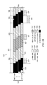
- FIG. 8 is a schematic diagram illustrating a DC balancing approach 800 for LC display panels.
- the system embodiments herein generally provide for the displaying of alternate left and right eye images. This may cause a problem with the dc balancing of the liquid crystal drive scheme.
- Conventional LC addressing alternate between frames the polarity of the applied LC addressing voltage to perform the dc balancing. If a single polarity were used, the electric field across the LC may cause ion migration and alteration of its electro-optic characteristics. The result would be the characteristic ‘image sticking’ phenomenon where pervious frames become visible as a ghost.
- Alternating the polarity between frames does a good job of dc balancing as the correlation between successive frames of a 2D image sequence is high and the time average field across any liquid crystal pixel equates very closely to zero. This however is not the case for stereoscopic content where alternate and not successive frames are correlated.
- the addressing polarity for successive right or left eye images may be altered. In the above system embodiments (barring those described in FIGS. 5A & 5B ), this means that the polarity may be altered every other frame as shown in FIG. 8 .
- An exemplary embodiment is provided with reference to the sequence 800 , illustrating a simplified addressing grid for a LC modulating panel.
- a first frame showing left-eye content
- the polarity of the addressing drive scheme is positive.
- a second frame showing right-eye content
- the polarity of the addressing drive scheme remains positive.
- a third frame (frame #3)
- switching to left-eye content the polarity of the addressing drive scheme is altered to negative polarity.
- frame #4 showing right-eye content
- the polarity of the addressing drive scheme is remains negative polarity.
- the cycle continues, such as the following frame shows left-eye content with positive polarity addressing, and so on.
- This concept of dc balancing can be extended to stereoscopic flat panel displays including those that might display more than two image sequences or views. In any particular case, toggling the polarity of the drive voltage between successive view images may perform adequate dc balancing.
- FIG. 9 is a schematic diagram of an exemplary polarization control panel 900 for a stereoscopic display having a plurality of polarization control segments, illustrating how a segmented or scrolling PCP 920 may be prone to visible segment boundaries.
- boundaries 922 a , 922 b , and 922 c may be visible in the left-eye view as 932 a , 932 b , 932 c and right-eye view 934 a , 934 b , 934 c , as shown.
- Such systems employing scrolling PCPs are prone to visible segment boundaries, since in general, the LC at the boundaries does not switch with the rest of the PCP LC.
- FIGS. 10A-C are schematic diagrams showing a cross section of a polarization control panel 1000 for a stereoscopic display having a plurality of polarization control segments, illustrating the cross section at a boundary between polarization control segments.
- the structures shown in FIG. 10A-C is typical of an LC modulator with a continuous common electrode on one side and a patterned structure on the other.
- a polarization control panel (PCP) 1000 for a stereoscopic display is operable to selectively transform the state of polarization of modulated light from an image modulation panel.
- the PCP 1000 has a plurality of polarization control segments.
- the PCP 1000 includes a liquid crystal (LC) layer 1010 disposed on a first plane, a common electrode 1020 disposed on a first side of the LC layer 1010 , and parallel to the first plane, a first electrode 1030 disposed on a second side of the LC layer, on a second plane that is parallel to the first plane, and a second electrode 1040 disposed on the second side of the LC layer, on the second plane.
- the electrodes e.g., first electrode 1030 , second electrode 1040 , third electrode (not shown), et cetera, may each form thick (about 1 cm) horizontal stripes.
- the electrodes 1030 and 1040 may include a transparent conductive oxide such as indium tin oxide (ITO).
- ITO indium tin oxide
- the gap 1050 between the electrodes 1030 , 1040 may be small, but lithography or equivalent methods of patterning the ITO electrodes may only attain modest gap widths (about 20 um) over such large area substrates. The effect of this gap is to allow unswitched LC lines to exist which may be clearly visible.
- the scrolling driving sequence of FIGS. 10A-C illustrate the ‘dead’ region from gap 1050 .
- the gap LC 1050 polarizes the light in an uncontrolled manner allowing each eye to see continuous leakage. If the gap 1050 between the drive electrodes 1030 , 1040 is small, their visibility is reduced, but to remove them altogether, the LC may be driven with the surrounding segments in such a manner as to avoid shorting the electrodes.
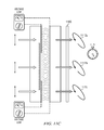
- FIGS. 11A-C are schematic diagrams showing a cross section of an improved segmented polarization control panel 1100 for a stereoscopic display having a plurality of polarization control segments, illustrating the cross section at a boundary between polarization control segments.
- FIG. 11A A solution to the shortcomings of the embodiment described in FIG. 10A-C is shown in FIG. 11A where buried electrode 1170 covering the gap region 1150 are capacitively coupled to one or both adjacent addressing electrodes.
- a polarization control panel (PCP) for a stereoscopic display 1100 is operable to transform the state of polarization of modulated light 1105 from an image modulation panel (not shown), the PCP having a plurality of polarization control segments 1130 , 1140 .
- PCP polarization control panel
- the PCP 1100 may include a liquid crystal (LC) layer 1110 , a common electrode layer 1120 disposed on a first side of the LC layer 1110 , a first electrode 1130 disposed on a second side of the LC layer 1110 , a second electrode 1140 disposed on the second side of the LC layer 1110 , and an intermediate electrode 1170 disposed on the second side of the LC layer 1110 and overlapping a portion of the first electrode 1130 and the second electrode 1140 .
- the PCP may further include a quarter wave plate 1160 in an output optical path.
- the LC layer 1110 may include zero twist nematic liquid crystal material having zero retardation in a first state and a half wave of retardation in a second state.
- the LC layer 1110 may be disposed on a first plane, wherein the common electrode 1120 is parallel to the first plane, wherein the first and second electrodes 1130 , 1140 are on a second plane that is parallel to the first plane, and where an intermediate electrode 1170 is on a third plane that is parallel to the first plane.
- a portion 1180 of the second electrode 1140 may overlap and be conductively isolated from the intermediate electrode 1170 .
- the first electrode 1130 and the intermediate electrode 1170 may be electrically coupled such that a portion 1180 of the intermediate electrode 1170 overlaps the second electrode 1140 .
- the first electrode 1130 and the common electrode 1120 may be selectively driven with a voltage high (corresponding to the first state) or a voltage low voltage potential (corresponding to the second state).
- the LC layer 1110 allows light 1105 a to pass through with zero retardation.
- the quarter wave plate 1160 in the output optical path operates to convert the linearly polarized light 1106 a to clockwise circularly-polarized light 1107 a .
- the LC layer 1110 transforms light 1105 a by a half wavelength at a particular design wavelength (e.g., the middle of the visible spectrum at 545 nm).
- the second electrode 1140 may be selectively driven with a voltage high or a voltage low voltage potential. As shown in FIG. 11A , similar to the above description, the second electrode is driven with a voltage high potential to output clockwise circularly-polarized light 1107 c . Since both the first and second electrodes 1130 , 1140 are being driven at a voltage high potential, intermediate electrode 1170 (which may be directly connected to first electrode 1130 in an embodiment, or capacitively coupled to the first electrode 1130 in another embodiment, or capacitively coupled to both the first and second electrodes, 1130 , 1140 in another embodiment) also is at the voltage high potential with respect to the common electrode 1120 . Accordingly, the liquid crystal material in the gap 1150 is operable to allow light 1106 b to pass without retardation in the voltage high state, such that output light following the quarter wave plate 1160 is also clockwise circularly-polarized light 1107 b.
- the lower polarization control segment and quarter wave plate collectively operates to output clockwise circularly-polarized light 1107 c , consistent with the description above.
- the upper polarization control segment and quarter wave plate 1160 collectively operate to output counter-clockwise circularly-polarized light 1117 a , when a voltage low potential is applied across first electrode 1130 and common electrode 1120 . Since the first and second electrodes 1130 , 1140 are driven differently, the intermediate electrode 1170 takes on a substantially intermediate voltage while preventing the flow of dc current which would cause undesirable heating and energy loss.
- the intermediate electrode 1170 follows suit and drives the gap LC 1150 into a similar modulating state.
- the intermediate electrode follows an average of drive electrode voltages between the first and second electrodes 1130 , 1140 , and drives the gap LC 1150 into a similar polarization control state. Accordingly, output light following the quarter wave plate 1160 is also counter-clockwise circularly-polarized light 1117 a , 1117 b , 1117 c.
- the disclosed technique of ‘hiding’ gaps between patterned ITO electrodes can be extended to any PCP element used in any direct or projected imaging system for 3D or other purposes. As such, it is not limited to the disclosed combination of a zero-twist nematic LC panel with a quarter-wave plate. Using the same principles, the disclosed technique may be applied to push-pull LC cell polarization modulators (e.g., pi-cells).
- push-pull LC cell polarization modulators e.g., pi-cells.
- such other PCP techniques are disclosed as taught in commonly-owned U.S. Pat. No. 6,975,345 to Lipton et al., or other polarization modulators, such as U.S. Pat. No. 7,528,906 to Mike Robinson, herein incorporated by reference.
- scrolling, addressing, updating, transitioning, changing, etc. directions are described herein as from top to bottom, but it should be appreciated that this is a non-limiting description, and that these directions may be from bottom to top (or even left to right or right to left). Further the scrolling, addressing, updating, transitioning, changing, etc. may be performed in groups of segments, lines, portions, areas, etc., such that several groups of can be addressed at once. The principles taught herein may be applied to such grouping of multi-segmented driving.
Abstract
Description
Claims (21)
Priority Applications (1)
| Application Number | Priority Date | Filing Date | Title |
|---|---|---|---|
| US12/853,273 US8525942B2 (en) | 2009-08-07 | 2010-08-09 | Segmented polarization control panel |
Applications Claiming Priority (2)
| Application Number | Priority Date | Filing Date | Title |
|---|---|---|---|
| US23234609P | 2009-08-07 | 2009-08-07 | |
| US12/853,273 US8525942B2 (en) | 2009-08-07 | 2010-08-09 | Segmented polarization control panel |
Publications (2)
| Publication Number | Publication Date |
|---|---|
| US20110032441A1 US20110032441A1 (en) | 2011-02-10 |
| US8525942B2 true US8525942B2 (en) | 2013-09-03 |
Family
ID=43534529
Family Applications (4)
| Application Number | Title | Priority Date | Filing Date |
|---|---|---|---|
| US12/853,265 Expired - Fee Related US8848045B2 (en) | 2009-08-07 | 2010-08-09 | Stereoscopic flat panel display with a continuously lit backlight |
| US12/853,273 Active 2031-05-03 US8525942B2 (en) | 2009-08-07 | 2010-08-09 | Segmented polarization control panel |
| US12/853,279 Expired - Fee Related US9122101B2 (en) | 2009-08-07 | 2010-08-09 | Stereoscopic flat panel display with scrolling backlight and synchronized liquid crystal display update |
| US12/853,274 Active 2031-10-09 US9285635B2 (en) | 2009-08-07 | 2010-08-09 | Stereoscopic flat panel display with updated blanking intervals |
Family Applications Before (1)
| Application Number | Title | Priority Date | Filing Date |
|---|---|---|---|
| US12/853,265 Expired - Fee Related US8848045B2 (en) | 2009-08-07 | 2010-08-09 | Stereoscopic flat panel display with a continuously lit backlight |
Family Applications After (2)
| Application Number | Title | Priority Date | Filing Date |
|---|---|---|---|
| US12/853,279 Expired - Fee Related US9122101B2 (en) | 2009-08-07 | 2010-08-09 | Stereoscopic flat panel display with scrolling backlight and synchronized liquid crystal display update |
| US12/853,274 Active 2031-10-09 US9285635B2 (en) | 2009-08-07 | 2010-08-09 | Stereoscopic flat panel display with updated blanking intervals |
Country Status (6)
| Country | Link |
|---|---|
| US (4) | US8848045B2 (en) |
| EP (3) | EP2462484A4 (en) |
| JP (2) | JP5943283B2 (en) |
| KR (2) | KR20120043766A (en) |
| CN (2) | CN102713738B (en) |
| WO (2) | WO2011017713A2 (en) |
Cited By (4)
| Publication number | Priority date | Publication date | Assignee | Title |
|---|---|---|---|---|
| US20110159929A1 (en) * | 2009-12-31 | 2011-06-30 | Broadcom Corporation | Multiple remote controllers that each simultaneously controls a different visual presentation of a 2d/3d display |
| US20110157172A1 (en) * | 2009-12-31 | 2011-06-30 | Broadcom Corporation | User controlled regional display of mixed two and three dimensional content |
| US8823782B2 (en) | 2009-12-31 | 2014-09-02 | Broadcom Corporation | Remote control with integrated position, viewer identification and optical and audio test |
| US9247286B2 (en) | 2009-12-31 | 2016-01-26 | Broadcom Corporation | Frame formatting supporting mixed two and three dimensional video data communication |
Families Citing this family (32)
| Publication number | Priority date | Publication date | Assignee | Title |
|---|---|---|---|---|
| US9088792B2 (en) * | 2007-06-08 | 2015-07-21 | Reald Inc. | Stereoscopic flat panel display with synchronized backlight, polarization control panel, and liquid crystal display |
| JP4511611B2 (en) | 2008-05-29 | 2010-07-28 | 株式会社エヌ・ティ・ティ・ドコモ | Radio resource selection method, radio base station, and mobile station |
| CN102713738B (en) | 2009-08-07 | 2016-01-27 | 瑞尔D股份有限公司 | There is the stereoscopic flat panel display of continuous illumination backlight |
| KR101310383B1 (en) | 2009-11-13 | 2013-09-23 | 엘지디스플레이 주식회사 | Stereoscopic Image Display Device |
| KR20110125416A (en) * | 2010-05-13 | 2011-11-21 | 삼성전자주식회사 | Three dimensional image display apparatus and driving method thereof |
| US20110298999A1 (en) * | 2010-06-08 | 2011-12-08 | Reald Inc. | Stereoscopic liquid crystal display systems |
| EP2593829B1 (en) | 2010-07-13 | 2021-09-22 | RealD Inc. | Field-of-view compensated polarization switch for short-throw 3d projection |
| CN102338936B (en) * | 2010-07-22 | 2014-12-10 | 群康科技(深圳)有限公司 | Displayer and electronic apparatus |
| US20120256905A1 (en) * | 2010-09-28 | 2012-10-11 | Reald Inc. | Segmented polarization modulators for stereoscopic projection |
| US9094678B1 (en) | 2010-09-29 | 2015-07-28 | Nvidia Corporation | System, method, and computer program product for inverting a polarity of each cell of a display device |
| US9094676B1 (en) | 2010-09-29 | 2015-07-28 | Nvidia Corporation | System, method, and computer program product for applying a setting based on a determined phase of a frame |
| KR20120035825A (en) * | 2010-10-06 | 2012-04-16 | 삼성전자주식회사 | 3d display panel, 3d display apparatus for using it, and driving methods thereof |
| KR101761884B1 (en) * | 2010-11-17 | 2017-08-07 | 삼성디스플레이 주식회사 | Display apparatus and method of driving the same |
| US20120212815A1 (en) * | 2011-01-25 | 2012-08-23 | Lg Chem, Ltd. | Stereoscopic image display device |
| US9224320B2 (en) | 2011-03-09 | 2015-12-29 | Dolby Laboratories Licensing Corporation | Projection display providing additional modulation and related methods |
| US20120235991A1 (en) * | 2011-03-15 | 2012-09-20 | Industrial Technology Research Institute | Three dimensional display and driving method thereof |
| WO2012125881A2 (en) * | 2011-03-15 | 2012-09-20 | Reald Inc. | Liquid crystal devices having reduced electrode-gap visibility |
| US9137522B2 (en) * | 2011-07-11 | 2015-09-15 | Realtek Semiconductor Corp. | Device and method for 3-D display control |
| KR20130020456A (en) * | 2011-08-19 | 2013-02-27 | 삼성디스플레이 주식회사 | 3d image display apparatus and method of driving the same |
| KR20130066902A (en) * | 2011-12-13 | 2013-06-21 | 삼성디스플레이 주식회사 | Method of displaying three-dimensional stereoscopic image and an display apparatus for performing the same |
| RU2488150C1 (en) * | 2011-12-30 | 2013-07-20 | Василий Александрович ЕЖОВ | Multi-standard liquid crystal stereoscopic glasses |
| KR101964892B1 (en) * | 2012-03-21 | 2019-04-05 | 삼성디스플레이 주식회사 | Method for displaying three-dimensional image and display apparatus for performing the same |
| US9164288B2 (en) * | 2012-04-11 | 2015-10-20 | Nvidia Corporation | System, method, and computer program product for presenting stereoscopic display content for viewing with passive stereoscopic glasses |
| US9030613B2 (en) * | 2012-05-04 | 2015-05-12 | Shenzhen China Star Optoelectronics Technology Co., Ltd. | Liquid crystal display panel and liquid crystal display apparatus and 3D image system |
| JP6458950B2 (en) * | 2012-05-18 | 2019-01-30 | リアルディー スパーク エルエルシー | Directional display device |
| US8952868B2 (en) | 2012-05-30 | 2015-02-10 | Reald Inc. | Method, apparatus and system on a chip for controlling a stereoscopic display device |
| CN103176308B (en) * | 2013-04-03 | 2015-10-14 | 上海交通大学 | Based on full resolution free stereo display equipment and the method for liquid crystal prism array |
| US10241341B2 (en) * | 2013-05-09 | 2019-03-26 | Sharp Kabushiki Kaisha | Stereoscopic display device |
| US10082675B2 (en) | 2014-10-21 | 2018-09-25 | Reald Inc. | High power handling polarization switches |
| KR20230071196A (en) | 2014-10-21 | 2023-05-23 | 리얼디 인크. | High power handling polarization switches |
| US10810773B2 (en) * | 2017-06-14 | 2020-10-20 | Dell Products, L.P. | Headset display control based upon a user's pupil state |
| US11300806B2 (en) * | 2018-11-08 | 2022-04-12 | Brass Roots Technologies, LLC | Multi-image projection method utilizing bit segment rate switching |
Citations (25)
| Publication number | Priority date | Publication date | Assignee | Title |
|---|---|---|---|---|
| US4281341A (en) | 1978-11-09 | 1981-07-28 | The Marconi Company Limited | Stereoscopic television system |
| US5991074A (en) | 1997-01-31 | 1999-11-23 | Canon Kabushiki Kaisha | Stereoscopic image display apparatus |
| JP2001154640A (en) | 1999-11-29 | 2001-06-08 | Idemitsu Kosan Co Ltd | Stereoscopic display device and stereoscopic display method |
| JP2002101427A (en) | 2000-09-22 | 2002-04-05 | Denso Corp | Stereoscopic image display device and method for controlling the same |
| US20020075202A1 (en) | 1994-10-25 | 2002-06-20 | Fergason James L. | Optical display system and method with optical shifting of pixel position including conversion of pixel layout to form delta to stripe pattern by time base multiplexing |
| US6774977B1 (en) | 1999-09-28 | 2004-08-10 | Sharp Laboratories Of Europe Limited | Liquid crystal device and display |
| US6975345B1 (en) | 1998-03-27 | 2005-12-13 | Stereographics Corporation | Polarizing modulator for an electronic stereoscopic display |
| US20060098285A1 (en) * | 2003-02-05 | 2006-05-11 | Ocuity Limited | Switchable display apparatus |
| US20060203338A1 (en) | 2005-03-12 | 2006-09-14 | Polaris Sensor Technologies, Inc. | System and method for dual stacked panel display |
| US20070008406A1 (en) | 2005-07-08 | 2007-01-11 | Samsung Electronics Co., Ltd. | High resolution 2D-3D switchable autostereoscopic display apparatus |
| KR100677637B1 (en) | 2006-02-22 | 2007-02-02 | 삼성전자주식회사 | High resolution autostereoscopic display |
| US20070035672A1 (en) | 2005-08-04 | 2007-02-15 | Samsung Electronics Co., Ltd. | High-resolution autostereoscopic display |
| US20070126691A1 (en) | 2005-12-01 | 2007-06-07 | Chi Mei Optoelectronics Corp. | Display Panel Having Multiple Display Regions and Corresponding Backlight Regions and Method of Controlling the Same |
| KR20080024901A (en) | 2006-09-15 | 2008-03-19 | 삼성전자주식회사 | Multiview autosterescopic display apparatus with lnterlaced image |
| US20080136762A1 (en) | 1994-10-25 | 2008-06-12 | Fergason James L | Optical display system and method, active and passive dithering using birefringence, color image superpositioning and display enhancement with phase coordinated polarization switching |
| US20080211736A1 (en) | 2003-02-06 | 2008-09-04 | Kazuki Taira | Three-dimensional image display apparatus |
| US20080218459A1 (en) * | 2007-03-09 | 2008-09-11 | Samsung Sdi Co., Ltd. | Electronic display device |
| US20080266388A1 (en) | 2003-02-05 | 2008-10-30 | Graham John Woodgate | Switchable Lens |
| US20080316303A1 (en) | 2007-06-08 | 2008-12-25 | Joseph Chiu | Display Device |
| KR20090018528A (en) | 2007-08-17 | 2009-02-20 | 삼성전자주식회사 | Apparatus of 2d/3d convertible display and driving method thereof |
| US20090102990A1 (en) * | 2005-05-21 | 2009-04-23 | Sharp Kabushiki Kaisha | Display |
| US7528906B2 (en) | 2006-01-23 | 2009-05-05 | Real D | Achromatic polarization switches |
| US20090153754A1 (en) * | 2007-12-18 | 2009-06-18 | Jung Sung Min | Electrically-driven liquid crystal lens and stereoscopic display device using the same |
| US20090224646A1 (en) * | 2008-03-07 | 2009-09-10 | Beom-Shik Kim | Electronic display device |
| KR20100023613A (en) | 2008-08-22 | 2010-03-04 | 삼성전자주식회사 | Display device and method of driving the same |
Family Cites Families (22)
| Publication number | Priority date | Publication date | Assignee | Title |
|---|---|---|---|---|
| JPH07301779A (en) * | 1994-04-28 | 1995-11-14 | Canon Inc | Picture projection device and method |
| JPH0815641A (en) * | 1994-06-27 | 1996-01-19 | Canon Inc | Display device |
| JP3492670B2 (en) * | 2001-03-30 | 2004-02-03 | 松下電器産業株式会社 | Display device, portable telephone and portable terminal device |
| JP3732775B2 (en) * | 2001-11-08 | 2006-01-11 | 株式会社東芝 | Liquid crystal display device and driving method of liquid crystal display device |
| JP2003202519A (en) * | 2001-12-28 | 2003-07-18 | Canon Inc | Stereoscopic image display device |
| AU2003214630A1 (en) * | 2002-04-15 | 2003-10-27 | Yitzhak Weissman | Stereoscopic display apparatus particularly useful with lcd projectors |
| JP2005077437A (en) * | 2003-08-29 | 2005-03-24 | Olympus Corp | Video display device, stereoscopic video display device, and on-vehicle video display device |
| JP4530632B2 (en) * | 2003-09-19 | 2010-08-25 | 富士通株式会社 | Liquid crystal display |
| US7221332B2 (en) * | 2003-12-19 | 2007-05-22 | Eastman Kodak Company | 3D stereo OLED display |
| JP2006017977A (en) * | 2004-07-01 | 2006-01-19 | Hitachi Displays Ltd | Image display apparatus |
| US7215356B2 (en) | 2004-10-05 | 2007-05-08 | Wintek Corporation | 3D stereo display method and a device thereof |
| JP2007072217A (en) * | 2005-09-07 | 2007-03-22 | Hunet Inc | Stereoscopic image display apparatus |
| KR100728113B1 (en) * | 2005-10-20 | 2007-06-13 | 삼성에스디아이 주식회사 | Stereoscopic display device and driving method thereof |
| JP4889332B2 (en) * | 2006-03-23 | 2012-03-07 | オリンパス株式会社 | Video display device |
| KR101244910B1 (en) * | 2006-04-03 | 2013-03-18 | 삼성전자주식회사 | Time sharing type autostereoscopic display apparatus and method for driving the same |
| KR101416227B1 (en) * | 2007-06-26 | 2014-07-07 | 삼성전자주식회사 | Driving method of liquid crystal polarization switch |
| US20080239485A1 (en) * | 2007-03-30 | 2008-10-02 | Arisawa Mfg. Co., Ltd. | Method for manufacturing stereoscopic displaying apparatus, method for manufacturing phase shift plate, and the phase shift plate thereby |
| JP2008287180A (en) | 2007-05-21 | 2008-11-27 | Toshiba Matsushita Display Technology Co Ltd | Liquid crystal display device |
| KR101406795B1 (en) | 2007-05-30 | 2014-06-12 | 삼성전자주식회사 | Apparatus and control for 2D/3D display with full resolution using scannable backlight |
| KR101362771B1 (en) * | 2008-09-17 | 2014-02-14 | 삼성전자주식회사 | Apparatus and method for displaying stereoscopic image |
| TWI392895B (en) | 2008-10-09 | 2013-04-11 | Au Optronics Corp | Switchable two and three dimensional display |
| CN102713738B (en) | 2009-08-07 | 2016-01-27 | 瑞尔D股份有限公司 | There is the stereoscopic flat panel display of continuous illumination backlight |
-
2010
- 2010-08-09 CN CN201080043690.9A patent/CN102713738B/en not_active Expired - Fee Related
- 2010-08-09 US US12/853,265 patent/US8848045B2/en not_active Expired - Fee Related
- 2010-08-09 EP EP10807300.8A patent/EP2462484A4/en not_active Withdrawn
- 2010-08-09 US US12/853,273 patent/US8525942B2/en active Active
- 2010-08-09 KR KR1020127006114A patent/KR20120043766A/en not_active Application Discontinuation
- 2010-08-09 EP EP12194887.1A patent/EP2573615A3/en not_active Withdrawn
- 2010-08-09 JP JP2012523998A patent/JP5943283B2/en not_active Expired - Fee Related
- 2010-08-09 CN CN201080043693.2A patent/CN102549483B/en not_active Expired - Fee Related
- 2010-08-09 KR KR1020127006108A patent/KR20120088664A/en not_active Application Discontinuation
- 2010-08-09 EP EP10807299.2A patent/EP2462483A4/en not_active Withdrawn
- 2010-08-09 US US12/853,279 patent/US9122101B2/en not_active Expired - Fee Related
- 2010-08-09 WO PCT/US2010/044933 patent/WO2011017713A2/en active Application Filing
- 2010-08-09 JP JP2012523999A patent/JP2013501950A/en not_active Withdrawn
- 2010-08-09 US US12/853,274 patent/US9285635B2/en active Active
- 2010-08-09 WO PCT/US2010/044934 patent/WO2011017714A2/en active Application Filing
Patent Citations (26)
| Publication number | Priority date | Publication date | Assignee | Title |
|---|---|---|---|---|
| US4281341A (en) | 1978-11-09 | 1981-07-28 | The Marconi Company Limited | Stereoscopic television system |
| US20080136762A1 (en) | 1994-10-25 | 2008-06-12 | Fergason James L | Optical display system and method, active and passive dithering using birefringence, color image superpositioning and display enhancement with phase coordinated polarization switching |
| US20020075202A1 (en) | 1994-10-25 | 2002-06-20 | Fergason James L. | Optical display system and method with optical shifting of pixel position including conversion of pixel layout to form delta to stripe pattern by time base multiplexing |
| US5991074A (en) | 1997-01-31 | 1999-11-23 | Canon Kabushiki Kaisha | Stereoscopic image display apparatus |
| US6975345B1 (en) | 1998-03-27 | 2005-12-13 | Stereographics Corporation | Polarizing modulator for an electronic stereoscopic display |
| US6774977B1 (en) | 1999-09-28 | 2004-08-10 | Sharp Laboratories Of Europe Limited | Liquid crystal device and display |
| JP2001154640A (en) | 1999-11-29 | 2001-06-08 | Idemitsu Kosan Co Ltd | Stereoscopic display device and stereoscopic display method |
| JP2002101427A (en) | 2000-09-22 | 2002-04-05 | Denso Corp | Stereoscopic image display device and method for controlling the same |
| US20080266388A1 (en) | 2003-02-05 | 2008-10-30 | Graham John Woodgate | Switchable Lens |
| US20060098285A1 (en) * | 2003-02-05 | 2006-05-11 | Ocuity Limited | Switchable display apparatus |
| US20080211736A1 (en) | 2003-02-06 | 2008-09-04 | Kazuki Taira | Three-dimensional image display apparatus |
| US20060203338A1 (en) | 2005-03-12 | 2006-09-14 | Polaris Sensor Technologies, Inc. | System and method for dual stacked panel display |
| US20090102990A1 (en) * | 2005-05-21 | 2009-04-23 | Sharp Kabushiki Kaisha | Display |
| KR20070006553A (en) | 2005-07-08 | 2007-01-11 | 삼성전자주식회사 | High resolution 2d-3d switchable autostereoscopic display apparatus |
| US20070008406A1 (en) | 2005-07-08 | 2007-01-11 | Samsung Electronics Co., Ltd. | High resolution 2D-3D switchable autostereoscopic display apparatus |
| US20070035672A1 (en) | 2005-08-04 | 2007-02-15 | Samsung Electronics Co., Ltd. | High-resolution autostereoscopic display |
| US20070126691A1 (en) | 2005-12-01 | 2007-06-07 | Chi Mei Optoelectronics Corp. | Display Panel Having Multiple Display Regions and Corresponding Backlight Regions and Method of Controlling the Same |
| US7528906B2 (en) | 2006-01-23 | 2009-05-05 | Real D | Achromatic polarization switches |
| KR100677637B1 (en) | 2006-02-22 | 2007-02-02 | 삼성전자주식회사 | High resolution autostereoscopic display |
| KR20080024901A (en) | 2006-09-15 | 2008-03-19 | 삼성전자주식회사 | Multiview autosterescopic display apparatus with lnterlaced image |
| US20080218459A1 (en) * | 2007-03-09 | 2008-09-11 | Samsung Sdi Co., Ltd. | Electronic display device |
| US20080316303A1 (en) | 2007-06-08 | 2008-12-25 | Joseph Chiu | Display Device |
| KR20090018528A (en) | 2007-08-17 | 2009-02-20 | 삼성전자주식회사 | Apparatus of 2d/3d convertible display and driving method thereof |
| US20090153754A1 (en) * | 2007-12-18 | 2009-06-18 | Jung Sung Min | Electrically-driven liquid crystal lens and stereoscopic display device using the same |
| US20090224646A1 (en) * | 2008-03-07 | 2009-09-10 | Beom-Shik Kim | Electronic display device |
| KR20100023613A (en) | 2008-08-22 | 2010-03-04 | 삼성전자주식회사 | Display device and method of driving the same |
Non-Patent Citations (9)
| Title |
|---|
| Denso Corp., Stereoscopic Image Display Device and Method for Controlling the Same, Machine Translation of JP 2002-101427 A from Patent Abstracts of Japan website, pp. 1-26. * |
| International Preliminary Report on Patentability of PCT/US10/044933 dated Feb. 7, 2012. |
| International Search Report and written opinion of international searching authority in co-pending PCT/US10/44934 dated Feb. 25, 2011. |
| International Search Report and Written Opinion of PCT/US10/044933 dated Feb. 25, 2011. |
| Kikuchi et al., "Optically Isotropic Nano-structured Liquid Crystal Composites for Display Applications," Digest of Technical Papers-Society for Information Display International Symposium, 40 (Bk. 2), pp. 578 (2009). |
| Kikuchi et al., "Optically Isotropic Nano-structured Liquid Crystal Composites for Display Applications," Digest of Technical Papers—Society for Information Display International Symposium, 40 (Bk. 2), pp. 578 (2009). |
| Lin et al., "Surface Polarity Controlled Horizontal Chevron Defect Free Surface Stabilized Ferroelectric Liquid Crystal Devices," pp. 1003, SID 09 Digest (2009). |
| PCT Notification of Transmittal of International Preliminary Report on Patentability patent application No. PCT/US10/44934 dated Apr. 9, 2012 and the International Preliminary Report on Patentability patent application No. PCT/US10/44934 dated Mar. 7, 2012. |
| Suzuki et al., "Crosstalk-Free 3D Display with Time-Sequential OCB LCD," pp. 428, SID 09 Digest (2009). |
Cited By (17)
| Publication number | Priority date | Publication date | Assignee | Title |
|---|---|---|---|---|
| US20110159929A1 (en) * | 2009-12-31 | 2011-06-30 | Broadcom Corporation | Multiple remote controllers that each simultaneously controls a different visual presentation of a 2d/3d display |
| US20110157172A1 (en) * | 2009-12-31 | 2011-06-30 | Broadcom Corporation | User controlled regional display of mixed two and three dimensional content |
| US20110157167A1 (en) * | 2009-12-31 | 2011-06-30 | Broadcom Corporation | Coordinated driving of adaptable light manipulator, backlighting and pixel array in support of adaptable 2d and 3d displays |
| US8823782B2 (en) | 2009-12-31 | 2014-09-02 | Broadcom Corporation | Remote control with integrated position, viewer identification and optical and audio test |
| US8854531B2 (en) | 2009-12-31 | 2014-10-07 | Broadcom Corporation | Multiple remote controllers that each simultaneously controls a different visual presentation of a 2D/3D display |
| US8922545B2 (en) | 2009-12-31 | 2014-12-30 | Broadcom Corporation | Three-dimensional display system with adaptation based on viewing reference of viewer(s) |
| US8964013B2 (en) | 2009-12-31 | 2015-02-24 | Broadcom Corporation | Display with elastic light manipulator |
| US8988506B2 (en) | 2009-12-31 | 2015-03-24 | Broadcom Corporation | Transcoder supporting selective delivery of 2D, stereoscopic 3D, and multi-view 3D content from source video |
| US9019263B2 (en) * | 2009-12-31 | 2015-04-28 | Broadcom Corporation | Coordinated driving of adaptable light manipulator, backlighting and pixel array in support of adaptable 2D and 3D displays |
| US9049440B2 (en) | 2009-12-31 | 2015-06-02 | Broadcom Corporation | Independent viewer tailoring of same media source content via a common 2D-3D display |
| US9066092B2 (en) | 2009-12-31 | 2015-06-23 | Broadcom Corporation | Communication infrastructure including simultaneous video pathways for multi-viewer support |
| US9124885B2 (en) | 2009-12-31 | 2015-09-01 | Broadcom Corporation | Operating system supporting mixed 2D, stereoscopic 3D and multi-view 3D displays |
| US9143770B2 (en) | 2009-12-31 | 2015-09-22 | Broadcom Corporation | Application programming interface supporting mixed two and three dimensional displays |
| US9204138B2 (en) * | 2009-12-31 | 2015-12-01 | Broadcom Corporation | User controlled regional display of mixed two and three dimensional content |
| US9247286B2 (en) | 2009-12-31 | 2016-01-26 | Broadcom Corporation | Frame formatting supporting mixed two and three dimensional video data communication |
| US9654767B2 (en) | 2009-12-31 | 2017-05-16 | Avago Technologies General Ip (Singapore) Pte. Ltd. | Programming architecture supporting mixed two and three dimensional displays |
| US9979954B2 (en) | 2009-12-31 | 2018-05-22 | Avago Technologies General Ip (Singapore) Pte. Ltd. | Eyewear with time shared viewing supporting delivery of differing content to multiple viewers |
Also Published As
| Publication number | Publication date |
|---|---|
| US9285635B2 (en) | 2016-03-15 |
| EP2573615A3 (en) | 2014-05-07 |
| EP2573615A2 (en) | 2013-03-27 |
| WO2011017713A3 (en) | 2011-04-28 |
| WO2011017714A4 (en) | 2011-07-14 |
| CN102713738B (en) | 2016-01-27 |
| EP2462484A2 (en) | 2012-06-13 |
| KR20120088664A (en) | 2012-08-08 |
| JP2013501950A (en) | 2013-01-17 |
| CN102713738A (en) | 2012-10-03 |
| WO2011017714A3 (en) | 2011-04-28 |
| EP2462483A2 (en) | 2012-06-13 |
| US8848045B2 (en) | 2014-09-30 |
| US9122101B2 (en) | 2015-09-01 |
| EP2462483A4 (en) | 2014-04-30 |
| WO2011017713A2 (en) | 2011-02-10 |
| US20110032441A1 (en) | 2011-02-10 |
| CN102549483A (en) | 2012-07-04 |
| EP2462484A4 (en) | 2014-02-12 |
| US20110032439A1 (en) | 2011-02-10 |
| KR20120043766A (en) | 2012-05-04 |
| WO2011017714A2 (en) | 2011-02-10 |
| CN102549483B (en) | 2016-05-18 |
| US20110032345A1 (en) | 2011-02-10 |
| US20110032440A1 (en) | 2011-02-10 |
| JP5943283B2 (en) | 2016-07-05 |
| JP2013501949A (en) | 2013-01-17 |
Similar Documents
| Publication | Publication Date | Title |
|---|---|---|
| US8525942B2 (en) | Segmented polarization control panel | |
| JP5556492B2 (en) | Electro-optical device and stereoscopic display device | |
| US8766890B2 (en) | Crosstalk suppression in time sequential liquid crystal stereoscopic display systems | |
| US8970682B2 (en) | 3 dimensional image display device and method of driving the same | |
| JP5619863B2 (en) | Non-glasses stereoscopic image display apparatus and control method thereof | |
| KR101291805B1 (en) | Stereoscopic image display and driving method thereof | |
| WO2011033684A1 (en) | Image display device | |
| US8953106B2 (en) | Display unit, barrier device, and method of driving display unit | |
| JP2012027427A (en) | Stereoscopic display | |
| US8724041B2 (en) | Drive scheme for stereoscopic display polarization modulator and apparatus for same | |
| JP2006119206A (en) | Liquid crystal display | |
| US20120256905A1 (en) | Segmented polarization modulators for stereoscopic projection | |
| KR101941956B1 (en) | Stereoscopic image display and control method thereof | |
| KR20120081438A (en) | Apparatus and method for displaying stereo-scopic image on lcd | |
| KR20140048662A (en) | Stereoscopic image display and control method thereof |
Legal Events
| Date | Code | Title | Description |
|---|---|---|---|
| AS | Assignment |
Owner name: REALD INC., CALIFORNIA Free format text: ASSIGNMENT OF ASSIGNORS INTEREST;ASSIGNORS:ROBINSON, MICHAEL G.;CHEN, JIANMIN;REEL/FRAME:024861/0517 Effective date: 20100809 |
|
| AS | Assignment |
Owner name: CITY NATIONAL BANK, AS ADMINISTRATIVE AGENT, CALIF Free format text: PATENT SECURITY AGREEMENT;ASSIGNOR:REALD, INC.;REEL/FRAME:028146/0006 Effective date: 20120419 |
|
| STCF | Information on status: patent grant |
Free format text: PATENTED CASE |
|
| AS | Assignment |
Owner name: REALD INC., CALIFORNIA Free format text: RELEASE FROM PATENT SECURITY AGREEMENTS AT REEL/FRAME NO. 28146/0006;ASSIGNOR:CITY NATIONAL BANK;REEL/FRAME:038216/0436 Effective date: 20160322 |
|
| AS | Assignment |
Owner name: HIGHBRIDGE PRINCIPAL STRATEGIES, LLC, NEW YORK Free format text: SECURITY INTEREST;ASSIGNORS:REALD INC.;STEREOGRAPHICS CORPORATION;COLORLINK INC.;AND OTHERS;REEL/FRAME:038243/0526 Effective date: 20160322 |
|
| FPAY | Fee payment |
Year of fee payment: 4 |
|
| AS | Assignment |
Owner name: JEFFERIES FINANCE LLC, AS COLLATERAL AGENT, NEW YORK Free format text: SECURITY INTEREST;ASSIGNORS:REALD INC.;RHOMBUS INTERMEDIATE HOLDINGS, LP;REALD HOLDINGS, INC;AND OTHERS;REEL/FRAME:047723/0767 Effective date: 20181130 Owner name: JEFFERIES FINANCE LLC, AS COLLATERAL AGENT, NEW YO Free format text: SECURITY INTEREST;ASSIGNORS:REALD INC.;RHOMBUS INTERMEDIATE HOLDINGS, LP;REALD HOLDINGS, INC;AND OTHERS;REEL/FRAME:047723/0767 Effective date: 20181130 |
|
| AS | Assignment |
Owner name: JEFFERIES FINANCE LLC, AS COLLATERAL AGENT, NEW YORK Free format text: SECURITY INTEREST;ASSIGNORS:REALD INC.;RHOMBUS INTERMEDIATE HOLDINGS, LP;REALD HOLDINGS, INC;AND OTHERS;REEL/FRAME:047740/0085 Effective date: 20181130 Owner name: JEFFERIES FINANCE LLC, AS COLLATERAL AGENT, NEW YO Free format text: SECURITY INTEREST;ASSIGNORS:REALD INC.;RHOMBUS INTERMEDIATE HOLDINGS, LP;REALD HOLDINGS, INC;AND OTHERS;REEL/FRAME:047740/0085 Effective date: 20181130 Owner name: REALD INC., CALIFORNIA Free format text: RELEASE BY SECURED PARTY;ASSIGNOR:HPS INVESTMENT PARTNERS, LLC, AS COLLATERAL AGENT;REEL/FRAME:047741/0621 Effective date: 20181130 Owner name: REALD DDMG ACQUISITION, LLC, CALIFORNIA Free format text: RELEASE BY SECURED PARTY;ASSIGNOR:HPS INVESTMENT PARTNERS, LLC, AS COLLATERAL AGENT;REEL/FRAME:047741/0621 Effective date: 20181130 Owner name: COLORLINK, INC., CALIFORNIA Free format text: RELEASE BY SECURED PARTY;ASSIGNOR:HPS INVESTMENT PARTNERS, LLC, AS COLLATERAL AGENT;REEL/FRAME:047741/0621 Effective date: 20181130 Owner name: STEREOGRAPHICS CORPORATION, CALIFORNIA Free format text: RELEASE BY SECURED PARTY;ASSIGNOR:HPS INVESTMENT PARTNERS, LLC, AS COLLATERAL AGENT;REEL/FRAME:047741/0621 Effective date: 20181130 |
|
| AS | Assignment |
Owner name: HPS INVESTMENT PARTNERS, LLC, AS THE SUCCESSOR-IN-INTEREST, NEW YORK Free format text: SECURITY INTEREST;ASSIGNOR:JEFFERIES FINANCE LLC, AS COLLATERAL AGENT;REEL/FRAME:052622/0104 Effective date: 20200506 Owner name: CORTLAND CAPITAL MARKET SERVICES LLC, AS THE SUCCESSOR COLLATERAL AGENT, ILLINOIS Free format text: ASSIGNMENT OF SECURITY INTEREST IN COLLATERAL;ASSIGNOR:JEFFERIES FINANCE LLC, AS COLLATERAL AGENT;REEL/FRAME:052623/0086 Effective date: 20200506 |
|
| AS | Assignment |
Owner name: REALD INC., CALIFORNIA Free format text: RELEASE OF SECURITY INTEREST RECORDED AT REEL/FRAME 047740/0085;ASSIGNOR:CORTLAND CAPITAL MARKET SERVICES, LLC;REEL/FRAME:054593/0247 Effective date: 20201120 Owner name: REALD DDMG ACQUISITION, LLC, CALIFORNIA Free format text: RELEASE OF SECURITY INTEREST RECORDED AT REEL/FRAME 047740/0085;ASSIGNOR:CORTLAND CAPITAL MARKET SERVICES, LLC;REEL/FRAME:054593/0247 Effective date: 20201120 Owner name: COLORLINK, INC., CALIFORNIA Free format text: RELEASE OF SECURITY INTEREST RECORDED AT REEL/FRAME 047740/0085;ASSIGNOR:CORTLAND CAPITAL MARKET SERVICES, LLC;REEL/FRAME:054593/0247 Effective date: 20201120 Owner name: RHOMBUS INTERMEDIATE HOLDINGS, LP, CALIFORNIA Free format text: RELEASE OF SECURITY INTEREST RECORDED AT REEL/FRAME 047740/0085;ASSIGNOR:CORTLAND CAPITAL MARKET SERVICES, LLC;REEL/FRAME:054593/0247 Effective date: 20201120 Owner name: REALD SPARK, LLC, CALIFORNIA Free format text: RELEASE OF SECURITY INTEREST RECORDED AT REEL/FRAME 047740/0085;ASSIGNOR:CORTLAND CAPITAL MARKET SERVICES, LLC;REEL/FRAME:054593/0247 Effective date: 20201120 |
|
| MAFP | Maintenance fee payment |
Free format text: PAYMENT OF MAINTENANCE FEE, 8TH YEAR, LARGE ENTITY (ORIGINAL EVENT CODE: M1552); ENTITY STATUS OF PATENT OWNER: LARGE ENTITY Year of fee payment: 8 |