US8512830B2 - Filament-strung stand-off elements for maintaining pane separation in vacuum insulating glazing units - Google Patents
Filament-strung stand-off elements for maintaining pane separation in vacuum insulating glazing units Download PDFInfo
- Publication number
- US8512830B2 US8512830B2 US12/688,853 US68885310A US8512830B2 US 8512830 B2 US8512830 B2 US 8512830B2 US 68885310 A US68885310 A US 68885310A US 8512830 B2 US8512830 B2 US 8512830B2
- Authority
- US
- United States
- Prior art keywords
- stand
- elements
- filament
- panes
- vigu
- Prior art date
- Legal status (The legal status is an assumption and is not a legal conclusion. Google has not performed a legal analysis and makes no representation as to the accuracy of the status listed.)
- Expired - Fee Related, expires
Links
Images


Classifications
-
- E—FIXED CONSTRUCTIONS
- E06—DOORS, WINDOWS, SHUTTERS, OR ROLLER BLINDS IN GENERAL; LADDERS
- E06B—FIXED OR MOVABLE CLOSURES FOR OPENINGS IN BUILDINGS, VEHICLES, FENCES OR LIKE ENCLOSURES IN GENERAL, e.g. DOORS, WINDOWS, BLINDS, GATES
- E06B3/00—Window sashes, door leaves, or like elements for closing wall or like openings; Layout of fixed or moving closures, e.g. windows in wall or like openings; Features of rigidly-mounted outer frames relating to the mounting of wing frames
- E06B3/66—Units comprising two or more parallel glass or like panes permanently secured together
- E06B3/663—Elements for spacing panes
- E06B3/66309—Section members positioned at the edges of the glazing unit
- E06B3/66371—Section members positioned at the edges of the glazing unit positioned entirely outside the gap between the panes
-
- E—FIXED CONSTRUCTIONS
- E06—DOORS, WINDOWS, SHUTTERS, OR ROLLER BLINDS IN GENERAL; LADDERS
- E06B—FIXED OR MOVABLE CLOSURES FOR OPENINGS IN BUILDINGS, VEHICLES, FENCES OR LIKE ENCLOSURES IN GENERAL, e.g. DOORS, WINDOWS, BLINDS, GATES
- E06B3/00—Window sashes, door leaves, or like elements for closing wall or like openings; Layout of fixed or moving closures, e.g. windows in wall or like openings; Features of rigidly-mounted outer frames relating to the mounting of wing frames
- E06B3/66—Units comprising two or more parallel glass or like panes permanently secured together
- E06B3/6612—Evacuated glazing units
-
- E—FIXED CONSTRUCTIONS
- E06—DOORS, WINDOWS, SHUTTERS, OR ROLLER BLINDS IN GENERAL; LADDERS
- E06B—FIXED OR MOVABLE CLOSURES FOR OPENINGS IN BUILDINGS, VEHICLES, FENCES OR LIKE ENCLOSURES IN GENERAL, e.g. DOORS, WINDOWS, BLINDS, GATES
- E06B3/00—Window sashes, door leaves, or like elements for closing wall or like openings; Layout of fixed or moving closures, e.g. windows in wall or like openings; Features of rigidly-mounted outer frames relating to the mounting of wing frames
- E06B3/66—Units comprising two or more parallel glass or like panes permanently secured together
- E06B3/663—Elements for spacing panes
- E06B3/66304—Discrete spacing elements, e.g. for evacuated glazing units
-
- Y—GENERAL TAGGING OF NEW TECHNOLOGICAL DEVELOPMENTS; GENERAL TAGGING OF CROSS-SECTIONAL TECHNOLOGIES SPANNING OVER SEVERAL SECTIONS OF THE IPC; TECHNICAL SUBJECTS COVERED BY FORMER USPC CROSS-REFERENCE ART COLLECTIONS [XRACs] AND DIGESTS
- Y02—TECHNOLOGIES OR APPLICATIONS FOR MITIGATION OR ADAPTATION AGAINST CLIMATE CHANGE
- Y02A—TECHNOLOGIES FOR ADAPTATION TO CLIMATE CHANGE
- Y02A30/00—Adapting or protecting infrastructure or their operation
- Y02A30/24—Structural elements or technologies for improving thermal insulation
- Y02A30/249—Glazing, e.g. vacuum glazing
-
- Y—GENERAL TAGGING OF NEW TECHNOLOGICAL DEVELOPMENTS; GENERAL TAGGING OF CROSS-SECTIONAL TECHNOLOGIES SPANNING OVER SEVERAL SECTIONS OF THE IPC; TECHNICAL SUBJECTS COVERED BY FORMER USPC CROSS-REFERENCE ART COLLECTIONS [XRACs] AND DIGESTS
- Y02—TECHNOLOGIES OR APPLICATIONS FOR MITIGATION OR ADAPTATION AGAINST CLIMATE CHANGE
- Y02B—CLIMATE CHANGE MITIGATION TECHNOLOGIES RELATED TO BUILDINGS, e.g. HOUSING, HOUSE APPLIANCES OR RELATED END-USER APPLICATIONS
- Y02B80/00—Architectural or constructional elements improving the thermal performance of buildings
- Y02B80/22—Glazing, e.g. vaccum glazing
Definitions
- the following disclosure relates to insulating windows and glazing products. More particularly, it relates to vacuum insulating glazing units with multiple transparent panes having an evacuated space therebetween.
- VIGU Vacuum insulating glazing units
- VIGU assemblies comprising two spaced-apart transparent panes (typically formed of glass) having an evacuated atmosphere therebetween to reduce the thermal conductivity between the panes.
- Most VIGU assemblies further include a plurality of small objects that are positioned between the panes so as to touch the opposing inside surfaces of the panes. When the enclosed volume between the panes is evacuated of air, these objects maintain the separation between the panes against the forces applied by atmospheric pressure bearing on the external surfaces.
- separation-maintaining objects are called a variety of names in the prior art, e.g., pillars and spacers, however, in this application they will be referred to primarily as “stand-off elements” to differentiate them from other items that are in common use in the insulating glass (IG) industry.
- IG insulating glass
- each stand-off element is first individually positioned on one of the two panes and then affixed in place.
- This positioning of the stand-off elements may be done manually, by robotic “pick and place” machines or other automatic devices, by liquid transport or by screen printing/stenciling.
- the affixing of the stand-off elements to the pane may be done individually or en masse using, for example, adhesives, tack welding or heating in a furnace.
- the spacers are affixed to both panes of the VIGU. Regardless of the process used, the complexity of individually positioning and affixing stand-off elements is believed to be a significant component in the cost of manufacturing VIGU products. A reduction in manufacturing costs is needed to facilitate the widespread entry of VIGU products into the commercial and residential glazing market.
- the total surface area of stand-off elements required to prevent cracking of the panes or crushing of the stand-off elements themselves may be calculated.
- the question of whether to provide this required surface area by using a relatively small number of relatively large (i.e., in projected area) stand-off elements, or alternatively, by using a relatively large number of relatively small stand-off elements has posed a dilemma for manufacturers.
- a relatively small number of relatively large stand-off elements is easier (and thus less costly) to manufacture and affix on the pane, however, the larger size makes the stand-off elements more likely to be visible, making the VIGU less desirable from an aesthetic standpoint.
- VIGU stand-off elements that are easy to manufacture and affix on the pane, even when the stand-off elements are very small in size and very large in number.
- a stand-off assembly for a Vacuum Insulating Glazing Unit comprises a filament formed of a vacuum-resistant material that does not materially decompose or materially outgas over a prolonged period at a reduced pressure, and a plurality of stand-off elements affixed to the filament at predetermined positions.
- Each stand-off element is formed of a vacuum-resistant material that does not decompose or outgas over the prolonged period at the reduced pressure.
- a stand-off array unit for a VIGU comprises first and second anchors, a plurality of filaments, and a plurality of stand-off elements.
- the filaments and the stand-off elements are formed of vacuum-resistant material(s) that do not decompose or outgas over a prolonged period at a reduced pressure.
- the anchors are spaced apart from one another a distance that substantially corresponds to the distance between the opposite edges of one pane of the VIGU.
- Each filament is attached at one end to the first anchor and at the other end to the second anchor.
- the filaments are collectively disposed substantially parallel to one another.
- the stand-off elements are disposed on each filament at predetermined positions along the filament and have a height equal to the predetermined height of the gap between the panes of the VIGU.
- the stand-off elements may be formed separately from the filament and then affixed onto the filament, or, in another embodiment, they may be integrally formed from the material of the filament itself.
- a VIGU comprises first and second panes of transparent material, first and second anchors, a plurality of filaments, a plurality of stand-off elements, and seals.
- the first and second panes of transparent material have edges and inner and outer faces, are disposed with their inner faces substantially opposing one another, and are separated by a gap having a predetermined height.
- the first and second anchors are disposed at opposite edges of one pane of the VIGU.
- Each filament is attached at one end to the first anchor and at the other end to the second anchor, and the filaments are collectively disposed between the panes substantially parallel to one another.
- the stand-off elements are affixed to each filament at predetermined positions along the filament, and have a height equal to the predetermined minimum height of the gap.
- the seals are disposed about the edges of the panes, enclosing the stand-off elements within a volume between the panes from which the atmosphere may be evacuated to form a partial vacuum.
- FIG. 1A is a cross-sectional side view of a VIGU in accordance with the PRIOR ART
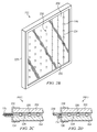
- FIG. 1B shows one pane of the PRIOR ART VIGU of FIG. 1A showing the discrete stand-off elements individually positioned thereon;
- FIGS. 2A-2B illustrate a VIGU in accordance with one aspect of the current disclosure, wherein FIG. 2A is a cross-sectional side view of a VIGU having filament-strung stand-offs, and FIG. 2B is a perspective view of a complete VIGU of FIG. 2A ;
- FIGS. 2C-2D illustrate alternative embodiments of VIGU in accordance with other aspect of the current disclosure, wherein FIG. 2C is a cross-sectional side view of a VIGU having a filament anchored between the seal members and wherein FIG. 2D is a cross-sectional side view of a VIGU having a filament anchored to the interior of the seal members
- FIGS. 3A-3C illustrate the attachment of deformable cylindrical stand-off elements to a filament in accordance with another aspect, wherein FIG. 3A shows the stand-off elements before fixation, FIG. 3B shows the stand-off elements after fixation on the filament and FIG. 3C shows an alternative stand-off element that is deformed to provide flat surfaces;
- FIGS. 4A and 4B illustrate the attachment of cylindrical stand-offs element to a filament using laser welding in accordance with another aspect, wherein FIG. 4A shows the stand-off elements before fixation and FIG. 4B shows the stand-off elements after fixation on the filament;
- FIGS. 5A-5D illustrate the attachment of split cylindrical stand-off elements to a filament in accordance with another aspect, wherein FIG. 5A shows the stand-off elements before placement on the filament, FIG. 5B shows the stand-off elements after placement but before fixation, FIG. 5C shows the stand-off elements after fixation on the filament and FIG. 5D shows an alternative stand-off element having a rectangular cross-section that provide flat surfaces.
- FIG. 6A shows a stand-off assembly having rectangular stand-off elements in accordance with another embodiment
- FIG. 6B shows a stand-off assembly having triangular, prism-shaped stand-off elements in accordance with another embodiment
- FIGS. 7A and 7B illustrate stand-off elements formed in-place on the filament in accordance with another aspect, wherein FIG. 7A shows the un-solidified material being deposited on the filament and FIG. 7B shows the stand-off elements after solidification on the filament;
- FIGS. 8A-8B illustrate stand-off assemblies having integral stand-off elements, wherein FIG. 8A shows a stand-off assembly having looped stand-offs, and FIG. 8B shows a stand-off assembly having variable dimension filaments;
- FIGS. 8C-8E are end views of alternative stand-off assemblies. Namely, FIG. 8C shows the stand-off assembly of FIG. 8B taken along line 8 C- 8 C of FIG. 8B , FIG. 8D is an alternative stand-off assembly having raised portions with octagonal cross-sections and FIG. 8E is another alternative stand-off assembly having raised portions with rectangular cross-sections;
- FIGS. 9A-9C illustrate the orientation of stand-off elements in a stand-off array unit on a pane of the VIGU, wherein FIG. 9A shows the stand-off elements before orientation, FIG. 9B shows a dithering signal being applied to the pane and FIG. 9C shows the stand-off elements after it moves into the desired orientation;
- FIG. 10 illustrates a stand-off array unit including multiple stand-off assemblies attached between anchor elements in accordance with another aspect
- FIG. 11 illustrates a stand-off array unit including multiple stand-off assemblies attached between anchor elements having a different stand-off pattern in accordance with another aspect
- FIG. 12 illustrates a stand-off array unit including multiple stand-off assemblies attached between anchor elements on filaments running in a crossing pattern in accordance with another aspect
- FIG. 13 illustrates another stand-off array unit including multiple stand-off assemblies attached between anchor elements on filaments running in a crossing pattern in accordance with another aspect.
- the VIGU 100 includes two panes 102 and 104 formed of a transparent material, typically glass.
- the panes 102 and 104 are disposed with their inner faces 106 and 108 , respectively, substantially opposing one another and separated by a gap 110 having a predetermined width.
- a plurality of individual stand-off elements 112 are disposed between panes 102 and 104 such that they are in with contact the inner faces 106 and 108 .
- Edge seals 114 are provided around the periphery of the panes 102 and 104 enclosing the stand-off elements 112 within a volume between the panes from which the atmosphere may be evacuated to form a partial vacuum.
- the stand-off elements 112 serve to maintain the separation of the panes 102 and 104 against the forces produced by atmospheric pressure bearing on the outside surface of the panes.
- each stand-off element 112 is disposed on the inner face 108 of the pane 104 and is not connected to any of the other stand-offs.
- stand-off elements may be affixed to one or both panes, but not to other stand-offs.
- the VIGU 200 comprises first and second panes 202 and 204 of transparent material, each pane having edges 206 and 208 , inner faces 210 and 212 and outer faces 214 and 216 , respectively.
- the panes 202 and 204 are made of glass, for example soda-lime glass, but in other embodiments they may be formed of other types of glass, plastic or other transparent materials.
- the panes 202 and 204 may be identical; however, this is not required.
- panes may have different dimensions, e.g., length, width and/or thickness, be made of different materials, or have different coatings or treatments.
- pane 202 has different edge-to-edge width than pane 204 .
- the panes 202 and 204 are disposed with inner faces 210 and 212 substantially opposing one another and separated by a gap 218 having a predetermined height H G .
- anchors 220 and 222 are disposed at opposite edges of at least one pane of the VIGU 200 .
- the anchors are preferably formed of a vacuum-resistant material that does not materially decompose or materially outgas over a prolonged period at a reduced pressure. Decomposition or outgassing is considered material if it adversely affects the structural strength, surface tribology, visibility, appearance, or vacuum level of the VIGU to the extent that such characteristic falls below the unit's minimum requirements.
- anchors 220 and 222 are formed from stainless steel, but in other embodiments, they may be formed of various metals, metal alloys or non-metal materials.
- a plurality of wires or filaments 224 are collectively disposed within the gap 218 between the panes 202 and 204 and substantially parallel to one another. Each filament is attached at one end to anchor 220 and at the other end to anchor 222 . In the illustrated embodiment, the filaments 224 are attached to the anchors 220 , 222 with welds 225 . However, in other embodiments, the filaments may be attached in other manners as further described herein.
- a plurality of stand-off elements 226 are formed on or affixed to each filament 224 at predetermined positions along the filament, thus creating a stand-off assembly.
- Each stand-off element 226 has a height H S that is substantially equal to the nominal H G (plus an allowance for dimensional variation of the glass panes, e.g., “roller wave distortion”) such that the inner faces 210 and 212 of the panes remain separated by the required amount.
- Seals 228 are disposed about the edges of the panes 202 and 204 , enclosing the stand-off elements 226 within a volume between the panes from which the atmosphere may be evacuated to form a partial vacuum.
- the anchors 220 and 222 , filaments 224 and stand-off elements 226 are all enclosed within the seals 228 .
- portions of the anchors, filaments and/or stand-off elements may lie outside the sealed volume.
- the anchors 220 and 222 may form an integral part of the seal itself.
- the seals 228 are bonded hermetically to the panes 202 and 204 such that a high vacuum may be maintained within the gap 218 for an extended period of time.
- the seals are sufficient to maintain a vacuum within the range of 10 ⁇ 6 torr to 10 ⁇ 3 torr for a minimum of twenty-five years.
- FIG. 2B there is illustrated a complete VIGU 200 showing the stand-off assemblies 230 , each comprising a plurality of stand-off elements 226 affixed to a filament 224 .
- the stand-off assemblies 230 are disposed in a parallel arrangement to one another in the gap 218 ( FIG. 2A ) between the panes 202 and 204 .
- the stand-off assemblies 230 will be disposed so as to be vertically oriented when the VIGU 200 is installed in a building. It will be appreciated that the size of the stand-off assemblies 230 are greatly exaggerated in FIG. 2B for purposes of illustration. In embodiments using the preferred dimensions of the filaments 224 and stand-off elements 226 , the stand-off assemblies 230 will be virtually invisible at normal viewing distances.
- the wires or filaments 224 used to position the many individual stand-off elements 226 between the inner and outer VIGU glass panes 202 and 204 have a diameter within the range from 0.0003 inches to 0.002 inches. In a preferred embodiment, the filaments 224 have a diameter of 0.001 inches or less.
- the filaments 224 may be wires formed from a variety of metals or metal alloys, including stainless steel, controlled expansion metal alloy, inconel, brass, bronze, copper and titanium; or they may be non-metal filaments formed of non-metal materials including but not limited to glass fibers, carbon fibers, ceramic-based materials and nano-technology structures such as fibers containing carbon nanotubes.
- controlled-expansion metal alloys refers to high-nickel alloys, nickel-iron alloys and other metal alloys having thermal expansion characteristics similar to any of the Permalloy brand(s) of alloy(s) available from ATI of Pittsburgh, Pa., or to any of Invar 36 brand, Low Expansion 39 brand, Low Expansion 42 brand, Thermostat 42 Alloy brand, Low Expansion 45 brand, Low Expansion 49 brand, Glass Sealing 52 brand, Alloy 42 brand, Alloy 49 brand or Kovar brand alloys available from Carpenter Technology Corporation (CARTECH) of Reading, Pa.
- the filaments 224 may be threads formed of natural or synthetic industrial fibers such as cotton, rayon, nylon, silk, aramid fibers (e.g., Kevlar®), etc. Such natural or synthetic industrial fibers may or may not be completely vacuum-resistant, but may nonetheless be suitable for use in some embodiments.
- the filaments 224 may have a single-stranded (i.e., monofilament) structure, multi-stranded structure, or spun structure.
- the filaments 224 are stainless steel wires. Regardless of what material is used for the supporting filaments 224 , the material must not outgas to the extent of materially degrading the vacuum of the device or its other characteristics.
- the supporting filaments 224 exhibit low visible light reflectivity, thereby reducing their visibility.
- This low light reflectivity of the supporting filament 224 may be an inherent characteristic of the underlying filament material, or it may result from a surface treatment or surface coating applied to the filament.
- a plurality of stand-off assemblies 230 are attached at their respective free ends to separate wire-positioning forms or anchors 220 , 222 , thereby creating a discrete stand-off array unit ( FIG. 10 ) for subsequent positioning between the transparent panes of the VIGU.
- the anchors 220 , 222 may be constructed of metal or other vacuum-resistant materials with long-term stability and zero or near-zero out-gassing properties when used inside the VIGU.
- the support filaments 224 may be fastened to the anchors 220 , 222 by welding, by soldering, by securing the filaments through holes in the anchors, or by deforming portions of the anchors to grip the ends of the filaments.
- the filaments are attached to the anchors using welding.
- the filament/wire-positioning anchors 220 , 222 may have any form that supports the ends of the filaments 224 and facilitates holding the stand-off elements 226 in position within the gap 218 between the transparent panes 202 , 204 of the VIGU.
- the anchors themselves may or may not be disposed completely outside the gap 218 , i.e., some portion of the anchors 220 , 222 may extend between the panes 202 , 204 . However, the anchors 220 , 222 will not typically be readily visible in the completed VIGU.
- the anchors 220 , 222 are formed in a shape that can be readily secured to the edges of the panes 202 , 204 and/or to the seals 228 to keep the stand-off array unit in place during further assembly of the VIGU, during shipping, and during the life of the VIGU in its final (i.e., end-use) installation.
- FIGS. 2C-2D there is illustrated alternative embodiments of VIGU in accordance with other aspect of the current disclosure.
- the separate seals 228 and filament anchors 220 of FIG. 2A are replaced by a pair of seal members.
- FIG. 2C shows a VIGU 200 C having a filament 224 anchored between the separately-formed seal members 232 and 234 .
- An end seal 235 e.g., a weld, hermetically bonds the two seal members 232 , 234 and the filament 224 at the same time.
- FIG. 2D shows a side view of a VIGU 200 D having a filament 224 anchored to the interior of one seal member 236 with a joint 237 .
- the joint 237 need not be hermetic, since it is inside the evacuated area formed by the seals, thus adhesives may be used in case the material of the filament 224 is incompatible with welding.
- the second seal member 238 does not connect to the filament 224 . Instead, the seal members 236 , 238 are hermetically sealed with a second seal 239 , e.g., a weld seal.
- the filament-strung stand-offs of the current invention mitigate the visual detection of the gap-maintaining components by using individual stand-off elements which are relatively small in dimension, projected surface area and height.
- the range of stand-off height which equates to the nominal gap between the VIGU panes plus some additional small amount (e.g., to compensate for dimensional variation), may be within the range from 0.003 inches to 0.012 inches; in preferred embodiments the height may be about 0.006 inches to about 0.009 inches.
- the projected shape (also called the “footprint”) of the stand-off elements is the shape that is apparent when viewing the stand-off elements in a direction normal to the largest surface area of the window pane.
- each stand-off footprint may be round (i.e., circular), but as further described below, it is not limited to round. Regardless of the actual shape of the stand-off footprint, in preferred embodiments each stand-off footprint will fit within a projected circle having a diameter within the range from 0.004 inches to 0.018 inches. In more preferred embodiments, the footprint of each stand-off fits inside a projected circle having a diameter of 0.010 inches or less.
- the visual detection of the separation components may be further reduced by preparing the surfaces of the stand-off elements and/or supporting filaments to be non-reflective, so that the reflection of light is substantially reduced from levels ordinarily associated with various manufactured materials.
- the stand-off elements 226 may be of any size, shape and material, but preferably they will be of a size selected to minimize their visibility. The shape will be selected to facilitate ease of manufacture and/or to reduce friction between the stand-off element and the adjacent panes of the VIGU.
- the individual stand-off elements 226 are cylindrical tubes with an outside diameter within the range of 0.003 to 0.012 inches and an inside (i.e., hole) diameter within the range of 0.0005 to 0.0025 inches. The length of these stand-offs may be within the range of 0.004 to 0.018 inches.
- the cylindrical stand-offs 226 have an outside diameter of about 0.006 inches and an inside (i.e., hole) diameter of about 0.001 inches and a length of about 0.008 inches.
- the stand-offs 226 may be threaded onto the supporting filaments 224 and may utilize various means of fastening them to the supporting filaments.
- the stand-offs 226 may be constructed from various materials, including, but not limited to, metals or alloy metals, such as stainless steel, inconel, copper or bronze, and non-metal materials such as glass or ceramics.
- the individual stand-off elements will be constructed of stainless steel.
- the filament-strung stand-offs may be manufactured in a way such that they are very cost-effective.
- the stand-off elements 226 may be affixed to or formed on the filaments 224 prior to assembly of the VIGU and stored in bulk, e.g., on wire reels for later use.
- the stand-off elements 226 may be affixed to or formed on the filaments 224 during fabrication of the stand-off array units.
- the stand-off elements 226 may be affixed to or formed on the filaments 224 after the filaments have been connected to the anchors 220 , 222 .
- the substantially parallel surfaces of the stand-off elements that come into contact with the inner surfaces of the transparent panes of the VIGU may actually have slightly convex or “crowned” surfaces. Such stand-offs with crowned surfaces may more closely match the profile of the inner pane surfaces when the panes are subjected to atmospheric pressure loading resulting from the vacuum between the adjacent, parallel panes of the VIGU.
- the individual stand-off elements may be adapted to deflect slightly under the loading produced by atmospheric pressure on the adjacent panes. The prescribed deflection of the individual stand-off elements may be used to compensate for deviations from perfect flatness in the inner and outer pane surfaces.
- both the prescribed deflections and the slightly crowned shape may be used to ensure that the contact area between the stand-offs and inner and outer panes is maximized, to help ensure that the localized applied stresses on the stand-off elements and the panes are uniform and at the lowest possible levels.
- the advantageous shapes are intended to reduce forces between the stand-off and the panes that may occur when the inner and outer panes expand or contract differentially, e.g., during heating and cooling.
- the stand-off elements include provisions for friction reduction and mitigation of wear at the interface between the stand-off and pane. The wear-reducing provision may be added to the glass surface, the stand-off surface or the stand-off itself.
- friction reduction is provided by coating the stand-off elements with an anti-friction material, e.g., graphite, or with a low shear-strength interfacial material to provide lubrication, for example, molybdenum disulfide (MoS 2 ).
- MoS 2 molybdenum disulfide
- friction reduction is provided by configuring the stand-off elements as cylinders or other shapes having a circular or ovoid cross-section and orienting them on the filament such that the filament runs along the cylinder axis, thereby allowing the stand-offs to “roll” between the panes while twisting the filaments.
- stand-off assembly a plurality of individual stand-off elements affixed to or formed on a filament.
- stand-off array unit A plurality of stand-off assemblies attached between a pair of anchors is termed a stand-off array unit.
- stand-off array units may be manufactured in advanced and stored, or they may be manufactured during assembly of the VIGU. It is desired that the structure and material of the individual stand-off elements should facilitate rapid placement on filaments to form a stand-off assembly.
- Fastening individual stand-off elements to the supporting filaments may be accomplished by several means including, but not limited to: deforming the individual stand-off element to grip the filament; welding or melting part or all of the individual stand-off element to the filament (or vice-versa); or deforming the filament in such a fashion that the individual stand-off element is held in place.
- a preferred embodiment is deforming the individual stand-off elements to hold each one in place on the supporting filament. Described below are additional details of the forms and methods of fixation for the stand-offs; however, it will be appreciated that other shapes and methods exist and the following is not intended to be limiting.
- Stand-off assembly 300 comprises a filament 302 and a plurality of stand-off elements 304 affixed to the filament at predetermined positions.
- the stand-off elements 304 may have a cylindrical configuration having a hole 306 defined along the cylindrical axis.
- the filament 302 is first threaded through the holes 306 in the stand-off elements 304 .
- the stand-off elements 304 are then placed in predetermined positions along the filament 302 .
- the predetermined positions of the stand-off elements 304 along the filament 302 may be evenly-spaced or spaced in another pattern, depending on the design of the VIGU. As seen in FIG.
- the stand-off elements 304 are placed in a predetermined position by spacing at a fixed distance (denoted “d”) from one another.
- the stand-off elements 304 are then affixed in place along the filament 302 by forcibly deforming the stand-off element such that the hole 306 squeezes against the filament.
- the deforming force may be applied by any known means, including striking with hammers, pressing, swaging or rolling between sizing wheels.
- a press 308 is used to deform the stand-off element 304 with force being shown by arrows 310 .
- the stand-off elements may be any shape and size, i.e., they are not limited to the cylindrical shapes shown in FIGS. 3A and 3B .
- FIG. 3C shows an alternative embodiment in which the stand-off elements 304 are further deformed to create flat surfaces 312 .
- Stand-off assembly 400 is similar in many respects to assembly 300 , including filament 402 and a plurality of stand-off elements 404 affixed to the filament at predetermined positions.
- the stand-off elements 404 may have a cylindrical configuration and holes 406 through the axis as previously described. In this case, however, after the filament 402 is threaded through holes 406 , and the stand-off elements are placed in the predetermined positions, they are not affixed using deformation.
- a laser 408 affixes the stand-off elements 404 to the filament 402 by melting a small portion of the stand-off element and/or filament to form a spot-weld 410 . Since the spot-welding process does not involve substantial deformation of the stand-off element 404 , it is suitable for use with stand-off elements made from brittle materials such as glass or ceramic.
- Stand-off assembly 500 ( FIG. 5C ) is similar in many respects to assemblies 300 and 400 , including filament 502 and a plurality of stand-off elements 504 affixed to the filament at predetermined positions.
- the stand-off element 504 may have a cylindrical configuration; however, rather than having a hole along the cylinder axis, the stand-off element has a longitudinal slot 506 formed from the sidewall to the cylinder axis. Slot 506 has a width equal to or greater than the diameter of the filament 502 such that the stand-off element 504 may be placed on to the filament, as shown in FIG. 5B .
- the stand-off element 504 may be forcibly deformed as denoted by arrows 508 , such that the slot 506 closes against the filament, thus affixing the stand-off element in place.
- the slotted stand-off element configuration may be preferred to the threaded configurations shown in FIGS. 3A-B and FIGS. 4A-B because it does not require the stand-off element to be moved along the entire length of the filament.
- stand-off assemblies shown in many of the previously described embodiments include stand-off elements having a cylindrical configuration. While a cylindrical configuration may have advantages, such as the ability to roll back and forth between the panes during thermal cycling, it will be appreciated that stand-off elements having other shapes may be used. I.e., they are not limited to the cylindrical shapes shown in FIGS. 3A-B and 4 A-B. In some circumstances, non-cylindrical shapes may be preferred.
- FIG. 5D shows an alternative embodiment in which the slotted stand-off elements 504 are configured in a rectangular shape.
- FIG. 6A there is illustrated a stand-off assembly 600 , including filament 602 having a plurality of rectangular-shaped stand-off elements 604 affixed at predetermined locations.
- the illustrated embodiment shows the rectangular stand-off elements 604 having holes 606 formed through their long axes, it will be appreciated that the rectangular stand-off elements 604 could be formed with slots. It will be further understood that the stand-off elements 604 can be attached to the filament 602 using any of the techniques described above.
- FIG. 6B there is illustrated a stand-off assembly 650 , including filament 652 having a plurality of triangular, prism-shaped stand-off elements 654 affixed at predetermined locations.
- the illustrated embodiment shows the stand-off elements 654 having holes 656 formed through their long axes, it will be appreciated that the stand-off elements 654 could be formed with slots. It will be further understood that the stand-off elements 654 can be attached to the filament 652 using any of the techniques described above.
- the stand-off assembly 700 ( FIG. 7B ) includes a filament 702 and a plurality of formed-in-place stand-off elements 704 .
- the formed-in-place stand-off elements 704 are created by depositing a quantity of nonsolid-material 706 (e.g., liquid or plastic state) onto the filament 702 .
- FIG. 7A shows nozzle 708 depositing a quantity of molten glass 706 onto filament 702 .
- the material 706 solidifies, it may be formed into its finished shape by a variety of methods, including surface tension, spinning, or molding.
- a further, novel stand-off assembly configuration is generally described as integral filament-formed stand-offs, wherein the stand-offs are formed from the body of the wire or filament itself
- each of the filaments is configured, e.g., by bending or other shaping operations, to include a series of accurately positioned loops, which at each individual loop location results in the filament permanently overlapping itself.
- These overlapping configurations when subjected to the stresses associated with the evacuation of the space between the panes, will deform in a prescribed manner and, after that deformation, will establish a discrete stand-off element, the height of which is described as double the thickness of the filament, minus the amount of any deformation.
- This stand-off element, formed by the looped and overlapping filament forms a prescribed spacing distance between the inner surfaces of the transparent panes, providing for the prescribed evacuated space in the VIGU.
- the wire or filament is shaped to have a variable thickness, thereby creating a series of generally thickened sections or “beads” that are formed from the filament itself These beads or thickened portions have prescribed size and shape, and occur at prescribed locations along the lineal length of the filament.
- the thickened portion is itself the stand-off element, and as such is formed with opposing surfaces that define the height of the stand-off This stand-off height, in turn, establishes the prescribed distance (gap) that is maintained between the inner surfaces of the glass panes of the VIGU.
- the thickened sections may have a height within the range from 0.003 inches to 0.012 inches.
- the integral stand-offs may have a height of about 0.006 inches to about 0.009 inches.
- Variable-thickness type integral filament-formed stand-offs may be formed from filaments having round cross-sections or non-round cross-sections, e.g., squares or rectangles.
- the integral stand-off elements may comprise longitudinally localized areas of the filament having a diameter that is substantially greater than the nominal diameter of the filament.
- the longitudinally localized areas of the filament may have a diameter that is at least 10 times greater than the nominal diameter of the filament, and in more preferred embodiments, the longitudinally localized areas of the filament may have a diameter that is at least 20 times greater than the nominal diameter of the filament.
- the filaments may be formed from a variety of metals and metal alloys, including but not limited to stainless steel, controlled-expansion metal alloys, inconel, brass, bronze, copper and titanium.
- the variable-thickness filament is stainless steel.
- the filaments with integral filament-formed stand-offs may be fastened to positioning anchors as described above, and the anchors may be fastened to or held in place against the seal element around the periphery of the VIGU as previously described.
- FIGS. 8A and 8B there are illustrated stand-off assemblies having integral filament-formed stand-offs.
- FIG. 8A illustrates a looped configuration
- FIG. 8B illustrates a variable-thickness configuration.
- a stand-off assembly 800 is shown comprising a filament 802 configured to form a series of loops 804 at predetermined positions.
- Each loop 804 includes at least one crossing point 806 at which the filament 802 crosses over itself. This crossing point 806 forms the actual stand-off element.
- the stand-off element For a filament 802 having a given nominal diameter (denoted “D”), at the crossing point 806 the stand-off element will have a height (denoted “H”) equal to 2 ⁇ D, i.e., twice the nominal diameter of the filament itself. Accordingly, when used in a VIGU, the pane-spacing distance (gap) will be maintained at approximately 2 ⁇ D, i.e., twice the diameter of the filament 802 , minus a known and prescribed amount of deformation of the filament at its prescribed crossing point.
- Stand-off assembly 850 includes a filament 852 having a series of integral stand-off elements 854 formed from the filament itself Each integral stand-off element 854 is a longitudinally localized area having a predetermined thickness that is greater than the thickness of the adjacent area of the filament, and occurs at predetermined locations along the length of the filament 852 (i.e., spaced apart distance “d”).
- the integral stand-off elements 854 may be created by known wire-forming methods such as drawing, stamping, cold-forming, etc.
- the filament 852 has a nominal diameter, denoted D N , and the longitudinally localized areas have a diameter, denoted Ds, that is larger than D N .
- FIGS. 8D and 8E show alternative embodiments, similar to that shown in FIGS. 8A-8C , wherein the integral stand-off elements 854 have octagonal and rectangular cross-sections, respectively.
- FIGS. 9A-9B one method for orienting non-symmetrical stand-off elements is shown.
- a stand-off array unit 900 including three stand-off assemblies 902 , is shown positioned over one pane 904 of a VIGU.
- Each stand-off assembly 902 includes a filament 906 and a plurality of stand-off elements 908 .
- the filaments 906 are positioned over the pane 904 high enough to ensure that the stand-off elements 908 are not yet touching the pane surface. This may be accomplished, e.g., by pulling the anchors (not shown) apart from one another to produce a prescribed tension in the filaments 906 . While the stand-off elements 908 are not yet touching the pane surface, a prescribed dither signal is imposed on the pane 904 or applied to the stand-off array unit 900 . As seen in FIG. 9B , the dither signal may be produced by a signal generator 912 in contact with the pane 904 or array unit 900 .
- the dither signal causes the components to vibrate with a predetermined magnitude.
- the stand-off array units 902 are lowered (denoted by arrow 910 ) toward the pane 904 while the prescribed dither signal is continuously imposed on the pane or array unit 900 .
- the stand-off elements 908 will rotate under the influence of the dither signal until they achieve their most stable position, i.e., typically with the broadest or least-curved surface facing the pane. As shown in FIG. 9C , once the stand-off elements 908 have achieved their desired stable orientation, the dither signal is discontinued, and the stand-off array unit 900 is fixed into place with respect to pane 904 .
- Stand-off array unit 1000 includes anchors 1002 and 1004 spaced apart from one another a distance denoted by 1006 corresponding to the distance between the opposite edges of one pane of the VIGU.
- a plurality of stand-off assemblies 1008 are connected between anchors 1002 and 1004 in a substantially parallel arrangement.
- Each stand-off assembly 1008 includes a filament 1010 and a plurality of stand-off elements 1012 positioned on the filament at predetermined positions.
- the stand-off elements 1012 may be separately-formed elements that have been affixed to the filament 1010 , integral elements formed from loops or other deformations of the filament itself, or a combination of both.
- the stand-off elements 1012 have a height equal to the nominal predetermined height of the gap between the panes (not shown) of the finished VIGU.
- the predetermined height of the gap may include factors to compensate for dimensional tolerances of the panes such as roller wave distortion, etc.
- FIG. 11 there is illustrated a stand-off array unit 1100 including multiple stand-off assemblies 1108 attached between anchor elements 1102 and 1104 having a different stand-off pattern in accordance with another aspect.
- extra stand-off elements 1112 are provided at selected positions to provide a different support structure.
- FIG. 12 there is illustrated a stand-off array unit 1200 including multiple stand-off assemblies 1208 attached between anchor elements 1202 and 1204 on filaments 1210 running in a crossing pattern in accordance with another aspect.
- the filaments 1210 cross at right angles, but other crossing angles may be used in other embodiments.
- the individual stand-off elements 1212 may be strung on one filament 1210 , or on both filaments at each “intersection” of filaments, depending on the properties desired for the embodiment.
- additional anchor elements (not shown) may be provided for the crossing filaments in some embodiments. In other embodiments, no anchor elements 1202 , 1204 are used, rather, the filaments are secured to the edge seals as described in FIGS. 2C and 2D .
- a stand-off array unit 1300 including multiple stand-off assemblies 1308 attached between anchor elements 1302 , 1304 on filaments 1310 running in a crossing pattern.
- the stand-off elements 1312 are affixed to the filaments 1310 at location other than at the “intersections.” Accordingly, the stand-off elements 1312 may be strung on only one filament 1310 .
Abstract
Description
Claims (7)
Priority Applications (1)
| Application Number | Priority Date | Filing Date | Title |
|---|---|---|---|
| US12/688,853 US8512830B2 (en) | 2009-01-15 | 2010-01-15 | Filament-strung stand-off elements for maintaining pane separation in vacuum insulating glazing units |
Applications Claiming Priority (2)
| Application Number | Priority Date | Filing Date | Title |
|---|---|---|---|
| US14509309P | 2009-01-15 | 2009-01-15 | |
| US12/688,853 US8512830B2 (en) | 2009-01-15 | 2010-01-15 | Filament-strung stand-off elements for maintaining pane separation in vacuum insulating glazing units |
Publications (2)
| Publication Number | Publication Date |
|---|---|
| US20100175347A1 US20100175347A1 (en) | 2010-07-15 |
| US8512830B2 true US8512830B2 (en) | 2013-08-20 |
Family
ID=42318018
Family Applications (1)
| Application Number | Title | Priority Date | Filing Date |
|---|---|---|---|
| US12/688,853 Expired - Fee Related US8512830B2 (en) | 2009-01-15 | 2010-01-15 | Filament-strung stand-off elements for maintaining pane separation in vacuum insulating glazing units |
Country Status (2)
| Country | Link |
|---|---|
| US (1) | US8512830B2 (en) |
| WO (1) | WO2010083475A2 (en) |
Cited By (7)
| Publication number | Priority date | Publication date | Assignee | Title |
|---|---|---|---|---|
| US20140202209A1 (en) * | 2008-11-05 | 2014-07-24 | Corning Incorporated | Vacuum-insulated glass windows with glass-bump spacers |
| US9498072B2 (en) | 2014-02-11 | 2016-11-22 | Anthony, Inc. | Display case door assembly with tempered glass vacuum panel |
| US20170122026A1 (en) * | 2013-10-18 | 2017-05-04 | Eversealed Windows, Inc. | Edge seal assemblies for hermetic insulating glass units and vacuum insulating glass units |
| US9687087B1 (en) | 2016-06-16 | 2017-06-27 | Anthony, Inc. | Display case door assembly with vacuum panel and lighting features |
| US10165870B2 (en) | 2014-02-11 | 2019-01-01 | Anthony, Inc. | Display case door assembly with vacuum panel |
| US20190055775A1 (en) * | 2015-09-29 | 2019-02-21 | Panasonic Intellectual Property Management Co., Ltd. | Glass panel unit and glass window |
| US10464845B2 (en) * | 2015-03-13 | 2019-11-05 | Panasonic Intellectual Property Management Co., Ltd. | Method for manufacturing glass panel unit, method for manufacturing glass window, and device for manufacturing glass substrate with spacer |
Families Citing this family (10)
| Publication number | Priority date | Publication date | Assignee | Title |
|---|---|---|---|---|
| US8283023B2 (en) | 2008-08-09 | 2012-10-09 | Eversealed Windows, Inc. | Asymmetrical flexible edge seal for vacuum insulating glass |
| US8512830B2 (en) | 2009-01-15 | 2013-08-20 | Eversealed Windows, Inc. | Filament-strung stand-off elements for maintaining pane separation in vacuum insulating glazing units |
| US8329267B2 (en) | 2009-01-15 | 2012-12-11 | Eversealed Windows, Inc. | Flexible edge seal for vacuum insulating glazing units |
| US9732552B2 (en) | 2010-03-27 | 2017-08-15 | Robert S. Jones | Vacuum insulating glass unit with viscous edge seal |
| US9689195B2 (en) | 2010-03-27 | 2017-06-27 | Robert S. Jones | Vacuum insulating glass unit with viscous edge seal |
| WO2011153381A2 (en) | 2010-06-02 | 2011-12-08 | Eversealed Windows, Inc. | Multi-pane glass unit having seal with adhesive and hermetic coating layer |
| US9328512B2 (en) | 2011-05-05 | 2016-05-03 | Eversealed Windows, Inc. | Method and apparatus for an insulating glazing unit and compliant seal for an insulating glazing unit |
| US9366071B1 (en) * | 2014-12-03 | 2016-06-14 | Peter Petit | Low-friction spacer system for vacuum insulated glass |
| EP3351701A1 (en) * | 2017-01-19 | 2018-07-25 | Saint-Gobain Glass France | Smoke barrier system |
| KR102068648B1 (en) * | 2017-11-30 | 2020-01-22 | 엘지전자 주식회사 | Vacuum glazing and manufacturing method the same |
Citations (187)
| Publication number | Priority date | Publication date | Assignee | Title |
|---|---|---|---|---|
| US49167A (en) | 1865-08-01 | Improvement in window-glass | ||
| US988308A (en) | 1910-04-18 | 1911-04-04 | Vacuum Glass Company | Incandescent lamp. |
| US1004257A (en) | 1910-11-29 | 1911-09-26 | Orlando J W Higbee | Process of manufacturing glass vacuum-wall bottles. |
| US1127381A (en) | 1908-05-12 | 1915-02-02 | Clarence P Byrnes | Method of forming glass vacuum-receptacles. |
| US1388126A (en) | 1920-03-20 | 1921-08-16 | Vacuum Glass Machine Company | Process of manufacturing vacuum wall-containers |
| US1436197A (en) | 1921-04-02 | 1922-11-21 | Vacuum Glass Machine Company | Machine for the manufacture of vacuum-wall containers |
| US1560690A (en) | 1923-04-21 | 1925-11-10 | Western Electric Co | Electron-discharge device |
| US2011557A (en) | 1933-12-07 | 1935-08-20 | Frederick O Anderegg | Window structure |
| US2057969A (en) | 1935-08-13 | 1936-10-20 | American Thermos Bottle Co | Double-walled vacuum receptacle |
| US2119009A (en) | 1935-06-27 | 1938-05-31 | Nathaniel M Elias | Vacuum jacketed glass tube and shape |
| US2177001A (en) | 1938-05-07 | 1939-10-24 | Pittsburgh Plate Glass Co | Double glazed window |
| US2206558A (en) | 1937-07-09 | 1940-07-02 | Willard H Bennett | High voltage vacuum tube |
| US2220690A (en) | 1937-03-09 | 1940-11-05 | Stupakoff Lab Inc | Glass and metal construction unit |
| US2625717A (en) | 1945-06-12 | 1953-01-20 | Libbey Owens Ford Glass Co | Multiple sheet glazing unit |
| US2708774A (en) | 1949-11-29 | 1955-05-24 | Rca Corp | Multiple glazed unit |
| US2730987A (en) | 1954-03-25 | 1956-01-17 | James L Entwistle Company | Apparatus for automatically vacuum coating of interior of glass tubes with metal |
| US2756467A (en) | 1952-11-05 | 1956-07-31 | Etling Birtus Oliver | Multiple-pane glazing unit and manufacture thereof |
| US3232732A (en) | 1961-02-06 | 1966-02-01 | George L Wax | Insulating container and method of making same |
| US3389522A (en) | 1966-04-20 | 1968-06-25 | Hordis Brothers | Glass unit and method |
| US3698878A (en) | 1969-12-29 | 1972-10-17 | Gen Electric | Sintered tungsten carbide-base alloys |
| US3778244A (en) | 1970-04-23 | 1973-12-11 | Saint Gobain | Bending of flat glass on a mold with vacuum |
| US3778127A (en) | 1971-12-30 | 1973-12-11 | Ibm | Sealing technique for gas panel |
| US3808115A (en) | 1969-07-23 | 1974-04-30 | Allis Chalmers Mfg Co | Surface fluorinated hydrogen containing material and process for making |
| US3828960A (en) | 1972-11-10 | 1974-08-13 | Dow Chemical Co | Heat insulating container having plastic walls retaining vacuum |
| US3865567A (en) | 1972-07-20 | 1975-02-11 | Philips Corp | Method of sealing a metal article to a glass or ceramic article in a vacuum-tight manner |
| US3901997A (en) | 1972-01-28 | 1975-08-26 | Delog Detag Flachglas Ag | Heat-reflecting glass sheets |
| US3902883A (en) | 1970-12-30 | 1975-09-02 | Electrovac | Method of producing a stack of plates |
| US3922705A (en) | 1973-06-04 | 1975-11-25 | Gen Electric | Dielectrically isolated integral silicon diaphram or other semiconductor product |
| US3940898A (en) | 1973-08-20 | 1976-03-02 | K.T. Corporation | Double-pane window containing dry atmosphere and method for producing same |
| US3971178A (en) | 1974-03-25 | 1976-07-27 | Ppg Industries, Inc. | Add-on multiple glazing with hygroscopic material |
| US3979668A (en) | 1973-07-27 | 1976-09-07 | U.S. Philips Corporation | Device for testing any leakage of vacuum-tight glass seals |
| US3990201A (en) | 1974-09-03 | 1976-11-09 | Gerald Falbel | Evacuated dual glazing system |
| US4016644A (en) | 1974-03-18 | 1977-04-12 | Kulite Semiconductor Products, Inc. | Methods of fabricating low pressure silicon transducers |
| US4035539A (en) | 1976-05-12 | 1977-07-12 | Luboshez Sergius N Ferris | Structural panel |
| US4047351A (en) | 1974-09-16 | 1977-09-13 | Bfg Glassgroup | Light transmitting panel |
| US4060660A (en) | 1976-01-15 | 1977-11-29 | Rca Corporation | Deposition of transparent amorphous carbon films |
| US4063271A (en) | 1972-07-26 | 1977-12-13 | Texas Instruments Incorporated | FET and bipolar device and circuit process with maximum junction control |
| US4089143A (en) | 1977-03-28 | 1978-05-16 | James W. Mulvihill | Method of converting single pane glass to multiple pane, hermetically sealed insulating glass without removing the existing glass sash and frame |
| US4099082A (en) | 1976-10-06 | 1978-07-04 | Zenith Radio Corporation | Stacked lattice spacer support for luminescent display panels |
| US4132218A (en) | 1976-12-10 | 1979-01-02 | Bennett Christopher J | Vacuum panel |
| US4186725A (en) | 1978-03-29 | 1980-02-05 | Schwartz David M | Solar energy collector |
| US4204015A (en) | 1978-04-03 | 1980-05-20 | Levine Robert A | Insulating window structure and method of forming the same |
| US4261086A (en) | 1979-09-04 | 1981-04-14 | Ford Motor Company | Method for manufacturing variable capacitance pressure transducers |
| US4274936A (en) | 1979-04-30 | 1981-06-23 | Advanced Coating Technology, Inc. | Vacuum deposition system and method |
| US4303732A (en) | 1979-07-20 | 1981-12-01 | Torobin Leonard B | Hollow microspheres |
| US4355323A (en) | 1979-05-31 | 1982-10-19 | U.S. Philips Corporation | Coupler comprising a light source and lens |
| US4357187A (en) | 1980-08-18 | 1982-11-02 | Glenn Stanley | Window overlay for thermal insulation |
| US4427123A (en) | 1980-11-20 | 1984-01-24 | Zojirushi Vacuum Bottle Co., Ltd. | Stainless steel thermos bottle |
| US4444821A (en) | 1982-11-01 | 1984-04-24 | General Electric Company | Vacuum thermal insulation panel |
| US4468423A (en) | 1982-11-17 | 1984-08-28 | Arlie Hall | Insulating cell element and structures composed thereof |
| US4486482A (en) | 1983-06-15 | 1984-12-04 | Hitachi, Ltd. | Vacuum heat insulator |
| US4531511A (en) | 1983-07-14 | 1985-07-30 | Hochberg Nelson D | Means for controlling heat flux |
| US4547432A (en) | 1984-07-31 | 1985-10-15 | The United States Of America As Represented By The United States Department Of Energy | Method of bonding silver to glass and mirrors produced according to this method |
| US4649085A (en) | 1984-08-29 | 1987-03-10 | The United States Of America As Represented By The Secretary Of The Air Force | Cryogenic glass-to-metal seal |
| US4683154A (en) | 1985-08-19 | 1987-07-28 | The United States Of America As Represented By The United States Department Of Energy | Laser sealed vacuum insulation window |
| US4687687A (en) | 1985-03-28 | 1987-08-18 | Glaverbel | Transparent glazing panels |
| US4737475A (en) | 1985-10-07 | 1988-04-12 | General Electric Company | Arsenic-free lead silicate vacuum tube glass |
| US4780164A (en) | 1986-11-20 | 1988-10-25 | Cardinal Ig Company | Method for producing gas-containing insulating glass assemblies |
| US4798695A (en) | 1986-04-08 | 1989-01-17 | Redel Dieter G | Process for the production of laminated glass plates |
| US4928448A (en) | 1988-05-02 | 1990-05-29 | Enhanced Insulations, Inc. | Thermally insulating window and method of forming |
| US5005557A (en) | 1985-11-29 | 1991-04-09 | Baechli Emil | Heat-insulating building and/or light element |
| US5014466A (en) | 1989-07-28 | 1991-05-14 | Kurt Winner | Window assembly |
| US5017252A (en) | 1988-12-06 | 1991-05-21 | Interpane Coatings, Inc. | Method for fabricating insulating glass assemblies |
| US5032439A (en) | 1989-08-25 | 1991-07-16 | Massachusetts Institute Of Technology | Thermal insulations using vacuum panels |
| US5085926A (en) | 1989-02-27 | 1992-02-04 | Central Glass Company, Limited | Neat reflecting glass with multilayer coating |
| US5086729A (en) | 1988-06-13 | 1992-02-11 | Asahi Glass Company Ltd. | Vacuum processing apparatus and transportation system thereof |
| US5107649A (en) | 1988-04-15 | 1992-04-28 | Midwest Research Institute | Compact vacuum insulation embodiments |
| US5115299A (en) | 1989-07-13 | 1992-05-19 | Gte Products Corporation | Hermetically sealed chip carrier with ultra violet transparent cover |
| US5115612A (en) | 1990-03-14 | 1992-05-26 | Vacuglas, Inc. | Transparent thermal panel |
| US5118924A (en) | 1990-10-01 | 1992-06-02 | Eastman Kodak Company | Static control overlayers on opto-electronic devices |
| US5124185A (en) | 1989-10-03 | 1992-06-23 | Ppg Industries, Inc. | Vacuum insulating unit |
| US5157893A (en) | 1988-04-15 | 1992-10-27 | Midwest Research Institute | Compact vacuum insulation |
| US5175975A (en) | 1988-04-15 | 1993-01-05 | Midwest Research Institute | Compact vacuum insulation |
| US5227206A (en) | 1989-07-16 | 1993-07-13 | Baechli Emil | Process for coating of a surface made of glass |
| US5270084A (en) | 1989-09-28 | 1993-12-14 | Parker Design Limited | Insulating glass unit |
| US5302414A (en) | 1990-05-19 | 1994-04-12 | Anatoly Nikiforovich Papyrin | Gas-dynamic spraying method for applying a coating |
| US5330816A (en) | 1992-12-23 | 1994-07-19 | Owens-Corning Fiberglas Technology Inc. | High R super insulation panel |
| US5370913A (en) | 1992-10-26 | 1994-12-06 | Lin; Chii-Hsiung | Laminated ornamental glass article |
| US5378527A (en) | 1991-02-15 | 1995-01-03 | Toyota Jidosha Kabushiki Kaisha | Carbon film coated glass |
| US5423119A (en) | 1994-07-08 | 1995-06-13 | Hualon Microelectronics Corporation | Method for manufacturing a hybrid circuit charge-coupled device image sensor |
| US5433056A (en) | 1988-04-15 | 1995-07-18 | Midwest Research Institute | Radiation-controlled dynamic vacuum insulation |
| US5489321A (en) | 1994-07-14 | 1996-02-06 | Midwest Research Institute | Welding/sealing glass-enclosed space in a vacuum |
| US5508092A (en) | 1990-09-27 | 1996-04-16 | Diamonex, Incorporated | Abrasion wear resistant coated substrate product |
| US5525430A (en) | 1986-12-31 | 1996-06-11 | Chahroudi; Day | Electrically activated thermochromic optical shutters |
| US5582866A (en) | 1993-01-28 | 1996-12-10 | Applied Materials, Inc. | Single substrate vacuum processing apparatus having improved exhaust system |
| US5589239A (en) | 1988-11-02 | 1996-12-31 | Canon Kabushiki Kaisha | Variable-angle optical device with optically transparent substance |
| US5610431A (en) | 1995-05-12 | 1997-03-11 | The Charles Stark Draper Laboratory, Inc. | Covers for micromechanical sensors and other semiconductor devices |
| US5625222A (en) | 1993-11-18 | 1997-04-29 | Fujitsu Limited | Semiconductor device in a resin package housed in a frame having high thermal conductivity |
| US5643644A (en) | 1993-09-27 | 1997-07-01 | Saint Gobain Vitrage | Insulating glazing |
| US5657607A (en) | 1989-08-23 | 1997-08-19 | University Of Sydney | Thermally insulating glass panel and method of construction |
| US5719979A (en) | 1994-09-28 | 1998-02-17 | Kabushiki Kaisha Toshiba | Optical semiconductor module and method for manufacturing the same |
| US5778629A (en) | 1995-09-28 | 1998-07-14 | Howes; Stephen E. | Impact resistant window |
| US5789857A (en) | 1994-11-22 | 1998-08-04 | Futaba Denshi Kogyo K.K. | Flat display panel having spacers |
| US5811926A (en) | 1996-06-18 | 1998-09-22 | Ppg Industries, Inc. | Spacer units, image display panels and methods for making and using the same |
| US5834891A (en) * | 1996-06-18 | 1998-11-10 | Ppg Industries, Inc. | Spacers, spacer units, image display panels and methods for making and using the same |
| US5846638A (en) | 1988-08-30 | 1998-12-08 | Onyx Optics, Inc. | Composite optical and electro-optical devices |
| US5856914A (en) | 1996-07-29 | 1999-01-05 | National Semiconductor Corporation | Micro-electronic assembly including a flip-chip mounted micro-device and method |
| US5891536A (en) | 1994-10-19 | 1999-04-06 | The University Of Sydney | Design improvements to vacuum glazing |
| US5897927A (en) | 1997-06-30 | 1999-04-27 | Industrial Technology Research Institute | Seal for vacuum devices and methods for making same |
| US5902652A (en) | 1993-06-30 | 1999-05-11 | University Of Sydney | Methods of construction of evacuated glazing |
| US5920463A (en) | 1997-10-17 | 1999-07-06 | Robert Bosch Gmbh | Component mounting device for an electrical controller |
| US5937611A (en) | 1995-09-28 | 1999-08-17 | Howes; Stephen E. | Method of making an impact resistant window |
| US5945721A (en) | 1997-07-30 | 1999-08-31 | Sumitomo Electric Industries, Ltd. | Air-tightly sealed container for photosemiconductor, and photosemiconductor module |
| US5949655A (en) | 1997-09-09 | 1999-09-07 | Amkor Technology, Inc. | Mounting having an aperture cover with adhesive locking feature for flip chip optical integrated circuit device |
| US5950398A (en) | 1998-10-22 | 1999-09-14 | Hubbard; Bruce M. | Pass-by insulating glass window unit and method for replacing single glazing |
| US5982010A (en) | 1995-07-19 | 1999-11-09 | Matsushita Electric Industrial Co., Ltd. | Piezoelectric device and method of manufacturing the same |
| US5983593A (en) | 1996-07-16 | 1999-11-16 | Dow Corning Corporation | Insulating glass units containing intermediate plastic film and method of manufacture |
| US6007397A (en) | 1997-12-26 | 1999-12-28 | Korea Institute Of Science And Technology | Vacuum packaging apparatus for a field emission display and a method thereof using a glass-to-glass bonding |
| US6020628A (en) | 1997-07-21 | 2000-02-01 | Olin Corporation | Optical component package with a hermetic seal |
| EP0983974A1 (en) | 1998-03-20 | 2000-03-08 | Nippon Sheet Glass Co., Ltd. | Glass panel |
| US6052965A (en) | 1997-04-11 | 2000-04-25 | Saint-Gobain Vitrage | Wall or door of an environmental chamber |
| US6101783A (en) | 1995-09-28 | 2000-08-15 | Howes; Stephen E. | Impact resistant window |
| US6114804A (en) | 1997-03-21 | 2000-09-05 | Canon Kabushiki Kaisha | Image apparatus having recessed envelope for placement of electrode |
| US6131410A (en) | 1998-03-16 | 2000-10-17 | The Regents Of The University Of California | Vacuum fusion bonding of glass plates |
| US6139913A (en) | 1999-06-29 | 2000-10-31 | National Center For Manufacturing Sciences | Kinetic spray coating method and apparatus |
| US6141925A (en) | 1998-03-10 | 2000-11-07 | Steelcase Development Inc. | Clear wall panel system |
| US6168040B1 (en) | 1998-09-05 | 2001-01-02 | Isovac Gmbh | Double-wall insulated container |
| US6191359B1 (en) | 1998-10-13 | 2001-02-20 | Intel Corporation | Mass reflowable windowed package |
| US20010020738A1 (en) | 2000-03-10 | 2001-09-13 | Olympus Optical Co., Ltd. | Solid-state image pickup apparatus and fabricating method thereof |
| US6291036B1 (en) | 1999-05-03 | 2001-09-18 | Guardian Industries Corporation | Vacuum IG window unit with spacers in seal |
| US6352749B1 (en) | 1999-12-10 | 2002-03-05 | Guardian Industries Corp. | Vacuum IG unit with transparent spacers |
| US6365242B1 (en) | 1999-07-07 | 2002-04-02 | Guardian Industries Corp. | Peripheral seal for vacuum IG window unit |
| US20020041424A1 (en) | 1988-02-12 | 2002-04-11 | Donnelly Coporation, A Michigan Corporation | Reduced ultraviolet radiation transmitting, variable transmission, glazing assembly |
| US6372312B1 (en) | 2000-02-17 | 2002-04-16 | Guardian Industries Corp. | Vacuum IG unit with micro-sized spacers |
| US20020043046A1 (en) | 2000-08-11 | 2002-04-18 | Cooper Anthony J. | Double glazing |
| US6383580B1 (en) | 1999-11-12 | 2002-05-07 | Guardian Industries Corp. | Vacuum IG window unit with edge mounted pump-out tube |
| US6387460B1 (en) | 1998-05-01 | 2002-05-14 | Nippon Sheet Glass Co., Ltd. | Glass panel |
| US6399169B1 (en) | 1999-07-07 | 2002-06-04 | Guardian Industries Corp. | Vacuum IG window unit with dual peripheral seal |
| US6416375B1 (en) | 1996-12-12 | 2002-07-09 | Candescent Technologies Corporation | Sealing of plate structures |
| US6420002B1 (en) | 1999-08-18 | 2002-07-16 | Guardian Industries Corp. | Vacuum IG unit with spacer/pillar getter |
| US6436492B1 (en) | 1999-11-16 | 2002-08-20 | Guardian Industries Corp. | Vacuum IG window unit with fiber spacers |
| US20020113296A1 (en) | 2001-02-03 | 2002-08-22 | Samsung Electronics Co., Ltd. | Wafer level hermetic sealing method |
| US6444281B1 (en) | 1999-10-13 | 2002-09-03 | Guardian Industries Corp. | Vacuum IG window unit with spacers between first and second edge seals |
| US6468610B1 (en) | 1998-07-14 | 2002-10-22 | Nippon Sheet Glass Co., Ltd. | Glass panel and method of forming the same |
| US6478911B1 (en) | 2000-09-27 | 2002-11-12 | Guardian Industries Corp. | Vacuum IG window unit with edge seal formed via microwave curing, and corresponding method of making the same |
| US6479112B1 (en) | 1998-05-07 | 2002-11-12 | Nippon Sheet Glass Co., Ltd. | Glass panel and method of manufacturing thereof and spacers used for glass panel |
| US6497931B1 (en) | 2000-01-11 | 2002-12-24 | Guardian Industries Corp. | Vacuum IG unit with colored spacers |
| US6503583B2 (en) | 1999-11-16 | 2003-01-07 | Guardian Industries Corp. | Vacuum IG window unit with fiber inclusive edge seal |
| US6506272B1 (en) | 2000-04-04 | 2003-01-14 | Guardian Industries Corp. | Vacuum IG unit with seal for pump-out aperture |
| US6521988B2 (en) | 2000-03-23 | 2003-02-18 | Infineon Technologies Ag | Device for packaging electronic components |
| US6537121B1 (en) | 1999-05-21 | 2003-03-25 | Thomson Licensing S. A. | Process for the manufacture of components on glass substrates that have to be sealed, such as flat display screens of the plasma-panel type |
| US6538312B1 (en) | 2000-05-16 | 2003-03-25 | Sandia Corporation | Multilayered microelectronic device package with an integral window |
| US6541083B1 (en) | 2000-01-11 | 2003-04-01 | Guardian Industries Corp. | Vacuum IG unit with alkali silicate edge seal and/or spacers |
| US6541084B2 (en) | 2001-02-05 | 2003-04-01 | Guardian Industries Corp. | Vacuum IG window unit with polymer spacers |
| US6548895B1 (en) | 2001-02-21 | 2003-04-15 | Sandia Corporation | Packaging of electro-microfluidic devices |
| US6558494B1 (en) | 1999-09-24 | 2003-05-06 | Guardian Industries Corp. | Vacuum IG window unit with edge seal at least partially diffused at temper and completed via microwave curing, and corresponding method of making the same |
| US6571580B1 (en) | 1998-01-09 | 2003-06-03 | Q.I.S., Inc. | Limited volume insert bonding process in a vial |
| US6627814B1 (en) | 2002-03-22 | 2003-09-30 | David H. Stark | Hermetically sealed micro-device package with window |
| US6637644B2 (en) | 2001-01-09 | 2003-10-28 | Emil Bächli | Method of manufacturing heat insulating structural and/or light elements and installation for carrying out the method |
| US6639313B1 (en) | 2002-03-20 | 2003-10-28 | Analog Devices, Inc. | Hermetic seals for large optical packages and the like |
| US6641689B1 (en) | 1999-09-24 | 2003-11-04 | Guardian Industries Corp. | Vacuum IG window unit with peripheral seal at least partially diffused at temper |
| US6653724B1 (en) | 2002-05-06 | 2003-11-25 | Samsung Electro-Mechanics Co., Ltd. | Chip on board package for optical mice and lens cover for the same |
| US6656768B2 (en) | 2001-02-08 | 2003-12-02 | Texas Instruments Incorporated | Flip-chip assembly of protected micromechanical devices |
| US6668500B1 (en) | 1999-05-26 | 2003-12-30 | Glasfabrik Lamberts Gmbh & Co. Kg | Holding rail for holding glass profile elements |
| US6692600B2 (en) | 2001-09-14 | 2004-02-17 | Guardian Industries Corp. | VIG evacuation with plasma excitation |
| US6696849B2 (en) | 2000-10-03 | 2004-02-24 | Renesas Technology Corporation | Fabrication method of semiconductor integrated circuit device and its testing apparatus |
| US6701749B2 (en) | 2000-09-27 | 2004-03-09 | Guardian Industries Corp. | Vacuum IG window unit with edge seal at least partially diffused at temper and completed via microwave curing, and corresponding method of making the same |
| US6736295B2 (en) | 2002-05-13 | 2004-05-18 | Shin-Shuoh Lin | High flow carafe |
| US20040104460A1 (en) | 2002-03-22 | 2004-06-03 | Stark David H. | Wafer-level hermetic micro-device packages |
| US6763638B1 (en) | 2002-07-23 | 2004-07-20 | Berger Jr Allen | Window assembly for opening closures |
| US6789362B1 (en) | 2003-01-29 | 2004-09-14 | Iradj Hessabi | Thermally controlled window tinting |
| US6793990B1 (en) | 1999-03-25 | 2004-09-21 | Nippon Sheet Glass Co., Ltd. | Method of manufacturing glass panel and glasspanel manufactured by the method |
| US20040188124A1 (en) | 2002-03-22 | 2004-09-30 | Stark David H. | Hermetic window assemblies and frames |
| US20040187437A1 (en) | 2003-03-27 | 2004-09-30 | Stark David H. | Laminated strength-reinforced window assemblies |
| US6860075B2 (en) | 2000-02-01 | 2005-03-01 | Emil Bächli | Device for surface treatment and/or coating and/or producing construction elements, in particular, flat construction elements of glass, glass alloys or metals, by a continuous process |
| US6897125B2 (en) | 2003-09-17 | 2005-05-24 | Intel Corporation | Methods of forming backside connections on a wafer stack |
| EP1544180A1 (en) | 2002-08-12 | 2005-06-22 | Nippon Sheet Glass Co.,Ltd. | Glass panel and method of manufacturing glass panel |
| US20050138892A1 (en) | 2002-05-07 | 2005-06-30 | Nippon Sheet Glass Company, Limited | Light-transmitting glass panel |
| US6928776B2 (en) | 2001-11-15 | 2005-08-16 | Sashlite, Llc | Window sash frame with hinged components |
| US6946171B1 (en) | 1999-09-22 | 2005-09-20 | Guardian Industries Corp. | Vacuum IG pillar with lubricating and/or reflective coating |
| US20050217319A1 (en) | 2002-12-05 | 2005-10-06 | Nippon Sheet Glass Company, Limited | Vacuum glass panel manufacturing method and vacuum glass panel manufactured by the manufacturing method |
| US6966208B1 (en) | 1999-10-18 | 2005-11-22 | The University Of Sydney | Method of producing support pillars |
| US20050257877A1 (en) | 2004-04-19 | 2005-11-24 | Stark David H | Bonded assemblies |
| US6974518B2 (en) | 2001-06-15 | 2005-12-13 | Sashlite, Llc | Method for fabricating an integrated multipane window sash |
| US7045181B2 (en) | 2001-12-25 | 2006-05-16 | Nippon Sheet Glass Co., Ltd. | Double glazing |
| US7081178B2 (en) | 1999-06-10 | 2006-07-25 | The University Of Sydney | Glass panel |
| US20060187608A1 (en) | 2002-03-22 | 2006-08-24 | Stark David H | Insulated glazing units |
| US20060191215A1 (en) | 2002-03-22 | 2006-08-31 | Stark David H | Insulated glazing units and methods |
| US7100343B2 (en) | 1996-12-05 | 2006-09-05 | Sashlite, Llc | Window sash, glazing insert, and method for manufacturing windows therefrom |
| US20060207218A1 (en) | 2000-06-14 | 2006-09-21 | Tetsuo Minaai | Glass panel |
| WO2006121954A2 (en) | 2005-05-06 | 2006-11-16 | Stark David H | Insulated glazing units and methods |
| US20090074997A1 (en) | 2007-09-14 | 2009-03-19 | Electronics Packaging Solutions, Inc. | Insulating glass unit having multi-height internal standoffs and visible decoration |
| US20100034996A1 (en) | 2008-08-09 | 2010-02-11 | Lawrence Mott | Asymmetrical flexible edge seal for vacuum insulating glass |
| US20100068561A1 (en) | 2008-09-12 | 2010-03-18 | Gm Global Technology Operations, Inc. | Permeation protection for pressurized hydrogen storage tank |
| US20100119740A1 (en) | 2008-10-17 | 2010-05-13 | Electronics Packaging Solutions, Inc. | Glass-to-metal bond structure |
| US20100175347A1 (en) | 2009-01-15 | 2010-07-15 | Bettger Kenneth J | Filament-strung stand-off elements for maintaining pane separation in vacuum insulating glazing units |
| US20100178439A1 (en) | 2009-01-15 | 2010-07-15 | Eversealed Windows, Inc. | Flexible edge seal for vacuum insulating glazing units |
Family Cites Families (2)
| Publication number | Priority date | Publication date | Assignee | Title |
|---|---|---|---|---|
| JPH10297944A (en) * | 1997-04-24 | 1998-11-10 | Central Glass Co Ltd | Plural layer glass panel |
| JPH10330134A (en) * | 1997-05-30 | 1998-12-15 | Central Glass Co Ltd | Production of low-pressure multiple glass |
-
2010
- 2010-01-15 US US12/688,853 patent/US8512830B2/en not_active Expired - Fee Related
- 2010-01-15 WO PCT/US2010/021286 patent/WO2010083475A2/en active Application Filing
Patent Citations (211)
| Publication number | Priority date | Publication date | Assignee | Title |
|---|---|---|---|---|
| US49167A (en) | 1865-08-01 | Improvement in window-glass | ||
| US1127381A (en) | 1908-05-12 | 1915-02-02 | Clarence P Byrnes | Method of forming glass vacuum-receptacles. |
| US988308A (en) | 1910-04-18 | 1911-04-04 | Vacuum Glass Company | Incandescent lamp. |
| US1004257A (en) | 1910-11-29 | 1911-09-26 | Orlando J W Higbee | Process of manufacturing glass vacuum-wall bottles. |
| US1388126A (en) | 1920-03-20 | 1921-08-16 | Vacuum Glass Machine Company | Process of manufacturing vacuum wall-containers |
| US1436197A (en) | 1921-04-02 | 1922-11-21 | Vacuum Glass Machine Company | Machine for the manufacture of vacuum-wall containers |
| US1560690A (en) | 1923-04-21 | 1925-11-10 | Western Electric Co | Electron-discharge device |
| US2011557A (en) | 1933-12-07 | 1935-08-20 | Frederick O Anderegg | Window structure |
| US2119009A (en) | 1935-06-27 | 1938-05-31 | Nathaniel M Elias | Vacuum jacketed glass tube and shape |
| US2057969A (en) | 1935-08-13 | 1936-10-20 | American Thermos Bottle Co | Double-walled vacuum receptacle |
| US2220690A (en) | 1937-03-09 | 1940-11-05 | Stupakoff Lab Inc | Glass and metal construction unit |
| US2206558A (en) | 1937-07-09 | 1940-07-02 | Willard H Bennett | High voltage vacuum tube |
| US2177001A (en) | 1938-05-07 | 1939-10-24 | Pittsburgh Plate Glass Co | Double glazed window |
| US2625717A (en) | 1945-06-12 | 1953-01-20 | Libbey Owens Ford Glass Co | Multiple sheet glazing unit |
| US2708774A (en) | 1949-11-29 | 1955-05-24 | Rca Corp | Multiple glazed unit |
| US2756467A (en) | 1952-11-05 | 1956-07-31 | Etling Birtus Oliver | Multiple-pane glazing unit and manufacture thereof |
| US2730987A (en) | 1954-03-25 | 1956-01-17 | James L Entwistle Company | Apparatus for automatically vacuum coating of interior of glass tubes with metal |
| US3232732A (en) | 1961-02-06 | 1966-02-01 | George L Wax | Insulating container and method of making same |
| US3389522A (en) | 1966-04-20 | 1968-06-25 | Hordis Brothers | Glass unit and method |
| US3808115A (en) | 1969-07-23 | 1974-04-30 | Allis Chalmers Mfg Co | Surface fluorinated hydrogen containing material and process for making |
| US3698878A (en) | 1969-12-29 | 1972-10-17 | Gen Electric | Sintered tungsten carbide-base alloys |
| US3778244A (en) | 1970-04-23 | 1973-12-11 | Saint Gobain | Bending of flat glass on a mold with vacuum |
| US3902883A (en) | 1970-12-30 | 1975-09-02 | Electrovac | Method of producing a stack of plates |
| US3778127A (en) | 1971-12-30 | 1973-12-11 | Ibm | Sealing technique for gas panel |
| US3901997A (en) | 1972-01-28 | 1975-08-26 | Delog Detag Flachglas Ag | Heat-reflecting glass sheets |
| US3865567A (en) | 1972-07-20 | 1975-02-11 | Philips Corp | Method of sealing a metal article to a glass or ceramic article in a vacuum-tight manner |
| US4063271A (en) | 1972-07-26 | 1977-12-13 | Texas Instruments Incorporated | FET and bipolar device and circuit process with maximum junction control |
| US3828960A (en) | 1972-11-10 | 1974-08-13 | Dow Chemical Co | Heat insulating container having plastic walls retaining vacuum |
| US3922705A (en) | 1973-06-04 | 1975-11-25 | Gen Electric | Dielectrically isolated integral silicon diaphram or other semiconductor product |
| US3979668A (en) | 1973-07-27 | 1976-09-07 | U.S. Philips Corporation | Device for testing any leakage of vacuum-tight glass seals |
| US3940898A (en) | 1973-08-20 | 1976-03-02 | K.T. Corporation | Double-pane window containing dry atmosphere and method for producing same |
| US4016644A (en) | 1974-03-18 | 1977-04-12 | Kulite Semiconductor Products, Inc. | Methods of fabricating low pressure silicon transducers |
| US3971178A (en) | 1974-03-25 | 1976-07-27 | Ppg Industries, Inc. | Add-on multiple glazing with hygroscopic material |
| US3990201A (en) | 1974-09-03 | 1976-11-09 | Gerald Falbel | Evacuated dual glazing system |
| US4047351A (en) | 1974-09-16 | 1977-09-13 | Bfg Glassgroup | Light transmitting panel |
| US4060660A (en) | 1976-01-15 | 1977-11-29 | Rca Corporation | Deposition of transparent amorphous carbon films |
| US4035539A (en) | 1976-05-12 | 1977-07-12 | Luboshez Sergius N Ferris | Structural panel |
| US4099082A (en) | 1976-10-06 | 1978-07-04 | Zenith Radio Corporation | Stacked lattice spacer support for luminescent display panels |
| US4132218A (en) | 1976-12-10 | 1979-01-02 | Bennett Christopher J | Vacuum panel |
| US4089143A (en) | 1977-03-28 | 1978-05-16 | James W. Mulvihill | Method of converting single pane glass to multiple pane, hermetically sealed insulating glass without removing the existing glass sash and frame |
| US4186725A (en) | 1978-03-29 | 1980-02-05 | Schwartz David M | Solar energy collector |
| US4204015A (en) | 1978-04-03 | 1980-05-20 | Levine Robert A | Insulating window structure and method of forming the same |
| US4274936A (en) | 1979-04-30 | 1981-06-23 | Advanced Coating Technology, Inc. | Vacuum deposition system and method |
| US4355323A (en) | 1979-05-31 | 1982-10-19 | U.S. Philips Corporation | Coupler comprising a light source and lens |
| US4303732A (en) | 1979-07-20 | 1981-12-01 | Torobin Leonard B | Hollow microspheres |
| US4261086A (en) | 1979-09-04 | 1981-04-14 | Ford Motor Company | Method for manufacturing variable capacitance pressure transducers |
| US4357187A (en) | 1980-08-18 | 1982-11-02 | Glenn Stanley | Window overlay for thermal insulation |
| US4427123A (en) | 1980-11-20 | 1984-01-24 | Zojirushi Vacuum Bottle Co., Ltd. | Stainless steel thermos bottle |
| US4444821A (en) | 1982-11-01 | 1984-04-24 | General Electric Company | Vacuum thermal insulation panel |
| US4468423A (en) | 1982-11-17 | 1984-08-28 | Arlie Hall | Insulating cell element and structures composed thereof |
| US4486482A (en) | 1983-06-15 | 1984-12-04 | Hitachi, Ltd. | Vacuum heat insulator |
| US4531511A (en) | 1983-07-14 | 1985-07-30 | Hochberg Nelson D | Means for controlling heat flux |
| US4547432A (en) | 1984-07-31 | 1985-10-15 | The United States Of America As Represented By The United States Department Of Energy | Method of bonding silver to glass and mirrors produced according to this method |
| US4649085A (en) | 1984-08-29 | 1987-03-10 | The United States Of America As Represented By The Secretary Of The Air Force | Cryogenic glass-to-metal seal |
| US4687687A (en) | 1985-03-28 | 1987-08-18 | Glaverbel | Transparent glazing panels |
| US4683154A (en) | 1985-08-19 | 1987-07-28 | The United States Of America As Represented By The United States Department Of Energy | Laser sealed vacuum insulation window |
| US4737475A (en) | 1985-10-07 | 1988-04-12 | General Electric Company | Arsenic-free lead silicate vacuum tube glass |
| US5005557A (en) | 1985-11-29 | 1991-04-09 | Baechli Emil | Heat-insulating building and/or light element |
| US5009218A (en) | 1985-11-29 | 1991-04-23 | Baechli Emil | Heat-insulating building and/or light element |
| US4798695A (en) | 1986-04-08 | 1989-01-17 | Redel Dieter G | Process for the production of laminated glass plates |
| US4780164A (en) | 1986-11-20 | 1988-10-25 | Cardinal Ig Company | Method for producing gas-containing insulating glass assemblies |
| US5525430A (en) | 1986-12-31 | 1996-06-11 | Chahroudi; Day | Electrically activated thermochromic optical shutters |
| US20020041424A1 (en) | 1988-02-12 | 2002-04-11 | Donnelly Coporation, A Michigan Corporation | Reduced ultraviolet radiation transmitting, variable transmission, glazing assembly |
| US5433056A (en) | 1988-04-15 | 1995-07-18 | Midwest Research Institute | Radiation-controlled dynamic vacuum insulation |
| US5175975A (en) | 1988-04-15 | 1993-01-05 | Midwest Research Institute | Compact vacuum insulation |
| US5107649A (en) | 1988-04-15 | 1992-04-28 | Midwest Research Institute | Compact vacuum insulation embodiments |
| US5157893A (en) | 1988-04-15 | 1992-10-27 | Midwest Research Institute | Compact vacuum insulation |
| US4928448A (en) | 1988-05-02 | 1990-05-29 | Enhanced Insulations, Inc. | Thermally insulating window and method of forming |
| US5086729A (en) | 1988-06-13 | 1992-02-11 | Asahi Glass Company Ltd. | Vacuum processing apparatus and transportation system thereof |
| US5846638A (en) | 1988-08-30 | 1998-12-08 | Onyx Optics, Inc. | Composite optical and electro-optical devices |
| US5589239A (en) | 1988-11-02 | 1996-12-31 | Canon Kabushiki Kaisha | Variable-angle optical device with optically transparent substance |
| US5017252A (en) | 1988-12-06 | 1991-05-21 | Interpane Coatings, Inc. | Method for fabricating insulating glass assemblies |
| US5085926A (en) | 1989-02-27 | 1992-02-04 | Central Glass Company, Limited | Neat reflecting glass with multilayer coating |
| US5115299A (en) | 1989-07-13 | 1992-05-19 | Gte Products Corporation | Hermetically sealed chip carrier with ultra violet transparent cover |
| US5227206A (en) | 1989-07-16 | 1993-07-13 | Baechli Emil | Process for coating of a surface made of glass |
| US5014466A (en) | 1989-07-28 | 1991-05-14 | Kurt Winner | Window assembly |
| US5657607A (en) | 1989-08-23 | 1997-08-19 | University Of Sydney | Thermally insulating glass panel and method of construction |
| US5032439A (en) | 1989-08-25 | 1991-07-16 | Massachusetts Institute Of Technology | Thermal insulations using vacuum panels |
| US5270084A (en) | 1989-09-28 | 1993-12-14 | Parker Design Limited | Insulating glass unit |
| US5124185A (en) | 1989-10-03 | 1992-06-23 | Ppg Industries, Inc. | Vacuum insulating unit |
| US5115612A (en) | 1990-03-14 | 1992-05-26 | Vacuglas, Inc. | Transparent thermal panel |
| US5302414B1 (en) | 1990-05-19 | 1997-02-25 | Anatoly N Papyrin | Gas-dynamic spraying method for applying a coating |
| US5302414A (en) | 1990-05-19 | 1994-04-12 | Anatoly Nikiforovich Papyrin | Gas-dynamic spraying method for applying a coating |
| US5508092A (en) | 1990-09-27 | 1996-04-16 | Diamonex, Incorporated | Abrasion wear resistant coated substrate product |
| US5118924A (en) | 1990-10-01 | 1992-06-02 | Eastman Kodak Company | Static control overlayers on opto-electronic devices |
| US5378527A (en) | 1991-02-15 | 1995-01-03 | Toyota Jidosha Kabushiki Kaisha | Carbon film coated glass |
| US5370913A (en) | 1992-10-26 | 1994-12-06 | Lin; Chii-Hsiung | Laminated ornamental glass article |
| US5330816A (en) | 1992-12-23 | 1994-07-19 | Owens-Corning Fiberglas Technology Inc. | High R super insulation panel |
| US5582866A (en) | 1993-01-28 | 1996-12-10 | Applied Materials, Inc. | Single substrate vacuum processing apparatus having improved exhaust system |
| US5902652A (en) | 1993-06-30 | 1999-05-11 | University Of Sydney | Methods of construction of evacuated glazing |
| US5855638A (en) | 1993-09-27 | 1999-01-05 | Saint Gobain Vitrage | Process for producing a vacuum in an insulating glazing |
| US5643644A (en) | 1993-09-27 | 1997-07-01 | Saint Gobain Vitrage | Insulating glazing |
| US5625222A (en) | 1993-11-18 | 1997-04-29 | Fujitsu Limited | Semiconductor device in a resin package housed in a frame having high thermal conductivity |
| US5423119A (en) | 1994-07-08 | 1995-06-13 | Hualon Microelectronics Corporation | Method for manufacturing a hybrid circuit charge-coupled device image sensor |
| US5489321A (en) | 1994-07-14 | 1996-02-06 | Midwest Research Institute | Welding/sealing glass-enclosed space in a vacuum |
| US5719979A (en) | 1994-09-28 | 1998-02-17 | Kabushiki Kaisha Toshiba | Optical semiconductor module and method for manufacturing the same |
| US6083578A (en) | 1994-10-19 | 2000-07-04 | University Of Sydney | Design improvements to vacuum glazing |
| US6071575A (en) | 1994-10-19 | 2000-06-06 | University Of Sydney | Vacuum glazing |
| US5891536A (en) | 1994-10-19 | 1999-04-06 | The University Of Sydney | Design improvements to vacuum glazing |
| US6054195A (en) | 1994-10-19 | 2000-04-25 | University Of Sydney | Method of construction of evacuated glazing |
| US5789857A (en) | 1994-11-22 | 1998-08-04 | Futaba Denshi Kogyo K.K. | Flat display panel having spacers |
| US5610431A (en) | 1995-05-12 | 1997-03-11 | The Charles Stark Draper Laboratory, Inc. | Covers for micromechanical sensors and other semiconductor devices |
| US5982010A (en) | 1995-07-19 | 1999-11-09 | Matsushita Electric Industrial Co., Ltd. | Piezoelectric device and method of manufacturing the same |
| US6101783A (en) | 1995-09-28 | 2000-08-15 | Howes; Stephen E. | Impact resistant window |
| US5937611A (en) | 1995-09-28 | 1999-08-17 | Howes; Stephen E. | Method of making an impact resistant window |
| US5778629A (en) | 1995-09-28 | 1998-07-14 | Howes; Stephen E. | Impact resistant window |
| US5834891A (en) * | 1996-06-18 | 1998-11-10 | Ppg Industries, Inc. | Spacers, spacer units, image display panels and methods for making and using the same |
| US5811926A (en) | 1996-06-18 | 1998-09-22 | Ppg Industries, Inc. | Spacer units, image display panels and methods for making and using the same |
| US5983593A (en) | 1996-07-16 | 1999-11-16 | Dow Corning Corporation | Insulating glass units containing intermediate plastic film and method of manufacture |
| US5856914A (en) | 1996-07-29 | 1999-01-05 | National Semiconductor Corporation | Micro-electronic assembly including a flip-chip mounted micro-device and method |
| US7100343B2 (en) | 1996-12-05 | 2006-09-05 | Sashlite, Llc | Window sash, glazing insert, and method for manufacturing windows therefrom |
| US6416375B1 (en) | 1996-12-12 | 2002-07-09 | Candescent Technologies Corporation | Sealing of plate structures |
| US6114804A (en) | 1997-03-21 | 2000-09-05 | Canon Kabushiki Kaisha | Image apparatus having recessed envelope for placement of electrode |
| US6052965A (en) | 1997-04-11 | 2000-04-25 | Saint-Gobain Vitrage | Wall or door of an environmental chamber |
| US5897927A (en) | 1997-06-30 | 1999-04-27 | Industrial Technology Research Institute | Seal for vacuum devices and methods for making same |
| US6020628A (en) | 1997-07-21 | 2000-02-01 | Olin Corporation | Optical component package with a hermetic seal |
| US5945721A (en) | 1997-07-30 | 1999-08-31 | Sumitomo Electric Industries, Ltd. | Air-tightly sealed container for photosemiconductor, and photosemiconductor module |
| US5949655A (en) | 1997-09-09 | 1999-09-07 | Amkor Technology, Inc. | Mounting having an aperture cover with adhesive locking feature for flip chip optical integrated circuit device |
| US5920463A (en) | 1997-10-17 | 1999-07-06 | Robert Bosch Gmbh | Component mounting device for an electrical controller |
| US6007397A (en) | 1997-12-26 | 1999-12-28 | Korea Institute Of Science And Technology | Vacuum packaging apparatus for a field emission display and a method thereof using a glass-to-glass bonding |
| US6571580B1 (en) | 1998-01-09 | 2003-06-03 | Q.I.S., Inc. | Limited volume insert bonding process in a vial |
| US6141925A (en) | 1998-03-10 | 2000-11-07 | Steelcase Development Inc. | Clear wall panel system |
| US6131410A (en) | 1998-03-16 | 2000-10-17 | The Regents Of The University Of California | Vacuum fusion bonding of glass plates |
| EP0983974A1 (en) | 1998-03-20 | 2000-03-08 | Nippon Sheet Glass Co., Ltd. | Glass panel |
| US6387460B1 (en) | 1998-05-01 | 2002-05-14 | Nippon Sheet Glass Co., Ltd. | Glass panel |
| US6479112B1 (en) | 1998-05-07 | 2002-11-12 | Nippon Sheet Glass Co., Ltd. | Glass panel and method of manufacturing thereof and spacers used for glass panel |
| US6468610B1 (en) | 1998-07-14 | 2002-10-22 | Nippon Sheet Glass Co., Ltd. | Glass panel and method of forming the same |
| US6168040B1 (en) | 1998-09-05 | 2001-01-02 | Isovac Gmbh | Double-wall insulated container |
| US6191359B1 (en) | 1998-10-13 | 2001-02-20 | Intel Corporation | Mass reflowable windowed package |
| US5950398A (en) | 1998-10-22 | 1999-09-14 | Hubbard; Bruce M. | Pass-by insulating glass window unit and method for replacing single glazing |
| US6793990B1 (en) | 1999-03-25 | 2004-09-21 | Nippon Sheet Glass Co., Ltd. | Method of manufacturing glass panel and glasspanel manufactured by the method |
| US6291036B1 (en) | 1999-05-03 | 2001-09-18 | Guardian Industries Corporation | Vacuum IG window unit with spacers in seal |
| US6537121B1 (en) | 1999-05-21 | 2003-03-25 | Thomson Licensing S. A. | Process for the manufacture of components on glass substrates that have to be sealed, such as flat display screens of the plasma-panel type |
| US6668500B1 (en) | 1999-05-26 | 2003-12-30 | Glasfabrik Lamberts Gmbh & Co. Kg | Holding rail for holding glass profile elements |
| US7081178B2 (en) | 1999-06-10 | 2006-07-25 | The University Of Sydney | Glass panel |
| US6139913A (en) | 1999-06-29 | 2000-10-31 | National Center For Manufacturing Sciences | Kinetic spray coating method and apparatus |
| US6399169B1 (en) | 1999-07-07 | 2002-06-04 | Guardian Industries Corp. | Vacuum IG window unit with dual peripheral seal |
| US6365242B1 (en) | 1999-07-07 | 2002-04-02 | Guardian Industries Corp. | Peripheral seal for vacuum IG window unit |
| US6420002B1 (en) | 1999-08-18 | 2002-07-16 | Guardian Industries Corp. | Vacuum IG unit with spacer/pillar getter |
| US6946171B1 (en) | 1999-09-22 | 2005-09-20 | Guardian Industries Corp. | Vacuum IG pillar with lubricating and/or reflective coating |
| US6558494B1 (en) | 1999-09-24 | 2003-05-06 | Guardian Industries Corp. | Vacuum IG window unit with edge seal at least partially diffused at temper and completed via microwave curing, and corresponding method of making the same |
| US6641689B1 (en) | 1999-09-24 | 2003-11-04 | Guardian Industries Corp. | Vacuum IG window unit with peripheral seal at least partially diffused at temper |
| US6444281B1 (en) | 1999-10-13 | 2002-09-03 | Guardian Industries Corp. | Vacuum IG window unit with spacers between first and second edge seals |
| US6966208B1 (en) | 1999-10-18 | 2005-11-22 | The University Of Sydney | Method of producing support pillars |
| US6383580B1 (en) | 1999-11-12 | 2002-05-07 | Guardian Industries Corp. | Vacuum IG window unit with edge mounted pump-out tube |
| US6436492B1 (en) | 1999-11-16 | 2002-08-20 | Guardian Industries Corp. | Vacuum IG window unit with fiber spacers |
| US6503583B2 (en) | 1999-11-16 | 2003-01-07 | Guardian Industries Corp. | Vacuum IG window unit with fiber inclusive edge seal |
| US6352749B1 (en) | 1999-12-10 | 2002-03-05 | Guardian Industries Corp. | Vacuum IG unit with transparent spacers |
| US6541083B1 (en) | 2000-01-11 | 2003-04-01 | Guardian Industries Corp. | Vacuum IG unit with alkali silicate edge seal and/or spacers |
| US6497931B1 (en) | 2000-01-11 | 2002-12-24 | Guardian Industries Corp. | Vacuum IG unit with colored spacers |
| US6860075B2 (en) | 2000-02-01 | 2005-03-01 | Emil Bächli | Device for surface treatment and/or coating and/or producing construction elements, in particular, flat construction elements of glass, glass alloys or metals, by a continuous process |
| US6372312B1 (en) | 2000-02-17 | 2002-04-16 | Guardian Industries Corp. | Vacuum IG unit with micro-sized spacers |
| US20010020738A1 (en) | 2000-03-10 | 2001-09-13 | Olympus Optical Co., Ltd. | Solid-state image pickup apparatus and fabricating method thereof |
| US6521988B2 (en) | 2000-03-23 | 2003-02-18 | Infineon Technologies Ag | Device for packaging electronic components |
| US6506272B1 (en) | 2000-04-04 | 2003-01-14 | Guardian Industries Corp. | Vacuum IG unit with seal for pump-out aperture |
| US6538312B1 (en) | 2000-05-16 | 2003-03-25 | Sandia Corporation | Multilayered microelectronic device package with an integral window |
| US7141130B2 (en) | 2000-06-14 | 2006-11-28 | Nippon Sheet Glass Co., Ltd. | Glass panel |
| US7114306B2 (en) | 2000-06-14 | 2006-10-03 | Nippon Sheet Glass Co., Ltd. | Glass panel |
| US20060207218A1 (en) | 2000-06-14 | 2006-09-21 | Tetsuo Minaai | Glass panel |
| US20020043046A1 (en) | 2000-08-11 | 2002-04-18 | Cooper Anthony J. | Double glazing |
| US6635321B2 (en) | 2000-09-27 | 2003-10-21 | Guardian Industries Corp. | Vacuum IG window unit with edge seal formed via microwave curing, and corresponding method of making the same |
| US6701749B2 (en) | 2000-09-27 | 2004-03-09 | Guardian Industries Corp. | Vacuum IG window unit with edge seal at least partially diffused at temper and completed via microwave curing, and corresponding method of making the same |
| US6478911B1 (en) | 2000-09-27 | 2002-11-12 | Guardian Industries Corp. | Vacuum IG window unit with edge seal formed via microwave curing, and corresponding method of making the same |
| US6696849B2 (en) | 2000-10-03 | 2004-02-24 | Renesas Technology Corporation | Fabrication method of semiconductor integrated circuit device and its testing apparatus |
| US6637644B2 (en) | 2001-01-09 | 2003-10-28 | Emil Bächli | Method of manufacturing heat insulating structural and/or light elements and installation for carrying out the method |
| US20020113296A1 (en) | 2001-02-03 | 2002-08-22 | Samsung Electronics Co., Ltd. | Wafer level hermetic sealing method |
| US6541084B2 (en) | 2001-02-05 | 2003-04-01 | Guardian Industries Corp. | Vacuum IG window unit with polymer spacers |
| US6656768B2 (en) | 2001-02-08 | 2003-12-02 | Texas Instruments Incorporated | Flip-chip assembly of protected micromechanical devices |
| US6548895B1 (en) | 2001-02-21 | 2003-04-15 | Sandia Corporation | Packaging of electro-microfluidic devices |
| US6974518B2 (en) | 2001-06-15 | 2005-12-13 | Sashlite, Llc | Method for fabricating an integrated multipane window sash |
| US6692600B2 (en) | 2001-09-14 | 2004-02-17 | Guardian Industries Corp. | VIG evacuation with plasma excitation |
| US6928776B2 (en) | 2001-11-15 | 2005-08-16 | Sashlite, Llc | Window sash frame with hinged components |
| US7045181B2 (en) | 2001-12-25 | 2006-05-16 | Nippon Sheet Glass Co., Ltd. | Double glazing |
| US6639313B1 (en) | 2002-03-20 | 2003-10-28 | Analog Devices, Inc. | Hermetic seals for large optical packages and the like |
| US20060157274A1 (en) | 2002-03-22 | 2006-07-20 | Stark David H | Wafer-level hermetic micro-device packages |
| US20050275079A1 (en) | 2002-03-22 | 2005-12-15 | Stark David H | Wafer-level hermetic micro-device packages |
| US6759590B2 (en) | 2002-03-22 | 2004-07-06 | David H. Stark | Hermetically sealed micro-device package with window |
| US20040020676A1 (en) | 2002-03-22 | 2004-02-05 | Stark David H. | Hermetically sealed micro-device package with window |
| US7517712B2 (en) | 2002-03-22 | 2009-04-14 | Electronics Packaging Solutions, Inc. | Wafer-level hermetic micro-device packages |
| US20090032924A1 (en) | 2002-03-22 | 2009-02-05 | Stark David H | Hermetically sealed package with window |
| US7238546B2 (en) | 2002-03-22 | 2007-07-03 | Stark David H | Hermetically sealed micro-device package with window |
| US6924974B2 (en) | 2002-03-22 | 2005-08-02 | David H. Stark | Hermetically sealed micro-device package using cold-gas dynamic spray material deposition |
| US20040188124A1 (en) | 2002-03-22 | 2004-09-30 | Stark David H. | Hermetic window assemblies and frames |
| US20040104460A1 (en) | 2002-03-22 | 2004-06-03 | Stark David H. | Wafer-level hermetic micro-device packages |
| US6627814B1 (en) | 2002-03-22 | 2003-09-30 | David H. Stark | Hermetically sealed micro-device package with window |
| US6962834B2 (en) | 2002-03-22 | 2005-11-08 | Stark David H | Wafer-level hermetic micro-device packages |
| US20030188881A1 (en) | 2002-03-22 | 2003-10-09 | Stark David H. | Hermetically sealed micro-device package using cold-gas dynamic spray material deposition |
| US20060191215A1 (en) | 2002-03-22 | 2006-08-31 | Stark David H | Insulated glazing units and methods |
| US6723379B2 (en) | 2002-03-22 | 2004-04-20 | David H. Stark | Hermetically sealed micro-device package using cold-gas dynamic spray material deposition |
| US20060187608A1 (en) | 2002-03-22 | 2006-08-24 | Stark David H | Insulated glazing units |
| US7832177B2 (en) | 2002-03-22 | 2010-11-16 | Electronics Packaging Solutions, Inc. | Insulated glazing units |
| US20040161530A1 (en) | 2002-03-22 | 2004-08-19 | Stark David H. | Hermetically sealed micro-device package using cold-gas dynamic spray material deposition |
| US20050067179A1 (en) | 2002-03-22 | 2005-03-31 | Stark David H. | Hermetically sealed micro-device package with window |
| US6653724B1 (en) | 2002-05-06 | 2003-11-25 | Samsung Electro-Mechanics Co., Ltd. | Chip on board package for optical mice and lens cover for the same |
| US20050138892A1 (en) | 2002-05-07 | 2005-06-30 | Nippon Sheet Glass Company, Limited | Light-transmitting glass panel |
| US6736295B2 (en) | 2002-05-13 | 2004-05-18 | Shin-Shuoh Lin | High flow carafe |
| US6763638B1 (en) | 2002-07-23 | 2004-07-20 | Berger Jr Allen | Window assembly for opening closures |
| EP1544180A1 (en) | 2002-08-12 | 2005-06-22 | Nippon Sheet Glass Co.,Ltd. | Glass panel and method of manufacturing glass panel |
| US20050217319A1 (en) | 2002-12-05 | 2005-10-06 | Nippon Sheet Glass Company, Limited | Vacuum glass panel manufacturing method and vacuum glass panel manufactured by the manufacturing method |
| US6789362B1 (en) | 2003-01-29 | 2004-09-14 | Iradj Hessabi | Thermally controlled window tinting |
| US20040187437A1 (en) | 2003-03-27 | 2004-09-30 | Stark David H. | Laminated strength-reinforced window assemblies |
| US6897125B2 (en) | 2003-09-17 | 2005-05-24 | Intel Corporation | Methods of forming backside connections on a wafer stack |
| US20050257877A1 (en) | 2004-04-19 | 2005-11-24 | Stark David H | Bonded assemblies |
| WO2006121954A2 (en) | 2005-05-06 | 2006-11-16 | Stark David H | Insulated glazing units and methods |
| US20090074997A1 (en) | 2007-09-14 | 2009-03-19 | Electronics Packaging Solutions, Inc. | Insulating glass unit having multi-height internal standoffs and visible decoration |
| WO2010019484A2 (en) | 2008-08-09 | 2010-02-18 | Eversealed Windows, Inc. | Asymmetrical flexible edge seal for vacuum insulating glass |
| US20100034996A1 (en) | 2008-08-09 | 2010-02-11 | Lawrence Mott | Asymmetrical flexible edge seal for vacuum insulating glass |
| US20100068561A1 (en) | 2008-09-12 | 2010-03-18 | Gm Global Technology Operations, Inc. | Permeation protection for pressurized hydrogen storage tank |
| US20100119740A1 (en) | 2008-10-17 | 2010-05-13 | Electronics Packaging Solutions, Inc. | Glass-to-metal bond structure |
| US20100175347A1 (en) | 2009-01-15 | 2010-07-15 | Bettger Kenneth J | Filament-strung stand-off elements for maintaining pane separation in vacuum insulating glazing units |
| US20100178439A1 (en) | 2009-01-15 | 2010-07-15 | Eversealed Windows, Inc. | Flexible edge seal for vacuum insulating glazing units |
Non-Patent Citations (32)
| Title |
|---|
| "Diffusion Bonding-Ceramics and ceramic/meal joints", TWI Knowledge Summary, 2000. http://www.twi.co.uk/content/ksjaf005.html. |
| "Diffusion Bonding—Ceramics and ceramic/meal joints", TWI Knowledge Summary, 2000. http://www.twi.co.uk/content/ksjaf005.html. |
| Arata et al. Pressure and Field Assisted Bonding of Glass to Aluminum; Transactions of JWRI is published by Welding Research Institute of Osaka University; vol. 13; No. 1; 1984; pp. 35-40. |
| Carpenter Specialty Alloys: Controlled-Expansion Alloys (Catalog/Brochure); Dec. 1999; pp. 1-24 (esp. 5-8); Carpenter Technology Corporation (Publ.); Wyomissing, PA USA. |
| Cerjak, H. (ed.); Mathematical Modelling of Weld Phenomena 5; Diffusion Bonding of Glass to Metal in an Electrostatic Field; M. Morsy et al.; pp. 945-959; London IOM Communications, 2001. |
| Doron Teomim, Avner Badihi, Gil Zilber; "An innovative approach to wafer-level MEMS packaging"; Solid State Technology (Magazine); Jan. 2002; Penwell (Publ.); Nashua, NH USA. |
| Dunkerton; TWI Knowledge Summary Diffusion Bonding; Copyright 2001; TWI World Centre for Materials Joinging Technology Website; www.twi.co.uk; United Kingdom; 4 pages. |
| George S. Brady, et al., Materials Handbook, 12th Edition; 1986; pp. 28-29; McGraw-Hill Book Company; New York. |
| JPL Technology Reporting Office; "Hermetic Wafer Bonding by Use of Microwave Heating"; NASA Tech Brief, vol. 25, No. 5, from JPL New Technology Report NPO-20608 (NASA Contract No. NAS-7-918); May 1, 2001; Jet Propulsion Laboratory, California Institute of Technology (Publ.); Pasedena, CA, USA; including therein: NTR Inventors Report by Henry W Jackson, John D Mai, Martin B Barmatz, Nasser K Budraa, William T Pike; NASA Case No. 0205 20608; Mar. 1997(?); including therein: (same authors) "Low Pressure and Low Temperature Hermetic Wafer Bonding Using Microwave Heating"; Jet Propulsion Laboratory, California Institute of Technology; Pasadena, CA, USA. |
| Kazakov et al.; Equipment for Diffusion Welding of Rectangular Glass Plates to Kovar; Svarochnoe Proizvodstvo; Jun. 1977; p. 50; (In Russian, English translation provided). |
| Kazakov, N.F. (ed.); Diffusion Bonding of Materials; 1981; pp. 4-9, 248-257; Pergamon Press; U.S.A. |
| Nicholas, M.G. & Lee, R. J.; Joining Dissimilar Materials, Metals and Materials, The Journal of the Institute of Metals, vol. 5, No. 6, Jun. 1989; UK. |
| NTR Inventors Report by Henry W Jackson, John D Mai, Martin B Barmatz, Nasser K Budraa, William T Pike; NASA Case No. 0205 20608; Mar. 1997(?); Including therein: (same authors) "Low Pressure and Low Temperature Hermetic Wafer Bonding Using Microwave Heating"; Jet Propulsion Laboratory, California Institute of Technology; Pasadena, CA, USA. |
| Ostyn, K. & Vinckier, A.; Joining of Different Materials Through Interfaces; Interfaces in Materials, Proceedings of the Colloquium; pp. 153-173; Brussels, Dec. 1988. |
| PCT: International Preliminary Examination Report of PCT/US2003/007553 (related application); Apr. 19, 2004; 7 pgs. |
| PCT: International Preliminary Report on Patentability of PCT/US2004/002272 (related application); Mar. 16, 2005; 4 pgs. |
| PCT: International Preliminary Report on Patentability of PCT/US2005/013237 (related application); Apr. 18, 2007; 9 pgs. |
| PCT: International Preliminary Report on Patentability of PCT/US2008/076278 (related application); Mar. 25, 2010. |
| PCT: International Search Report and Written Opinion of PCT/US2009/053206 (related application); Feb. 17, 2010; 8 pgs. |
| PCT: International Search Report and Written Opinion of PCT/US2010/021286 (related application); Sep. 16, 2010; 7 pgs. |
| PCT: International Search Report and Written Opinion of PCT/US2010/021287 (counterpart application); Sep. 3, 2010; 8 pgs. |
| PCT: International Search Report of PCT/US03/07553 (related application); International Publication No. WO 03/083938 A1; Jun. 16, 2003; 2 pgs. |
| PCT: International Search Report of PCT/US04/02272 (related application); International Publication No. WO 2004/068189; Jan. 27, 2004; 1 pg. |
| PCT: International Search Report of PCT/US05/13237 (related application); International Publication No. WO 2005/118291 A3; Oct. 24, 2006; 1 pg. |
| PCT: International Search Report of PCT/US06/17595 (related application); International Publication No. WO 2006/121954; Aug. 20, 2008; 3 pgs. |
| PCT: International Search Report of PCT/US08/76278 (related application); Jan. 16, 2009; 4 pgs. |
| PCT: Written Opinion of the International Searching Authority of PCT/US04/02272 (related application); International Publication No. WO 2004/068189; Mar. 16, 2005; 3 pgs. |
| PCT: Written Opinion of the International Searching Authority of PCT/US05/13237 (related application); International Publication No. WO 2005/118291; Oct. 24, 2006; 5 pgs. |
| PCT: Written Opinion of the International Searching Authority of PCT/US06/17595 (related application); International Publication No. WO 2006/121954; Aug. 20, 2008; 10 pgs. |
| PCT: Written Opinion of the International Searching Authority of PCT/US08/76278 (related application); Jan. 16, 2009; 5 pgs. |
| R.C. Dykhuizen et al.; Gas Dynamic Principles of Cold Spray; Journal of Thermal Spray Technology; vol. 7(2); pp. 205-212; Jun. 1998. |
| Sadovsky et al.; Precision Welding of Glass to Kovar Without Melting; Svarochnoe Proizvodstvo; Feb. 1973; pp. 22; (In Russian, English translation provided). |
Cited By (16)
| Publication number | Priority date | Publication date | Assignee | Title |
|---|---|---|---|---|
| US8955358B2 (en) * | 2008-11-05 | 2015-02-17 | Corning Incorporated | Vacuum-insulated glass windows with glass-bump spacers |
| US20140202209A1 (en) * | 2008-11-05 | 2014-07-24 | Corning Incorporated | Vacuum-insulated glass windows with glass-bump spacers |
| US20170122026A1 (en) * | 2013-10-18 | 2017-05-04 | Eversealed Windows, Inc. | Edge seal assemblies for hermetic insulating glass units and vacuum insulating glass units |
| US9498072B2 (en) | 2014-02-11 | 2016-11-22 | Anthony, Inc. | Display case door assembly with tempered glass vacuum panel |
| US10165870B2 (en) | 2014-02-11 | 2019-01-01 | Anthony, Inc. | Display case door assembly with vacuum panel |
| US10240388B2 (en) | 2014-02-11 | 2019-03-26 | Anthony, Inc. | Display case door assembly with tempered glass vacuum panel |
| US10368658B2 (en) | 2014-02-11 | 2019-08-06 | Anthony, Inc. | Display case door assembly with vacuum panel |
| US10385610B2 (en) | 2014-02-11 | 2019-08-20 | Anthony, Inc. | Display case door assembly with tempered glass vacuum panel |
| US10464845B2 (en) * | 2015-03-13 | 2019-11-05 | Panasonic Intellectual Property Management Co., Ltd. | Method for manufacturing glass panel unit, method for manufacturing glass window, and device for manufacturing glass substrate with spacer |
| US10941608B2 (en) | 2015-09-29 | 2021-03-09 | Panasonic Intellectual Property Management Co., Ltd. | Glass panel unit and glass window |
| US10487568B2 (en) * | 2015-09-29 | 2019-11-26 | Panasonic Intellectual Property Management Co., Ltd. | Glass panel unit and glass window |
| US20190055775A1 (en) * | 2015-09-29 | 2019-02-21 | Panasonic Intellectual Property Management Co., Ltd. | Glass panel unit and glass window |
| US9687087B1 (en) | 2016-06-16 | 2017-06-27 | Anthony, Inc. | Display case door assembly with vacuum panel and lighting features |
| US10390633B2 (en) | 2016-06-16 | 2019-08-27 | Anthony, Inc. | Display case door assembly with vacuum panel and lighting features |
| US10130193B2 (en) | 2016-06-16 | 2018-11-20 | Anthony, Inc. | Display case door assembly with vacuum panel and lighting features |
| US9918566B2 (en) | 2016-06-16 | 2018-03-20 | Anthony, Inc. | Display case door assembly with vacuum panel and lighting features |
Also Published As
| Publication number | Publication date |
|---|---|
| WO2010083475A2 (en) | 2010-07-22 |
| WO2010083475A3 (en) | 2010-11-18 |
| US20100175347A1 (en) | 2010-07-15 |
| WO2010083475A9 (en) | 2011-06-03 |
Similar Documents
| Publication | Publication Date | Title |
|---|---|---|
| US8512830B2 (en) | Filament-strung stand-off elements for maintaining pane separation in vacuum insulating glazing units | |
| US6503583B2 (en) | Vacuum IG window unit with fiber inclusive edge seal | |
| EP2099997B1 (en) | Vacuum ig window unit with metal member in hermetic edge seal | |
| US8329267B2 (en) | Flexible edge seal for vacuum insulating glazing units | |
| DE102009058789B4 (en) | Heat-insulating glazing element and method for its production | |
| JP6106081B2 (en) | Spacer for vacuum window glass panel, corresponding vacuum window glass panel and manufacturing method | |
| US6301858B1 (en) | Sealant system for an insulating glass unit | |
| US20140205774A1 (en) | Glazing unit with peripheral seal and corresponding manufacturing process | |
| EP1506945A1 (en) | Translucent glass panel | |
| CA1290624C (en) | Insulating glass unit | |
| WO2001027430A1 (en) | Vacuum ig window unit with dual peripheral seal | |
| US6436492B1 (en) | Vacuum IG window unit with fiber spacers | |
| AU2015358616B2 (en) | Low-friction spacer system for vacuum insulated glass | |
| US20150345208A1 (en) | Window pane having a peripheral seal, and corresponding manufacturing method | |
| JP2014531388A (en) | Flat glass panel comprising glass plates joined together by spacers and method for manufacturing the same | |
| CA2290407A1 (en) | Glass panel | |
| EP2746518B1 (en) | A two part spacer with overlapping surfaces and method of producing such a spacer | |
| JP2000044292A (en) | Method for fixing spacer of glass panel and glass panel | |
| US10000963B2 (en) | Two part spacer with overlapping surfaces | |
| WO2020141007A1 (en) | Sealant in a vacuum insulated glazing unit | |
| JPH11311068A (en) | Glass panel | |
| JPH11270242A (en) | Double glazing | |
| JPH11311067A (en) | Glass panel |
Legal Events
| Date | Code | Title | Description |
|---|---|---|---|
| AS | Assignment |
Owner name: EVERSEALED WINDOWS, INC., COLORADO Free format text: ASSIGNMENT OF ASSIGNORS INTEREST;ASSIGNORS:BETTGER, KENNETH J.;STARK, DAVID H.;SIGNING DATES FROM 20100222 TO 20100305;REEL/FRAME:024162/0897 |
|
| STCF | Information on status: patent grant |
Free format text: PATENTED CASE |
|
| FPAY | Fee payment |
Year of fee payment: 4 |
|
| AS | Assignment |
Owner name: ASTRAVAC GLASS, INC., COLORADO Free format text: ASSIGNMENT OF ASSIGNORS INTEREST;ASSIGNOR:EVERSEALED WINDOWS, INC.;REEL/FRAME:045536/0649 Effective date: 20180327 |
|
| FEPP | Fee payment procedure |
Free format text: MAINTENANCE FEE REMINDER MAILED (ORIGINAL EVENT CODE: REM.); ENTITY STATUS OF PATENT OWNER: SMALL ENTITY |
|
| LAPS | Lapse for failure to pay maintenance fees |
Free format text: PATENT EXPIRED FOR FAILURE TO PAY MAINTENANCE FEES (ORIGINAL EVENT CODE: EXP.); ENTITY STATUS OF PATENT OWNER: SMALL ENTITY |
|
| STCH | Information on status: patent discontinuation |
Free format text: PATENT EXPIRED DUE TO NONPAYMENT OF MAINTENANCE FEES UNDER 37 CFR 1.362 |
|
| FP | Lapsed due to failure to pay maintenance fee |
Effective date: 20210820 |