US8508591B2 - System and method for estimating the height of an object using tomosynthesis-like techniques - Google Patents
System and method for estimating the height of an object using tomosynthesis-like techniques Download PDFInfo
- Publication number
- US8508591B2 US8508591B2 US12/700,764 US70076410A US8508591B2 US 8508591 B2 US8508591 B2 US 8508591B2 US 70076410 A US70076410 A US 70076410A US 8508591 B2 US8508591 B2 US 8508591B2
- Authority
- US
- United States
- Prior art keywords
- image
- composite
- images
- image pixel
- pixel location
- Prior art date
- Legal status (The legal status is an assumption and is not a legal conclusion. Google has not performed a legal analysis and makes no representation as to the accuracy of the status listed.)
- Active, expires
Links
Images


Classifications
-
- H—ELECTRICITY
- H04—ELECTRIC COMMUNICATION TECHNIQUE
- H04N—PICTORIAL COMMUNICATION, e.g. TELEVISION
- H04N7/00—Television systems
- H04N7/18—Closed-circuit television [CCTV] systems, i.e. systems in which the video signal is not broadcast
-
- G—PHYSICS
- G06—COMPUTING; CALCULATING OR COUNTING
- G06T—IMAGE DATA PROCESSING OR GENERATION, IN GENERAL
- G06T7/00—Image analysis
- G06T7/50—Depth or shape recovery
- G06T7/55—Depth or shape recovery from multiple images
- G06T7/571—Depth or shape recovery from multiple images from focus
-
- G—PHYSICS
- G06—COMPUTING; CALCULATING OR COUNTING
- G06T—IMAGE DATA PROCESSING OR GENERATION, IN GENERAL
- G06T2207/00—Indexing scheme for image analysis or image enhancement
- G06T2207/10—Image acquisition modality
- G06T2207/10072—Tomographic images
- G06T2207/10112—Digital tomosynthesis [DTS]
-
- G—PHYSICS
- G06—COMPUTING; CALCULATING OR COUNTING
- G06T—IMAGE DATA PROCESSING OR GENERATION, IN GENERAL
- G06T2207/00—Indexing scheme for image analysis or image enhancement
- G06T2207/30—Subject of image; Context of image processing
- G06T2207/30108—Industrial image inspection
-
- G—PHYSICS
- G06—COMPUTING; CALCULATING OR COUNTING
- G06T—IMAGE DATA PROCESSING OR GENERATION, IN GENERAL
- G06T2207/00—Indexing scheme for image analysis or image enhancement
- G06T2207/30—Subject of image; Context of image processing
- G06T2207/30108—Industrial image inspection
- G06T2207/30141—Printed circuit board [PCB]
Definitions
- Certain embodiments of the present invention relate to methods and apparatus for characterizing dimensions of objects. More particularly, certain embodiments of the present invention relate to methods and apparatus for ascertaining three-dimensional measurements of objects using tomosynthesis-like techniques.
- Linear tomography is a classic imaging technique (dating from the 1930s) used to create medical x-rays which are in focus at a single plane within a patient, but out of focus everywhere else. This approach may reduce confusion due to overlying (superimposed) anatomical structures, thereby improving the diagnostic utility of the x-ray.
- Modern versions of linear tomography using digital x-ray images are known as tomosynthesis.
- a discussion of tomography and tomosynthesis is given in the article “Digital computed laminography and tomosynthesis—functional principles and industrial applications” by S. Gondrom et al., NDT.net, July 1999, Vol. 4 No. 7, parts of which are paraphrased and summarized in the background section herein.
- X-ray irradiation is well known as a non-destructive testing method for technical components.
- simple irradiation techniques there is no possibility to get information about the depth of the imaged structures.
- laminography was used in medical diagnostics.
- computed tomography allowed a nondestructive imaging of object slices, but with the restriction that the objects have to be irradiated from the full angular region. Because of high absorption and limited access, this is not always possible, e.g. in the case of flat components as multilayer printed circuit boards or welding seams in big components.
- Laminographic methods are able to overcome these difficulties. They yield images of object slices and allow the determination of the position of the object structures.
- Classical laminography is based on a relative motion of the x-ray source, the detector and the object.
- the x-ray source and the detector are either moved synchronously on circles or are simply translated in opposite directions. Due to that correlated motion, the location of the projected images of points within the object moves also. Only points from a particular slice, the so called focal slice, are projected always at the same location onto the detector and therefore imaged sharply. Object structures above and below the focal slice are projected at different locations. Because of that, they aren't imaged sharply and are superimposed as a background intensity to the focal slice. This principle of superimposing projections is called tomosynthesis.
- rotational laminography needs a more complicated mechanical scanning system than translational laminography, however, it yields better results, because of the bigger angular region from which projections are obtained.
- CL computed laminography
- Both the x-ray source and the detector remain stationary.
- the object may remain stationary and the x-ray source and the detector may be moved synchronously but without a relative movement. Therefore, it becomes very simple to examine e.g. large and heavy objects that normally cannot be easily examined with classical laminography because of the complicated mechanical system set-up.
- the object is irradiated by the x-rays under different angles due to the fan beam with an opening angle ⁇ . Therefore, the elements of the detector get successive information of a given volume element of the object under consecutively changing angles and these digital projections contain the complete structure information of all object slices. To obtain cross sections comparable to classical laminography, the projection values simply have to be sorted and added correctly.
- CL is equivalent to a CT with a limited angular region, allowing the use of special CT reconstruction algorithms like ART to enhance contrast resolution. Additionally, it is possible to integrate ‘a priori’ information to these algorithms reducing the reconstruction time and the artifacts caused by the limited angular region and leading to a higher image quality.
- Digital laminography is a suitable method to examine flat components like printed circuit boards or welding seams.
- industrial systems like e.g. the Feinfocus ⁇ -3D Visualiser or the HP 5DX Series II, formerly known as the Four Pi System.
- Laminographic methods turn out to be excellent x-ray methods for the inspection of flat components like printed circuit boards or welding seams in big and flat components.
- the use of digital x-ray detectors has a lot of advantages and makes it possible to use digital laminography as a modern industrial NDT method.
- An embodiment of the present invention comprises a method to estimate the height profile of an object.
- the method includes acquiring a plurality of raw images of an object to be characterized using at least one imaging device.
- the plurality of raw images are representative of a plurality of spatial shifts of the imaging device relative to the object to be characterized.
- the method further includes processing the plurality of raw images to generate a plurality of composite images.
- Each composite image corresponds to a unique image shift between spatially adjacent raw images and is made up of a plurality of image pixel locations.
- the unique image shift may be a fraction of the distance between two adjacent image pixel locations.
- Processing the plurality of raw images may include using a sub-pixel location interpolation technique to generate the plurality of composite images.
- the method also includes calculating a volatility parameter value within a neighborhood of at least one same image pixel location of the plurality of image pixel locations for each of the plurality of composite images.
- the method further includes determining which composite image has a largest volatility parameter value for the image pixel location.
- the method may include filtering the volatility parameter value across the plurality of composite images for the same image pixel location before determining which composite image has the largest volatility parameter value for the image pixel location.
- the method also includes transforming the unique image shift, corresponding to the composite image having the largest volatility parameter value, into a height value representative of a height dimension of the image pixel location.
- the method may further include spatially translating the imaging device relative to the object to be characterized during acquisition of the plurality of raw images, or spatially translating the object to be characterized relative to the imaging device during acquisition of the plurality of raw images.
- the method may also include generating a height value for each image pixel location of the plurality of image pixel locations to form a height profile image of the object to be characterized and displaying the height profile image.
- the method may further include comparing the height profile image to at least one reference image to find any defects that are present in the object to be characterized.
- Another embodiment of the present invention comprises a system to estimate the height profile of an object.
- the system includes means for acquiring a plurality of raw images of an object to be characterized. Each of the plurality of raw images is acquired at a unique spatial location relative to the object to be characterized.
- the system further includes means for processing the plurality of raw images to generate a plurality of composite images. Each composite image corresponds to a unique image shift between spatially adjacent raw images and is made up of a plurality of image pixel locations.
- the system also includes means for calculating a volatility parameter value within a neighborhood of at least one same image pixel location for each of the composite images.
- the system further includes means for determining which composite image has a largest volatility parameter value for the image pixel location.
- the system may optionally include means for filtering the volatility parameter value across the plurality of composite images for the same image pixel location before determining which composite image has the largest volatility parameter value for the image pixel location.
- the system further includes means for transforming the unique image shift, corresponding to the composite image having the largest volatility parameter value, into a height value representative of a height dimension of the image pixel location.
- the system may also include means for spatially translating the means for acquiring relative to the object to be characterized during acquisition of the plurality of raw images, or means for spatially translating the object to be characterized relative to the means for acquiring during acquisition of the plurality of raw images.
- the system may further include means for generating a height value for each image pixel location of the plurality of image pixel locations to form a height profile image of the object to be characterized and means for displaying the height profile image.
- the system may also include means for comparing the height profile image to at least one reference image to find any defects that are present in the object to be characterized.
- a further embodiment of the present invention comprises an apparatus to estimate the height profile of an object.
- the apparatus includes at least one imaging device capable of acquiring each of a plurality of raw images of an object to be characterized at a unique spatial relation to the object.
- the apparatus further includes a vision engine operatively connected to the imaging device.
- the vision engine is capable of processing the plurality of raw images to generate a plurality of composite images. Each composite image corresponds to a unique image shift between spatially adjacent raw images and is made up of a plurality of image pixel locations.
- the vision engine is further capable of calculating a volatility parameter value within a neighborhood of at least one same image pixel location of the plurality of image pixel locations for each of the composite images.
- the vision engine is also capable of determining which composite image has the largest volatility parameter value for the same image pixel location.
- the vision engine may be capable of filtering the volatility parameter value across the plurality of composite images for the same image pixel location before determining which composite image has the largest volatility parameter value for the image pixel location.
- the vision engine is further capable of transforming the unique image shift, corresponding to the composite image having the largest volatility parameter value, into a height value representative of a height dimension of the image pixel location.
- the system may further include a spatial translation mechanism operatively connected to the imaging device and to the vision engine, and capable of spatially translating the imaging device relative to the object to be characterized.
- the system may alternatively include a spatial translation mechanism capable of spatially translating the object to be characterized relative to the imaging device.
- the vision engine may be further capable of generating a height value for each image pixel location of the plurality of image pixel locations to form a height profile image of the object to be characterized.
- the system may also include a display operatively connected to the vision engine and capable of displaying the height profile image.
- the vision engine may also be capable of comparing the height profile image to at least one reference image to find any defects that are present in the object to be characterized.
- Another embodiment of the present invention comprises a method to estimate the dimensions of a cuboid.
- the method includes (a) acquiring a plurality of raw images of a cuboid using at least one imaging device, where the plurality of raw images are representative of a plurality of spatial shifts of the at least one imaging device relative to the cuboid; (b) processing the plurality of raw images to generate a composite image, where the composite image corresponds to a unique image shift between spatially adjacent raw images and is made up of a plurality of image pixel locations; (c) analyzing the composite image in an attempt to find upper-most edges of the cuboid in the composite image; (d) repeating steps (b) and (c) using a different unique image shift until the upper-most edges of the cuboid are found; and (e) transforming the unique image shift, corresponding to the composite image in which the upper-most edges of the cuboid have been found, into an estimated height of the cuboid.
- the method may further include spatially translating the at least one imaging device relative to the cuboid during acquisition of the plurality of raw images.
- the method may alternatively further include spatially translating the cuboid relative to the at least one imaging device during acquisition of the plurality of raw images.
- the method may also include estimating the length and width of the cuboid using at least the estimated height of the cuboid and a similar triangles technique.
- the method may further include estimating a volume of the cuboid using the estimated height, the estimated length, and the estimated width of the cuboid.
- a further embodiment of the present invention comprises a system to estimate the dimensions of a cuboid.
- the system includes means for acquiring a plurality of raw images of a cuboid, where each of the plurality of raw images is acquired at a unique spatial location to the cuboid.
- the system further includes means for processing the plurality of raw images to generate a composite image, where the composite image corresponds to a unique image shift between spatially adjacent raw images and is made up of a plurality of image pixel locations.
- the system also includes means for analyzing the composite image in an attempt to find upper-most edges of the cuboid in the composite image.
- the system further includes means for transforming the unique image shift, corresponding to the composite image in which the upper-most edges of the cuboid have been found, into an estimated height of the cuboid.
- the system may further include means for spatially translating the means for acquiring relative to the cuboid during acquisition of the plurality of raw images.
- the system may alternatively further include means for spatially translating the cuboid relative to the means for acquiring during acquisition of the plurality of raw images.
- the system may also include means for estimating a length and a width of the cuboid using at least the estimated height of the cuboid and a similar triangles technique.
- the system may further include means for estimating the volume of the cuboid using the estimated height, the estimated length, and the estimated width of the cuboid.
- Another embodiment of the present invention comprises an apparatus to estimate the dimensions of a cuboid.
- the apparatus includes at least one imaging device capable of acquiring each of a plurality of raw images of a cuboid at a unique spatial relation to the cuboid.
- the apparatus further includes a vision engine operatively connected to the at least one imaging device and capable of: (a) processing the plurality of raw images to generate a composite image, where the composite image corresponds to a unique image shift between spatially adjacent raw images and is made up of a plurality of image pixel locations, (b) analyzing the composite image in an attempt to find upper-most edges of the cuboid in the composite image, (c) repeating steps (a) and (b) using a different unique image shift until the upper-most edges of the cuboid are found, and (d) transforming the unique image shift, corresponding to the composite image in which the upper-most edges of the cuboid have been found, into an estimated height of the cuboid.
- a vision engine operatively connected to the at least one imaging device and capable of: (a) processing the plurality of raw images to generate a composite image, where the composite image corresponds to a unique image shift between spatially adjacent raw images and is made up of a plurality of image pixel
- the apparatus may further include a spatial translation mechanism operatively connected to the at least one imaging device and to the vision engine, and capable of spatially translating the at least one imaging device relative to the cuboid.
- the apparatus may alternatively also include a spatial translation mechanism capable of spatially translating the cuboid relative to the at least one imaging device.
- the vision engine may further be capable of estimating a length and a width of the cuboid using at least the estimated height of the cuboid and a similar triangles technique, and estimating a volume of the cuboid using the estimated height, the estimated length, and the estimated width of the cuboid.
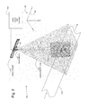
- FIG. 1 illustrates a first exemplary embodiment of a system for height estimation using tomosynthesis-like techniques with a single moving camera above a stationary object;
- FIG. 2 illustrates a second exemplary embodiment of a system for height estimation using tomosynthesis-like techniques with an object moving under a single stationary camera
- FIG. 3 illustrates a third exemplary embodiment of a system for height estimation using tomosynthesis-like techniques with multiple stationary cameras above a stationary object
- FIG. 4 illustrates the concept of tomosynthesis, in accordance with the embodiments of FIGS. 1-3 ;
- FIG. 5 is a flow chart of an example embodiment of a method to estimate the height profile of an object
- FIG. 6 illustrates an example embodiment of a plurality of raw images acquired using the system of FIG. 1 ;
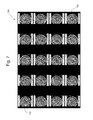
- FIG. 7 illustrates an example embodiment of a plurality of composite images generated from the raw images of FIG. 6 ;
- FIG. 8 illustrates an example plot of standard deviation versus composite image number for two example regions of interest in the composite images of FIG. 7 ;
- FIG. 9A illustrates an enlargement of the first composite image of FIG. 7 ;
- FIG. 9B illustrates an enlargement of the last composite image of FIG. 7 ;
- FIG. 10 illustrates an example embodiment of a height profile image generated from the raw images of FIG. 6 using the method of FIG. 5 ;
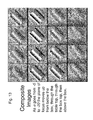
- FIGS. 11-13 illustrate an exemplary embodiment of the process of acquiring a plurality of images of a box to be characterized at multiple camera positions and of forming composite images from those acquired images
- FIGS. 14-17 illustrate an exemplary embodiment of the process of acquiring a plurality of images of a slanted ruler to be characterized at multiple camera positions and of forming composite images from those acquired images.
- Embodiments of the systems and methods described herein provide automatic measurement (estimation) of a height dimension of an object to be characterized such as, for example, a top surface of a cuboid or box-like object (e.g., a cardboard box or package) or lids of cans, using tomosynthesis-like techniques.
- the volume of the object may also be estimated.
- FIG. 1 illustrates a first exemplary embodiment of a system 100 for height estimation using tomosynthesis-like techniques.
- an operator places an object 120 to be measured on a measurement table 130 .
- An imaging device e.g., a video camera 110 , monochrome or color
- the camera 110 has a lens 112 with a field-of-view 115 adequate to see the entire top surface 121 of the largest object the system 100 is designed to measure. The region bounded by this largest object is called the measurement volume.
- a color camera may provide more discrimination between the object edges and the background than a monochrome camera.
- the camera 110 is spatially translated horizontally by means of a spatial translation mechanism 140 (e.g., a continuous or stepped motor drive, servo, screw or linear slide 141 having a motor 145 ) along a line (defined as the x-axis 151 of a right-handed Cartesian coordinate system xyz 150 ), and a sequence of equally-spaced images is acquired, each at a unique spatial location relative to the object to be characterized 120 .
- the translation mechanism 140 is operated by a vision engine and controller 160 which operationally interfaces to the translation mechanism 140 .
- the acquired images are referred to as raw images.
- the optics of the camera 110 are such that each raw image is substantially in focus over the entire measurement volume, in accordance with an embodiment of the present invention. Alternatively, distortion correction may be performed on the acquired images.
- the processing and control corresponding to the various methods and algorithms described herein may be performed by a vision engine 160 which may or may not be built-in to an enclosed system including the single camera.
- a vision engine and controller 160 may take the form of a digital signal processor or a software-controlled processor, for example, in order to receive and process acquired images as described herein to estimate height dimensions as well as to control the camera 110 (e.g., spatial translation and acquisition trigger) and a lighting device.
- the processing corresponding to the various methods and algorithms described herein may be performed by a personal computer (PC), for example, serially linked to the single camera.
- PC personal computer
- Such a PC may send commands to control a light source (ON/OFF sequence) and the camera translation, and may receive and process acquired images as described herein to estimate height dimensions.
- the single camera 110 may be stationary (mounted on a camera mount 142 ) as in the system 200 of FIG. 2 , and the object 120 may be moved beneath the camera 110 as images are acquired (e.g., on a conveyor belt 170 ).
- a plurality of cameras 110 ′ may be provided, as in the system 300 of FIG. 3 , which are spaced apart along a horizontal axis on a camera mount 143 above the object 120 .
- Each camera 110 of the plurality of cameras 110 ′ acquires a single image of the object 120 at its unique spatial position.
- Ambient light may be used during image acquisition or, alternatively, a strobe light may be used during image acquisition which is synchronized to the image capture trigger of the camera(s) 110 .
- the imaging device may be a high-speed imaging device (e.g., a high-speed CMOS camera) capable of acquiring images at rates of hundreds or possibly thousands of images per second.
- CMOS camera complementary metal-oxide-semiconductor
- Other types of imaging devices are possible as well, in accordance with certain other embodiments of the present invention.
- another type of imaging device may include a thermal imaging device.
- the total number of raw images acquired is 2N+1.
- FIG. 4 illustrates the concept of tomosynthesis.
- a camera represented by a pinhole plane 410 and a detector plane 420 is in a first position
- two points A and B aligned along the optical axis of the camera in the z-direction 430 are both projected onto the same point 440 on the detector 450 of the camera.
- the two points A and B are now projected onto the detector 450 of the camera at two different points 461 and 462 . That is, there is now a separation between the projection of point A and the projection of point B in the resultant acquired image.
- the point A will continue to move the same amount in the detector plane 420 and the point B will continue to move the same different amount in the detector plane 420 .
- the resultant acquired raw images are slid or shifted by an amount such that point A is aligned in all of the acquired images then, in the resultant composite image, point A will appear in focus and point B will appear blurred. This is because, when all points A are aligned, the points B are unaligned.
- point B will appear in focus and point A will appear blurred.
- the image shift from composite image to composite image is a fractional pixel shift and linear interpolation, for example, may be used to generate fractional pixel values between integer pixel locations.
- the above equations apply directly to the moving camera and stationary object scenario of FIG. 1 .
- To obtain the correct equations for the moving object and stationary camera scenario of FIG. 2 simply change the sign of ⁇ in the equations (e.g., ⁇ changes to ⁇ ).
- FIG. 5 is a flow chart of an example embodiment of a method 500 to estimate the height profile of an object.
- step 510 acquire a plurality of raw images of an object to be characterized using at least one imaging device (e.g., a camera), where the plurality of raw images are representative of a plurality of spatial shifts of the at least one imaging device relative to the object to be characterized.
- step 520 process the plurality of raw images to generate a plurality of composite images, where each composite image of the plurality of composite images corresponds to a unique image shift between spatially adjacent raw images and is made up of a plurality of image pixel locations.
- step 530 of the method 500 calculate a volatility parameter value (e.g., a standard deviation value) within a neighborhood (e.g., a predefined kernel of pixel locations, 5 ⁇ 5, 10 ⁇ 10) of at least one same image pixel location of the plurality of image pixel locations for each of the plurality of composite images.
- a volatility parameter value e.g., a standard deviation value
- filter e.g., low-pass filter
- step 550 determine which composite image of the plurality of composite images has a largest volatility parameter value for the at least one same image pixel location.
- step 560 of the method 500 transform the unique image shift, corresponding to the composite image having the largest volatility parameter value, into a height value representative of a height dimension of the at least one same image pixel location.
- step 570 generate a height value for each image pixel location of the plurality of image pixel locations to form a height profile image of the object to be characterized.
- step 580 compare the height profile image to at least one reference image to find any defects in the object to be characterized.
- the height profile image may be displayed on a display 180 of the system 100 , for example.
- Generating a height profile image with the method 500 of FIG. 5 involves determining the height of the imaged object at a large number of locations.
- the locations may form a square array of image pixel locations represented as an image.
- the value Z(p,q) can be offset and scaled appropriately and used as the pixel value at the image pixel location (p,q).
- s(i, p, q) be the standard deviation (one possible volatility parameter) of the pixel values in composite image i in the neighborhood of pixel (p,q).
- the neighborhood of the standard deviation operation is a kernel. For example, a 5 pixel by 5 pixel kernel centered on (p,q) for the standard deviation calculation may be chosen.
- the standard deviation tends to be relatively large for regions which are in focus, and relatively small for regions which are blurred (i.e., not in focus).
- the number of raw images and the kernel size may be optimized for any particular application.
- the standard deviation is not the only operator (volatility parameter) capable of being useful in determining focus.
- Other types of operators such as, for example, a 2D spatial gradient measurement approach and a rule-based approach are possible as well.
- FIG. 6 illustrates an example embodiment of a plurality of twenty-one raw images 600 acquired using the system 200 of FIG. 2 .
- the raw images 600 are that of a lid of a soda can and were acquired by the fixed camera 110 of FIG. 2 with a spacing of ⁇ between adjacent soda can lid acquisition positions.
- Each of the raw images is substantially in focus.
- the raw images could have been acquired using the system 100 of FIG. 1 or the system 300 of FIG. 3 as well.
- care is taken to minimize distortion across the field-of-view 115 such as, for example, barrel distortion or pin-cushion distortion which can appear in images.
- a low distortion lens 112 is used to minimize distortion.
- distortion produced by the lens 112 is measured and the resultant distortion in the raw images is subsequently taken out by performing distortion correction on the raw images.
- FIG. 7 illustrates an example embodiment of a plurality of twenty composite images 700 generated from the twenty-one raw images 600 of FIG. 6 .
- Each composite image is generated from all twenty-one raw images 600 by applying a unique image shift ⁇ to the raw images before integrating the raw images to form the composite image according to Equation (2).
- ⁇ For any particular same image pixel location in the composite images, one of the composite images will be most in focus for that image pixel location.
- the techniques described above are used to find that in-focus composite image and its corresponding unique image shift ⁇ .
- the total image shift from the first composite image 710 to the last composite image 720 is only about 2 pixels since sub-pixel interpolation is being used.
- sub-pixel interpolation may be employed for non-integer values of ⁇ .
- the composite image may have real number (floating point) pixel values to avoid introducing rounding errors to the composite image.
- Such sub-pixel interpolation can provide improved z-axis accuracy.
- the composite image may be an integer value image with more bits per pixel than the raw images.
- FIG. 8 illustrates an example plot 800 of standard deviation 810 versus composite image number 820 for two example regions of interest (ROI) 830 and 840 in the composite images 700 of FIG. 7 .
- Simply finding the maximum of the raw standard deviation s(i, p, q) in order to determine the in-focus value of i may not always be the optimal approach.
- the plot 800 may be somewhat noisy (bumpy), leading to errors in determining the true maximum standard deviation. It may be prudent, as in step 540 of the method 500 , to smooth the standard deviation data (volatility parameter values), via filtering, across the composite images to obtain a more accurate estimate of the value of i for the true maximum.
- FIG. 9A illustrates an enlargement of the first composite image 710 of FIG. 7 .
- FIG. 9B illustrates an enlargement of the last composite image 720 of FIG. 7 .
- the first composite image 710 is substantially more in focus than the last composite image 720 for most image pixel locations, indicating that the unique image shift ⁇ corresponding to first composite image 710 brings the soda can lid into focus better than the unique image shift ⁇ corresponding to the last composite image 710 .
- each image pixel location is to be considered separately according to the method 500 of FIG. 5 .
- FIG. 10 illustrates an example embodiment of a height profile image 1000 generated from the raw images 600 of FIG. 6 using the method 500 of FIG. 5 .
- the height or elevation is proportional to image brightness, with light image pixel locations being higher than dark image pixel locations.
- the height profile image 1000 is of somewhat poor quality (primarily because the system 100 is not optimized for the object to be characterized, as the object to be characterized is very thin compared to its distance from the camera and has a complex topography), the height profile image 1000 demonstrates the feasibility of the technique described herein.
- the final height profile image may be lower in resolution than the resolution of the composite images, in accordance with an embodiment of the present invention. For example, if a 5 pixel by 5 pixel kernel is used to find the height of a pixel, the same 5 ⁇ 5 pixel kernel may be used to average the final height image. Furthermore, a median filter may be used to eliminate artifacts in the height profile image (to eliminate outliers).
- a height profile image may be used in various applications such as, for example, object inspection and object dimensioning. For example, a height profile image may be compared to a stored reference image to find any defects in an object to be characterized. A height profile image may be used to find non-uniformities in objects that are supposed to be flat. A height profile image could be saved as a computer-aided design (CAD) file for subsequent use in manufacturing.
- CAD computer-aided design
- the above described systems may also be used to estimate the volume of a cuboid object (e.g., a box to be shipped) as well.
- the measurement volume is D ⁇ D ⁇ D and the distance from the pinhole to the table top is Z max (typically Z max ⁇ 3D).
- Z max typically Z max ⁇ 3D.
- This composite image is in focus at the top of the measurement volume, but out of focus everywhere else.
- the top of the box is a distance Z max ⁇ D+kd from the pinhole.
- a and b are the lengths of the edges of the box top in the image (that is, a and b are measured in pixels)
- images may be acquired along a non-linear or curved translation path (e.g., along a portion of a circular path).
- a non-linear path may help to blur certain edges more when desired, making the system more robust with respect to determining the height of the cuboid or box.
- an ultrasonic distance measurement device (like those used for the autofocus function of certain cameras) could be mounted directly above the box next to the camera scanning mechanism; by subtracting the measured distance to the box top from the known distance between the ultrasonic transmitter and the table top, the box height may be determined.
- a laser beam may be projected down onto the box top, with the beam slightly angled with respect to vertical, and the location of the beam in the camera images may be used to “triangulate” the box height. Either of these approaches may be used to determine the box height C [instead of using Eq. (7)], then Eqs. (8) would still give the other box dimensions, A and B.
- the tomosynthesis-like method allows for simultaneously reducing the imaging depth of field and adjusting the location of the in-focus plane. This is also possible, to a limited extent, by adjusting the focus and aperture of a conventional lens.
- a conventional lens (with motorized aperture and focus controls) may possibly be used to accomplish the same measurements as the tomosynthesis-like method.
- calculations indicate (and experiments confirm) that, for practical box measurement geometries, the depth of field with a conventional lens is too large to allow accurate box height estimation or significant background blurring.
- the scanning mechanism envisioned is straight-forward: a motorized linear slide moves the camera continuously and an encoder triggers image acquisitions at equally-spaced intervals.
- the camera exposure time is short enough to keep motion blur negligible. If ambient illumination is used for imaging and contains flicker, such as 120 Hz flicker due to a 60 Hz power line frequency, then the camera exposure time should be an integral number of flicker periods.
- a camera exposure time of 8.3 ms should fulfill both of these conditions for reasonable scanning times (of the order of a second).
- a strobe illuminator (LEDs or xenon) synchronized with image acquisition may also be incorporated into the system, to reduce the effects of ambient illumination and reduce motion blur.
- the system is compact and located above the box to be estimated. It may be possible to install the system in most places where a scale is currently installed without disrupting the environment around the scale. Many prior art systems require sensors surrounding the box.
- the processing corresponding to the various methods and algorithms described herein may be performed by a vision engine (processor) and controller 160 which may or may not be built-in to an enclosed system including the single camera.
- a vision engine and controller 160 may take the form of a digital signal processor or a software-controlled processor, for example, in order to receive and process acquired images as described herein to estimate cuboid dimensions.
- the processing corresponding to the various methods and algorithms described herein may be performed by a personal computer (PC), for example, serial linked to the single camera.
- PC personal computer
- Such a PC may send commands to control a light source (ON/OFF sequence) and the camera translation, and may receive and process acquired images as described herein to estimate cuboid dimensions.
- a plurality of raw images of an object to be characterized are acquired, where the plurality of raw images are representative of a plurality of spatial shifts of an imaging device relative to the object to be characterized.
- the raw images are processed to generate composite images, where each composite image corresponds to a unique image shift between spatially adjacent raw images.
- a volatility parameter value is calculated within a neighborhood of a same image pixel location for each composite image.
- the composite image having the largest volatility parameter value for the image pixel location is determined.
- a unique image shift, corresponding to the composite image having the largest volatility parameter value is transformed into a height value representative of a height dimension of the image pixel location.
Abstract
Description
P n =p 0+η(X−nδ)/Z
Q n =q 0 +ηY/Z, Equation (1)
-
- where η is the camera focal length (measured in pixels), and (p0,q0) is the principal point of the image sensor (the point where a line containing the pinhole and perpendicular to the image sensor intersects the image sensor).
I(p,q)=(2N+1)−1 ΣI n(p+nσ,q), Equation (2)
-
- where the summation is over all n, and σ represents a shift distance (image shift) (measured in pixels) along image rows between adjacent images. Equations (1) and (2) imply that the point object will, in general, appear at multiple locations in the composite image. Specifically, the point object will appear at locations (P′n,Q′n) in the composite image satisfying
P n =P′ n +nσ Equation (3)
Q n =Q′n.
- where the summation is over all n, and σ represents a shift distance (image shift) (measured in pixels) along image rows between adjacent images. Equations (1) and (2) imply that the point object will, in general, appear at multiple locations in the composite image. Specifically, the point object will appear at locations (P′n,Q′n) in the composite image satisfying
P′ n =p 0+(ηX/Z)−n[σ+(ηδ/Z)]
Q′ n =q 0+(ηY/Z). Equation (4)
σ=−ηδ/Z, Equation (5)
-
- then the term inside the brackets in the first of Eqs. (4) is zero, and the image of the point object appears at just a single point in the composite image, independent of n. For all other choices of σ, the point object will be imaged at multiple locations, spanning a distance (in pixels) along the composite image rows given by
β=|P′ N −P′ −N|=2N|σ+(ηδ/Z)|, Equation (6) - where the vertical bars denote absolute value. β is referred to herein as the blur diameter and is a measure of the extent of blurring in the composite image. Note that when σ satisfies the condition of Equation (5) there is no blurring of the point object (β=0).
- then the term inside the brackets in the first of Eqs. (4) is zero, and the image of the point object appears at just a single point in the composite image, independent of n. For all other choices of σ, the point object will be imaged at multiple locations, spanning a distance (in pixels) along the composite image rows given by
σi=σmin+(i/M)*(σmax−σmin), Equation (7)
-
- where the index i ranges from 0 to M, and the values of σmin and σmax are chosen to span the range of heights expected over the object to be characterized.
C=D−kd, where σfocus=σ(Z max −D+kd) Equation (7)
A=a(Z max −C)/η
B=b(Z max −C)/η. Equation (8)
-
- Z is the distance from the pinhole to the object,
- η is the focal length in pixels,
- δ is the distance the camera is translated in each step, and
- σ is the distance each image is shifted or translated before averaging to form a composite image.
Claims (17)
Priority Applications (1)
| Application Number | Priority Date | Filing Date | Title |
|---|---|---|---|
| US12/700,764 US8508591B2 (en) | 2010-02-05 | 2010-02-05 | System and method for estimating the height of an object using tomosynthesis-like techniques |
Applications Claiming Priority (1)
| Application Number | Priority Date | Filing Date | Title |
|---|---|---|---|
| US12/700,764 US8508591B2 (en) | 2010-02-05 | 2010-02-05 | System and method for estimating the height of an object using tomosynthesis-like techniques |
Publications (2)
| Publication Number | Publication Date |
|---|---|
| US20110193953A1 US20110193953A1 (en) | 2011-08-11 |
| US8508591B2 true US8508591B2 (en) | 2013-08-13 |
Family
ID=44353414
Family Applications (1)
| Application Number | Title | Priority Date | Filing Date |
|---|---|---|---|
| US12/700,764 Active 2032-02-25 US8508591B2 (en) | 2010-02-05 | 2010-02-05 | System and method for estimating the height of an object using tomosynthesis-like techniques |
Country Status (1)
| Country | Link |
|---|---|
| US (1) | US8508591B2 (en) |
Cited By (3)
| Publication number | Priority date | Publication date | Assignee | Title |
|---|---|---|---|---|
| US20150042791A1 (en) * | 2013-08-09 | 2015-02-12 | Postea, Inc. | Apparatus, systems and methods for enrollment of irregular shaped objects |
| US20190094151A1 (en) * | 2014-12-08 | 2019-03-28 | Koh Young Technology Inc. | Method of inspecting a terminal of a component mounted on a substrate and substrate inspection apparatus |
| TWI666426B (en) * | 2018-10-26 | 2019-07-21 | National Taiwan University Of Science And Technology | Liquid level detecting method |
Families Citing this family (7)
| Publication number | Priority date | Publication date | Assignee | Title |
|---|---|---|---|---|
| US9015612B2 (en) * | 2010-11-09 | 2015-04-21 | Sony Corporation | Virtual room form maker |
| KR20140116551A (en) * | 2012-01-31 | 2014-10-02 | 쓰리엠 이노베이티브 프로퍼티즈 캄파니 | Method and apparatus for measuring the three dimensional structure of a surface |
| US9554094B1 (en) * | 2012-11-30 | 2017-01-24 | Cognex Corporation | System and method for determining a displaced substrate with a vision system |
| CN103308452B (en) * | 2013-05-27 | 2015-05-06 | 中国科学院自动化研究所 | Optical projection tomography image capturing method based on depth-of-field fusion |
| EP3469990A1 (en) * | 2017-10-16 | 2019-04-17 | Koninklijke Philips N.V. | Determination of a subject profile with a camera |
| DE102019128814B4 (en) * | 2019-10-25 | 2021-05-20 | Sick Ag | Camera for detecting an object flow and method for determining the height of objects |
| US20230175845A1 (en) * | 2021-12-08 | 2023-06-08 | Theodore Allen | Device and System for Aqueous Wave Measurement |
Citations (45)
| Publication number | Priority date | Publication date | Assignee | Title |
|---|---|---|---|---|
| GB191301535A (en) | 1912-02-02 | 1913-05-08 | Zeiss Carl | Improvements in Telemeters. |
| GB445716A (en) | 1934-10-23 | 1936-04-17 | Osborn Maitland Miller | Improvements in or relating to plotting maps |
| GB468481A (en) | 1936-07-09 | 1937-07-06 | Barr & Stroud Ltd | Improvements in or connected with stereoscopic observation instruments such as stereoscopic rangefinders |
| GB756994A (en) | 1953-05-29 | 1956-09-12 | Roelof Roelofs | An improved device for determining the polar coordinates of points in a plane surface, and a radial triangulator in which this device is employed |
| GB786534A (en) | 1955-06-30 | 1957-11-20 | Barr & Stroud Ltd | Improvements relating to rangefinders, and like optical instruments |
| JPS58130361A (en) | 1982-01-29 | 1983-08-03 | Canon Inc | Image reader |
| JPS6310280A (en) | 1986-07-01 | 1988-01-16 | Omron Tateisi Electronics Co | 3-eye stereoscopic device |
| EP0364614A1 (en) | 1988-10-17 | 1990-04-25 | Siemens Aktiengesellschaft | Method of recognising the spatial position and orientation of already known objects |
| US5042015A (en) | 1989-09-01 | 1991-08-20 | Quantronix, Inc. | Measuring method and apparatus |
| EP0477078A1 (en) | 1990-09-18 | 1992-03-25 | AEROSPATIALE Société Nationale Industrielle | Method and device for guiding gripping means of a robot |
| US5105392A (en) | 1989-09-01 | 1992-04-14 | Quantronix, Inc. | Measuring method and apparatus |
| US5220536A (en) | 1989-09-01 | 1993-06-15 | Quantronix, Inc. | Measuring method and apparatus |
| US5422861A (en) | 1989-09-01 | 1995-06-06 | Quantronix, Inc. | Measuring method and apparatus |
| WO1996017258A2 (en) | 1994-12-01 | 1996-06-06 | Novus Limited | Optical position sensing system |
| US5530420A (en) | 1993-12-27 | 1996-06-25 | Fuji Jukogyo Kabushiki Kaisha | Running guide apparatus for vehicle capable of keeping safety at passing through narrow path and the method thereof |
| JPH08210851A (en) | 1995-02-02 | 1996-08-20 | Asia Kosoku Kk | Three dimensional digital plotter |
| US5606534A (en) | 1989-09-01 | 1997-02-25 | Quantronix, Inc. | Laser-based dimensioning system |
| US5636028A (en) | 1995-06-29 | 1997-06-03 | Quantronix, Inc. | In-motion dimensioning system for cuboidal objects |
| US5719678A (en) | 1994-07-26 | 1998-02-17 | Intermec Corporation | Volumetric measurement of a parcel using a CCD line scanner and height sensor |
| US5744793A (en) | 1994-02-28 | 1998-04-28 | Electro-Pro, Inc. | Triangulation position-detection and integrated dispensing valve |
| US5808912A (en) | 1996-12-31 | 1998-09-15 | Pitney Bowes Inc. | Method for dimensional weighing utilizing point determination |
| DE19748062A1 (en) | 1997-10-31 | 1999-05-12 | Bernward Maehner | 3D optical measuring of object with grating projecting light pattern on object |
| US5914463A (en) | 1996-12-31 | 1999-06-22 | Pitney Bowes Inc. | Low cost dimensional determining system |
| WO1999034336A1 (en) | 1997-12-29 | 1999-07-08 | The United States Of America, Represented By The Administrator Of The National Aeronautics And Space Administration (Nasa) | Triangle geometry processing for surface modeling and cartesian grid generation |
| FR2783068A1 (en) | 1998-09-03 | 2000-03-10 | Cit Alcatel | Modelling three-dimensional data from photographs uses map with contours to provide ground plan and altitude, and stereoscopic photographs for building size |
| US6049386A (en) | 1995-06-29 | 2000-04-11 | Quantronix, Inc. | In-motion dimensioning system and method for cuboidal objects |
| EP1100048A1 (en) | 1999-11-12 | 2001-05-16 | Société N3DI S.A.R.L. | Automatic building process of a digital model using stereoscopic image couples |
| JP2002044686A (en) | 2000-07-25 | 2002-02-08 | Joho Kagaku Kenkyusho:Kk | Simple production technique for stereoscopic image through introduction of digital movie in personal computer |
| US20020039187A1 (en) * | 2000-06-30 | 2002-04-04 | Thermo Radiometrie Oy | Determining surface shapes |
| JP2002148732A (en) | 2000-11-15 | 2002-05-22 | Nippon Telegr & Teleph Corp <Ntt> | Three-dimensional moving picture input device |
| CA2346278A1 (en) | 2001-05-04 | 2002-11-04 | Institut National D'optique | Portable apparatus for 3-dimensional scanning |
| US20020162886A1 (en) | 2001-05-04 | 2002-11-07 | Michel Arsenault | Portable apparatus for 3-dimensional scanning |
| US6480301B1 (en) | 1999-11-15 | 2002-11-12 | Lexmark International, Inc. | Method and apparatus for gamut boundary determination |
| US20020181762A1 (en) * | 2001-05-30 | 2002-12-05 | Mitutoyo Corporation | Systems and methods for constructing an image having an extended depth of field |
| WO2003002935A1 (en) | 2001-06-29 | 2003-01-09 | Square D Company | Overhead dimensioning system and method |
| ES2184541A1 (en) | 1999-12-02 | 2003-04-01 | Univ Las Palmas Gran Canaria | Interactive mobile robot for museum services |
| US6554189B1 (en) | 1996-10-07 | 2003-04-29 | Metrologic Instruments, Inc. | Automated system and method for identifying and measuring packages transported through a laser scanning tunnel |
| US20040022418A1 (en) | 2002-07-31 | 2004-02-05 | Akihiro Oota | Pattern-matching processing method and image processing apparatus |
| WO2004072578A1 (en) | 2003-02-05 | 2004-08-26 | Quantronix, Inc. | Dimensioning system and method of dimensioning |
| US20040246333A1 (en) | 2003-06-03 | 2004-12-09 | Steuart Leonard P. (Skip) | Digital 3D/360 degree camera system |
| US20060067572A1 (en) | 2004-09-14 | 2006-03-30 | Tattile, L.L.C. | Object imaging system |
| DE102004053416A1 (en) | 2004-11-05 | 2006-05-11 | Robert Bosch Gmbh | Stereoscopic distance measurement system to determine distance of object from motor vehicle has splitter mirror element to deflect first part of virtual beam bundle from camera which is then overlapped by second part of beam bundle |
| WO2008057504A2 (en) | 2006-11-06 | 2008-05-15 | Aman James A | Load tracking system based on self- tracking forklift |
| DE102007025373B3 (en) | 2007-05-31 | 2008-07-17 | Sick Ag | Visual monitoring device for use in e.g. automated guided vehicle system, has evaluation unit formed such that unit tests separation information based on another separation information of plausibility |
| US20100182406A1 (en) * | 2007-07-12 | 2010-07-22 | Benitez Ana B | System and method for three-dimensional object reconstruction from two-dimensional images |
-
2010
- 2010-02-05 US US12/700,764 patent/US8508591B2/en active Active
Patent Citations (52)
| Publication number | Priority date | Publication date | Assignee | Title |
|---|---|---|---|---|
| GB191301535A (en) | 1912-02-02 | 1913-05-08 | Zeiss Carl | Improvements in Telemeters. |
| GB445716A (en) | 1934-10-23 | 1936-04-17 | Osborn Maitland Miller | Improvements in or relating to plotting maps |
| GB468481A (en) | 1936-07-09 | 1937-07-06 | Barr & Stroud Ltd | Improvements in or connected with stereoscopic observation instruments such as stereoscopic rangefinders |
| GB756994A (en) | 1953-05-29 | 1956-09-12 | Roelof Roelofs | An improved device for determining the polar coordinates of points in a plane surface, and a radial triangulator in which this device is employed |
| GB786534A (en) | 1955-06-30 | 1957-11-20 | Barr & Stroud Ltd | Improvements relating to rangefinders, and like optical instruments |
| JPS58130361A (en) | 1982-01-29 | 1983-08-03 | Canon Inc | Image reader |
| JPS6310280A (en) | 1986-07-01 | 1988-01-16 | Omron Tateisi Electronics Co | 3-eye stereoscopic device |
| EP0364614A1 (en) | 1988-10-17 | 1990-04-25 | Siemens Aktiengesellschaft | Method of recognising the spatial position and orientation of already known objects |
| US5850370A (en) | 1989-09-01 | 1998-12-15 | Quantronix, Inc. | Laser-based dimensioning system |
| US5105392A (en) | 1989-09-01 | 1992-04-14 | Quantronix, Inc. | Measuring method and apparatus |
| US5220536A (en) | 1989-09-01 | 1993-06-15 | Quantronix, Inc. | Measuring method and apparatus |
| US5422861A (en) | 1989-09-01 | 1995-06-06 | Quantronix, Inc. | Measuring method and apparatus |
| US6298009B1 (en) | 1989-09-01 | 2001-10-02 | Quantronix, Inc. | Object measuring and weighing apparatus and method for determining conveyance speed |
| US5606534A (en) | 1989-09-01 | 1997-02-25 | Quantronix, Inc. | Laser-based dimensioning system |
| US6611787B2 (en) | 1989-09-01 | 2003-08-26 | Quantronix, Inc. | Object measuring and weighing apparatus |
| US5042015A (en) | 1989-09-01 | 1991-08-20 | Quantronix, Inc. | Measuring method and apparatus |
| EP0477078A1 (en) | 1990-09-18 | 1992-03-25 | AEROSPATIALE Société Nationale Industrielle | Method and device for guiding gripping means of a robot |
| USRE37610E1 (en) | 1993-12-27 | 2002-03-26 | Fuji Jukogyo Kabushiki Kaisha | Running guide apparatus for vehicle capable of keeping safety at passing through narrow path and the method thereof |
| US5530420A (en) | 1993-12-27 | 1996-06-25 | Fuji Jukogyo Kabushiki Kaisha | Running guide apparatus for vehicle capable of keeping safety at passing through narrow path and the method thereof |
| US5744793A (en) | 1994-02-28 | 1998-04-28 | Electro-Pro, Inc. | Triangulation position-detection and integrated dispensing valve |
| US5719678A (en) | 1994-07-26 | 1998-02-17 | Intermec Corporation | Volumetric measurement of a parcel using a CCD line scanner and height sensor |
| WO1996017258A2 (en) | 1994-12-01 | 1996-06-06 | Novus Limited | Optical position sensing system |
| JPH08210851A (en) | 1995-02-02 | 1996-08-20 | Asia Kosoku Kk | Three dimensional digital plotter |
| US6049386A (en) | 1995-06-29 | 2000-04-11 | Quantronix, Inc. | In-motion dimensioning system and method for cuboidal objects |
| US5636028A (en) | 1995-06-29 | 1997-06-03 | Quantronix, Inc. | In-motion dimensioning system for cuboidal objects |
| US6554189B1 (en) | 1996-10-07 | 2003-04-29 | Metrologic Instruments, Inc. | Automated system and method for identifying and measuring packages transported through a laser scanning tunnel |
| US5808912A (en) | 1996-12-31 | 1998-09-15 | Pitney Bowes Inc. | Method for dimensional weighing utilizing point determination |
| US5914463A (en) | 1996-12-31 | 1999-06-22 | Pitney Bowes Inc. | Low cost dimensional determining system |
| DE19748062A1 (en) | 1997-10-31 | 1999-05-12 | Bernward Maehner | 3D optical measuring of object with grating projecting light pattern on object |
| US6445390B1 (en) | 1997-12-29 | 2002-09-03 | The United States Of America As Represented By The Adminstrator Of The National Aeronautics And Space Administration | Triangle geometry processing for surface modeling and cartesian grid generation |
| WO1999034336A1 (en) | 1997-12-29 | 1999-07-08 | The United States Of America, Represented By The Administrator Of The National Aeronautics And Space Administration (Nasa) | Triangle geometry processing for surface modeling and cartesian grid generation |
| FR2783068A1 (en) | 1998-09-03 | 2000-03-10 | Cit Alcatel | Modelling three-dimensional data from photographs uses map with contours to provide ground plan and altitude, and stereoscopic photographs for building size |
| EP1100048A1 (en) | 1999-11-12 | 2001-05-16 | Société N3DI S.A.R.L. | Automatic building process of a digital model using stereoscopic image couples |
| US6480301B1 (en) | 1999-11-15 | 2002-11-12 | Lexmark International, Inc. | Method and apparatus for gamut boundary determination |
| ES2184541A1 (en) | 1999-12-02 | 2003-04-01 | Univ Las Palmas Gran Canaria | Interactive mobile robot for museum services |
| US20020039187A1 (en) * | 2000-06-30 | 2002-04-04 | Thermo Radiometrie Oy | Determining surface shapes |
| JP2002044686A (en) | 2000-07-25 | 2002-02-08 | Joho Kagaku Kenkyusho:Kk | Simple production technique for stereoscopic image through introduction of digital movie in personal computer |
| JP2002148732A (en) | 2000-11-15 | 2002-05-22 | Nippon Telegr & Teleph Corp <Ntt> | Three-dimensional moving picture input device |
| CA2346278A1 (en) | 2001-05-04 | 2002-11-04 | Institut National D'optique | Portable apparatus for 3-dimensional scanning |
| US20020162886A1 (en) | 2001-05-04 | 2002-11-07 | Michel Arsenault | Portable apparatus for 3-dimensional scanning |
| US20020181762A1 (en) * | 2001-05-30 | 2002-12-05 | Mitutoyo Corporation | Systems and methods for constructing an image having an extended depth of field |
| US20040240754A1 (en) | 2001-06-29 | 2004-12-02 | Smith Melvyn Lionel | Overhead dimensioning system and method |
| WO2003002935A1 (en) | 2001-06-29 | 2003-01-09 | Square D Company | Overhead dimensioning system and method |
| US20040022418A1 (en) | 2002-07-31 | 2004-02-05 | Akihiro Oota | Pattern-matching processing method and image processing apparatus |
| WO2004072578A1 (en) | 2003-02-05 | 2004-08-26 | Quantronix, Inc. | Dimensioning system and method of dimensioning |
| US6850464B2 (en) | 2003-02-05 | 2005-02-01 | Quantronix, Inc. | Dimensioning system and method of dimensioning |
| US20040246333A1 (en) | 2003-06-03 | 2004-12-09 | Steuart Leonard P. (Skip) | Digital 3D/360 degree camera system |
| US20060067572A1 (en) | 2004-09-14 | 2006-03-30 | Tattile, L.L.C. | Object imaging system |
| DE102004053416A1 (en) | 2004-11-05 | 2006-05-11 | Robert Bosch Gmbh | Stereoscopic distance measurement system to determine distance of object from motor vehicle has splitter mirror element to deflect first part of virtual beam bundle from camera which is then overlapped by second part of beam bundle |
| WO2008057504A2 (en) | 2006-11-06 | 2008-05-15 | Aman James A | Load tracking system based on self- tracking forklift |
| DE102007025373B3 (en) | 2007-05-31 | 2008-07-17 | Sick Ag | Visual monitoring device for use in e.g. automated guided vehicle system, has evaluation unit formed such that unit tests separation information based on another separation information of plausibility |
| US20100182406A1 (en) * | 2007-07-12 | 2010-07-22 | Benitez Ana B | System and method for three-dimensional object reconstruction from two-dimensional images |
Non-Patent Citations (13)
| Title |
|---|
| AccuVision AV6010 Camera Bar Code Scanning System with Optional Dimensioning, http://www.accusort.com/products/barcodescanners/longrange/av6010.html, Apr. 21, 2010. |
| CNS810-Capture package data quickly and accurately, www.mt.com/cargoscan, Jun. 2006, Mettler-Toledo, Inc., Columbus, OH. |
| CNS810—Capture package data quickly and accurately, www.mt.com/cargoscan, Jun. 2006, Mettler-Toledo, Inc., Columbus, OH. |
| CS5400 BarCoded YardStick Systems-Simple, Low Cost Dimensioning, http://us.mt.com/us/en?homeproducts/Transport-and-Logistics-Solutions/parcel-dimensioners-cargoscan/Static-dimensioning-weighing/SC5400-Dimensioner.html, Apr. 21, 2010, www.mt.com/cargoscan, Mettler-Toledo Cargoscan AS, Inc., Norway. |
| CS5400 BarCoded YardStick Systems—Simple, Low Cost Dimensioning, http://us.mt.com/us/en?homeproducts/Transport—and—Logistics—Solutions/parcel—dimensioners—cargoscan/Static—dimensioning—weighing/SC5400—Dimensioner.html, Apr. 21, 2010, www.mt.com/cargoscan, Mettler-Toledo Cargoscan AS, Inc., Norway. |
| CS5400 BarCoded YardStick-Easy measuring for getting started, www.mt.com/cargoscan, Dec. 2006, Mettler-Toledo Cargoscan AS, Inc., Norway. |
| CS5400 BarCoded YardStick—Easy measuring for getting started, www.mt.com/cargoscan, Dec. 2006, Mettler-Toledo Cargoscan AS, Inc., Norway. |
| Dimensioning, http://www.accusort.com/applications/dimensioning.html, Apr. 21, 2010. |
| DM3500 Package Dimensioning System, http://www.accusort.com/applications/dimensioners/dm3500.html, Apr. 21, 2010. |
| ExpressCube Countertop Series, www.expresscube.com, 2006, Ontario, CA. |
| S. Gondrom, S. Schropfer, FhG ITFP, Saarbrucken, D., Digital computed laminography and tomosynthesis-functional principles and industrial applications, NDT.net, info@ndt.net, Jul. 1999, vol. 4 No. 7, 5 pages. |
| S. Gondrom, S. Schropfer, FhG ITFP, Saarbrucken, D., Digital computed laminography and tomosynthesis—functional principles and industrial applications, NDT.net, info@ndt.net, Jul. 1999, vol. 4 No. 7, 5 pages. |
| System Solutions, VMS420/520/ VMS520, https://mysick.com/partnerPortal/ProductCatalog/DataSheet.aspx?ProductID=41349, Nov. 2006, pp. 1-10, Germany. |
Cited By (4)
| Publication number | Priority date | Publication date | Assignee | Title |
|---|---|---|---|---|
| US20150042791A1 (en) * | 2013-08-09 | 2015-02-12 | Postea, Inc. | Apparatus, systems and methods for enrollment of irregular shaped objects |
| US20190094151A1 (en) * | 2014-12-08 | 2019-03-28 | Koh Young Technology Inc. | Method of inspecting a terminal of a component mounted on a substrate and substrate inspection apparatus |
| US10533952B2 (en) * | 2014-12-08 | 2020-01-14 | Koh Young Technology Inc. | Method of inspecting a terminal of a component mounted on a substrate and substrate inspection apparatus |
| TWI666426B (en) * | 2018-10-26 | 2019-07-21 | National Taiwan University Of Science And Technology | Liquid level detecting method |
Also Published As
| Publication number | Publication date |
|---|---|
| US20110193953A1 (en) | 2011-08-11 |
Similar Documents
| Publication | Publication Date | Title |
|---|---|---|
| US8508591B2 (en) | System and method for estimating the height of an object using tomosynthesis-like techniques | |
| EP1462992B1 (en) | System and method for shape reconstruction from optical images | |
| US6549288B1 (en) | Structured-light, triangulation-based three-dimensional digitizer | |
| US8866891B2 (en) | Method for the non-destructive inspection of a mechanical part | |
| US9292925B2 (en) | Imaging system and control method thereof | |
| US6314201B1 (en) | Automatic X-ray determination of solder joint and view delta Z values from a laser mapped reference surface for circuit board inspection using X-ray laminography | |
| US20030035576A1 (en) | Automatic X-ray determination of solder joint and view Delta Z values from a laser mapped reference surface for circuit board inspection using X-ray laminography | |
| JP5014003B2 (en) | Inspection apparatus and method | |
| FR2856170A1 (en) | Radiographic imaging process for patient, involves establishing geometric characteristic for model representing object using geometric model having information related to three dimensional form of objects of same nature | |
| JPH02501411A (en) | Automatic laminography system for testing electronics | |
| US9886764B2 (en) | Image acquisition system, image acquisition method, and inspection system | |
| EP1604194A1 (en) | Optical inspection system and method for displaying imaged objects in greater than two dimensions | |
| US9157874B2 (en) | System and method for automated x-ray inspection | |
| JP4610590B2 (en) | X-ray inspection apparatus, X-ray inspection method, and X-ray inspection program | |
| US6115449A (en) | Apparatus for quantitative stereoscopic radiography | |
| JP2018509600A (en) | Gap resolution for linear detector arrays | |
| JP2011145160A (en) | Device and method for multi-focus inspection | |
| JP4310374B2 (en) | Method for measuring annual ring width or density of wood or wooden cultural assets | |
| JP6921036B2 (en) | A laser calibrator, a method for calibrating the laser, and an image input device including the laser calibrator. | |
| JP2023058641A (en) | Light transmission measurement device | |
| Boone et al. | Sinusoidal modulation analysis for optical system MTF measurements | |
| JP2013002968A (en) | Component height measuring method and apparatus therefor | |
| JP4449596B2 (en) | Mounting board inspection equipment | |
| JPH0855887A (en) | Laminograph | |
| US6118843A (en) | Quantitative stereoscopic radiography method |
Legal Events
| Date | Code | Title | Description |
|---|---|---|---|
| AS | Assignment |
Owner name: APPLIED VISION COMPANY, LLC, OHIO Free format text: ASSIGNMENT OF ASSIGNORS INTEREST;ASSIGNORS:SONES, RICHARD A.;SEBENY, CARL E.;SIGNING DATES FROM 20100303 TO 20100304;REEL/FRAME:024049/0977 |
|
| AS | Assignment |
Owner name: APPLIED VISION CORPORATION, OHIO Free format text: ASSIGNMENT OF ASSIGNORS INTEREST;ASSIGNORS:SONES, RICHARD A.;SEBENY, CARL E.;REEL/FRAME:024417/0088 Effective date: 20100505 |
|
| AS | Assignment |
Owner name: APPLIED VISION CORPORATION, OHIO Free format text: CORRECTIVE ASSIGNMENT TO CORRECT THE NAME OF ASSIGNEE PREVIOUSLY RECORDED ON REEL 024049 FRAME 0977. ASSIGNOR(S) HEREBY CONFIRMS THE CORRECT NAME OF ASSIGNEE IS APPLIED VISION CORPORATION. INFORMATION PROVIDED IS TRUE, COPY SUBMITTED IS TRUE COPY OF ORIGINAL.;ASSIGNORS:SONES, RICHARD A.;SEBENY, CARL E.;SIGNING DATES FROM 20100729 TO 20100802;REEL/FRAME:024851/0787 |
|
| STCF | Information on status: patent grant |
Free format text: PATENTED CASE |
|
| CC | Certificate of correction | ||
| FPAY | Fee payment |
Year of fee payment: 4 |
|
| FEPP | Fee payment procedure |
Free format text: ENTITY STATUS SET TO UNDISCOUNTED (ORIGINAL EVENT CODE: BIG.); ENTITY STATUS OF PATENT OWNER: LARGE ENTITY Free format text: 7.5 YR SURCHARGE - LATE PMT W/IN 6 MO, LARGE ENTITY (ORIGINAL EVENT CODE: M1555); ENTITY STATUS OF PATENT OWNER: LARGE ENTITY |
|
| MAFP | Maintenance fee payment |
Free format text: PAYMENT OF MAINTENANCE FEE, 8TH YEAR, LARGE ENTITY (ORIGINAL EVENT CODE: M1552); ENTITY STATUS OF PATENT OWNER: LARGE ENTITY Year of fee payment: 8 |