US8505406B2 - Control device - Google Patents
Control device Download PDFInfo
- Publication number
- US8505406B2 US8505406B2 US11/844,939 US84493907A US8505406B2 US 8505406 B2 US8505406 B2 US 8505406B2 US 84493907 A US84493907 A US 84493907A US 8505406 B2 US8505406 B2 US 8505406B2
- Authority
- US
- United States
- Prior art keywords
- stick
- actuator
- pivot axis
- control device
- axis
- Prior art date
- Legal status (The legal status is an assumption and is not a legal conclusion. Google has not performed a legal analysis and makes no representation as to the accuracy of the status listed.)
- Active, expires
Links
Images


Classifications
-
- G—PHYSICS
- G05—CONTROLLING; REGULATING
- G05G—CONTROL DEVICES OR SYSTEMS INSOFAR AS CHARACTERISED BY MECHANICAL FEATURES ONLY
- G05G1/00—Controlling members, e.g. knobs or handles; Assemblies or arrangements thereof; Indicating position of controlling members
- G05G1/04—Controlling members for hand actuation by pivoting movement, e.g. levers
-
- G—PHYSICS
- G05—CONTROLLING; REGULATING
- G05G—CONTROL DEVICES OR SYSTEMS INSOFAR AS CHARACTERISED BY MECHANICAL FEATURES ONLY
- G05G9/00—Manually-actuated control mechanisms provided with one single controlling member co-operating with two or more controlled members, e.g. selectively, simultaneously
- G05G9/02—Manually-actuated control mechanisms provided with one single controlling member co-operating with two or more controlled members, e.g. selectively, simultaneously the controlling member being movable in different independent ways, movement in each individual way actuating one controlled member only
- G05G9/04—Manually-actuated control mechanisms provided with one single controlling member co-operating with two or more controlled members, e.g. selectively, simultaneously the controlling member being movable in different independent ways, movement in each individual way actuating one controlled member only in which movement in two or more ways can occur simultaneously
- G05G9/047—Manually-actuated control mechanisms provided with one single controlling member co-operating with two or more controlled members, e.g. selectively, simultaneously the controlling member being movable in different independent ways, movement in each individual way actuating one controlled member only in which movement in two or more ways can occur simultaneously the controlling member being movable by hand about orthogonal axes, e.g. joysticks
- G05G2009/0474—Manually-actuated control mechanisms provided with one single controlling member co-operating with two or more controlled members, e.g. selectively, simultaneously the controlling member being movable in different independent ways, movement in each individual way actuating one controlled member only in which movement in two or more ways can occur simultaneously the controlling member being movable by hand about orthogonal axes, e.g. joysticks characterised by means converting mechanical movement into electric signals
- G05G2009/04762—Force transducer, e.g. strain gauge
-
- G—PHYSICS
- G05—CONTROLLING; REGULATING
- G05G—CONTROL DEVICES OR SYSTEMS INSOFAR AS CHARACTERISED BY MECHANICAL FEATURES ONLY
- G05G9/00—Manually-actuated control mechanisms provided with one single controlling member co-operating with two or more controlled members, e.g. selectively, simultaneously
- G05G9/02—Manually-actuated control mechanisms provided with one single controlling member co-operating with two or more controlled members, e.g. selectively, simultaneously the controlling member being movable in different independent ways, movement in each individual way actuating one controlled member only
- G05G9/04—Manually-actuated control mechanisms provided with one single controlling member co-operating with two or more controlled members, e.g. selectively, simultaneously the controlling member being movable in different independent ways, movement in each individual way actuating one controlled member only in which movement in two or more ways can occur simultaneously
- G05G9/047—Manually-actuated control mechanisms provided with one single controlling member co-operating with two or more controlled members, e.g. selectively, simultaneously the controlling member being movable in different independent ways, movement in each individual way actuating one controlled member only in which movement in two or more ways can occur simultaneously the controlling member being movable by hand about orthogonal axes, e.g. joysticks
- G05G2009/04766—Manually-actuated control mechanisms provided with one single controlling member co-operating with two or more controlled members, e.g. selectively, simultaneously the controlling member being movable in different independent ways, movement in each individual way actuating one controlled member only in which movement in two or more ways can occur simultaneously the controlling member being movable by hand about orthogonal axes, e.g. joysticks providing feel, e.g. indexing means, means to create counterforce
-
- Y—GENERAL TAGGING OF NEW TECHNOLOGICAL DEVELOPMENTS; GENERAL TAGGING OF CROSS-SECTIONAL TECHNOLOGIES SPANNING OVER SEVERAL SECTIONS OF THE IPC; TECHNICAL SUBJECTS COVERED BY FORMER USPC CROSS-REFERENCE ART COLLECTIONS [XRACs] AND DIGESTS
- Y10—TECHNICAL SUBJECTS COVERED BY FORMER USPC
- Y10T—TECHNICAL SUBJECTS COVERED BY FORMER US CLASSIFICATION
- Y10T74/00—Machine element or mechanism
- Y10T74/20—Control lever and linkage systems
- Y10T74/20012—Multiple controlled elements
- Y10T74/20018—Transmission control
- Y10T74/2014—Manually operated selector [e.g., remotely controlled device, lever, push button, rotary dial, etc.]
-
- Y—GENERAL TAGGING OF NEW TECHNOLOGICAL DEVELOPMENTS; GENERAL TAGGING OF CROSS-SECTIONAL TECHNOLOGIES SPANNING OVER SEVERAL SECTIONS OF THE IPC; TECHNICAL SUBJECTS COVERED BY FORMER USPC CROSS-REFERENCE ART COLLECTIONS [XRACs] AND DIGESTS
- Y10—TECHNICAL SUBJECTS COVERED BY FORMER USPC
- Y10T—TECHNICAL SUBJECTS COVERED BY FORMER US CLASSIFICATION
- Y10T74/00—Machine element or mechanism
- Y10T74/20—Control lever and linkage systems
- Y10T74/20012—Multiple controlled elements
- Y10T74/20201—Control moves in two planes
Definitions
- the present invention relates to a control device comprising: a reference frame; a stick; a pivot mounting the stick to the reference frame, the pivot defining a pivot axis; and an actuator for rotating the stick about the pivot axis.
- a first known control device of this kind is described in US 2006/0254377.
- the stick is driven about two perpendicular pivot axes (A, B) by respective rotary actuators.
- a balance weight is provided on the A-axis in order to provide vertical mass balance about the B-axis.
- the balance weight ensures that there is no net induced moment about the B-axis when the device is subjected to a vertical acceleration perpendicular to the A and B axes.
- a first problem with this arrangement is that the balance weight adds to the total weight of the device.
- a second problem is that the balance weight adds to the total volume of the device.
- a third problem is that the device is not horizontally mass balanced. Therefore, if the device is subjected to a horizontal acceleration, then there will be a net induced moment about the A or B axis. This mass imbalance must be compensated by one or both of the actuators, which adds complexity to the system.
- a control device comprises: a reference frame; a stick; a pivot mounting the stick to the reference frame and defining a pivot axis; and an actuator for rotating the stick about the pivot axis, wherein the centres of mass of the actuator and the stick are offset from the pivot axis such that if the control device is subjected to an acceleration orthogonal to the pivot axis, then the mass of the actuator and the mass of the stick generate moments about the pivot axis which act in opposite directions.
- the mass of the stick can be at least partially balanced by the mass of the actuator without requiring an additional balance weight.
- a line passing through the pivot axis and the centre of mass of the stick also passes through the actuator.
- this line passes substantially through the centre of mass of the actuator. This enables the device to be mass balanced with respect to both vertical and horizontal acceleration of the device (in the case where the pivot axis is horizontal).
- the line passes substantially through the centre of mass of the actuator, then the device is mass balanced with respect to two axes which are perpendicular to the pivot axis.
- the centre of mass of the actuator may be slightly offset from this line and still provide an element of mass balance.
- the actuator may be a linear actuator (such as a hydraulic piston or linear electric actuator) but more preferably the actuator is a rotary actuator having a stator coupled to the slick and a rotor coupled to the reference frame by a drive link and configured to rotate relative to the stator about a drive axis which is not co-linear with the pivot axis.
- a linear actuator such as a hydraulic piston or linear electric actuator
- the actuator is a rotary actuator having a stator coupled to the slick and a rotor coupled to the reference frame by a drive link and configured to rotate relative to the stator about a drive axis which is not co-linear with the pivot axis.
- a control device comprises: a reference frame; a stick; a pivot mounting the stick to the reference frame and defining a pivot axis; and a rotary actuator having a stator coupled to the stick and a rotor coupled to the reference frame by a drive link and configured to rotate relative to the stator about a drive axis which is not co-linear with the pivot axis.
- a rotary actuator In contrast with the devices described in US 2006/0254377 and U.S. Pat. No. 6,708,580 the drive axis of the rotary actuator is not co-linear with the pivot axis, enabling a more mass balanced arrangement. Also, a rotary actuator is typically more compact and lighter than a linear actuator, and is also typically easier to backdrive.
- the drive link is pivotally coupled to the rotor by a first drive pivot and to the reference frame by a second drive pivot.
- the drive axis is not parallel with the pivot axis. For instance it may lie at a perpendicular or acute angle with the pivot axis. In other embodiments of the invention the drive axis is substantially parallel with the pivot axis.
- the device is substantially mass balanced about the pivot axis.
- FIG. 1 is a front upper view of a first one-axis device in a nominal position
- FIG. 2 is a rear 3 ⁇ 4 view of the first one-axis device in the nominal position
- FIG. 3 is a rear 3 ⁇ 4 view of the first one-axis device in a deflected position
- FIG. 4 shows a second one-axis device in a nominal position
- FIG. 5 shows the second one-axis device in a deflected position
- FIG. 6 is a side view of a first two-axis device in a nominal position
- FIG. 7 is an upper 3 ⁇ 4 view of the first two-axis device in the nominal position
- FIG. 8 is a front 1 ⁇ 4 view of the first two-axis device in a rolled position
- FIG. 9 is a side 1 ⁇ 4 view of the first two-axis device in the rolled position
- FIG. 10 is a side view of the first two-axis device in a pitched position
- FIG. 11 is an upper side view of the first two-axis device in the pitched position
- FIG. 12 is a side view of a second two-axis device in a nominal position
- FIG. 13 is a side view of the second two-axis device in a rolled position
- FIG. 14 is a side view of the second two-axis device in a pitched position
- FIG. 15 is a rear 1 ⁇ 4 view of a third two-axis device in a nominal position
- FIG. 16 is a front 1 ⁇ 4 view of the third two-axis device in the nominal position
- FIG. 17 is a front 1 ⁇ 4 view of a fourth two-axis device in a nominal position.
- FIG. 18 shows a third one-axis control device.
- the control device shown in FIGS. 1-3 comprises a mounting plate 6 a and a pair of pivot supports 6 b fixed to the mounting plate 6 a .
- the mounting plate 6 a is fixed in turn to the structure of a vehicle or flight simulator.
- a stick is attached to a pivot block 11 .
- the stick comprises a shaft 3 and a handle 4 .
- a pivot shaft 7 extends from opposite sides of the pivot block 11 , and is journalled in the pair of pivot supports 6 b so that the stick is free to rotate about the pivot axis X defined by the pivot shaft 7 .
- a rotary actuator has an output shaft 2 which is fixed to the pivot block 11 and extends from an opposite side of the pivot axis X.
- the actuator has a casing 1 coupled to the mounting plate 6 a by a drive link 5 .
- the drive link 5 is pivotally coupled to the casing 1 by a first drive pivot and to the mounting plate 6 a by a second drive pivot.
- the output shaft 2 of the actuator remains fixed in relation to the stick (and thus acts as a stator) and the casing 1 of the actuator is configured to rotate about the drive axis of the actuator relative to the stator (and thus acts as a rotor). If the casing 1 rotates anticlockwise, then the drive link 5 drives the actuator down and the stick up as shown in FIG. 3 . If the casing 1 rotates clockwise, then the drive link 5 drives the actuator up and the stick down.
- a torque sensor 20 is provided to sense the torque applied to the output shaft 2 .
- the torque sensor may be implemented for example by a set of strain gauges or piezo-electric elements.
- the torque sensor measures the force applied to the stick by a pilot.
- the actuator When operating in an active mode, the actuator applies a force to the stick, for instance to provide force feedback to the pilot.
- a force to the stick When in passive mode the actuator has no power applied to it and the pilot is able to move the stick by driving the actuator backwards without a significant resistance.
- a device to disconnect the actuator drive may be fitted to decouple the actuator.
- a force sensor 21 may be fixed to the drive link 5 . In both cases the force/torque sensor will sense the moment about the pivot axis X.
- the torque/force sensors By positioning the torque/force sensors to directly sense the output of the actuator, the sensors are insensitive to g induced moments and therefore the active control of the stick is also unaffected by g loads.
- the centres of mass of the actuator and the stick are offset on opposite sides of the pivot axis X.
- the device is vertically mass balanced about the pivot axis X—the vertical direction being perpendicular to the pivot axis X and to the axis Y labelled shown in FIG. 3 .
- a line (labelled A in FIGS. 1-3 ) passing through the pivot axis X and the centre of mass of the stick also passes substantially through the centre of mass of the actuator. Therefore the device is horizontally mass balanced about the pivot axis X.
- FIGS. 4 and 5 show a second one-axis control device.
- the device is similar to the device of FIGS. 1-3 , and equivalent features are given the same reference numeral.
- the drive axis of the actuator is substantially co-linear with the line A and perpendicular to the pivot axis X.
- the drive axis D is perpendicular to the line A and parallel with the pivot axis X.
- the casing 1 of the actuator is fixed to the pivot block 11 by an arm 12 , and the output shaft 2 is coupled to the mounting plate 6 a by the drive link 5 , and a crank shaft 13 extending at right angles to the drive axis.
- the drive link 5 is pivotally coupled to the crank shaft 13 by a first drive pivot and to the mounting plate 6 a by a second drive pivot.
- the casing 1 remains fixed in relation to the stick (and thus acts as a stator) and the output shaft 2 rotates (and thus acts as a rotor). If the output shaft 2 rotates anticlockwise, then the drive link 5 drives the stick up and the actuator down as shown in FIG. 5 . If the output shaft 2 rotates clockwise, then the drive link 5 drives the stick down and the actuator up.
- a torque sensor (not shown) is provided to sense the torque applied to the output shaft 2 .
- FIGS. 6-11 show a first two-axis control device.
- the device is similar to the device of FIGS. 1-3 , and equivalent features are given the same reference numeral.
- the mounting plate 6 a is fixed to a casing 8 of a second (Y-axis) actuator.
- the pivot supports 6 b are fixed to a mounting bracket 9 , which is fixed in turn to an output shaft 10 of the Y-axis actuator.
- the pivot supports 6 b and mounting bracket 9 provide a first (X-axis) reference frame and the mounting plate 6 a provides a second (Y-axis) reference frame.
- the drive link 5 is pivotally coupled to the casing 1 by a first drive pivot and to the mounting bracket 9 by a second drive pivot.
- FIGS. 12-14 show a second two-axis control device.
- the device is similar to the device of FIGS. 6-11 , and equivalent features are given the same reference numeral.
- the drive axis of the X-axis actuator is at right angles to the line A.
- the casing 1 of the actuator is fixed to the pivot block 11 , and the output shaft 2 of the X-axis actuator is coupled to the mounting bracket 9 by the drive link 5 .
- the two-axis devices shown in FIGS. 6-15 are provided with an X-axis torque sensor (not shown) to sense the torque applied to the X-axis output shaft 2 and a Y-axis torque sensor (not shown) to sense the torque applied to the Y-axis output shaft 10 .
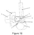
- FIGS. 15 and 16 show a third two-axis control device.
- the device is similar to the device of FIGS. 12-14 , and equivalent features are given the same reference numeral.
- the output shaft of the X-axis actuator is coupled to an L-shaped bracket 10 which is rigidly connected to the pivot block 11 .
- the casing 1 of the X-axis actuator is coupled to the mounting bracket 9 by the drive link 5 .
- the output shaft of the actuator acts as a stator, and the casing acts as a rotor.
- This arrangement has the potential to save some space when roll deflections occur.
- a similar variant of the device of FIGS. 4 and 5 may also be used.
- FIG. 17 show a fourth two-axis control device.
- the device is similar to the device of FIGS. 6-11 , and equivalent features are given the same reference numeral.
- the casing 1 of the X-axis actuator is rigidly connected to the pivot block 11 , and the output shaft is coupled to the mounting bracket 9 by the drive link 5 .
- the output shaft of the actuator acts as a rotor and the casing 1 acts as a stator.
- FIG. 18 show a third one-axis control device.
- the device is similar to the device of FIGS. 1-3 , and equivalent features are given the same reference numeral.
- the actuator is angled downwardly with respect to the line A passing through the pivot axis X and the centre of mass of the stick.
- the device is not mass balanced against horizontal acceleration orthogonal to the pivot axis X, since the centre of mass of the actuator lies in a vertical plane containing the line A the device is mass balanced against vertical acceleration.
- the two-axis devices of FIGS. 6-17 are vertically and horizontally mass balanced about both the X and Y-axes.
- the devices shown in the figures may be used on a vehicle such as a helicopter.
- a vehicle such as a helicopter.
- the one-axis devices shown in FIGS. 1-5 and 18 may be used as the collective lever of a helicopter.
- the devices may be used in a simulator.
Abstract
Description
M=−l 1 m 1 ng+l 2 m 2 ng equation (1)
where:
-
- l1 is the distance between the pivot axis X and the centre of mass of the stick;
- m1 is the mass of the stick (including the
shaft 3 and the handle 4); - l2 is the distance between the pivot axis X and the combined centre of mass of the actuator and force sensor; and
- m2 is the combined mass of the actuator and force sensor.
For mass balance we want M=0 or:
l 1 m 1 ng=l 2 m 2 ng equation (2)
which reduces to:
l 1 m 1 =l 2 m 2 equation (3)
Thus by choosing values which satisfy equation (3), the device is vertically mass balanced about the pivot axis X.
Claims (16)
Priority Applications (3)
| Application Number | Priority Date | Filing Date | Title |
|---|---|---|---|
| PCT/GB2008/002582 WO2009016361A2 (en) | 2007-07-31 | 2008-07-28 | Control device |
| DE112008002046T DE112008002046T5 (en) | 2007-07-31 | 2008-07-28 | control device |
| GB1001509.7A GB2463625B (en) | 2007-07-31 | 2008-07-28 | Control device |
Applications Claiming Priority (2)
| Application Number | Priority Date | Filing Date | Title |
|---|---|---|---|
| GB0714916.4 | 2007-07-31 | ||
| GBGB0714916.4A GB0714916D0 (en) | 2007-07-31 | 2007-07-31 | Control device |
Publications (2)
| Publication Number | Publication Date |
|---|---|
| US20090031840A1 US20090031840A1 (en) | 2009-02-05 |
| US8505406B2 true US8505406B2 (en) | 2013-08-13 |
Family
ID=38529060
Family Applications (1)
| Application Number | Title | Priority Date | Filing Date |
|---|---|---|---|
| US11/844,939 Active 2032-02-12 US8505406B2 (en) | 2007-07-31 | 2007-08-24 | Control device |
Country Status (3)
| Country | Link |
|---|---|
| US (1) | US8505406B2 (en) |
| DE (1) | DE112008002046T5 (en) |
| GB (1) | GB0714916D0 (en) |
Cited By (3)
| Publication number | Priority date | Publication date | Assignee | Title |
|---|---|---|---|---|
| DE202017105886U1 (en) | 2017-09-27 | 2017-11-29 | Spohn & Burkhardt GmbH & Co. KG | switching device |
| US20190066884A1 (en) * | 2017-08-24 | 2019-02-28 | Altec Industries, Inc. | Insulated joystick assembly |
| US11822356B1 (en) | 2023-01-30 | 2023-11-21 | Altec Industries, Inc. | Aerial lift systems and control input apparatuses with high electrical resistance for use with aerial lift systems |
Families Citing this family (2)
| Publication number | Priority date | Publication date | Assignee | Title |
|---|---|---|---|---|
| WO2012044936A1 (en) | 2010-09-30 | 2012-04-05 | Portola Pharmaceuticals, Inc. | Combination therapy with 4-(3-(2h-1,2,3-triazol-2-yl)phenylamino)-2-((1r,2s)-2-aminocyclohexylamino)pyrimidine-5-carboxamide |
| US10118688B2 (en) * | 2015-08-18 | 2018-11-06 | Woodward, Inc. | Inherently balanced control stick |
Citations (30)
| Publication number | Priority date | Publication date | Assignee | Title |
|---|---|---|---|---|
| US2475484A (en) | 1946-05-14 | 1949-07-05 | Nise Dwight Dee De | Method and means for imparting feel back to a manually-movable control element |
| US2678179A (en) | 1949-01-24 | 1954-05-11 | Northrop Aircraft Inc | Hydraulic trim control |
| US2955784A (en) | 1956-02-27 | 1960-10-11 | Northrop Corp | Servo regulated elevator feel system |
| US3795150A (en) * | 1972-12-13 | 1974-03-05 | Us Air Force | System for rapidly positioning gimbaled objects |
| US4069720A (en) | 1976-11-05 | 1978-01-24 | Thor Wayne A | Two axis side controller for aircraft |
| US4071209A (en) | 1976-08-23 | 1978-01-31 | Lockheed Corporation | Vehicle control system incorporating a compensator to stabilize the inherent dynamics thereof |
| US4150803A (en) | 1977-10-05 | 1979-04-24 | Fernandez Carlos P | Two axes controller |
| US4383455A (en) | 1980-10-21 | 1983-05-17 | Kobe Steel, Limited | Arm with gravity-balancing function |
| EP0085518A1 (en) | 1982-01-22 | 1983-08-10 | British Aerospace Public Limited Company | Control apparatus |
| US4531080A (en) * | 1982-06-01 | 1985-07-23 | Saab-Scania Aktiebolag | Controller |
| WO1988009290A1 (en) * | 1987-05-26 | 1988-12-01 | Saab-Scania Aktiebolag | Steering control |
| US4982918A (en) | 1988-01-29 | 1991-01-08 | British Aerospace Public Limited Company | Force sensitive aircraft throttle with feedback |
| US5107080A (en) | 1989-12-01 | 1992-04-21 | Massachusetts Institute Of Technology | Multiple degree of freedom damped hand controls |
| US5265486A (en) * | 1990-09-26 | 1993-11-30 | Ammco Tools Technology Corporation | Portable external drive assembly |
| US5456428A (en) | 1993-07-21 | 1995-10-10 | Honeywell Inc. | Mechanically linked active sidesticks |
| US5473235A (en) | 1993-12-21 | 1995-12-05 | Honeywell Inc. | Moment cell counterbalance for active hand controller |
| JPH0857783A (en) | 1994-08-23 | 1996-03-05 | Kawasaki Heavy Ind Ltd | Operating device |
| US5721566A (en) * | 1995-01-18 | 1998-02-24 | Immersion Human Interface Corp. | Method and apparatus for providing damping force feedback |
| US5816105A (en) * | 1996-07-26 | 1998-10-06 | The United States Of America As Represented By The Administrator Of The National Aeronautics And Space Administration | Three degree of freedom parallel mechanical linkage |
| US5898599A (en) * | 1993-10-01 | 1999-04-27 | Massachusetts Institute Of Technology | Force reflecting haptic interface |
| US5900710A (en) * | 1996-11-22 | 1999-05-04 | Aerospatiale Societe Nationale Industrielle | System for coupling control columns |
| WO2001054587A1 (en) | 2000-01-26 | 2001-08-02 | Massachussets Institute Of Technology | Force feedback user interface for minimally invasive surgical simulator and teleoperator and other similar apparatus |
| US20030030621A1 (en) | 1993-07-16 | 2003-02-13 | Rosenberg Louis B. | Force feeback device including flexure member between actuator and user object |
| US6644600B1 (en) | 2002-04-25 | 2003-11-11 | Rockwell Collins, Inc. | Method and system for providing manipulation restraining forces for a stick controller on an aircraft |
| US6708580B1 (en) | 1999-06-11 | 2004-03-23 | Wittenstein Gmbh & Co. Kg | Device for controlling an apparatus |
| US20060254377A1 (en) | 2003-02-07 | 2006-11-16 | Jorg Henle | Device for controlling a vehicle |
| US20080079381A1 (en) | 2006-10-02 | 2008-04-03 | Honeywell International, Inc. | Motor balanced active user interface assembly |
| US20090229396A1 (en) * | 2006-05-12 | 2009-09-17 | Bae Systems Plc. | Active Stick Apparatus |
| US8066567B2 (en) * | 2006-08-25 | 2011-11-29 | Deere & Company | Joystick with control dampening and detent using electrorheologic cylinder |
| US8087619B2 (en) * | 2008-07-30 | 2012-01-03 | Honeywell International, Inc. | Active control stick assembly including traction drive |
-
2007
- 2007-07-31 GB GBGB0714916.4A patent/GB0714916D0/en not_active Ceased
- 2007-08-24 US US11/844,939 patent/US8505406B2/en active Active
-
2008
- 2008-07-28 DE DE112008002046T patent/DE112008002046T5/en not_active Ceased
Patent Citations (31)
| Publication number | Priority date | Publication date | Assignee | Title |
|---|---|---|---|---|
| US2475484A (en) | 1946-05-14 | 1949-07-05 | Nise Dwight Dee De | Method and means for imparting feel back to a manually-movable control element |
| US2678179A (en) | 1949-01-24 | 1954-05-11 | Northrop Aircraft Inc | Hydraulic trim control |
| US2955784A (en) | 1956-02-27 | 1960-10-11 | Northrop Corp | Servo regulated elevator feel system |
| US3795150A (en) * | 1972-12-13 | 1974-03-05 | Us Air Force | System for rapidly positioning gimbaled objects |
| US4071209A (en) | 1976-08-23 | 1978-01-31 | Lockheed Corporation | Vehicle control system incorporating a compensator to stabilize the inherent dynamics thereof |
| US4069720A (en) | 1976-11-05 | 1978-01-24 | Thor Wayne A | Two axis side controller for aircraft |
| US4150803A (en) | 1977-10-05 | 1979-04-24 | Fernandez Carlos P | Two axes controller |
| US4383455A (en) | 1980-10-21 | 1983-05-17 | Kobe Steel, Limited | Arm with gravity-balancing function |
| EP0085518A1 (en) | 1982-01-22 | 1983-08-10 | British Aerospace Public Limited Company | Control apparatus |
| US4513235A (en) | 1982-01-22 | 1985-04-23 | British Aerospace Public Limited Company | Control apparatus |
| US4531080A (en) * | 1982-06-01 | 1985-07-23 | Saab-Scania Aktiebolag | Controller |
| WO1988009290A1 (en) * | 1987-05-26 | 1988-12-01 | Saab-Scania Aktiebolag | Steering control |
| US4982918A (en) | 1988-01-29 | 1991-01-08 | British Aerospace Public Limited Company | Force sensitive aircraft throttle with feedback |
| US5107080A (en) | 1989-12-01 | 1992-04-21 | Massachusetts Institute Of Technology | Multiple degree of freedom damped hand controls |
| US5265486A (en) * | 1990-09-26 | 1993-11-30 | Ammco Tools Technology Corporation | Portable external drive assembly |
| US20030030621A1 (en) | 1993-07-16 | 2003-02-13 | Rosenberg Louis B. | Force feeback device including flexure member between actuator and user object |
| US5456428A (en) | 1993-07-21 | 1995-10-10 | Honeywell Inc. | Mechanically linked active sidesticks |
| US5898599A (en) * | 1993-10-01 | 1999-04-27 | Massachusetts Institute Of Technology | Force reflecting haptic interface |
| US5473235A (en) | 1993-12-21 | 1995-12-05 | Honeywell Inc. | Moment cell counterbalance for active hand controller |
| JPH0857783A (en) | 1994-08-23 | 1996-03-05 | Kawasaki Heavy Ind Ltd | Operating device |
| US5721566A (en) * | 1995-01-18 | 1998-02-24 | Immersion Human Interface Corp. | Method and apparatus for providing damping force feedback |
| US5816105A (en) * | 1996-07-26 | 1998-10-06 | The United States Of America As Represented By The Administrator Of The National Aeronautics And Space Administration | Three degree of freedom parallel mechanical linkage |
| US5900710A (en) * | 1996-11-22 | 1999-05-04 | Aerospatiale Societe Nationale Industrielle | System for coupling control columns |
| US6708580B1 (en) | 1999-06-11 | 2004-03-23 | Wittenstein Gmbh & Co. Kg | Device for controlling an apparatus |
| WO2001054587A1 (en) | 2000-01-26 | 2001-08-02 | Massachussets Institute Of Technology | Force feedback user interface for minimally invasive surgical simulator and teleoperator and other similar apparatus |
| US6644600B1 (en) | 2002-04-25 | 2003-11-11 | Rockwell Collins, Inc. | Method and system for providing manipulation restraining forces for a stick controller on an aircraft |
| US20060254377A1 (en) | 2003-02-07 | 2006-11-16 | Jorg Henle | Device for controlling a vehicle |
| US20090229396A1 (en) * | 2006-05-12 | 2009-09-17 | Bae Systems Plc. | Active Stick Apparatus |
| US8066567B2 (en) * | 2006-08-25 | 2011-11-29 | Deere & Company | Joystick with control dampening and detent using electrorheologic cylinder |
| US20080079381A1 (en) | 2006-10-02 | 2008-04-03 | Honeywell International, Inc. | Motor balanced active user interface assembly |
| US8087619B2 (en) * | 2008-07-30 | 2012-01-03 | Honeywell International, Inc. | Active control stick assembly including traction drive |
Non-Patent Citations (3)
| Title |
|---|
| International Search Report received in International (PCT) Application No. PCT/GB2008/002582, mailed Feb. 26, 2009. |
| R.L. Hermans, "Design of an Actuated Side Stick Controller for the Simona Research Simulator", Sep. 1999, Technical University Delft, pp. 1-154. |
| Written Opinion of the International Search Authority for Application No. PCT/GB2008/002582, mailed Feb. 26, 2009. |
Cited By (5)
| Publication number | Priority date | Publication date | Assignee | Title |
|---|---|---|---|---|
| US20190066884A1 (en) * | 2017-08-24 | 2019-02-28 | Altec Industries, Inc. | Insulated joystick assembly |
| US10522273B2 (en) * | 2017-08-24 | 2019-12-31 | Altec Industries, Inc. | Insulated joystick assembly |
| DE202017105886U1 (en) | 2017-09-27 | 2017-11-29 | Spohn & Burkhardt GmbH & Co. KG | switching device |
| WO2019063516A1 (en) | 2017-09-27 | 2019-04-04 | Spohn & Burkhardt GmbH & Co. KG | Shifting device |
| US11822356B1 (en) | 2023-01-30 | 2023-11-21 | Altec Industries, Inc. | Aerial lift systems and control input apparatuses with high electrical resistance for use with aerial lift systems |
Also Published As
| Publication number | Publication date |
|---|---|
| GB0714916D0 (en) | 2007-09-12 |
| US20090031840A1 (en) | 2009-02-05 |
| DE112008002046T5 (en) | 2010-08-26 |
Similar Documents
| Publication | Publication Date | Title |
|---|---|---|
| US8505406B2 (en) | Control device | |
| RU2652685C2 (en) | Autopilot system, components and methods | |
| EP1370363B1 (en) | Automatic balance adjusting centrifugal apparatus | |
| AU2020200833A1 (en) | Dispersement system for an unmanned aerial vehicle | |
| EP2586702B1 (en) | Compact two axis gimbal for control stick | |
| JP2758374B2 (en) | Helicopter rotor harmonic controller | |
| US9658639B2 (en) | Inceptor apparatus | |
| AU2002243085A1 (en) | Automatic balance adjusting centrifugal apparatus | |
| AU2016311443B2 (en) | Ganged servo flight control system for an unmanned aerial vehicle | |
| ITMI20001820A1 (en) | METHOD FOR APPARATUS TO DETECT THE PRELOAD IN A LOWER STOP GROUP OF A TILTING ROTOR. | |
| WO2009016361A2 (en) | Control device | |
| US8569988B2 (en) | Elastic rotary actuator, particularly for robotic applications, and method for controlling the same | |
| US20160009386A1 (en) | Low moment force generator devices and methods | |
| US20060254377A1 (en) | Device for controlling a vehicle | |
| JP5411687B2 (en) | Robot control device | |
| JP3168198B2 (en) | Flap drive device and rotor blade | |
| JP2007168561A (en) | Power transmission device for helicopter | |
| CN208820059U (en) | A kind of stabilized platform of carried SAR antenna | |
| JP2665090B2 (en) | Damping device | |
| JP3423090B2 (en) | Operating force detector | |
| JP2021103268A (en) | Support device and imaging apparatus | |
| KR20200132695A (en) | Method and system for reducing vibration on a flexible load | |
| US20230085799A1 (en) | Direct-drive motor Damper | |
| JP4333381B2 (en) | Torque sensor and electric power steering device | |
| US20230179126A1 (en) | Preload control system |
Legal Events
| Date | Code | Title | Description |
|---|---|---|---|
| AS | Assignment |
Owner name: WITTENSTEIN AEROSPACE AND SIMULATION LTD.,UNITED K Free format text: ASSIGNMENT OF ASSIGNORS INTEREST;ASSIGNOR:COWLING, DAVID A.;REEL/FRAME:023907/0567 Effective date: 20100201 Owner name: WITTENSTEIN AEROSPACE AND SIMULATION LTD., UNITED Free format text: ASSIGNMENT OF ASSIGNORS INTEREST;ASSIGNOR:COWLING, DAVID A.;REEL/FRAME:023907/0567 Effective date: 20100201 |
|
| STCF | Information on status: patent grant |
Free format text: PATENTED CASE |
|
| FEPP | Fee payment procedure |
Free format text: PAYOR NUMBER ASSIGNED (ORIGINAL EVENT CODE: ASPN); ENTITY STATUS OF PATENT OWNER: LARGE ENTITY |
|
| AS | Assignment |
Owner name: WITTENSTEIN SE, GERMANY Free format text: NUNC PRO TUNC ASSIGNMENT;ASSIGNOR:WITTENSTEIN AEROSPACE & SIMULATION LIMITED;REEL/FRAME:040587/0249 Effective date: 20161128 |
|
| FPAY | Fee payment |
Year of fee payment: 4 |
|
| MAFP | Maintenance fee payment |
Free format text: PAYMENT OF MAINTENANCE FEE, 8TH YEAR, LARGE ENTITY (ORIGINAL EVENT CODE: M1552); ENTITY STATUS OF PATENT OWNER: LARGE ENTITY Year of fee payment: 8 |