US8491015B2 - Quick-coupling device for pipelines and the like - Google Patents
Quick-coupling device for pipelines and the like Download PDFInfo
- Publication number
- US8491015B2 US8491015B2 US12/804,158 US80415810A US8491015B2 US 8491015 B2 US8491015 B2 US 8491015B2 US 80415810 A US80415810 A US 80415810A US 8491015 B2 US8491015 B2 US 8491015B2
- Authority
- US
- United States
- Prior art keywords
- socket
- locking
- fitting element
- sectors
- central axis
- Prior art date
- Legal status (The legal status is an assumption and is not a legal conclusion. Google has not performed a legal analysis and makes no representation as to the accuracy of the status listed.)
- Active
Links
Images


Classifications
-
- F—MECHANICAL ENGINEERING; LIGHTING; HEATING; WEAPONS; BLASTING
- F16—ENGINEERING ELEMENTS AND UNITS; GENERAL MEASURES FOR PRODUCING AND MAINTAINING EFFECTIVE FUNCTIONING OF MACHINES OR INSTALLATIONS; THERMAL INSULATION IN GENERAL
- F16L—PIPES; JOINTS OR FITTINGS FOR PIPES; SUPPORTS FOR PIPES, CABLES OR PROTECTIVE TUBING; MEANS FOR THERMAL INSULATION IN GENERAL
- F16L37/00—Couplings of the quick-acting type
- F16L37/08—Couplings of the quick-acting type in which the connection between abutting or axially overlapping ends is maintained by locking members
- F16L37/084—Couplings of the quick-acting type in which the connection between abutting or axially overlapping ends is maintained by locking members combined with automatic locking
- F16L37/0842—Couplings of the quick-acting type in which the connection between abutting or axially overlapping ends is maintained by locking members combined with automatic locking by means of a ring which is split into a plurality of component parts which are held in place by means of a resilient ring member
-
- F—MECHANICAL ENGINEERING; LIGHTING; HEATING; WEAPONS; BLASTING
- F16—ENGINEERING ELEMENTS AND UNITS; GENERAL MEASURES FOR PRODUCING AND MAINTAINING EFFECTIVE FUNCTIONING OF MACHINES OR INSTALLATIONS; THERMAL INSULATION IN GENERAL
- F16L—PIPES; JOINTS OR FITTINGS FOR PIPES; SUPPORTS FOR PIPES, CABLES OR PROTECTIVE TUBING; MEANS FOR THERMAL INSULATION IN GENERAL
- F16L37/00—Couplings of the quick-acting type
- F16L37/08—Couplings of the quick-acting type in which the connection between abutting or axially overlapping ends is maintained by locking members
- F16L37/084—Couplings of the quick-acting type in which the connection between abutting or axially overlapping ends is maintained by locking members combined with automatic locking
- F16L37/092—Couplings of the quick-acting type in which the connection between abutting or axially overlapping ends is maintained by locking members combined with automatic locking by means of elements wedged between the pipe and the frusto-conical surface of the body of the connector
- F16L37/0927—Couplings of the quick-acting type in which the connection between abutting or axially overlapping ends is maintained by locking members combined with automatic locking by means of elements wedged between the pipe and the frusto-conical surface of the body of the connector the wedge element being axially displaceable for releasing the coupling
Definitions
- the fitting element 3 passes through the extractor 6 and abuts against the ridges 7 b of the locking sectors 7 . Then the fitting element 3 starts pressing on said ridges 7 b causing passage from the locking position to the release position of the locking element 4 .
- This movement of the extractor 6 causes passage of the locking element 4 from the locking position to the release position, i.e. ridges 7 b of the locking sectors 7 come out of the groove 3 a enabling the fitting element 3 to be pulled out of the socket 2 .
Abstract
A quick-coupling device for circuits circulating fluids under pressure comprising a socket and a fitting element that can be housed in the socket, the socket including an outer body defining at least part of a first channel and comprising an annular cavity opening on the first channel, a substantially annular constraint element at least partly housed in the annular cavity and movable therein, and including a plurality of constraint sectors made up of circular sectors of the constraint element, moved radially and defining a release position wherein the constraint element is retracted into the groove so as to enable the fitting element moving relative to the socket, and a tightening position at which the constraint element secures the fitting element to the socket, an extractor partly housed in the outer body able to move the constraint element from the tightening position to the release position.
Description
The present invention relates to a quick-coupling device for circuits with circulation of fluids under pressure, comprising a fitting element including a second channel, the socket having a central axis, a first channel internal to the socket, and an inlet of the first channel; the first channel being designed to house the fitting element and being brought into fluid communication with the second channel; the socket further comprising an outer body defining at least part of the first channel and comprising an annular cavity opening on the first channel, a substantially annular locking element at least partly housed in the annular cavity and movable within the cavity, and including a plurality of locking sectors consisting of circular sectors of the locking element which can be mutually moved in a radial direction and define a release position at which the locking element is retracted into the annular cavity in such a manner as to enable movement of the fitting element relative to the socket, and a locking position at which the locking element tightly secures the fitting element to the socket. To move the locking element from the locking position to the release position, an extractor, partly housed in the outer body is slided along the central axis relative to the outer body.
This quick-coupling device is a device conceived to enable the simple, safe and immediate, connection and disconnection of pipes belonging to lines for circulation of fluids, possibly under pressure, without using any particular tool.
It is known that the realization of hydraulic lines for fluids under pressure, requires the connection of pipes to tanks, to other pipelines or to other elements using connecting means that achieve fluid passage.
This means can have two components, at least one of which is rigidly connected to one of the two pipes usually through welding or forcing operations, or using pipe-clamping bands. These components are usually provided with threads to mutually join them forming the above-mentioned connection.
However, quick couplings are presently more and more frequently preferred to the above described means, the coupling device being enabling two pipes to be connected and disconnected through simple and quick manual operations. These couplings usually have two base elements: a socket and a fitting element, to be partially inserted inside the socket.
In a first example of a coupling, as described by ISO Standard 8434-1:2007(E), the connection between the fitting element and the socket will be done by a forcing operation. In particular, in the socket the presence of three elements is contemplated: a first base body having a thread, a nut suitable for engagement with the thread and a conical element housed between the two components, inside a suitable cavity formed inside the base body. When the nut is secured to the base body, the conical element is forced between the base body and the fitting element, creating the connection.
Another type of coupling device consists of the so-called “quick couplings”. In these couplings, the fitting element has a groove or an annular ridge on the outer surface, while the socket has an outer casing having a cylindrical cavity to house the fitting element. This cavity also has a hollow circular area housing a plurality of locking elements that can be radially moved due to the presence of an elastic O-ring.
Initially, the fitting element is inserted inside the socket and the locking elements are pushed by the outer surface of the fitting element inside the hollow circular area thus compressing the elastic ring. When the groove or annular ridge is in corresponding of the locking elements, the elastic ring radially pushes the locking elements which are inserted inside the groove achieving a lock between the fitting element and the socket.
Finally, for a quick release of this lock, a sliding body is provided that, when manually pushed by an operator, disengages the locking elements from the groove or annular ridge enabling the separation of the fitting element from the socket.
The above-described known art has some important drawbacks.
In fact, both types of quick couplings presently known are subject to quick deterioration.
In the first example described above, in fact, the engagement and disengagement operations are rather slow, because it is necessary to use of wrenches and the like.
In addition, locked elements by friction can become inseparable due to deposits or deterioration of the coupling areas and, therefore, it becomes impossible to replace those faulty components. In some cases, even by using suitable tools such as wrenches, for example, can be insufficient to release the locked elements
In the second example, a displacement of the locking elements can occur which can bring to the unsteadiness of the quick coupling, leading to the inability of handling high pressures.
A further problem is given by the fact that all known quick couplings are not able to withstand high pressures.
Still another problem is represented by the fact that the two types of actuators are not interchangeable with each other, making impossible to couple the fitting element of one with the socket of the other.
The purpose of the present invention is to conceive a novel quick-coupling device for pipelines and the like capable of substantially obviating the previously-mentioned drawbacks.
Within the scope of this technical task, it is an important aim of the invention to conceive a reliable and durable quick-coupling device. In particular, it is an important aim of the invention to enable the quick-coupling device to be used easily while avoiding the deterioration of the same on prolonged use.
A further fundamental aim of the invention is to obtain a quick-coupling device withstanding high pressures.
Another important aim of the invention is to provide a device that is at least partly usable with the types of couplings presently known, in particular with the coupling in accordance with ISO Standard 8434-1:2007(E).
The novel quick-coupling device for circuits with circulation of fluids under pressure is comprising a fitting element including a second channel, the socket has a central axis, a first channel internal to the socket, and an inlet of the first channel; the first channel is housing the fitting element and being brought into fluid communication with the second channel; the socket is further comprising an outer body defining at least part of the first channel and comprising an annular cavity opening on the first channel, a substantially annular locking element at least partially housed inside the annular cavity and movable within the cavity, and including a plurality of locking sectors consisting of circular sectors of the locking element which are mutually moved in a radial direction from a release position at which the locking element is retracted into the annular cavity in such a manner as to enable free movement of the fitting element relative to the socket, to a locking position at which the locking element tightly secures the fitting element to the socket, an extractor comprising feet, placed between the locking sectors, designed to maintain a minimum distance between the locking sectors and partly housed in the outer body and movable along the central axis relative to the outer body, designed to move the locking element from the locking position to the release position.
The features and advantages of the invention are hereinafter clarified by the detailed description of preferred embodiments of the invention, with reference to the accompanying drawings, in which:
With reference to the drawings, the quick-coupling device for pipelines and the like in accordance with the invention has been generally identified by reference numeral 1.
It is designed to connect, in a quick and easily separable manner, two pipes 20 or, alternatively, one pipe 20 to a device such as a compressor, a tank or other similar device.
The quick coupling 1 comprises a socket 2 having a central axis 2 a and a fitting element 3 to be partly fitted in socket 2 and coupled thereto, preferably being of cylindrical shape. In particular, the fitting element 3 is connected to a pipe 20, while socket 2 is connected to a tank or the like by threading.
The socket 2 and fitting element 3 internally have a first channel 2 d and a second channel 3 b respectively, that are mutually connected for fluid passage, when the socket 2 a and fitting element 3 are fastened to each other. In more detail, the first channel 2 d is adapted to receive the fitting element 3 through an inlet 2 c. The second channel 3 b, on the contrary, comprises an outlet 3 e through which the fluid flows from the fitting element 3 to the socket.
The fitting element 3, shown in FIG. 7 , externally has a coupling surface 3 d that is substantially cylindrical and with an axis substantially coincident with the central axis 2 a, when the fitting element is inserted in the socket 2. Furthermore, this coupling surface 3 d is continuously smooth, i.e. devoid of overhangs or other protruding elements except for a single discontinuity represented by a groove 3 a that is axially symmetric to, and made to a precise distance from the outlet 3 e, as hereinafter better specified. It also has a counter-surface 3 c close to the outlet 3 e and substantially perpendicular to the central axis 2 a.
The socket 2 comprises a locking element 4 that can be moved in a radial direction relative to the central axis 2 a and preferably has an almost circular shape, an outer body 5 defining a first portion of channel 2 c and designed to contain, at least partially, the locking element 4, and an extractor 6 defining a second portion of channel 2 c and adapted to move relative to the outer body 5 in a direction almost parallel to the central axis 2 a.
In greater detail, the outer body 5 has an annular cavity 5 a facing cavity 2 c and designed to house, at least partially, the locking element 4. This annular cavity 5 a extends, as shown in FIG. 3 , in an inclined direction 5 b relative to the central axis 2 a through an angle α in such a manner that the locking element 4, when it moves in a radial direction towards the central axis 2 a, simultaneously moves in the direction of the central axis 2 a towards the inlet 2 c. In particular, angle α is substantially included between 45° and 55° and, preferably, angle α is included between 48° and 52°.
Finally, the outer body 5 has substantially a cylindrical shape and, preferably, with a shaped outer surface so that it can be easily grasped by wrenches or the like. Further, it can be advantageously provided with an outer thread adapted to be connected, by screwing, with a tank or the like.
The locking element 4 also comprises a plurality of locking sectors 7, preferably four, that are at least partly housed inside the annular cavity 5 a. The locking sectors 7 are adapted to be mutually and radially moved. Furthermore, due to the particular geometry of the annular cavity 5 a, the sectors 7, during their radial displacement, advantageously move along an inclined direction 5 b, i.e. they simultaneously move in a radial direction and in a direction parallel to the central axis 2 a toward the inlet 2 c.
Said movement allows two different positions of the locking element 4 to be defined: a release position (FIGS. 10 and 11 ) at which positioning of the locking sectors 7 enables movement of the fitting element 3 relative to the socket 2; and a locking position at which the locking sectors mutually and tightly connect said two components.
In detail, in the locking position, only a portion of the locking element 4 is inside the cavity 5 a, while in the release position, the locking sectors 7 are spaced apart from each other to a greater extend and almost fully laying inside the cavity 5 a. In conclusion, when moving from the release position to the locking position, there is a reduction in the distance between the locking sectors 7 and a consequent reduction in the diameter of the locking element 4, respectively.
In particular, reduction in the distance between the locking sectors 7 is obtained through a spring 8 externally surrounding the locking element 4, as shown in FIGS. 5 a and 5 b. Said spring is disposed within a housing 7 a placed on the outer edge, i.e. the one to a greater distance from the central axis 2 a, of each locking sector 7. In addition, the spring 8 is taking up almost the whole height of the housing 7 a calculated in a direction parallel to the central axis 2 a, so as to ensure a correct positioning of spring 8 and avoid undesired movements of the same. Furthermore, the spring 8 is a metal helical spring preferably made of steel and preferably a spiral spring of which the ends 8 a are rectilinear to avoid them being inserted between two locking sectors 7, when the locking element is in a release position, inhibiting returning to the locking position. In particular, the ends 8 a are tangent to the circumference defined by spring 8 in a rest position (FIG. 2 ).
Finally, each of the locking sectors 7 has a ridge 7 b on its face close to the central axis 2 a, as shown in FIGS. 5 a and 5 b, which in the locking position enters the cavity 3 a locking the fitting element 3 and socket 2 with each other. Upon movement to the release position, the ridge 7 b comes out of the cavity 3 a enabling mutual motion between the fitting element 3 and the socket 2.
The ridge 7 b has an upper conical wall 7 c advantageously extending in an oblique direction 7 d, being inclined through an angle β relative to the central axis 2 a (FIG. 5 a) to allow movement of the locking element 4 from the locking position to the release position, when the fitting element 3 is inserted in socket 2. In particular, the fitting element 3, when inserted inside the socket 2, exerts pressure on the upper conical surface 7 c causing the sectors 7 to enter the annular cavity 5 a and therefore allowing full introduction of the fitting element 3. In particular, angle β is substantially between 45° and 55° and, preferably, it is between 48° and 52°.
In addition, due to the presence of a lower wall 7 g, extraction of the fitting element 3 is facilitated. In fact, the extractor 6 is designed to press on said upper conical wall 7 c so as to move the locking element 4 from the locking position to the release position, thus clearing the groove 3 a and allowing the fitting element 3 to be pulled out.
In addition, the ridge 7 b has a lower surface 7 e almost perpendicular to the central axis 2 a, said surface being adapted to interfere with the counter-surface 3 c of the groove 3 a. Due to this geometry, during the extraction of the fitting element 3, the lower surface 7 e abuts against the counter-surface 3 c preventing the fitting element 3 from being pulled out and aligning it with the axis 2 a. This advantage is also obtained due to the cavity 5 a that, being inclined in the opposite direction relative to the extraction direction of the fitting element 3, prevents an undesired separation of the quick-coupling device 1. Furthermore, the upper surface of the cavity 5 a promotes the entry of the ridge 7 b into the groove 3 a when tightening occurs.
Finally, each sector 7 has, below the lower surface 7 e, and preferably also in correspondence of the ridge 7 b, a cylindrical surface 7 f with an axis substantially coincident with the axis 2 a.
The extractor 6 is designed to slide relative to the outer body 5, in a direction almost parallel to the central axis 2 a and is advantageously provided, at the lower base opposite to the abutment disc 6 b, with teeth 6 a (FIG. 4 ) adapted to be disposed between the locking sectors 7. In particular, when the locking element 4 moves to a locking position, the locking sectors 7 abut against the teeth 6 a determining a minimum distance between said locking sectors 7 and, therefore, a minimum size of the locking element 4. Finally, the number of teeth 6 a is preferably the same as that of the locking sectors 7, i.e. four.
In addition, the lower base of the extractor 6 and the upper base of the locking element 4 are advantageously inclined with respect to the central axis 2 a and parallel to each other, so that movements of the extractor 6 gives rise to a displacement of the locking sectors 7 and vice versa. In greater detail, lowering of extractor 6 causes an increase in the sizes of the locking element 4, i.e. passage of same to a release position (FIG. 1 ), whereas a reduction in the sizes of the locking element 4, i.e. a return to the locked position, causes a raising of extractor 6.
In addition, the extractor 6 is partly housed within the outer body 5 and has an almost cylindrical shape. At the base external to the outer body 5 it has an abutment disc 6 b (FIG. 4 ) designed to push against the upper edge of the external body 5 when the extractor 6 is pressed against said outer body 5.
In order to prevent the extractor 6 from coming out of the outer body 5, the extractor sliding movement is further limited by a retainer 10 shown in FIG. 2 . This retainer 10 is simultaneously housed inside two grooves 10 a formed in the extractor 6 and the outer body 5 and always facing each other, at least partly.
The retainer 10 preferably consists of an open spring ring so as to facilitate insertion into the grooves 10 a. In particular, during the assembling step, it is enlarged and easily inserted into the grooves 10 a of extractor 6. Once it has been positioned, it is allowed to expand so as to adhere to the groove 10 a and, finally, extractor 6 is forcibly inserted into the outer body 2.
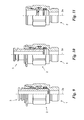
Shown in FIG. 8 is a second possible configuration of the ogive-shaped coupling device according to ISO Standard 8434-1:2007, which is designed to bring into fluid connection two pipes 20 or one pipe 20 connected to a device, such as a tank.
In this example, the coupling device comprises a fitting element 3 and a socket 102 having a central axis 102 a and including a first channel 102 d designed to house the fitting element 3.
In this preferred embodiment, the closing element 106 is designed to be moved along the central axis 102 a and to be rigidly secured to the base body 105 by a threaded coupling, while the locking element 104 has an almost cylindrical shape characterised by a frustoconical end adapted to be inserted inside the cavity 105 a. In particular, after the fitting element 3 has been inserted into the socket 102, the closing element 106, being secured to the base body 105, presses the locking element 104 within the cavity 105 a, which locking element is therefore forced between the fitting element 3 and socket 102 thus carrying out the tightening of the fitting element 3 to socket 102.
The socket 102 preferably has sizes in accordance with ISO Standard 8434-1:2007 or subsequent modifications to said ISO Standard.
The fitting element 3, shown in FIG. 7 , is the one previously described and the given distance of groove 3 a is greater than the distance between the cavity 105 a and outlet 3 e when the fitting element 3 is secured to the socket 102, so that it does not interfere with said tightening action.
Finally, as in the preceding preferred embodiment, groove 3 a has a counter-surface 3 c, i.e. the surface of groove 3 a close to the outlet 3 e, that is preferably substantially perpendicular to the central axis 102 a.
Operation of the quick-coupling device for pipelines and the like described above as regards structure is the following.
Once pipes 20 have been connected to socket 2 and to the fitting element 3, the fitting element 3 is inserted into socket 2 so that said components are secured to each other.
The fitting element 3 passes through the extractor 6 and abuts against the ridges 7 b of the locking sectors 7. Then the fitting element 3 starts pressing on said ridges 7 b causing passage from the locking position to the release position of the locking element 4.
In particular, the locking sectors 7 are moved apart from each other, i.e. the locking element increases its diameter and the locking sectors 7 are almost fully housed within the cavity 5 a (FIG. 10 ) thus enabling the fitting element 3 to complete its fitting. In particular, the fitting element 3 continuing its movement comes into contact with the O-ring 11 deforming it and carrying out a fluid-tight connection.
When the fitting element 3 is inserted, the groove 3 a faces the locking sectors 7 that, being pressed by spring 8, push the ridges 7 b into said groove 3 a securing the fitting element 3 to the socket 2 and bringing the locking element 4 back to its locking position, as shown in FIG. 4 .
In addition, due to their displacement, the locking sectors 7 abut the teeth 6 a causing the locking element 4 to have size close to the minimum size, but not strictly coincident with said minimum size. Consequently, the locking element 4 axially compresses the fitting element 3 centering it on the axis 2 a, in particular by means of the cylindrical surface 7 f.
In addition, before locking, the stop ring 9 is preferably introduced between the abutment disc 6 b and the outer body 5 inhibiting any motion of the extractor 6, so as to avoid an undesirable disengagement of the quick-coupling device 1.
When the quick-coupling device 1 needs to be disengaged, i.e. the fitting element 3 is needs to be separated from socket 2, the stop ring 9 is removed from its housing and the extractor is lowered bringing the abutment disc 6 b almost in contact with the outer body 5.
This movement of the extractor 6 causes passage of the locking element 4 from the locking position to the release position, i.e. ridges 7 b of the locking sectors 7 come out of the groove 3 a enabling the fitting element 3 to be pulled out of the socket 2.
Once the fitting element 3 has been pulled out, the locking element 4, due to action of the spring 8, goes back to the locking position with the locking sectors 7 being adjacent to teeth 6 a, as shown in FIG. 11 .
The invention enables important advantages to be achieved.
A first advantage of the quick-coupling device 1 is represented by the high reliability and duration.
In fact, due to the presence of teeth 6 a, the locking sectors 7 going back to the locking position are not submitted to dangerous mutual displacements and their mutual distance is almost unchanged and therefore the tightening strength between fitting element 3 and socket 2 is not diminished.
Another advantage is represented by the quick-coupling device ability that is ensured by the particular geometry of the lower surface 7 e and the counter-wall 3 c. The quick-coupling device 1 is therefore able to withstand pressures up to 350 bars.
Still another advantage is provided by the metal spring 8 adapted to have a longer duration and greater spring force, also ensured by the number and shape of the sectors 7.
A further important advantage is represented by the possibility of using the fitting element 3 also with ogive-shaped coupling devices of the type ISO Standard 8434-1:2007 presently known. In fact, the particular height where the groove 3 a is formed, does not prevent the known quick-coupling devices, as above described, to be connected and fastened.
The invention is susceptible of variations falling within the inventive idea.
All of the details can be replaced by equivalent elements and the materials, shapes and sizes can be of any nature and magnitude.
Claims (12)
1. A socket (2) for a quick-coupling device (1) for circuits carrying fluids under pressure, said quick-coupling device (1) comprising a fitting element (3) including a second channel (3 b), said socket (2) has a central axis (2 a), a first channel (2 d) internal to said socket (2), and an inlet (2 c) of said first channel (2 d); said first channel (2 d) being designed to house securely said fitting element (3) and being brought into fluid communication with said second channel (3 b); said socket (2) comprises an outer body (5) defining at least part of said first channel (2 d) and comprising an annular cavity (5 a) opening on said first channel (2 d), a substantially annular locking element (4) at least partially housed inside said annular cavity (5 a) and movable within said cavity, said locking element (4) comprises a plurality of locking sectors (7) consisting of sectors of a circular ring which are designed to be mutually moved in a radial direction from a release position at which said locking element (4) is retracted inside said annular cavity (5 a) in such a manner as to enable movement of said fitting element (3) relative to said socket (2), to a locking position at which said locking element (4) tightly secures said fitting element (3) to said socket (2), an extractor (6) comprising a plurality of angled teeth (6 a) each of them inserted between each pair of locking sectors (7), used to maintain a minimum distance between each pair of locking sectors (7); said extractor (6) is partly housed inside said outer body (5) and movable along said central axis (2 a) relative to said outer body (5), to displace said locking element (4) from said locking position to said release position; said socket (2) further comprising a spring (8) which positions said locking element (4) to said release position in the absence of counter-forces.
2. A socket (2) as claimed in claim 1 , wherein said spring (8) is a helical metal spring and has rectilinear ends (8 a) to prevent unwanted insertion inside the gaps between each pair of locking sectors (7).
3. A socket (2) as claimed in claim 1 , wherein each of said locking sectors (7) has a housing (7 a) to contain, at least partially, said spring (8).
4. A socket (2) as claimed in claim 1 , wherein said annular cavity (5 a) extends in an inclined direction (5 b) relative to said central axis (2 a) in such a manner that, when said locking sectors (7) move in a radial direction towards said central axis (2 a), said locking sectors (7) move simultaneously in the direction of said central axis (2 a) towards said inlet (2 c).
5. A socket (2) as claimed in claim 1 , wherein said locking element (4), when said socket (2) houses said fitting element (3), is able to align said fitting element (3) to said central axis (2 a).
6. A socket (2) as claimed in claim 1 , wherein said extractor (6) has an abutment disc (6 b) to abut on said outer body (5), and wherein said socket (2) comprises a stop ring (9) to be inserted between said abutment disc (6 b) and said outer body (5) thereby inhibiting the motion of said extractor (6) relative to said outer body (5).
7. A socket (2) as claimed in claim 1 , wherein each of the locking sectors (7) comprises a protuberance (7 b) to penetrate inside a groove (3 a) to lock securely said fitting element (3) into said socket (2), when said locking element (4) is in said locking position.
8. A socket (2) as claimed in claim 7 , wherein said protuberance (7 b) comprises an upper conical wall (7 c) extending in an oblique direction (7 d) relative to said central axis (2 a) and designed to allow movement of said locking element (4) from said locking position to said release position, when said fitting element (3) is inserted into said socket (2).
9. A socket (2) as claimed in claim 8 , wherein said locking element (4) is moved from said locking position to said release position whenever said extractor (6) exerts sufficient pressure on said upper conical wall (7 c), causing said protuberances (7 b) to be dislodged from said groove (3 a) of the fitting element (3).
10. A socket (2) as claimed in claim 7 , wherein said protuberances (7 b) have a lower surface (7 e) that is substantially perpendicular to said central axis (2 a).
11. A quick-coupling device (1) for circuits having circulation of fluids under pressure, comprising a socket (2), as claimed in claim 1 , and a fitting element (3) and wherein said fitting element (3) has a groove (3 a) designed to receive a plurality of protuberances (7 b).
12. A quick-coupling device (1) as claimed in claim 11 , wherein said groove (3 a) has a counter-surface (3 c) which is substantially perpendicular to said central axis (2 a) and is designed to interfere with said protuberances (7 b).
Applications Claiming Priority (3)
| Application Number | Priority Date | Filing Date | Title |
|---|---|---|---|
| ITMI2010A000772 | 2010-05-04 | ||
| IT000772A ITMI20100772A1 (en) | 2010-05-04 | 2010-05-04 | QUICK CONNECTION FOR PIPES AND THE LIKE |
| ITMI2010A0772 | 2010-05-04 |
Publications (2)
| Publication Number | Publication Date |
|---|---|
| US20110272935A1 US20110272935A1 (en) | 2011-11-10 |
| US8491015B2 true US8491015B2 (en) | 2013-07-23 |
Family
ID=43216598
Family Applications (1)
| Application Number | Title | Priority Date | Filing Date |
|---|---|---|---|
| US12/804,158 Active US8491015B2 (en) | 2010-05-04 | 2010-07-15 | Quick-coupling device for pipelines and the like |
Country Status (4)
| Country | Link |
|---|---|
| US (1) | US8491015B2 (en) |
| EP (1) | EP2385289B1 (en) |
| ES (1) | ES2575606T3 (en) |
| IT (1) | ITMI20100772A1 (en) |
Cited By (2)
| Publication number | Priority date | Publication date | Assignee | Title |
|---|---|---|---|---|
| US20130207381A1 (en) * | 2010-07-05 | 2013-08-15 | Australasian Steel Products Pty Ltd | Fluid coupling |
| US11137099B2 (en) * | 2019-03-28 | 2021-10-05 | C.MATIC S.p.A. | Quick coupling for pipes and the like |
Families Citing this family (2)
| Publication number | Priority date | Publication date | Assignee | Title |
|---|---|---|---|---|
| US9360143B2 (en) | 2012-08-14 | 2016-06-07 | Mueller Industries, Inc. | Quick-connect assembly for a fluid valve |
| KR102270408B1 (en) * | 2019-02-27 | 2021-06-29 | 주식회사 피봇기술 | pivoting prop style pipe connecting system |
Citations (8)
| Publication number | Priority date | Publication date | Assignee | Title |
|---|---|---|---|---|
| US5005877A (en) * | 1988-12-16 | 1991-04-09 | Parker Hannifin Corporation | Quick connect/disconnect fluid coupling |
| US5580100A (en) * | 1994-02-25 | 1996-12-03 | Usui Kokusai Sangyo Kaisha Ltd. | Connecting joint for plastic tube |
| US5934709A (en) * | 1994-03-11 | 1999-08-10 | Australasian Steel Products Pty Ltd. | Fluid couplings |
| US6186557B1 (en) * | 1998-02-24 | 2001-02-13 | Johannes Schafer Vorm. Stettiner Schrauben Werke Gmbh & Co. Kg | Pipe connection and combination of a connection and a detaching tool |
| US20020000721A1 (en) * | 2000-06-08 | 2002-01-03 | Hitachi Metals, Ltd. | Sleeve-type pipe joint |
| US20030001386A1 (en) * | 2001-06-29 | 2003-01-02 | Cresswell William L. | Quick connect / disconnect coupling |
| US7431346B2 (en) * | 2005-11-21 | 2008-10-07 | Campbell Hausfeld/Scott Fetzer Company | Quick connect coupling |
| US7832774B2 (en) * | 2002-06-14 | 2010-11-16 | Eaton Corporation | Coupling assembly |
-
2010
- 2010-05-04 IT IT000772A patent/ITMI20100772A1/en unknown
- 2010-07-08 EP EP10007067.1A patent/EP2385289B1/en active Active
- 2010-07-08 ES ES10007067.1T patent/ES2575606T3/en active Active
- 2010-07-15 US US12/804,158 patent/US8491015B2/en active Active
Patent Citations (8)
| Publication number | Priority date | Publication date | Assignee | Title |
|---|---|---|---|---|
| US5005877A (en) * | 1988-12-16 | 1991-04-09 | Parker Hannifin Corporation | Quick connect/disconnect fluid coupling |
| US5580100A (en) * | 1994-02-25 | 1996-12-03 | Usui Kokusai Sangyo Kaisha Ltd. | Connecting joint for plastic tube |
| US5934709A (en) * | 1994-03-11 | 1999-08-10 | Australasian Steel Products Pty Ltd. | Fluid couplings |
| US6186557B1 (en) * | 1998-02-24 | 2001-02-13 | Johannes Schafer Vorm. Stettiner Schrauben Werke Gmbh & Co. Kg | Pipe connection and combination of a connection and a detaching tool |
| US20020000721A1 (en) * | 2000-06-08 | 2002-01-03 | Hitachi Metals, Ltd. | Sleeve-type pipe joint |
| US20030001386A1 (en) * | 2001-06-29 | 2003-01-02 | Cresswell William L. | Quick connect / disconnect coupling |
| US7832774B2 (en) * | 2002-06-14 | 2010-11-16 | Eaton Corporation | Coupling assembly |
| US7431346B2 (en) * | 2005-11-21 | 2008-10-07 | Campbell Hausfeld/Scott Fetzer Company | Quick connect coupling |
Cited By (2)
| Publication number | Priority date | Publication date | Assignee | Title |
|---|---|---|---|---|
| US20130207381A1 (en) * | 2010-07-05 | 2013-08-15 | Australasian Steel Products Pty Ltd | Fluid coupling |
| US11137099B2 (en) * | 2019-03-28 | 2021-10-05 | C.MATIC S.p.A. | Quick coupling for pipes and the like |
Also Published As
| Publication number | Publication date |
|---|---|
| EP2385289B1 (en) | 2016-04-27 |
| EP2385289A1 (en) | 2011-11-09 |
| ES2575606T3 (en) | 2016-06-29 |
| ITMI20100772A1 (en) | 2011-11-05 |
| US20110272935A1 (en) | 2011-11-10 |
Similar Documents
| Publication | Publication Date | Title |
|---|---|---|
| CA2585076C (en) | Quick connect coupling | |
| US5406980A (en) | Deep drawn quick connect coupling | |
| US4335908A (en) | Push-in tube connector | |
| US8491015B2 (en) | Quick-coupling device for pipelines and the like | |
| KR100877545B1 (en) | Quick connect coupling | |
| US20240093816A1 (en) | System for conduit squeeze retainer | |
| US20110204624A1 (en) | Universal connection socket | |
| CA2379222C (en) | Universal safety coupler | |
| US20120200080A1 (en) | Variable Curvature Clip For Quick Connect Coupling | |
| US8746751B2 (en) | Quick connect coupling systems with insert | |
| US20230003322A1 (en) | Tubular connector | |
| CN111750191B (en) | Quick coupling for pipes | |
| US20160169432A1 (en) | Hydraulic cylinder joint and hydraulic cylinder pipe including same | |
| US20200173819A1 (en) | Quick connect sensor assembly | |
| NO344166B1 (en) | Pipe quick connector | |
| EP3301339A1 (en) | Press-fitting connector for corrugated pipes and press-fitting tool for its application | |
| EP3462070B1 (en) | Releasable fitting | |
| US20060082151A1 (en) | Coupling assembly with connection indicator | |
| EP3405644B1 (en) | Pipe coupling | |
| TWM648985U (en) | Quick joint structure | |
| JP2009138869A (en) | Pipe joint connection component and piping structure | |
| US10400930B2 (en) | Coupling | |
| EP1479962A1 (en) | Quick coupling device | |
| CN103097795A (en) | Sanitary clamp coupler with radial seal | |
| JP6021381B2 (en) | Pipe end receiving socket and method of inserting and connecting cylindrical pipe to socket |
Legal Events
| Date | Code | Title | Description |
|---|---|---|---|
| AS | Assignment |
Owner name: C.MATIC S.R.L., ITALY Free format text: ASSIGNMENT OF ASSIGNORS INTEREST;ASSIGNOR:CONFALONIERI, ORAZIO;REEL/FRAME:024834/0873 Effective date: 20100713 |
|
| STCF | Information on status: patent grant |
Free format text: PATENTED CASE |
|
| FPAY | Fee payment |
Year of fee payment: 4 |
|
| MAFP | Maintenance fee payment |
Free format text: PAYMENT OF MAINTENANCE FEE, 8TH YEAR, MICRO ENTITY (ORIGINAL EVENT CODE: M3552); ENTITY STATUS OF PATENT OWNER: MICROENTITY Year of fee payment: 8 |