US8490510B2 - Robot arm mechanism and robot using the same - Google Patents
Robot arm mechanism and robot using the same Download PDFInfo
- Publication number
- US8490510B2 US8490510B2 US13/088,518 US201113088518A US8490510B2 US 8490510 B2 US8490510 B2 US 8490510B2 US 201113088518 A US201113088518 A US 201113088518A US 8490510 B2 US8490510 B2 US 8490510B2
- Authority
- US
- United States
- Prior art keywords
- shell
- air
- motor
- shaft
- output shaft
- Prior art date
- Legal status (The legal status is an assumption and is not a legal conclusion. Google has not performed a legal analysis and makes no representation as to the accuracy of the status listed.)
- Expired - Fee Related, expires
Links
Images


Classifications
-
- B—PERFORMING OPERATIONS; TRANSPORTING
- B25—HAND TOOLS; PORTABLE POWER-DRIVEN TOOLS; MANIPULATORS
- B25J—MANIPULATORS; CHAMBERS PROVIDED WITH MANIPULATION DEVICES
- B25J19/00—Accessories fitted to manipulators, e.g. for monitoring, for viewing; Safety devices combined with or specially adapted for use in connection with manipulators
- B25J19/0054—Cooling means
-
- Y—GENERAL TAGGING OF NEW TECHNOLOGICAL DEVELOPMENTS; GENERAL TAGGING OF CROSS-SECTIONAL TECHNOLOGIES SPANNING OVER SEVERAL SECTIONS OF THE IPC; TECHNICAL SUBJECTS COVERED BY FORMER USPC CROSS-REFERENCE ART COLLECTIONS [XRACs] AND DIGESTS
- Y10—TECHNICAL SUBJECTS COVERED BY FORMER USPC
- Y10T—TECHNICAL SUBJECTS COVERED BY FORMER US CLASSIFICATION
- Y10T74/00—Machine element or mechanism
- Y10T74/20—Control lever and linkage systems
- Y10T74/20207—Multiple controlling elements for single controlled element
- Y10T74/20305—Robotic arm
- Y10T74/20311—Robotic arm including power cable or connector
-
- Y—GENERAL TAGGING OF NEW TECHNOLOGICAL DEVELOPMENTS; GENERAL TAGGING OF CROSS-SECTIONAL TECHNOLOGIES SPANNING OVER SEVERAL SECTIONS OF THE IPC; TECHNICAL SUBJECTS COVERED BY FORMER USPC CROSS-REFERENCE ART COLLECTIONS [XRACs] AND DIGESTS
- Y10—TECHNICAL SUBJECTS COVERED BY FORMER USPC
- Y10T—TECHNICAL SUBJECTS COVERED BY FORMER US CLASSIFICATION
- Y10T74/00—Machine element or mechanism
- Y10T74/20—Control lever and linkage systems
- Y10T74/20207—Multiple controlling elements for single controlled element
- Y10T74/20305—Robotic arm
- Y10T74/20317—Robotic arm including electric motor
Definitions
- This disclosure relates to robotics, and particularly, to a robot arm mechanism and a robot using the same.
- a commonly used robot generally includes a plurality of rotary shafts and a plurality of motors assembled with the robot for driving the rotary shafts to rotate.
- the motors generate much heat thereby sharply increasing the internal temperature within the robot. This may cause the motor encoder of the robot to send an alarm or even cause the robot to stop working. Therefore, cooling fans are assembled within the robot to dissipate and carry the heat to outside of the robot.
- the existing cooling fans occupy a relatively large amount of space within the robot, which means that the inner structure of the robot is made larger.
- FIG. 1 shows an assembled isometric view of an embodiment of a robot, wherein, the robot includes a robot arm mechanism, an air source, and an air evacuating equipment.
- FIG. 2 shows a partially exploded isometric view of the robot arm mechanism of FIG. 1 .
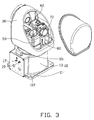
- FIG. 3 is similar to FIG. 2 , but viewed from another aspect.
- FIG. 4 shows an exploded isometric view of the robot arm mechanism of FIG. 1 .
- FIG. 5 is similar to FIG. 4 , but viewed from another aspect.
- an embodiment of a robot 100 includes a robot arm mechanism 200 , an air source 920 and an air evacuating equipment 940 .
- the robot arm mechanism 200 includes a first shaft assembly 10 , a second shaft assembly 30 rotatably assembled with the first shaft assembly 10 , a first motor 50 , a second motor 60 , an air tubing assembly 70 and a support member 80 .
- the first and second motors 50 , 60 are selectively assembled within the first shaft assembly 10 and/or the second shaft assembly 30 . In the illustrated embodiment, the first and second motors 50 , 60 are both assembled within the second shaft assembly 30 .
- the air tubing assembly 70 is assembled within the first shaft assembly 10 and/or the second shaft assembly 30 , and surrounds the first and second motors 50 , 60 , and further connects with the air source 920 and the air evacuating equipment 940 for cooling down the inner temperature of the robot 100 .
- the first shaft assembly 10 includes a base 11 , a first shell 13 , a first output shaft 15 , an air inlet port 17 and an air evacuating port 19 .
- the base 11 is a substantially rectangular board, and includes four mounting holes 112 respectively defined through four corners of the base 11 .
- the first shell 13 is a substantially hollow cylinder extending from and covering the base 11 .
- the first shell 13 defines a connecting shaft hole 131 through a distal end positioned away from and substantially perpendicular to the base 11 .
- the first output shaft 15 is rotatably assembled within the connecting shaft hole 131 of the first shell 13 .
- the first output shaft 15 defines a first wire hole 151 axially.
- the air inlet port 17 is disposed on the first shell 13 with one end connected to the air source 920 , and the other end connected to the air tubing assembly 70 .
- the air evacuating port 19 is also disposed on the first shell 13 and positioned adjacent to the air inlet port 17 .
- One end of the air evacuating port 19 communicates with the inner space of the first shell 13 .
- the other end of the air evacuating port 19 is connected to the air evacuating equipment 940 for exhausting the air within the robot 100 .
- the second shaft assembly 30 includes a second shell 32 , a connecting portion 34 formed on the second shell 32 , a second output shaft 36 , a first fixing member 37 and a second fixing member 38 .
- the second shell 32 is also substantially hollow cylindrical and includes a main body 322 and a cover 324 .
- the main body 322 defines an opening 3221 at one end.
- the cover 324 is detachably assembled to the main body 322 for covering the opening 3221 .
- the connecting portion 34 is formed at one side of the main body 322 and configured for fixing with the first output shaft 15 of the first shaft assembly 10 .
- the connecting portion 34 defines a second wire hole 342 corresponding to the first wire hole 151 of the first output shaft 15 .
- the second output shaft 36 is rotatably assembled to the other end of the main body 322 of the second shell 32 and is positioned away from the opening 3221 .
- the second output shaft 36 is perpendicular to the first output shaft 15 .
- the first fixing member 37 and the second fixing member 38 are both formed and received within the second shell 32 .
- the first fixing member 37 connects with the connecting portion 34 and is positioned adjacent to the first wire hole 151 of the first output shaft 15 .
- the first fixing member 37 defines a first shaft hole 372 perpendicular to the second output shaft 36 .
- the second fixing member 38 is positioned at a same end with the second output shaft 36 and defines a second shaft hole 382 parallel to the second output shaft 36 .
- the first motor 50 is assembled to the first fixing member 37 and received within the second shell 32 .
- a rotary shaft (not shown) of the first motor 50 passes through the first shaft hole 372 of the first fixing member 37 and is connected to the first output shaft 15 of the first shaft assembly 10 by a transmission assembly (not shown), thereby driving the first output shaft 15 to rotate relative to the first shell 13 .
- the second motor 60 is assembled to the second fixing member 38 and received within the second shell 32 .
- the second motor 60 includes a rotary shaft 62 .
- the rotary shaft 62 of the second motor 60 passes through the second shaft hole 382 of the second fixing member 38 and is connected to the second output shaft 36 of the second shaft assembly 30 with a transmission assembly (not shown), thereby driving the second output shaft 36 to rotate relative to the second shell 32 .
- the air tubing assembly 70 includes an air intake pipe 72 and an air vent 74 .
- One end of the air intake pipe 72 is connected with the air inlet port 17 , the other end of the air intake pipe 72 passes through the second wire hole 342 of the connecting portion 34 and the first wire hole 151 of the first output shaft 15 , then enters into the second shell 32 , and finally connects with the air vent 74 .
- the air vent 74 defines a plurality of air blow holes 742 selectively facing toward the first motor 50 and/or the second motor 60 .
- the plurality of air blow holes 742 of the air vent 74 are configured for blowing air to the first and second motors 50 , 60 and cooling down the inner temperature of the robot 100 .
- the air vent 74 could include a plurality of air tubings communicating with each other and surrounding the first and second motors 50 , 60 .
- the air vent 74 includes a first circulating loop 744 surrounding the first motor 50 , a second circulating loop 746 surrounding the second motor 60 , a third circulating loop 748 arranged within the second shell 32 , and a plurality of connecting pipes 749 .
- the first, second and third circulating loops 744 , 746 , 748 are connected to each other with the plurality of connecting pipes 749 .
- the support member 80 is assembled within the second shell 32 for supporting the air tubing assembly 70 .
- Each support member 80 includes a fixing portion 82 and a support portion 84 .
- the fixing portion 82 is a substantially rectangular board, where one end of the fixing portion 82 is bent to form a fixing end 822 and fixed to the second shell 32 .
- the support portion 84 is substantially arc-shaped and formed at the opposite other end of the fixing portion 82 . Two ends of the support portion 84 are connected to the corresponding air vent 74 .
- the air vent 74 is made of a rigid material such as hard rubber, hard plastics, or other similar hard materials.
- the air inlet port 17 of the first shaft assembly 10 is connected to the air source 920 , thus, the outside cooler air can be drawn within into the robot 100 by the air intake pipe 72 and the air vent 74 .
- the air passing through the first, second and third circulating loops 744 , 746 , 748 is directly and continuously blowing towards the first motor 50 , the second motor 60 and the second shell 32 , thereby cooling down the inner temperature of the robot 100 .
- the hot air within the robot 100 can be evacuated to the outside of the robot 100 from the air evacuating port 19 with the air evacuating equipment 940 .
- first and second motors 50 , 60 are not limited to be assembled within the second shell 32 of the second shaft assembly 30 .
- the first and second motors 50 , 60 can also be assembled within the first shell 13 of the first shaft assembly 10 , and the air vent 40 can be arranged within the first shell 13 to cool down the first and second motors 50 , 60 .
Abstract
Description
Claims (16)
Applications Claiming Priority (3)
| Application Number | Priority Date | Filing Date | Title |
|---|---|---|---|
| CN201010266824 | 2010-08-30 | ||
| CN201010266824.5 | 2010-08-30 | ||
| CN201010266824.5A CN102380877B (en) | 2010-08-30 | 2010-08-30 | Robot and arm part thereof |
Publications (2)
| Publication Number | Publication Date |
|---|---|
| US20120048051A1 US20120048051A1 (en) | 2012-03-01 |
| US8490510B2 true US8490510B2 (en) | 2013-07-23 |
Family
ID=45695371
Family Applications (1)
| Application Number | Title | Priority Date | Filing Date |
|---|---|---|---|
| US13/088,518 Expired - Fee Related US8490510B2 (en) | 2010-08-30 | 2011-04-18 | Robot arm mechanism and robot using the same |
Country Status (2)
| Country | Link |
|---|---|
| US (1) | US8490510B2 (en) |
| CN (1) | CN102380877B (en) |
Cited By (1)
| Publication number | Priority date | Publication date | Assignee | Title |
|---|---|---|---|---|
| US9806457B2 (en) * | 2015-04-09 | 2017-10-31 | Fanuc Corporation | Articulated robot with connection member for connecting wire body arranged on arm |
Families Citing this family (12)
| Publication number | Priority date | Publication date | Assignee | Title |
|---|---|---|---|---|
| JP6874535B2 (en) * | 2016-08-31 | 2021-05-19 | セイコーエプソン株式会社 | robot |
| USD807936S1 (en) * | 2017-04-27 | 2018-01-16 | Engineering Services Inc. | Robotic joint |
| US10022861B1 (en) | 2017-04-27 | 2018-07-17 | Engineering Services Inc. | Two joint module and arm using same |
| JP2019048360A (en) * | 2017-09-12 | 2019-03-28 | セイコーエプソン株式会社 | Robot and robot system |
| JP7027775B2 (en) * | 2017-09-29 | 2022-03-02 | セイコーエプソン株式会社 | robot |
| USD898090S1 (en) * | 2018-05-18 | 2020-10-06 | Universal Robots A/S | Toothed connection flange for a robot joint |
| USD895705S1 (en) * | 2018-05-18 | 2020-09-08 | Universal Robots A/S | Robot joint having an input flange, an output flange, and a top lid |
| CN110962158B (en) * | 2018-09-28 | 2021-09-17 | 台达电子工业股份有限公司 | Heat dissipation system of robot |
| USD891494S1 (en) * | 2019-03-15 | 2020-07-28 | Misty Robotics, Inc. | Socket for a Robotic arm |
| USD890829S1 (en) * | 2019-03-15 | 2020-07-21 | Misty Robotics, Inc. | Flange for a robotic arm |
| DE102020103058B3 (en) * | 2020-02-06 | 2021-07-08 | Beckhoff Automation Gmbh | Arm module, robotic arm and industrial robot |
| CN111791263B (en) * | 2020-06-24 | 2021-09-17 | 深圳市优必选科技股份有限公司 | Steering wheel module and arm |
Citations (17)
| Publication number | Priority date | Publication date | Assignee | Title |
|---|---|---|---|---|
| US3602746A (en) * | 1970-03-23 | 1971-08-31 | John C St Clair | Motor-generator with hollow plastic rotor rotating in high pressure chamber |
| JPH07246587A (en) | 1994-03-11 | 1995-09-26 | Yaskawa Electric Corp | Cooling structure of articulated industrial robot |
| US6222289B1 (en) * | 1995-06-05 | 2001-04-24 | Tempco Electric Heater Corp. | Electric motor housings with integrated heat removal facilities |
| US6298684B1 (en) * | 1999-07-26 | 2001-10-09 | Jel Corporation | Substrate transfer robot |
| US6408710B1 (en) * | 1995-02-24 | 2002-06-25 | Abb Ab | Industrial robot having convection cooled frequency converters |
| US6459178B1 (en) * | 1998-12-30 | 2002-10-01 | Abb Research Ltd. | Forced-convection heat exchanger for a rotary electrical machine |
| US6633097B2 (en) * | 2001-09-10 | 2003-10-14 | General Electric Company | Mechanical joining for water-cooled motor frame |
| US6811124B2 (en) * | 2002-06-05 | 2004-11-02 | Kuka Roboter Gmbh | Device for guiding a hose |
| US6819016B2 (en) * | 2002-07-18 | 2004-11-16 | Tm4 Inc. | Liquid cooling arrangement for electric machines |
| US7122923B2 (en) * | 2003-07-10 | 2006-10-17 | Magnetic Applications Inc. | Compact high power alternator |
| US7202442B2 (en) * | 2004-02-27 | 2007-04-10 | Daihen Corporation | Cable arrangement for robot arm, and industrial robot utilizing the same |
| CN101096100A (en) | 2006-06-29 | 2008-01-02 | 日本电产三协株式会社 | Robot for industry |
| US7464622B2 (en) * | 2003-12-10 | 2008-12-16 | Kuka Roboter Gmbh | Manipulator such as in industrial robot and method for influencing an ambient condition therein |
| US7476992B2 (en) * | 2005-05-17 | 2009-01-13 | Parker-Hannifin Corporation | Air-cooled electric motor |
| US7551981B2 (en) * | 2005-11-10 | 2009-06-23 | Hugo Salamanca | Robot system and method for inspecting and repairing casts in smelting processes |
| US7622001B2 (en) * | 2004-09-28 | 2009-11-24 | Kawasaki Jukogyo Kabushiki Kaisha | Robot |
| US8336420B2 (en) * | 2010-06-02 | 2012-12-25 | Disney Enterprises, Inc. | Three-axis robotic joint using four-bar linkages to drive differential side gears |
Family Cites Families (5)
| Publication number | Priority date | Publication date | Assignee | Title |
|---|---|---|---|---|
| JPH08168990A (en) * | 1994-12-14 | 1996-07-02 | Fanuc Ltd | Cooling device for motor of industrial robot |
| FR2745437A1 (en) * | 1996-02-28 | 1997-08-29 | Leroy Somer Moteurs | COOLING CASE FOR AN ELECTRICAL APPARATUS, A ROTATING MACHINE COMPRISING SUCH A CARTER, AND THE METHOD OF MANUFACTURING SUCH A CARTER |
| JP2001025211A (en) * | 1999-07-05 | 2001-01-26 | Nissan Motor Co Ltd | Motor and manufacture thereof |
| DE10013721A1 (en) * | 2000-03-21 | 2001-09-27 | Guenther Battenberg | Method and device for air conditioning robots |
| SE0202211L (en) * | 2002-07-11 | 2004-01-12 | Abb Ab | Device of industrial robot |
-
2010
- 2010-08-30 CN CN201010266824.5A patent/CN102380877B/en active Active
-
2011
- 2011-04-18 US US13/088,518 patent/US8490510B2/en not_active Expired - Fee Related
Patent Citations (18)
| Publication number | Priority date | Publication date | Assignee | Title |
|---|---|---|---|---|
| US3602746A (en) * | 1970-03-23 | 1971-08-31 | John C St Clair | Motor-generator with hollow plastic rotor rotating in high pressure chamber |
| JPH07246587A (en) | 1994-03-11 | 1995-09-26 | Yaskawa Electric Corp | Cooling structure of articulated industrial robot |
| US6408710B1 (en) * | 1995-02-24 | 2002-06-25 | Abb Ab | Industrial robot having convection cooled frequency converters |
| US6222289B1 (en) * | 1995-06-05 | 2001-04-24 | Tempco Electric Heater Corp. | Electric motor housings with integrated heat removal facilities |
| US6459178B1 (en) * | 1998-12-30 | 2002-10-01 | Abb Research Ltd. | Forced-convection heat exchanger for a rotary electrical machine |
| US6298684B1 (en) * | 1999-07-26 | 2001-10-09 | Jel Corporation | Substrate transfer robot |
| US6633097B2 (en) * | 2001-09-10 | 2003-10-14 | General Electric Company | Mechanical joining for water-cooled motor frame |
| US6811124B2 (en) * | 2002-06-05 | 2004-11-02 | Kuka Roboter Gmbh | Device for guiding a hose |
| US6819016B2 (en) * | 2002-07-18 | 2004-11-16 | Tm4 Inc. | Liquid cooling arrangement for electric machines |
| US7122923B2 (en) * | 2003-07-10 | 2006-10-17 | Magnetic Applications Inc. | Compact high power alternator |
| US7768166B2 (en) * | 2003-07-10 | 2010-08-03 | Magnetic Applications, Inc. | Compact high power alternator |
| US7464622B2 (en) * | 2003-12-10 | 2008-12-16 | Kuka Roboter Gmbh | Manipulator such as in industrial robot and method for influencing an ambient condition therein |
| US7202442B2 (en) * | 2004-02-27 | 2007-04-10 | Daihen Corporation | Cable arrangement for robot arm, and industrial robot utilizing the same |
| US7622001B2 (en) * | 2004-09-28 | 2009-11-24 | Kawasaki Jukogyo Kabushiki Kaisha | Robot |
| US7476992B2 (en) * | 2005-05-17 | 2009-01-13 | Parker-Hannifin Corporation | Air-cooled electric motor |
| US7551981B2 (en) * | 2005-11-10 | 2009-06-23 | Hugo Salamanca | Robot system and method for inspecting and repairing casts in smelting processes |
| CN101096100A (en) | 2006-06-29 | 2008-01-02 | 日本电产三协株式会社 | Robot for industry |
| US8336420B2 (en) * | 2010-06-02 | 2012-12-25 | Disney Enterprises, Inc. | Three-axis robotic joint using four-bar linkages to drive differential side gears |
Cited By (1)
| Publication number | Priority date | Publication date | Assignee | Title |
|---|---|---|---|---|
| US9806457B2 (en) * | 2015-04-09 | 2017-10-31 | Fanuc Corporation | Articulated robot with connection member for connecting wire body arranged on arm |
Also Published As
| Publication number | Publication date |
|---|---|
| CN102380877B (en) | 2014-07-09 |
| CN102380877A (en) | 2012-03-21 |
| US20120048051A1 (en) | 2012-03-01 |
Similar Documents
| Publication | Publication Date | Title |
|---|---|---|
| US8490510B2 (en) | Robot arm mechanism and robot using the same | |
| US8821131B2 (en) | Air compressor | |
| CN204290620U (en) | Motor, power set and use the aircraft of these power set | |
| US7611340B2 (en) | Composite dry vacuum pump having roots and screw rotor | |
| CN105518980A (en) | Motor, power device and aircraft using power device | |
| US9450474B2 (en) | Active cooling of a motor | |
| US10751889B2 (en) | Robot | |
| US8960750B2 (en) | Suction device | |
| US10022878B2 (en) | Robot | |
| JP2005294519A (en) | Pump and cooling device and electric equipment and personal computer | |
| US8254122B2 (en) | Data center | |
| US20130224051A1 (en) | Compressor and vacuum machine | |
| US9396604B2 (en) | Vending machine with heat transmission system | |
| JP6764823B2 (en) | Rotating electric machine | |
| JP5931502B2 (en) | Reciprocating compressor | |
| US11706899B2 (en) | Electronics enclosure with heat-transfer element | |
| CN212368894U (en) | Motor support and cleaning device of airflow generator | |
| US9222478B2 (en) | Bladeless fan structure | |
| JP6790937B2 (en) | Gas compressor | |
| TWI474903B (en) | Robot and robot arm mechanism | |
| CN216936064U (en) | Constant temperature and humidity test box convenient to install | |
| CN219642797U (en) | Exhaust device for load port | |
| JP2007153244A (en) | Blower motor support structure | |
| CN212727843U (en) | Coal mine electrical automation equipment is with preventing overheat device | |
| CN116408811A (en) | Robot |
Legal Events
| Date | Code | Title | Description |
|---|---|---|---|
| AS | Assignment |
Owner name: HONG FU JIN PRECISION INDUSTRY (SHENZHEN) CO., LTD Free format text: ASSIGNMENT OF ASSIGNORS INTEREST;ASSIGNOR:LONG, BO;REEL/FRAME:026141/0557 Effective date: 20110410 Owner name: HON HAI PRECISION INDUSTRY CO., LTD., TAIWAN Free format text: ASSIGNMENT OF ASSIGNORS INTEREST;ASSIGNOR:LONG, BO;REEL/FRAME:026141/0557 Effective date: 20110410 |
|
| REMI | Maintenance fee reminder mailed | ||
| LAPS | Lapse for failure to pay maintenance fees |
Free format text: PATENT EXPIRED FOR FAILURE TO PAY MAINTENANCE FEES (ORIGINAL EVENT CODE: EXP.) |
|
| STCH | Information on status: patent discontinuation |
Free format text: PATENT EXPIRED DUE TO NONPAYMENT OF MAINTENANCE FEES UNDER 37 CFR 1.362 |
|
| FP | Lapsed due to failure to pay maintenance fee |
Effective date: 20170723 |