US8436766B1 - Systems and methods for suppressing radar sidelobes using time and spectral control - Google Patents
Systems and methods for suppressing radar sidelobes using time and spectral control Download PDFInfo
- Publication number
- US8436766B1 US8436766B1 US12/940,599 US94059910A US8436766B1 US 8436766 B1 US8436766 B1 US 8436766B1 US 94059910 A US94059910 A US 94059910A US 8436766 B1 US8436766 B1 US 8436766B1
- Authority
- US
- United States
- Prior art keywords
- radar
- function
- domain
- optimized
- time
- Prior art date
- Legal status (The legal status is an assumption and is not a legal conclusion. Google has not performed a legal analysis and makes no representation as to the accuracy of the status listed.)
- Expired - Fee Related, expires
Links
Images


Classifications
-
- G—PHYSICS
- G01—MEASURING; TESTING
- G01S—RADIO DIRECTION-FINDING; RADIO NAVIGATION; DETERMINING DISTANCE OR VELOCITY BY USE OF RADIO WAVES; LOCATING OR PRESENCE-DETECTING BY USE OF THE REFLECTION OR RERADIATION OF RADIO WAVES; ANALOGOUS ARRANGEMENTS USING OTHER WAVES
- G01S7/00—Details of systems according to groups G01S13/00, G01S15/00, G01S17/00
- G01S7/02—Details of systems according to groups G01S13/00, G01S15/00, G01S17/00 of systems according to group G01S13/00
- G01S7/28—Details of pulse systems
- G01S7/285—Receivers
- G01S7/292—Extracting wanted echo-signals
- G01S7/2921—Extracting wanted echo-signals based on data belonging to one radar period
-
- G—PHYSICS
- G01—MEASURING; TESTING
- G01S—RADIO DIRECTION-FINDING; RADIO NAVIGATION; DETERMINING DISTANCE OR VELOCITY BY USE OF RADIO WAVES; LOCATING OR PRESENCE-DETECTING BY USE OF THE REFLECTION OR RERADIATION OF RADIO WAVES; ANALOGOUS ARRANGEMENTS USING OTHER WAVES
- G01S13/00—Systems using the reflection or reradiation of radio waves, e.g. radar systems; Analogous systems using reflection or reradiation of waves whose nature or wavelength is irrelevant or unspecified
- G01S13/02—Systems using reflection of radio waves, e.g. primary radar systems; Analogous systems
- G01S13/06—Systems determining position data of a target
- G01S13/08—Systems for measuring distance only
- G01S13/10—Systems for measuring distance only using transmission of interrupted, pulse modulated waves
- G01S13/106—Systems for measuring distance only using transmission of interrupted, pulse modulated waves using transmission of pulses having some particular characteristics
-
- G—PHYSICS
- G01—MEASURING; TESTING
- G01S—RADIO DIRECTION-FINDING; RADIO NAVIGATION; DETERMINING DISTANCE OR VELOCITY BY USE OF RADIO WAVES; LOCATING OR PRESENCE-DETECTING BY USE OF THE REFLECTION OR RERADIATION OF RADIO WAVES; ANALOGOUS ARRANGEMENTS USING OTHER WAVES
- G01S13/00—Systems using the reflection or reradiation of radio waves, e.g. radar systems; Analogous systems using reflection or reradiation of waves whose nature or wavelength is irrelevant or unspecified
- G01S13/02—Systems using reflection of radio waves, e.g. primary radar systems; Analogous systems
- G01S13/06—Systems determining position data of a target
- G01S13/08—Systems for measuring distance only
- G01S13/10—Systems for measuring distance only using transmission of interrupted, pulse modulated waves
- G01S13/26—Systems for measuring distance only using transmission of interrupted, pulse modulated waves wherein the transmitted pulses use a frequency- or phase-modulated carrier wave
- G01S13/28—Systems for measuring distance only using transmission of interrupted, pulse modulated waves wherein the transmitted pulses use a frequency- or phase-modulated carrier wave with time compression of received pulses
-
- G—PHYSICS
- G01—MEASURING; TESTING
- G01S—RADIO DIRECTION-FINDING; RADIO NAVIGATION; DETERMINING DISTANCE OR VELOCITY BY USE OF RADIO WAVES; LOCATING OR PRESENCE-DETECTING BY USE OF THE REFLECTION OR RERADIATION OF RADIO WAVES; ANALOGOUS ARRANGEMENTS USING OTHER WAVES
- G01S7/00—Details of systems according to groups G01S13/00, G01S15/00, G01S17/00
- G01S7/02—Details of systems according to groups G01S13/00, G01S15/00, G01S17/00 of systems according to group G01S13/00
- G01S7/28—Details of pulse systems
- G01S7/285—Receivers
- G01S7/288—Coherent receivers
- G01S7/2883—Coherent receivers using FFT processing
Definitions
- the present disclosure relates to the field of pulse compression in radar signal processing, and more particularly, to systems and methods for suppressing radar sidelobes using time and spectral control.
- pulse compression In the field of radar signal processing, a technique known as “pulse compression” has long been used to improve the range resolution of radars.
- pulse compression involves modulating a transmitted radar pulse (i.e., with a “code” or “waveform”) and then correlating the received signal with an appropriate “filter” function, based on the known modulation.
- One reason for implementing a pulse compression system is the desire to obtain the high range resolution of a short pulse, while realizing the higher signal-to-noise ratio (SNR) of a longer uncoded pulse. This is accomplished by increasing the bandwidth of the longer pulse by introducing the signal modulation. This technique can extend the maximum detectable range, improve the probability of detection (P D ), and affect a lower probability of intercept (LPI), by lowering the peak power requirements for the same SNR.
- SNR signal-to-noise ratio
- Synthetic aperture radar is a particular type of radar that uses a plurality of small, low-directivity, stationary antennas scattered near or around the target area, or an antenna moving over stationary targets. Echo waveforms received by the moving or plurality of antennas can be processed to resolve the target.
- SAR radar may be improved by combining many radar pulses to form a synthetic aperture, using additional antennas or significant additional processing.
- SAR operation typically involves transmitting signals that cover a broad spectrum, or frequency bandwidth, to obtain desirable resolution (e.g., 200 MHz to 2 GHz). For example, in SAR applications, the bandwidth occupied by the radar is so large that it overlaps with large swaths of heavily utilized and important spectral regions. These applications tend to cause heavy in-band, and sometimes out-of-band, spectral interference.
- a computer-implemented method for suppressing radar sidelobes in pulse compression signal processing.
- the method includes creating an objective function that quantifies radar signal characteristics; defining spectral and time constraints to further constrain the objective function; converting the objective function into an unconstrained optimization problem; and using a processor to perform a gradient descent method to solve the unconstrained optimization problem and generate an optimized radar waveform.
- a computer-implemented method for suppressing radar sidelobes in pulse compression signal processing.
- the method includes creating an objective function that quantifies radar signal characteristics as a sum of integrated sidelobe levels of a radar pulse; defining spectral and time constraints to further constrain the objective function; converting the objective function into an unconstrained optimization problem using a penalty method; and using a processor to obtain gradients of the unconstrained optimization problem in the spectral domain.
- a system for suppressing radar sidelobes in pulse compression signal processing.
- the system includes a memory configured to store instructions for generating an optimized radar waveform; and a processor configured to: receive an objective function that quantifies radar signal characteristics; define spectral and time constraints to further constrain the objective function; convert the objective function into an unconstrained optimization problem; and use a gradient descent method to solve the unconstrained optimization problem and generate an optimized radar waveform.
- a computer-implemented method for suppressing radar sidelobes in pulse compression signal processing.
- the method includes generating a function that quantifies radar signal characteristics as a sum of functions of sidelobe levels; and using a processor to control the sidelobe levels by obtaining gradients of the function in the spectral domain.
- radar pulse compression system 100 may be configured to generate an optimized waveform/filter pair and to perform radar pulse compression based on the optimized waveform.
- FIGS. 2-4 depict exemplary embodiments of methods for defining a function of radar signal characteristics, obtaining time-domain derivatives of the function in the frequency domain, generating an optimized waveform using the time-domain derivates, and performing radar pulse compression based on the optimized waveform.
- time and spectral characteristics of a constant (or near constant) amplitude pulse compression code or waveform are optimized using frequency domain calculations instead of time domain calculations.
- a method is disclosed for minimizing an objective function that can be used to control ISLs and PSLs in the time domain and spectral levels in the frequency domain, by calculating the time-domain derivatives of this objective function in the frequency domain.
- One exemplary embodiment of this technique may include the simultaneous optimization of waveform ISL and spectral characteristics using a gradient descent method, such as a “steepest descent method” or a “conjugate gradient method,” as will be described in more detail below.
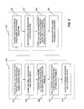
- Method 202 may also include defining spectral and time constraints to create a constrained optimization problem (step 206 ).
- the objective function may be defined to take the absolute value of each constraint, determine whether the value is larger than a constraint, and if so, take the square of the difference between the absolute value and the constraint. Thus, the objective function is higher valued in places where the constraint is not met, and quantifies how close the constraints are to being satisfied.
- Various defined constraints may include: (1) individual and composite time sidelobes, (2) individual and composite spectral sidelobes, (3) broadening characteristics, (4) mismatch filter losses, (5) waveform amplitude, etc.
- Method 202 may further include using a gradient descent method to solve the unconstrained optimization problem (step 210 ). Any suitable optimization technique may be used to solve the unconstrained optimization problem. However, in certain embodiments, a gradient descent method, such as the steepest descent method, or conjugate gradient method, may be desirable. Such methods may involve taking the gradient of the objective function with respect to each one of the individual components, and performing a 1-D line search in the negative gradient or similar direction to find a minimum. In one exemplary embodiment, a conjugate gradient method (e.g., Polak-Ribiere method) may be used, as will be described in more detail below.
- a conjugate gradient method e.g., Polak-Ribiere method
- g i is desired to be less than k i
- the method can further include obtaining gradients in the spectral domain (step 310 ).
- pulse compression may be performed in the frequency domain by (1) taking the Fourier transform of the signal to be compressed, (2) taking the Fourier transform of the filter to be compressed against, (3) conjugating one of the transformed values, (4) multiplying the two values, and (5) taking the inverse Fourier transform of the product.
- Performing pulse compression in the frequency domain may speed up pulse compression calculations by performing them at a speed on the order of log — 2(N)*N where N is the number of components of the vectorized signal.
- optimization in the spectral domain may be limited by the gradients that can be obtained in the spectral domain (i.e., the gradients that can be calculated using FFT techniques).
- the circular correlation ⁇ right arrow over (R) ⁇ ( ⁇ right arrow over (x) ⁇ , ⁇ right arrow over (y) ⁇ ) of the two vectors may be found by point-wise multiplication of the conjugate of the discrete Fourier transform of one of the vectors with the discrete Fourier transform of the other vector, and then applying an inverse Fourier transform to the result.
- the process of calculating the Fourier, and inverse Fourier transforms may be accomplished using FFT methods, but for simplicity of notation, may be expressed using an N ⁇ N discrete Fourier matrix denoted by the symbol F.
- F discrete Fourier transform
- ⁇ right arrow over (x) ⁇ F ⁇ 1 ⁇ right arrow over (X) ⁇
- ⁇ right arrow over (y) ⁇ F ⁇ 1 ⁇ right arrow over (Y) ⁇ .
- Equation (1) where ⁇ ⁇ right arrow over (R) ⁇ h is the gradient of h with respect to R (the correlated sidelobes), and F ⁇ right arrow over (x) ⁇ is the FFT, which maps the time domain ⁇ right arrow over (x) ⁇ into the frequency domain.
- equation (1) can be used to obtain the gradient of h( ⁇ right arrow over (R) ⁇ ( ⁇ right arrow over (x) ⁇ , ⁇ right arrow over (y) ⁇ )), the advantage being that the inverse FFT has taken the gradient back into the time domain.
- ⁇ ⁇ right arrow over (P) ⁇ ⁇ right arrow over (h) ⁇ is the gradient of ⁇ right arrow over (h) ⁇ with respect to ⁇ right arrow over (P) ⁇ (i.e., the vectorized power of the waveform in the spectral domain) and 2N ⁇ ⁇ right arrow over (P) ⁇ h ⁇ right arrow over (X) ⁇ is moved from the frequency domain back into time domain by the inverse FFT.
- the function ⁇ right arrow over (h) ⁇ ( ⁇ right arrow over (P) ⁇ ( ⁇ right arrow over (x) ⁇ )) can then be minimized using a conjugate gradient algorithm, which implements the gradient described in equation (2).
- the exemplary methods and systems described herein may be applied to any type of electromagnetic waveforms, such as communications waveforms.
- the presently disclosed systems and methods may be used for pulse compression processing of communications waveforms, so as to control and reduce unwanted spectral sidelobes that may interfere with communications in adjacent bandwidths.
Abstract
Description
Subject to P i({right arrow over (x)})≦c i , |x i|2 ≦d i and |x i|2 ≦d i
Minimize f({right arrow over (x)})
Subject to g i({right arrow over (x)})≦k i for i=1, . . . ,L.
into an unconstrained optimization. To accomplish this, a sequence of functions gp({right arrow over (x)}) may be formed for which:
g p({right arrow over (x)})h 1({right arrow over (R)}({right arrow over (x)},{right arrow over (x)}))+h 2({right arrow over (P)}({right arrow over (x)}))
∇{right arrow over (y)} h=F −1(conj(conj(F∇ {right arrow over (R)} h)∘F{right arrow over (x)})). (1)
where ∇{right arrow over (R)}h is the gradient of h with respect to R (the correlated sidelobes), and F{right arrow over (x)} is the FFT, which maps the time domain {right arrow over (x)} into the frequency domain. Thus, equation (1) can be used to obtain the gradient of h({right arrow over (R)}({right arrow over (x)},{right arrow over (y)})), the advantage being that the inverse FFT has taken the gradient back into the time domain.
∇{right arrow over (x)} {right arrow over (h)}=F −1(2N∇ {right arrow over (P)} {right arrow over (h)}◯{right arrow over (X)}). (2)
where ∇{right arrow over (P)}{right arrow over (h)} is the gradient of {right arrow over (h)} with respect to {right arrow over (P)} (i.e., the vectorized power of the waveform in the spectral domain) and 2N∇{right arrow over (P)}h◯{right arrow over (X)} is moved from the frequency domain back into time domain by the inverse FFT. Thus, the function {right arrow over (h)}({right arrow over (P)}({right arrow over (x)})) can then be minimized using a conjugate gradient algorithm, which implements the gradient described in equation (2). As described above, because the penalty method may be used to obtain gp({right arrow over (x)}) in the form: gp({right arrow over (x)})=h1({right arrow over (R)}({right arrow over (x)},{right arrow over (x)})+h2({right arrow over (P)}({right arrow over (x)})), the gradients ∇{right arrow over (x)}qp may be obtained using equations (1) and (2) above.
-
- 1. Let {right arrow over (g)}0=∇f({right arrow over (x)}0) and let {right arrow over (d)}0=−{right arrow over (g)}0.
- 2. For k=0 . . . n−1
- a. Let {right arrow over (x)}k+1={right arrow over (x)}k+αk{right arrow over (d)}k where αk minimizes f(x+α{right arrow over (d)}k)
- b. Compute {right arrow over (g)}k+1=∇f({right arrow over (x)}k+1)
- c. If k=n−1 go to step 3, otherwise let {right arrow over (d)}k+1=−{right arrow over (g)}k+1+βk{right arrow over (d)}k, where
-
- 3. Replace {right arrow over (x)}k by {right arrow over (x)}o and return to
step 1
until a suitable solution for {right arrow over (x)} is obtained. As described above, any obtained optimized waveform {right arrow over (x)} can then be saved, stored, and/or transmitted towaveform generator 103 for use in radar pulse compression system 100 (step 314).
- 3. Replace {right arrow over (x)}k by {right arrow over (x)}o and return to
Claims (34)
Priority Applications (2)
| Application Number | Priority Date | Filing Date | Title |
|---|---|---|---|
| US12/940,599 US8436766B1 (en) | 2009-11-06 | 2010-11-05 | Systems and methods for suppressing radar sidelobes using time and spectral control |
| US13/844,695 US8928524B1 (en) | 2009-11-06 | 2013-07-15 | Method and system for enhancing data rates |
Applications Claiming Priority (2)
| Application Number | Priority Date | Filing Date | Title |
|---|---|---|---|
| US25895009P | 2009-11-06 | 2009-11-06 | |
| US12/940,599 US8436766B1 (en) | 2009-11-06 | 2010-11-05 | Systems and methods for suppressing radar sidelobes using time and spectral control |
Related Child Applications (1)
| Application Number | Title | Priority Date | Filing Date |
|---|---|---|---|
| US13/844,695 Continuation-In-Part US8928524B1 (en) | 2009-11-06 | 2013-07-15 | Method and system for enhancing data rates |
Publications (1)
| Publication Number | Publication Date |
|---|---|
| US8436766B1 true US8436766B1 (en) | 2013-05-07 |
Family
ID=48183250
Family Applications (1)
| Application Number | Title | Priority Date | Filing Date |
|---|---|---|---|
| US12/940,599 Expired - Fee Related US8436766B1 (en) | 2009-11-06 | 2010-11-05 | Systems and methods for suppressing radar sidelobes using time and spectral control |
Country Status (1)
| Country | Link |
|---|---|
| US (1) | US8436766B1 (en) |
Cited By (11)
| Publication number | Priority date | Publication date | Assignee | Title |
|---|---|---|---|---|
| US20130176166A1 (en) * | 2010-10-07 | 2013-07-11 | Panasonic Corporation | Radar device |
| US8928524B1 (en) * | 2009-11-06 | 2015-01-06 | Technology Service Corporation | Method and system for enhancing data rates |
| US20150276917A1 (en) * | 2012-11-02 | 2015-10-01 | Qinetiq Limited | Radar imaging system |
| CN108226879A (en) * | 2017-12-21 | 2018-06-29 | 北京遥感设备研究所 | A kind of SAR landform scattering disturbance restraining method based on multichannel |
| CN108508414A (en) * | 2018-03-07 | 2018-09-07 | 北京理工大学 | A kind of secondary lobe suppressing method of the radar pulse compression output based on windowing process |
| CN108563611A (en) * | 2018-03-27 | 2018-09-21 | 天津大学 | Cognition radar waveform optimization method based on longicorn palpus searching algorithm |
| CN108738032A (en) * | 2018-04-25 | 2018-11-02 | 北京科技大学 | A kind of network work layout method based on gradient descent method |
| CN109459726A (en) * | 2018-11-12 | 2019-03-12 | 长沙莫之比智能科技有限公司 | Waveform design method, computer equipment and storage medium |
| CN111025253A (en) * | 2019-12-20 | 2020-04-17 | 西北工业大学 | Window function waveform joint design method for radar pulse compression processing |
| CN113238220A (en) * | 2021-04-12 | 2021-08-10 | 西安电子科技大学 | MIMO radar orthogonal phase coding design method based on SCAN algorithm |
| KR102336597B1 (en) * | 2020-09-03 | 2021-12-07 | 엘아이지넥스원 주식회사 | Apparatus and method for optimizing sidelobe cancelling function avoiding jamming signal |
Citations (52)
| Publication number | Priority date | Publication date | Assignee | Title |
|---|---|---|---|---|
| DE43825C (en) | A. L. G. DEHNE in Halle a. S | Mixing vessel for cleaning steam boiler feed water | ||
| US4042925A (en) | 1975-11-24 | 1977-08-16 | International Telephone And Telegraph Corporation | Pseudo-random code (PRC) surveilance radar |
| US4095225A (en) * | 1975-11-24 | 1978-06-13 | Telefonaktiebolaget L M Ericsson | Range side lobe suppression method for a phase modulated radar pulse |
| JPS5791468A (en) | 1980-11-28 | 1982-06-07 | Nec Corp | Suppressing circuit for narrow band disturbing signal |
| US4379295A (en) * | 1981-02-03 | 1983-04-05 | The United States Of America As Represented By The Secretary Of The Navy | Low sidelobe pulse compressor |
| US4566010A (en) * | 1982-04-28 | 1986-01-21 | Raytheon Company | Processing arrangement for pulse compression radar |
| US4580139A (en) * | 1983-06-22 | 1986-04-01 | The United States Of America As Represented By The Secretary Of The Army | Waveform design for optimized ambiguity response |
| US4591857A (en) | 1983-07-11 | 1986-05-27 | The United States Of America As Represented By The Secretary Of The Air Force | Programmable LFM signal processor |
| US4626853A (en) | 1984-07-20 | 1986-12-02 | Westinghouse Electric Corp. | Pulse compression radar signal processor |
| US4669051A (en) | 1984-01-09 | 1987-05-26 | Hewlett-Packard Company | Vector network analyzer with integral processor |
| DE3631586A1 (en) | 1986-09-17 | 1988-03-31 | Licentia Gmbh | Method for calibrating multi-channel direction finders |
| US4901082A (en) | 1988-11-17 | 1990-02-13 | Grumman Aerospace Corporation | Adaptive waveform radar |
| US5036328A (en) | 1989-05-31 | 1991-07-30 | Nec Corporation | Pulse compressing apparatus for a radar system using a long pulse |
| US5070337A (en) * | 1991-04-05 | 1991-12-03 | Chen Xiao H | Optimization method and an optimized filter for sidelobe suppression |
| US5115244A (en) | 1991-04-16 | 1992-05-19 | General Electric Company | Radar system with active array antenna, elevation-responsive PRF control, and pulse integration control responsive to azimuth angle |
| US5128683A (en) | 1991-04-16 | 1992-07-07 | General Electric Company | Radar system with active array antenna, elevation-responsive PRF control, and beam multiplex control |
| GB2259209A (en) | 1980-07-25 | 1993-03-03 | Siemens Ag | Radar receivers |
| US5309161A (en) | 1992-12-10 | 1994-05-03 | General Electric Co. | Radar with doppler tolerant range sidelobe suppression and time domain signal processing |
| DE4240225A1 (en) | 1991-05-31 | 1994-06-01 | Deutsche Forsch Luft Raumfahrt | Generating correction function eliminating phase and amplitude errors in compressed signal - producing Fourier transform reference functions of ideal and optimal filters to provide correction function in time range of inverse Fourier transform |
| US5389933A (en) * | 1992-10-07 | 1995-02-14 | Grumman Aerospace Corporation | Linear pulse compression radar system and method |
| US5414428A (en) * | 1993-08-06 | 1995-05-09 | Martin Marietta Corp. | Radar system with pulse compression and range sidelobe suppression preceding doppler filtering |
| US5440311A (en) * | 1993-08-06 | 1995-08-08 | Martin Marietta Corporation | Complementary-sequence pulse radar with matched filtering and Doppler tolerant sidelobe suppression preceding Doppler filtering |
| US5481270A (en) * | 1994-03-04 | 1996-01-02 | Martin Marietta Corporation | Radar with adaptive range sidelobe suppression |
| US5497160A (en) | 1993-09-17 | 1996-03-05 | Motorola, Inc. | Method and apparatus for improved auto-correlation and range correlation in pseudo-random noise coded systems |
| US5568150A (en) | 1995-07-31 | 1996-10-22 | Northrop Grumman Corporation | Method and apparatus for hybrid analog-digital pulse compression |
| US5708436A (en) | 1996-06-24 | 1998-01-13 | Northrop Grumman Corporation | Multi-mode radar system having real-time ultra high resolution synthetic aperture radar (SAR) capability |
| US5731784A (en) | 1996-07-18 | 1998-03-24 | Northrop Grumman Corporation | Adaptive pulse shaping implementation and method for control of solid state transmitter spectrum and time sidelobes |
| US5786788A (en) * | 1996-10-08 | 1998-07-28 | Raytheon Company | Radar system and method for reducing range sidelobes |
| US5808580A (en) | 1997-02-06 | 1998-09-15 | Andrews, Jr.; Grealie A. | Radar/sonar system concept for extended range-doppler coverage |
| US5812082A (en) | 1996-03-13 | 1998-09-22 | Deutsche Forschungsanstalt Fur Luft-Und Raumfahrt E.V. | Method for azimuth scaling of SAR data and highly accurate processor for two-dimensional processing of scanSAR data |
| US6044336A (en) * | 1998-07-13 | 2000-03-28 | Multispec Corporation | Method and apparatus for situationally adaptive processing in echo-location systems operating in non-Gaussian environments |
| US6061589A (en) | 1994-07-01 | 2000-05-09 | Interstitial, Inc. | Microwave antenna for cancer detection system |
| US6067043A (en) | 1998-03-23 | 2000-05-23 | Alcatel | Pulse compression radar |
| US6078281A (en) | 1996-06-28 | 2000-06-20 | Milkovich Systems Engineering | Signal processing architecture which improves sonar and pulse Doppler radar performance and tracking capability |
| US6255985B1 (en) * | 1999-01-11 | 2001-07-03 | Lockheed Martin Corporation | Method and apparatus for optimizing radar system performance |
| US6392588B1 (en) | 2000-05-03 | 2002-05-21 | Ramot University Authority For Applied Research & Industrial Development Ltd. | Multifrequency signal structure for radar systems |
| US6405147B1 (en) | 1999-09-10 | 2002-06-11 | Condor Systems, Inc. | Signal transfer device measurement system and method |
| US6704438B1 (en) | 2000-05-08 | 2004-03-09 | Aloka Co., Ltd. | Apparatus and method for improving the signal to noise ratio on ultrasound images using coded waveforms |
| US6781541B1 (en) | 2003-07-30 | 2004-08-24 | Raytheon Company | Estimation and correction of phase for focusing search mode SAR images formed by range migration algorithm |
| US6822606B2 (en) | 2002-03-13 | 2004-11-23 | Raytheon Canada Limited | System and method for spectral generation in radar |
| US6879281B2 (en) | 2002-03-22 | 2005-04-12 | M/A - Com, Inc. | Pulse radar detection system |
| US6977609B2 (en) | 2000-08-16 | 2005-12-20 | Raytheon Company | Technique for changing a range gate and radar coverage |
| US7019686B2 (en) | 2004-02-27 | 2006-03-28 | Honeywell International Inc. | RF channel calibration for non-linear FM waveforms |
| US7151483B2 (en) | 2004-05-03 | 2006-12-19 | Raytheon Company | System and method for concurrent operation of multiple radar or active sonar systems on a common frequency |
| US7151484B2 (en) | 2003-09-30 | 2006-12-19 | Kabushiki Kaisha Toshiba | Pulse compression processor |
| US20060284757A1 (en) * | 2004-09-14 | 2006-12-21 | Zemany Paul D | Through-the-wall frequency stepped imaging system utilizing near field multiple antenna positions, clutter rejection and corrections for frequency dependent wall effects |
| US20080037611A1 (en) * | 2006-08-11 | 2008-02-14 | Kabushiki Kaisha Toshiba | Dynamic optimisation of block transmissions for interference avoidance |
| US20080111734A1 (en) * | 2006-11-14 | 2008-05-15 | Fam Adly T | Multiplicative mismatched filters for optimum range sidelobe suppression in Barker code reception |
| US20080136704A1 (en) | 2006-12-06 | 2008-06-12 | Tony Meng Yuen Chan | Method and system for concatenation of radar pulses |
| US20100067615A1 (en) * | 2007-03-15 | 2010-03-18 | Nokia Siemens Networks Gmbh & Co. Kg | Method for Optimizing Signals with Multiple Subcarriers |
| US20100149022A1 (en) * | 2008-12-15 | 2010-06-17 | Fam Adly T | Mismatched Filter |
| US20110241931A1 (en) * | 2010-04-01 | 2011-10-06 | Massachusetts Institute Of Technology | Iterative clutter calibration with phased array antennas |
-
2010
- 2010-11-05 US US12/940,599 patent/US8436766B1/en not_active Expired - Fee Related
Patent Citations (54)
| Publication number | Priority date | Publication date | Assignee | Title |
|---|---|---|---|---|
| DE43825C (en) | A. L. G. DEHNE in Halle a. S | Mixing vessel for cleaning steam boiler feed water | ||
| US4042925A (en) | 1975-11-24 | 1977-08-16 | International Telephone And Telegraph Corporation | Pseudo-random code (PRC) surveilance radar |
| US4095225A (en) * | 1975-11-24 | 1978-06-13 | Telefonaktiebolaget L M Ericsson | Range side lobe suppression method for a phase modulated radar pulse |
| GB2259209A (en) | 1980-07-25 | 1993-03-03 | Siemens Ag | Radar receivers |
| JPS5791468A (en) | 1980-11-28 | 1982-06-07 | Nec Corp | Suppressing circuit for narrow band disturbing signal |
| US4379295A (en) * | 1981-02-03 | 1983-04-05 | The United States Of America As Represented By The Secretary Of The Navy | Low sidelobe pulse compressor |
| US4566010A (en) * | 1982-04-28 | 1986-01-21 | Raytheon Company | Processing arrangement for pulse compression radar |
| US4580139A (en) * | 1983-06-22 | 1986-04-01 | The United States Of America As Represented By The Secretary Of The Army | Waveform design for optimized ambiguity response |
| US4591857A (en) | 1983-07-11 | 1986-05-27 | The United States Of America As Represented By The Secretary Of The Air Force | Programmable LFM signal processor |
| US4669051A (en) | 1984-01-09 | 1987-05-26 | Hewlett-Packard Company | Vector network analyzer with integral processor |
| US4626853A (en) | 1984-07-20 | 1986-12-02 | Westinghouse Electric Corp. | Pulse compression radar signal processor |
| DE3631586A1 (en) | 1986-09-17 | 1988-03-31 | Licentia Gmbh | Method for calibrating multi-channel direction finders |
| US4901082A (en) | 1988-11-17 | 1990-02-13 | Grumman Aerospace Corporation | Adaptive waveform radar |
| US5036328A (en) | 1989-05-31 | 1991-07-30 | Nec Corporation | Pulse compressing apparatus for a radar system using a long pulse |
| US5070337A (en) * | 1991-04-05 | 1991-12-03 | Chen Xiao H | Optimization method and an optimized filter for sidelobe suppression |
| US5115244A (en) | 1991-04-16 | 1992-05-19 | General Electric Company | Radar system with active array antenna, elevation-responsive PRF control, and pulse integration control responsive to azimuth angle |
| US5128683A (en) | 1991-04-16 | 1992-07-07 | General Electric Company | Radar system with active array antenna, elevation-responsive PRF control, and beam multiplex control |
| DE4240225A1 (en) | 1991-05-31 | 1994-06-01 | Deutsche Forsch Luft Raumfahrt | Generating correction function eliminating phase and amplitude errors in compressed signal - producing Fourier transform reference functions of ideal and optimal filters to provide correction function in time range of inverse Fourier transform |
| US5389933A (en) * | 1992-10-07 | 1995-02-14 | Grumman Aerospace Corporation | Linear pulse compression radar system and method |
| US5309161A (en) | 1992-12-10 | 1994-05-03 | General Electric Co. | Radar with doppler tolerant range sidelobe suppression and time domain signal processing |
| US5414428A (en) * | 1993-08-06 | 1995-05-09 | Martin Marietta Corp. | Radar system with pulse compression and range sidelobe suppression preceding doppler filtering |
| US5440311A (en) * | 1993-08-06 | 1995-08-08 | Martin Marietta Corporation | Complementary-sequence pulse radar with matched filtering and Doppler tolerant sidelobe suppression preceding Doppler filtering |
| US5497160A (en) | 1993-09-17 | 1996-03-05 | Motorola, Inc. | Method and apparatus for improved auto-correlation and range correlation in pseudo-random noise coded systems |
| US5481270A (en) * | 1994-03-04 | 1996-01-02 | Martin Marietta Corporation | Radar with adaptive range sidelobe suppression |
| US6061589A (en) | 1994-07-01 | 2000-05-09 | Interstitial, Inc. | Microwave antenna for cancer detection system |
| US5568150A (en) | 1995-07-31 | 1996-10-22 | Northrop Grumman Corporation | Method and apparatus for hybrid analog-digital pulse compression |
| US5812082A (en) | 1996-03-13 | 1998-09-22 | Deutsche Forschungsanstalt Fur Luft-Und Raumfahrt E.V. | Method for azimuth scaling of SAR data and highly accurate processor for two-dimensional processing of scanSAR data |
| US5708436A (en) | 1996-06-24 | 1998-01-13 | Northrop Grumman Corporation | Multi-mode radar system having real-time ultra high resolution synthetic aperture radar (SAR) capability |
| US6078281A (en) | 1996-06-28 | 2000-06-20 | Milkovich Systems Engineering | Signal processing architecture which improves sonar and pulse Doppler radar performance and tracking capability |
| US5731784A (en) | 1996-07-18 | 1998-03-24 | Northrop Grumman Corporation | Adaptive pulse shaping implementation and method for control of solid state transmitter spectrum and time sidelobes |
| US5786788A (en) * | 1996-10-08 | 1998-07-28 | Raytheon Company | Radar system and method for reducing range sidelobes |
| US5808580A (en) | 1997-02-06 | 1998-09-15 | Andrews, Jr.; Grealie A. | Radar/sonar system concept for extended range-doppler coverage |
| US6067043A (en) | 1998-03-23 | 2000-05-23 | Alcatel | Pulse compression radar |
| US6044336A (en) * | 1998-07-13 | 2000-03-28 | Multispec Corporation | Method and apparatus for situationally adaptive processing in echo-location systems operating in non-Gaussian environments |
| US6255985B1 (en) * | 1999-01-11 | 2001-07-03 | Lockheed Martin Corporation | Method and apparatus for optimizing radar system performance |
| US6405147B1 (en) | 1999-09-10 | 2002-06-11 | Condor Systems, Inc. | Signal transfer device measurement system and method |
| US6392588B1 (en) | 2000-05-03 | 2002-05-21 | Ramot University Authority For Applied Research & Industrial Development Ltd. | Multifrequency signal structure for radar systems |
| US6704438B1 (en) | 2000-05-08 | 2004-03-09 | Aloka Co., Ltd. | Apparatus and method for improving the signal to noise ratio on ultrasound images using coded waveforms |
| US6977609B2 (en) | 2000-08-16 | 2005-12-20 | Raytheon Company | Technique for changing a range gate and radar coverage |
| US6822606B2 (en) | 2002-03-13 | 2004-11-23 | Raytheon Canada Limited | System and method for spectral generation in radar |
| US6879281B2 (en) | 2002-03-22 | 2005-04-12 | M/A - Com, Inc. | Pulse radar detection system |
| US6781541B1 (en) | 2003-07-30 | 2004-08-24 | Raytheon Company | Estimation and correction of phase for focusing search mode SAR images formed by range migration algorithm |
| US7151484B2 (en) | 2003-09-30 | 2006-12-19 | Kabushiki Kaisha Toshiba | Pulse compression processor |
| US7019686B2 (en) | 2004-02-27 | 2006-03-28 | Honeywell International Inc. | RF channel calibration for non-linear FM waveforms |
| US7151483B2 (en) | 2004-05-03 | 2006-12-19 | Raytheon Company | System and method for concurrent operation of multiple radar or active sonar systems on a common frequency |
| US20060284757A1 (en) * | 2004-09-14 | 2006-12-21 | Zemany Paul D | Through-the-wall frequency stepped imaging system utilizing near field multiple antenna positions, clutter rejection and corrections for frequency dependent wall effects |
| US20080037611A1 (en) * | 2006-08-11 | 2008-02-14 | Kabushiki Kaisha Toshiba | Dynamic optimisation of block transmissions for interference avoidance |
| US20080111734A1 (en) * | 2006-11-14 | 2008-05-15 | Fam Adly T | Multiplicative mismatched filters for optimum range sidelobe suppression in Barker code reception |
| US7492312B2 (en) * | 2006-11-14 | 2009-02-17 | Fam Adly T | Multiplicative mismatched filters for optimum range sidelobe suppression in barker code reception |
| US20080136704A1 (en) | 2006-12-06 | 2008-06-12 | Tony Meng Yuen Chan | Method and system for concatenation of radar pulses |
| US20100067615A1 (en) * | 2007-03-15 | 2010-03-18 | Nokia Siemens Networks Gmbh & Co. Kg | Method for Optimizing Signals with Multiple Subcarriers |
| US20100149022A1 (en) * | 2008-12-15 | 2010-06-17 | Fam Adly T | Mismatched Filter |
| US7843382B2 (en) * | 2008-12-15 | 2010-11-30 | Adly T. Fam | Mismatched filter |
| US20110241931A1 (en) * | 2010-04-01 | 2011-10-06 | Massachusetts Institute Of Technology | Iterative clutter calibration with phased array antennas |
Non-Patent Citations (11)
| Title |
|---|
| "Multi-Parameter Local Optimization for the Design of Superior Matched Filter Polyphase Pulse Compression Codes", Nunn, Carroll J. IEEE International Radar Conference, pp. 435-440, 2000. * |
| Adly T. Fam et al., Multiplicative Mismatched Filter for Optimum Sidelobe Suppression in Barker Codes. |
| Carroll Nunn et al., Multi-Parameter Local Optimization for the Design of Superior Matched Filter Polyphase Pulse Compression Codes, First pulse compression paper, presented at Radar 2000 Conference, 2000. |
| Carroll Nunn et al., Performance of Pulse Compression Code and Filter Pairs Optimized for Loss and Integrated Sidelobe Level, Radar 2007 Conference, 2007. |
| Carroll Nunn et al., Polyphase Pulse Compression Codes with Optimal Peak and Integrated Sidelobes. |
| Carroll Nunn et al., Real Time Compatible, Phase Only Pattern Notching Algorithm for Very Large Arrays, Tri-Service Conference, Jun. 2006. |
| Carroll Nunn, A Modulation and De-Modulation Technique for Quadraphase Pulse Compression Codes, poster session at Radar 2005 Conference, 2005. |
| Carroll Nunn, Constrained Optimization Applied to Pulse Compression Codes, and Filters, presented at Radar 2005 Conference, 2005. |
| Michael J. Lindenfeld, Sparse Frequency Transmit and Receive Waveform Design, IEEE Transactions on Aaerospace and Electronic Systems, vol. 40, No. 3, Jul. 3, 2004, pp. 851-860. |
| S.D. Green et al., Improving the Range/Time Sidelobes of Large Bandwidth Discontinuous Spectra HF Radar Waveforms, HF Radio Systems and Techniques, Jul. 7-10, 1997, Conferecne Publication No. 411, pp. 246-250. |
| S.D. Green et al., Investigation of wide bandwidth HF radar waveforms, 1995 The Institution of Electrical Engineers, pp. 2/1 to 2/8. |
Cited By (18)
| Publication number | Priority date | Publication date | Assignee | Title |
|---|---|---|---|---|
| US8928524B1 (en) * | 2009-11-06 | 2015-01-06 | Technology Service Corporation | Method and system for enhancing data rates |
| US9239378B2 (en) * | 2010-10-07 | 2016-01-19 | Panasonic Intellectual Property Management Co., Ltd. | Radar device |
| US20130176166A1 (en) * | 2010-10-07 | 2013-07-11 | Panasonic Corporation | Radar device |
| US20150276917A1 (en) * | 2012-11-02 | 2015-10-01 | Qinetiq Limited | Radar imaging system |
| US10502821B2 (en) * | 2012-11-02 | 2019-12-10 | Qinetiq Limited | Radar imaging system |
| CN108226879B (en) * | 2017-12-21 | 2021-08-13 | 北京遥感设备研究所 | SAR terrain scattering interference suppression method based on multiple channels |
| CN108226879A (en) * | 2017-12-21 | 2018-06-29 | 北京遥感设备研究所 | A kind of SAR landform scattering disturbance restraining method based on multichannel |
| CN108508414A (en) * | 2018-03-07 | 2018-09-07 | 北京理工大学 | A kind of secondary lobe suppressing method of the radar pulse compression output based on windowing process |
| CN108508414B (en) * | 2018-03-07 | 2020-08-11 | 北京理工大学 | Sidelobe suppression method for radar pulse compression output based on windowing processing |
| CN108563611A (en) * | 2018-03-27 | 2018-09-21 | 天津大学 | Cognition radar waveform optimization method based on longicorn palpus searching algorithm |
| CN108563611B (en) * | 2018-03-27 | 2022-03-11 | 天津大学 | Cognitive radar waveform optimization method based on longicorn stigma search algorithm |
| CN108738032A (en) * | 2018-04-25 | 2018-11-02 | 北京科技大学 | A kind of network work layout method based on gradient descent method |
| CN109459726A (en) * | 2018-11-12 | 2019-03-12 | 长沙莫之比智能科技有限公司 | Waveform design method, computer equipment and storage medium |
| CN109459726B (en) * | 2018-11-12 | 2020-12-01 | 长沙莫之比智能科技有限公司 | Waveform design method, computer device, and storage medium |
| CN111025253A (en) * | 2019-12-20 | 2020-04-17 | 西北工业大学 | Window function waveform joint design method for radar pulse compression processing |
| CN111025253B (en) * | 2019-12-20 | 2023-02-17 | 西北工业大学 | Window function waveform joint design method for radar pulse compression processing |
| KR102336597B1 (en) * | 2020-09-03 | 2021-12-07 | 엘아이지넥스원 주식회사 | Apparatus and method for optimizing sidelobe cancelling function avoiding jamming signal |
| CN113238220A (en) * | 2021-04-12 | 2021-08-10 | 西安电子科技大学 | MIMO radar orthogonal phase coding design method based on SCAN algorithm |
Similar Documents
| Publication | Publication Date | Title |
|---|---|---|
| US8436766B1 (en) | Systems and methods for suppressing radar sidelobes using time and spectral control | |
| Jin et al. | An advanced nonlinear frequency modulation waveform for radar imaging with low sidelobe | |
| US8571508B2 (en) | Method and wideband antenna system to minimise the influence of interference sources | |
| Patton et al. | Efficient design of radar waveforms for optimised detection in coloured noise | |
| JP4834370B2 (en) | Correlation reception processing device | |
| Wang | MIMO SAR chirp modulation diversity waveform design | |
| Wang et al. | Manoeuvring target detection in over-the-horizon radar using adaptive clutter rejection and adaptive chirplet transform | |
| CN109471064B (en) | Time modulation array direction-finding system based on pulse compression technology | |
| US8928524B1 (en) | Method and system for enhancing data rates | |
| Li et al. | A waveform design method for suppressing range sidelobes in desired intervals | |
| Jakabosky et al. | Ultra-low sidelobe waveform design via spectral shaping and LINC transmit architecture | |
| CN113376601B (en) | Frequency agile radar sidelobe suppression method based on CLEAN algorithm | |
| Kumar et al. | Intrapulse polyphase coding system for second trip suppression in a weather radar | |
| Kulpa et al. | Filter-based design of noise radar waveform with reduced sidelobes | |
| EP1521097B1 (en) | Pulse compression processor | |
| KR20160012284A (en) | Method and Apparatus for suppressing jammer signals and estimating Angle Of Arrival of original signal using orthogonal of transmitting signal waveform | |
| Wang et al. | Precise calibration of channel imbalance for very high resolution SAR with stepped frequency | |
| Yang et al. | Two-dimensional spectral analysis filter for removal of LFM radar interference in spaceborne SAR imagery | |
| JP2005085167A (en) | Correlation processing device and method, and pulse compression processing device and method | |
| Xu et al. | Simultaneous optimization of radar waveform and mismatched filter with range and delay-Doppler sidelobes suppression | |
| JP5566261B2 (en) | Radar equipment | |
| JP4444057B2 (en) | Pulse compression processor | |
| Higgins | Waveform diversity and range-coupled adaptive radar signal processing | |
| KR102192332B1 (en) | Advanced method for mitigating leakage signal in fmcw radar and radar system therefor | |
| CN104101868A (en) | Jamming subspace reconstruction-based radar multi-false target jamming suppression method |
Legal Events
| Date | Code | Title | Description |
|---|---|---|---|
| AS | Assignment |
Owner name: TECHNOLOGY SERVICE CORPORATION, MARYLAND Free format text: ASSIGNMENT OF ASSIGNORS INTEREST;ASSIGNOR:NUNN, CARROLL J.;REEL/FRAME:025321/0858 Effective date: 20101104 |
|
| STCF | Information on status: patent grant |
Free format text: PATENTED CASE |
|
| FPAY | Fee payment |
Year of fee payment: 4 |
|
| FEPP | Fee payment procedure |
Free format text: MAINTENANCE FEE REMINDER MAILED (ORIGINAL EVENT CODE: REM.); ENTITY STATUS OF PATENT OWNER: SMALL ENTITY |
|
| LAPS | Lapse for failure to pay maintenance fees |
Free format text: PATENT EXPIRED FOR FAILURE TO PAY MAINTENANCE FEES (ORIGINAL EVENT CODE: EXP.); ENTITY STATUS OF PATENT OWNER: SMALL ENTITY |
|
| STCH | Information on status: patent discontinuation |
Free format text: PATENT EXPIRED DUE TO NONPAYMENT OF MAINTENANCE FEES UNDER 37 CFR 1.362 |
|
| FP | Lapsed due to failure to pay maintenance fee |
Effective date: 20210507 |