US8435465B2 - Microfluidic biological extraction chip - Google Patents
Microfluidic biological extraction chip Download PDFInfo
- Publication number
- US8435465B2 US8435465B2 US12/263,911 US26391108A US8435465B2 US 8435465 B2 US8435465 B2 US 8435465B2 US 26391108 A US26391108 A US 26391108A US 8435465 B2 US8435465 B2 US 8435465B2
- Authority
- US
- United States
- Prior art keywords
- chamber
- loop
- lysis
- capture
- elution
- Prior art date
- Legal status (The legal status is an assumption and is not a legal conclusion. Google has not performed a legal analysis and makes no representation as to the accuracy of the status listed.)
- Active, expires
Links
Images


Classifications
-
- C—CHEMISTRY; METALLURGY
- C12—BIOCHEMISTRY; BEER; SPIRITS; WINE; VINEGAR; MICROBIOLOGY; ENZYMOLOGY; MUTATION OR GENETIC ENGINEERING
- C12N—MICROORGANISMS OR ENZYMES; COMPOSITIONS THEREOF; PROPAGATING, PRESERVING, OR MAINTAINING MICROORGANISMS; MUTATION OR GENETIC ENGINEERING; CULTURE MEDIA
- C12N15/00—Mutation or genetic engineering; DNA or RNA concerning genetic engineering, vectors, e.g. plasmids, or their isolation, preparation or purification; Use of hosts therefor
- C12N15/09—Recombinant DNA-technology
- C12N15/10—Processes for the isolation, preparation or purification of DNA or RNA
- C12N15/1003—Extracting or separating nucleic acids from biological samples, e.g. pure separation or isolation methods; Conditions, buffers or apparatuses therefor
- C12N15/1006—Extracting or separating nucleic acids from biological samples, e.g. pure separation or isolation methods; Conditions, buffers or apparatuses therefor by means of a solid support carrier, e.g. particles, polymers
-
- C—CHEMISTRY; METALLURGY
- C12—BIOCHEMISTRY; BEER; SPIRITS; WINE; VINEGAR; MICROBIOLOGY; ENZYMOLOGY; MUTATION OR GENETIC ENGINEERING
- C12M—APPARATUS FOR ENZYMOLOGY OR MICROBIOLOGY; APPARATUS FOR CULTURING MICROORGANISMS FOR PRODUCING BIOMASS, FOR GROWING CELLS OR FOR OBTAINING FERMENTATION OR METABOLIC PRODUCTS, i.e. BIOREACTORS OR FERMENTERS
- C12M47/00—Means for after-treatment of the produced biomass or of the fermentation or metabolic products, e.g. storage of biomass
- C12M47/06—Hydrolysis; Cell lysis; Extraction of intracellular or cell wall material
-
- Y—GENERAL TAGGING OF NEW TECHNOLOGICAL DEVELOPMENTS; GENERAL TAGGING OF CROSS-SECTIONAL TECHNOLOGIES SPANNING OVER SEVERAL SECTIONS OF THE IPC; TECHNICAL SUBJECTS COVERED BY FORMER USPC CROSS-REFERENCE ART COLLECTIONS [XRACs] AND DIGESTS
- Y10—TECHNICAL SUBJECTS COVERED BY FORMER USPC
- Y10T—TECHNICAL SUBJECTS COVERED BY FORMER US CLASSIFICATION
- Y10T436/00—Chemistry: analytical and immunological testing
- Y10T436/11—Automated chemical analysis
Definitions
- the present invention is a microfluidics-based cartridge for automated extraction of biological molecules from cells, spores, virions, their lysates, and other biological samples.
- the present invention is capable of isolating nucleic acids, proteins, and other biological macromolecules from less than 10,000 cells in 30 minutes.
- Microfluidic apparatus and methods for the lysis of cells and/or separation of selected lysate components are known in the art.
- U.S. Pat. No. 6,287,831 B1 to Tai et al. discloses a cell lysis device in which micromachined electrodes spaced less than 100 micrometers apart on a silicon substrate are used to lyse cells.
- US 2007/0134809 discloses a microfluidic device for the concentration and lysis of cells or viruses in which lysis is accomplished by radiating magnetic beads in a reaction chamber with a laser.
- US 2004/0058423 A1 discloses an apparatus for sequential lysis of selected adherent cells in which a single electric pulse of between 10 milliseconds and 10 microseconds is used to lyse cells and lysate is transferred into a microcollection device.
- U.S. Pat. No. 7,169,277 B2 to Ausserer et al. discloses a device that separates sample materials into different fractions using a combination of bulk flow for loading samples and electrophoretic separation of sample materials.
- a microfluidic cartridge and associated method for selective lysis of and extraction of DNA from cell mixtures is disclosed in US 2005/0064598 A1 (Yuan et al.).
- the microfluidic differential extraction cartridge selectively lyses one of at least two populations of cells in a mixed sample using sonication at frequencies capable of lysing on cell type and not another.
- the differential extraction is based on the selective lysis of one cell type over another using, for example, sonication to selectively lyse one cell type and chemicals or heat to lyse a second cell type.
- the cartridge comprises a sample input chamber, a sonication lysis chamber, a means for separating lysed cells from intact cells, and a collection vessel to collect cell lysate.
- the cartridge may comprise a mixing chamber to add and mix a solution into a cell lysate and a purification chip to purify and concentrate nucleic acid from the cell lysate.
- the utility of existing microfluidic systems for cell lysis and isolation is, in some cases, limited due to high internal pressure drops required to achieve acceptable flow rates, capture and elution times, and bubble formation.
- the present invention overcomes these limitations by providing a capture chamber containing beads that bind the target species to be captured wherein the beads are maintained in a fluidized state.
- the present invention is a microfluidic extraction cartridge and method comprising a bead-based capture and elution chamber comprising a loosely packed, fluidized solid supports, such as beads.
- loosely packed, fluidized it is meant that the solid supports are not static, as in a packed column, but rather free to move relative to one another such that the supports may flow like a liquid.
- the chamber containing the solid supports and the chamber inlets and outlets are configured in a way that increases reagent contact and reduces bubble formation relative to existing devices. Electrokinetic mixing can be incorporated to reduce mixing, capture, and elution times.
- the present capture chamber provides for a lower pressure drop across the chamber.
- the shape of the capture chamber and relative positions of the inlet to and outlet from the chamber may be designed to reduced bubble formation and maximized contact between solution and beads. For instance, a disc shaped capture chamber is preferred to minimize bubble formation and maximize contact between fluid and the beads.
- the present invention is an electric field lysis chamber comprising embedded, insulating structures between two parallel, flat electrodes used to generate strong electric field gradients in the gaps between the insulating structures.
- This configuration simplifies and reduces the cost of manufacture compared to known microfluidic electric field lysis chambers.
- a wedge electrode design is known in which the electrode surfaces form wedge shapes to generate electric fields having local field intensities capable of lysing cells. Patterned electrode structures, while being the most direct way of attaining the large electric fields needed for cell lysis, introduce significant complexities related to the manufacturing process, biofouling, bubble formation, and electrochemical reactions.
- the electric field lysis chamber of the present invention does not require metal electrodes having patterned electrode geometries. Instead, the electric field originates at the surface of electrodes and passes through the insulating structures, leading to sustained, strong electric fields across the flow path and efficient lysis.
- the present invention is an extraction cartridge comprising one, two, or more lysis chambers and a capture chamber comprising fluidized beads.
- the beads are functionalized to bind to nucleic acids or other target biomolecules and are held in the capture chamber by bead containment membranes.
- the beads are maintained in a fluidized state by using electric fields generated using electrodes located in the capture chamber.
- the electrokinetic flows improve the contacting and mixing between the beads and the target, thereby reducing the contacting time capture onto and elution from the bead surface.
- FIG. 1 is an idealized layout of a preferred embodiment of a microfluidic extraction cartridge with lysis and capture chambers and loops labeled.
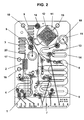
- FIG. 2 is a CAD drawing of a preferred embodiment of a microfluidic extraction cartridge according to the present invention with lysis and capture chambers and loops labeled.
- FIG. 3 is a CAD drawing of a preferred embodiment of a microfluidic extraction cartridge according to the present invention with valves labeled.
- FIG. 4 is a table showing the valve operation logic of a preferred embodiment of a microfluidic extraction cartridge.
- FIG. 5 shows a top view of a diagram of an electric field lysis chamber comprising insulating posts separating two planar electrodes.
- FIG. 6 shows a top view of a diagram of an electric field lysis chamber comprising cubic-packed insulating posts between two planar electrodes.
- FIG. 7 shows a top view of a diagram of an electric field lysis chamber comprising hex-packed insulating posts between two planar electrodes.
- FIG. 8 is a diagram of an electric field lysis chamber comprising a porous, electronically insulating gasket separating two planar electrodes.
- FIGS. 9 (A) and (B) show side cross-section and exploded perspective views of an electric field lysis chamber comprising a porous, electronically insulating gasket separating two planar electrodes.
- FIG. 1 illustrates the layout of a first embodiment of a microfluidic extraction cartridge.
- the cartridge is configured for the extraction of nucleic acids from cells or cell lysate but other embodiments may be configured for the extraction of protein, protein fractions, or other cellular contents by altering the binding properties of the beads used for molecular capture.
- the lysis chambers may be configured and operated to disrupt other sources of DNA or RNA such as viruses or bacterial or fungal spores. Table 1 lists the structural elements identified in FIG. 1 .
- Sample Loop 1 may be loaded with cells, spores, virions or other lysable sources of nucleic acids or other biomolecules suspended in buffer solution.
- Two lysis chambers are present in the preferred embodiment of the invention; a Chemical Lysis Chamber and an Electric Field Lysis Chamber.
- the term chemical lysis is meant to include enzymatic as well as purely chemical lysis.
- Electric Field Lysis Chamber 2 and Chemical Lysis Chamber 3 may be arranged in parallel or in series, and may be both used for the lysis of the same sample, used simultaneously for lysis of the same sample, or used at different times to lyse different samples. In embodiments having a second sample loop, different samples may be lysed simultaneously in the two lysis chambers. If chemical lysis is used, reagents are loaded into Chemical Lysis Reagent Loop 4 for delivery to Chemical Lysis Chamber 3 .
- Lysate Filter Membrane 5 traps cell lysate debris and prevents clogging of the downstream channels and chambers due to the presence of the debris. Additional lysate filters may be arranged in series and/or in parallel to facilitate processing of multiple samples.
- Contacting Loops 9 allow cell lysate to interact with nucleases delivered from Nuclease Solution Loop 7 .
- DNAse may be delivered from Nuclease Solution Loop 7 to degrade DNA for isolation of RNA or RNAse may be delivered from Nuclease Solution Loop 7 to degrade RNA for isolation of DNA.
- Other embodiments may include one or more of DNAse, RNAse or protease loops, for example, depending on the type of molecule being isolated.
- Capture Chamber 11 is loaded through Bead Injection Port 12 with beads (magnetic or non-magnetic) functionalized to bind to nucleic acids or other target biomolecules and maintained in a fluidized state.
- the beads are held in the capture chamber by Bead Containment Membranes 10 and are maintained in a fluidized state by fluidic flow or by using electric fields generated using electrodes located in the capture chamber.
- Bead Containment Membranes 10 are preferably asymmetric membranes having a smaller pore size (e.g., 0.8 ⁇ m) on the bead side and a larger pore size (e.g., 10 ⁇ m) on the port side.
- the surface area of the membranes exposed to fluid flow is preferably maximized to minimize fluidic resistance and each membrane is preferably supported by a structure incorporated into each membrane mount to prevent membrane collapse.
- the Capture Chamber 11 lacks sharp corners and contains fluidized beads, functionalized to bind selected targeted cellular contents such as RNA, DNA, and proteins.
- the capture chamber is circular in shape.
- Staggered saw-tooth electrodes may be placed on the floor of the capture chamber and energized with ⁇ 15V at alternate electrode strips to actively mix chamber contents.
- the chamber contents may be mixed actively by using bidirectional pumping by connecting a external fluidic pump to the extraction cartridge at access port 20 .
- Wash Buffer Loop 6 and Elution Buffer Loop 8 provide buffer solutions for washing the target biomolecules bound to the beads and eluting nucleic acids from the beads.
- the purified biomolecule is stored in the Product Storage Chamber 14 until removed from the cartridge using an access port 15 .
- An extraction cartridge having the design shown in FIG. 1 may be used for the extraction and purification of RNA, DNA, protein, or other biological material from suspended cells, viruses, spores, or other biological samples. Isolation is performed using small volumes of sample of typically between 0.1 and 2 ml of cell suspension. Reagents and conditions selected based on the material being isolated and the sample from which it is isolated.
- the entire cartridge is prewashed with a BSA solution or other solution before initial use to prevent nonspecific binding between the material(s) being isolated and the material from which the cartridge is manufactured.
- the cartridge may be reused after washing. Isolated product, once eluted form the beads, may be stored for later use or transported directly via microfluidic channels or other means to other devices or instruments for analysis.
- FIG. 2 is a CAD drawing corresponding to the extraction cartridge schematic shown in FIG. 1 .
- port 15 for removal of isolated nucleic acid is shown.
- Anode 16 and Cathode 17 are connected to electrodes in the Electric Field Lysis Chamber 2 .
- Anode 18 and Cathode 19 are connected to electrodes located in the Capture Chamber 11 and are used to maintain the beads in a fluidized state.
- the beads are fluidized using electrokinetic phenomena obtained by application of an applied voltage at the Anode 18 and Cathode 19 , which generate localized eddies.
- the electrokinetic flows improve the contacting and mixing between the beads and the target, thereby reducing the contacting time for capture onto and elution from the bead surface.
- extraction cartridge having the configuration shown in FIG. 1 was manufactured using layers of polyethylene terephthalate film laminated with 2 mil thick 3 M 300LSE® acrylic adhesive.
- extraction cartridges may be constructed of other suitable substrates including plastics, glass, polymers, etc. and methods used to manufacture microfluidic devices.
- One or more layer of acrylic is used for structural strength and to provide volume for fluid storage.
- the cartridge shown in FIG. 1 contains 24 pneumatically controlled valves that, in this embodiment, are designed to interface to a microFlowTM ⁇ HydroTM manifold.
- FIG. 3 shows the CAD drawing in FIG. 2 with the all the valves clearly labeled.
- the valves in this instance are manufactured from a thin urethane film.
- Flow between the various components of the extraction cartridge is controlled by a combination of pressure and vacuum applied at the manifold to regulate the opening and closing of the valves.
- the fluidic pumps are connected to the cartridge via the interface of the microFlowTM ⁇ HydroTM manifold.
- the pump connections designated as P 1 , P 2 , P 3 and P 4 are shown in FIG. 1 .
- FIG. 4 shows the valve operation used during the lysis and extraction of nucleic acids from cells using the embodiment of the invention shown in FIG. 1 and FIG. 2 .
- the valve numbers correspond to the valve numbers shown in FIG. 3 with “X” indicating that the valve is closed and “o” indicating that the valve is open.
- Each of the functional components including loops, chambers, and valves are connected via microfluidic interconnects.
- Cell Lysis Cell solution is pushed from the Sample Loop 1 into one of the two lysis chambers. If Electric Field Lysis Chamber 2 is used, the electrodes are activated. If Chemical Lysis Chamber 3 is used, lysis reagent from Chemical Lysis Reagent Loop 4 is pushed into the Chemical Lysis Chamber 3 .
- the incoming cell solution stream is directed to feed the lysis chamber in use. Alternatively, the cell solution stream may be split into two using valves to feed to the both lysis chambers arranged in parallel. The exiting stream from the lysis chambers are rejoined (via valved lines) and passed through the cell debris filter (pore size ⁇ 1 ⁇ m). Excess fluid in either scenario is routed to off-chip waste.
- RNA Capture The filtered cell lysate is contacted with binding buffer via the syringe pump access port 20 and the lysate and binding buffer solution is routed to the Capture Chamber 11 , which is pre-loaded with functionalized beads. RNA and DNA in the filtered cell lysate bind to the beads.
- the binding may be enhanced using either electrokinetic mixing by energizing electrodes located in the Capture Chamber 11 , or, hydrodynamic mixing using bidirectional pumping enabled by the syringe pump located at the access port 20 . In the latter case, the Buffer Chamber 13 is used to modulate the amplitude of bidirectional pumping.
- Wash 1 Wash buffer is pumped from the Wash Buffer Loop 6 into the Capture Chamber 11 to displace the binding buffer and flush out unbound RNA/DNA/protein. Excess fluid is routed to off-chip waste.
- DNAse solution is pumped from the Nuclease Solution Loop 7 is flowed through the Capture Chamber 11 to degrade DNA bound on the beads. Excess fluid is routed to off-chip waste.
- Wash buffer is pumped from the Wash Buffer Loop 6 into the Capture Chamber 11 to displace the DNase solution and flush out any degraded DNA. Excess fluid is routed to off-chip waste.
- RNA Elution buffer is pumped from the Elution Buffer Loop 8 into the Capture Chamber 11 to elute RNA bound on beads.
- RNA elution may be enhanced using either electrokinetic or hydrodynamic mixing.
- the exit stream from the Capture Chamber 11 at the end of RNA elution step is routed to a Product Storage Chamber 14 .
- the extraction cartridge may contain one, two, or more than two lysis chambers.
- Each lysis chamber may be a chemical lysis chamber or an electric field lysis chamber.
- the cartridge comprises one electric and one chemical lysis chamber to allow the user to select from electric lysis, chemical lysis, or both.
- FIG. 5 is a schematic of an Electric Field Lysis Chamber 2 wherein voltage is applied between two electrodes 31 and 32 via connection pads V 1 and V 2 arranged on either side of an array of insulating posts 21 .
- the insulating posts have a cylindrical shape and are arranged perpendicularly to the electrodes 31 and 32 . Arrows indicate the flow of cell-containing solution into the chamber though inlet 41 and lysate flow exiting the chamber though outlet 42 .
- the insulating posts cause the electric field between the electrodes to form areas of high and low electric field.
- FIG. 6 and FIG. 7 show two exemplary embodiments of insulation post arrays with quadrilateral and circular cross sections. The posts within an array may be packed cubically to form a square array as in FIG.
- the insulating posts may be spaced between 10 ⁇ m and 100 ⁇ m apart and extend vertically from the floor to the ceiling of the lysis chamber to enable high electric field creation throughout the volume of the chamber. In this example the spacing between posts is 40 ⁇ m.
- FIG. 8 illustrates an Electric Field Lysis Chamber 2 chamber design in which a porous, electrically insulating mesh 22 is sandwiched between planar electrodes 31 and 32 located at the top and bottom of the chamber.
- the insulating mesh may also act as a sieve to separate cell debris from cell lysate.
- FIGS. 9(A) and 9(B) show side cross-section and perspective views corresponding to FIG. 8 , including enlarged strands 23 of the electrically insulating mesh that form spacers in contact with the electrodes and allow the flow of liquid through the lysis chamber.
- Cells may be lysed using voltages of 5 Volts or more at a frequency of 10 kHz or greater.
- the electrodes be made out of optically transparent materials to facilitate visualization of the lysis chamber.
- the electrodes may be made of optically transparent Indium-Tin-Oxide (ITO) deposited on glass or plastic forming the top and bottom surfaces of the lysis chamber.
- ITO Indium-Tin-Oxide
- the exemplary embodiment described herein may be altered in a variety of ways without departing from the invention including, but not limited to: altering the geometries, dimensions, and volumes of microfluidic components; relocating chamber entry and exit ports; and the inclusion of electrodes configured to provide active electrokinetic mixing and/or cleaning elements in one or more of the chambers.
- the Nuclease Solution Loop 7 may be replaced by a protease loop or protease inhibitor loop, for example, depending on the type of molecule to be isolated.
- RNA, DNA, protein, carbohydrates, glycoproteins, metabolic intermediates, and other biomolecules are not always derived from samples that require the disruption or lysing of cells.
- an embodiment of the invention need not include electric field or chemical lysis chambers.
- a microfluidic extraction cartridge comprising the components of the cartridge shown in FIGS. 1 and 2 may be made but without the chemical lysis chamber 3 , electric field lysis chamber 2 , and chemical lysis reagent loop 4 .
- Sample, after being loaded into the Sample Loop 1 would move to the Capture Chamber 11 with or without passing through contacting loops containing reagents for degrading unwanted molecules or preventing the degradation of the molecules to be isolated.
Abstract
Description
| TABLE 1 | ||
| 1 | |
|
| 2 | Electric |
|
| 3 | |
|
| 4 | Chemical |
|
| 5 | |
|
| 6 | |
|
| 7 | |
|
| 8 | |
|
| 9 | |
|
| 10 | |
|
| 11 | |
|
| 12 | |
|
| 13 | |
|
| 14 | Product Storage | |
| P1 | Pump | |
| 1 | ||
| | Pump | 2 |
| | Pump | 3 |
| | Pump | 4 |
-
- 1. Load Cell Solution in Sample Loop,
- 2. Load Lysis Reagent in Chemical Lysis Reagent Loop,
- 3. Load Elution Buffer in Elution Buffer Loop,
- 4. Load DNAse Solution in Nuclease Solution Loop,
- 5. Load Wash Buffer in Wash Buffer Loop,
- 6. Load Beads in Capture Chamber.
-
- Electric Field Lysis Chamber: 10 μl
- Chemical Lysis Chemical: 50 μl
- Capture Chamber: 100 μl
-
- Sample Loop: 200 μl
- Chemical Lysis Reagent Loop: 400 μl
- Elution Buffer Loop: 200 μl
- Nuclease Solution Loop: 400 μl
- Wash Buffer Loop: 1 ml
Claims (20)
Priority Applications (1)
| Application Number | Priority Date | Filing Date | Title |
|---|---|---|---|
| US12/263,911 US8435465B2 (en) | 2008-11-03 | 2008-11-03 | Microfluidic biological extraction chip |
Applications Claiming Priority (1)
| Application Number | Priority Date | Filing Date | Title |
|---|---|---|---|
| US12/263,911 US8435465B2 (en) | 2008-11-03 | 2008-11-03 | Microfluidic biological extraction chip |
Publications (2)
| Publication Number | Publication Date |
|---|---|
| US20100112667A1 US20100112667A1 (en) | 2010-05-06 |
| US8435465B2 true US8435465B2 (en) | 2013-05-07 |
Family
ID=42131904
Family Applications (1)
| Application Number | Title | Priority Date | Filing Date |
|---|---|---|---|
| US12/263,911 Active 2030-07-11 US8435465B2 (en) | 2008-11-03 | 2008-11-03 | Microfluidic biological extraction chip |
Country Status (1)
| Country | Link |
|---|---|
| US (1) | US8435465B2 (en) |
Cited By (6)
| Publication number | Priority date | Publication date | Assignee | Title |
|---|---|---|---|---|
| US20110028341A1 (en) * | 2007-06-29 | 2011-02-03 | The Trustees Of Columbia University In The City Of New York | Methods, devices, and systems for chemiluminescence-based microfluidic cell counting |
| US20160216284A1 (en) * | 2015-01-28 | 2016-07-28 | Opti Medical Systems, Inc. | Cartridges, analyzers, and systems for analyzing samples |
| US9580679B2 (en) | 2012-09-21 | 2017-02-28 | California Institute Of Technology | Methods and devices for sample lysis |
| US10900896B2 (en) * | 2015-09-18 | 2021-01-26 | Redbud Labs, Inc. | Flow cells utilizing surface-attached structures, and related systems and methods |
| WO2022086499A1 (en) * | 2020-10-20 | 2022-04-28 | Hewlett-Packard Development Company, L.P. | Cell lysis with magnetic particles and a resistor |
| EP3894538B1 (en) * | 2018-12-12 | 2023-01-04 | AIT Austrian Institute of Technology GmbH | Coupled sorting and electric treatment of biological cells |
Families Citing this family (12)
| Publication number | Priority date | Publication date | Assignee | Title |
|---|---|---|---|---|
| EP2459696B1 (en) * | 2009-08-02 | 2017-11-08 | Qvella Corporation | Cell concentration, capture and lysis devices and methods of use thereof |
| US8598018B2 (en) | 2010-06-22 | 2013-12-03 | International Business Machines Corporation | Forming an electrode having reduced corrosion and water decomposition on surface using a custom oxide layer |
| US8354336B2 (en) | 2010-06-22 | 2013-01-15 | International Business Machines Corporation | Forming an electrode having reduced corrosion and water decomposition on surface using an organic protective layer |
| US8940148B2 (en) | 2010-06-22 | 2015-01-27 | International Business Machines Corporation | Nano-fluidic field effective device to control DNA transport through the same |
| US20120219987A1 (en) * | 2010-12-13 | 2012-08-30 | Tofy Mussivand | Device for electroporation and lysis |
| WO2012122564A2 (en) | 2011-03-10 | 2012-09-13 | Xagenic, Inc. | Diagnostic and sample preparation devices and methods |
| CN102360010B (en) * | 2011-08-05 | 2014-01-01 | 上海交通大学 | Integrated microfluidic chip for capture of cancer cells in whole blood |
| DE102012206064A1 (en) * | 2012-04-13 | 2013-10-17 | Robert Bosch Gmbh | Method for disrupting biological cells |
| FR2993281B1 (en) * | 2012-07-13 | 2014-07-18 | Biomerieux Sa | AUTOMATED LYSE SYSTEM OF MICROORGANISMS IN SAMPLE, NUCLEIC ACID EXTRACTION AND PURIFICATION OF MICROORGANISMS FOR ANALYSIS |
| CN104237541A (en) * | 2014-09-10 | 2014-12-24 | 士捷医疗设备(武汉)有限公司 | Microfluid device and application thereof |
| US10975425B2 (en) * | 2017-08-28 | 2021-04-13 | United States Of America As Represented By The Administrator Of Nasa | Rapid nucleic isolation method and fluid handling devices |
| US20220333048A1 (en) * | 2020-09-22 | 2022-10-20 | Boe Technology Group Co., Ltd. | Nucleic acid extraction microfluidic chip, and nucleic acid extraction device and extraction method |
Citations (18)
| Publication number | Priority date | Publication date | Assignee | Title |
|---|---|---|---|---|
| JPH01141582A (en) * | 1987-11-27 | 1989-06-02 | Shimadzu Corp | Gene-introducing device |
| US5707799A (en) | 1994-09-30 | 1998-01-13 | Abbott Laboratories | Devices and methods utilizing arrays of structures for analyte capture |
| US6103199A (en) | 1998-09-15 | 2000-08-15 | Aclara Biosciences, Inc. | Capillary electroflow apparatus and method |
| US6106779A (en) * | 1997-10-02 | 2000-08-22 | Biosite Diagnostics, Inc. | Lysis chamber for use in an assay device |
| US6287831B1 (en) * | 1997-11-14 | 2001-09-11 | California Institute Of Technology | Cell lysis device |
| US20020160518A1 (en) | 2001-04-03 | 2002-10-31 | Hayenga Jon W. | Microfluidic sedimentation |
| US20040058423A1 (en) | 2002-05-03 | 2004-03-25 | Nancy Albritton | Fast electrical lysis of cells and rapid collection of the contents thereof using capillary electrophoresis |
| US6878540B2 (en) * | 1999-06-25 | 2005-04-12 | Cepheid | Device for lysing cells, spores, or microorganisms |
| US6880576B2 (en) * | 2001-06-07 | 2005-04-19 | Nanostream, Inc. | Microfluidic devices for methods development |
| US20050133371A1 (en) | 2003-09-30 | 2005-06-23 | West Virginia University Research Corporation | Apparatus and method for Edman degradation on a microfluidic device utilizing an electroosmotic flow pump |
| WO2006000020A1 (en) * | 2004-06-29 | 2006-01-05 | European Nickel Plc | Improved leaching of base metals |
| US7014747B2 (en) | 2001-06-20 | 2006-03-21 | Sandia Corporation | Dielectrophoretic systems without embedded electrodes |
| US20060110294A1 (en) * | 2003-01-30 | 2006-05-25 | Gyros Patent Ab | Inner walls of microfluidic devices |
| WO2007000020A1 (en) * | 2005-06-29 | 2007-01-04 | Compumedics Limited | Sensor assembly with conductive bridge |
| US7160423B2 (en) | 2002-03-05 | 2007-01-09 | Caliper Life Sciences, Inc. | Mixed mode microfluidic systems |
| US7169277B2 (en) | 2000-08-02 | 2007-01-30 | Caliper Life Sciences, Inc. | High throughput separations based analysis systems |
| US20070031283A1 (en) * | 2005-06-23 | 2007-02-08 | Davis Charles Q | Assay cartridges and methods for point of care instruments |
| US20070134809A1 (en) | 2005-12-14 | 2007-06-14 | Samsung Electronics Co., Ltd. | Microfluidic device and method for concentration and lysis of cells or viruses |
Family Cites Families (3)
| Publication number | Priority date | Publication date | Assignee | Title |
|---|---|---|---|---|
| US6898911B2 (en) * | 1997-04-25 | 2005-05-31 | Pergo (Europe) Ab | Floor strip |
| US20090130666A1 (en) * | 2005-05-27 | 2009-05-21 | Applera Corporation | Cytometric system including nucleic acid sequence amplification, and method |
| WO2007106579A2 (en) * | 2006-03-15 | 2007-09-20 | Micronics, Inc. | Integrated nucleic acid assays |
-
2008
- 2008-11-03 US US12/263,911 patent/US8435465B2/en active Active
Patent Citations (19)
| Publication number | Priority date | Publication date | Assignee | Title |
|---|---|---|---|---|
| JPH01141582A (en) * | 1987-11-27 | 1989-06-02 | Shimadzu Corp | Gene-introducing device |
| US5707799A (en) | 1994-09-30 | 1998-01-13 | Abbott Laboratories | Devices and methods utilizing arrays of structures for analyte capture |
| US6106779A (en) * | 1997-10-02 | 2000-08-22 | Biosite Diagnostics, Inc. | Lysis chamber for use in an assay device |
| US6287831B1 (en) * | 1997-11-14 | 2001-09-11 | California Institute Of Technology | Cell lysis device |
| US6103199A (en) | 1998-09-15 | 2000-08-15 | Aclara Biosciences, Inc. | Capillary electroflow apparatus and method |
| US6878540B2 (en) * | 1999-06-25 | 2005-04-12 | Cepheid | Device for lysing cells, spores, or microorganisms |
| US7169277B2 (en) | 2000-08-02 | 2007-01-30 | Caliper Life Sciences, Inc. | High throughput separations based analysis systems |
| US20020160518A1 (en) | 2001-04-03 | 2002-10-31 | Hayenga Jon W. | Microfluidic sedimentation |
| US6880576B2 (en) * | 2001-06-07 | 2005-04-19 | Nanostream, Inc. | Microfluidic devices for methods development |
| US7014747B2 (en) | 2001-06-20 | 2006-03-21 | Sandia Corporation | Dielectrophoretic systems without embedded electrodes |
| US7204923B2 (en) * | 2001-06-20 | 2007-04-17 | Sandia National Laboratories | Continuous flow dielectrophoretic particle concentrator |
| US7160423B2 (en) | 2002-03-05 | 2007-01-09 | Caliper Life Sciences, Inc. | Mixed mode microfluidic systems |
| US20040058423A1 (en) | 2002-05-03 | 2004-03-25 | Nancy Albritton | Fast electrical lysis of cells and rapid collection of the contents thereof using capillary electrophoresis |
| US20060110294A1 (en) * | 2003-01-30 | 2006-05-25 | Gyros Patent Ab | Inner walls of microfluidic devices |
| US20050133371A1 (en) | 2003-09-30 | 2005-06-23 | West Virginia University Research Corporation | Apparatus and method for Edman degradation on a microfluidic device utilizing an electroosmotic flow pump |
| WO2006000020A1 (en) * | 2004-06-29 | 2006-01-05 | European Nickel Plc | Improved leaching of base metals |
| US20070031283A1 (en) * | 2005-06-23 | 2007-02-08 | Davis Charles Q | Assay cartridges and methods for point of care instruments |
| WO2007000020A1 (en) * | 2005-06-29 | 2007-01-04 | Compumedics Limited | Sensor assembly with conductive bridge |
| US20070134809A1 (en) | 2005-12-14 | 2007-06-14 | Samsung Electronics Co., Ltd. | Microfluidic device and method for concentration and lysis of cells or viruses |
Non-Patent Citations (3)
| Title |
|---|
| Chang, Chih-Chang and Yang, Ruey-Jen, Electrokinetic mixing in microfluidic systems, 2007, Microfluidics and Nanofluidics, vol. 3, pp. 501-525. * |
| Lu et al., A microfluidic electroporation device for cell lysis, 2005, Lab on a Chip, vol. 5, pp. 23-29. * |
| Martinez et al., Numerical analysis of microelectrodes for cell electrokinetic applications, 2008, Journal of Applied Physics, vol. 104, pp. 064512:1-6. * |
Cited By (7)
| Publication number | Priority date | Publication date | Assignee | Title |
|---|---|---|---|---|
| US20110028341A1 (en) * | 2007-06-29 | 2011-02-03 | The Trustees Of Columbia University In The City Of New York | Methods, devices, and systems for chemiluminescence-based microfluidic cell counting |
| US8921121B2 (en) * | 2007-06-29 | 2014-12-30 | The Trustees Of Columbia University In The City Of New York | Methods, devices, and systems for chemiluminescence-based microfluidic cell counting |
| US9580679B2 (en) | 2012-09-21 | 2017-02-28 | California Institute Of Technology | Methods and devices for sample lysis |
| US20160216284A1 (en) * | 2015-01-28 | 2016-07-28 | Opti Medical Systems, Inc. | Cartridges, analyzers, and systems for analyzing samples |
| US10900896B2 (en) * | 2015-09-18 | 2021-01-26 | Redbud Labs, Inc. | Flow cells utilizing surface-attached structures, and related systems and methods |
| EP3894538B1 (en) * | 2018-12-12 | 2023-01-04 | AIT Austrian Institute of Technology GmbH | Coupled sorting and electric treatment of biological cells |
| WO2022086499A1 (en) * | 2020-10-20 | 2022-04-28 | Hewlett-Packard Development Company, L.P. | Cell lysis with magnetic particles and a resistor |
Also Published As
| Publication number | Publication date |
|---|---|
| US20100112667A1 (en) | 2010-05-06 |
Similar Documents
| Publication | Publication Date | Title |
|---|---|---|
| US8435465B2 (en) | Microfluidic biological extraction chip | |
| Tang et al. | Recent advances in microfluidic cell sorting techniques based on both physical and biochemical principles | |
| JP6649377B2 (en) | Combined classification and enrichment of particles with microfluidic devices | |
| AU2016324467B2 (en) | Flow cells utilizing surface-attached structures, and related systems and methods | |
| EP2150350B1 (en) | Integrated fluidics devices with magnetic sorting | |
| US9513196B2 (en) | Methods and systems for microfluidic DNA sample preparation | |
| AU2013286593B2 (en) | Methods and compositions for separating or enriching cells | |
| US8263387B2 (en) | Sheath flow devices and methods | |
| US20110137018A1 (en) | Magnetic separation system with pre and post processing modules | |
| JP2005537923A (en) | Mounting of microfluidic components in a microfluidic system | |
| AU768135B2 (en) | Microfluidic devices for the controlled manipulation of small volumes | |
| Burgarella et al. | A modular micro-fluidic platform for cells handling by dielectrophoresis | |
| US9034173B2 (en) | Microfluidic dielectrophoresis system | |
| WO2001012327A1 (en) | Microfluidic devices for the controlled manipulation of small volumes | |
| JP2005531001A5 (en) | ||
| EP1623014A2 (en) | Dielectrophoresis apparatus | |
| WO2004046712A2 (en) | Isolation of sperm cells from other biological materials using microfabricated devices and related methods thereof | |
| WO2009053907A1 (en) | A reconfigurable microfluidic filter based on electric fields | |
| Chen et al. | Microfluidic devices for sample pretreatment and applications | |
| Krishnamurthy et al. | Recent advances in microscale extraction driven by ion concentration polarization | |
| US10919036B2 (en) | Flow cells utilizing surface-attached structures, and related systems and methods | |
| JP2009250706A (en) | Method and apparatus for separating particles | |
| EP3793716A1 (en) | Systems and methods for nucleic acid purification using flow cells with actuated surface-attached structures | |
| US20160341694A1 (en) | Method and apparatus to concentrate and detect an analyte in a sample | |
| Kim et al. | Ion concentration polarization-based multifunctional microfluidic device for analysis of intracellular components |
Legal Events
| Date | Code | Title | Description |
|---|---|---|---|
| AS | Assignment |
Owner name: CFD RESEARCH CORPORATION,ALABAMA Free format text: ASSIGNMENT OF ASSIGNORS INTEREST;ASSIGNORS:SUNDARAM, SHIVSHANKAR;PRABHAKARPANDIAN, BALABHASKAR;PANT, KAPIL;AND OTHERS;REEL/FRAME:021778/0578 Effective date: 20070711 Owner name: CFD RESEARCH CORPORATION, ALABAMA Free format text: ASSIGNMENT OF ASSIGNORS INTEREST;ASSIGNORS:SUNDARAM, SHIVSHANKAR;PRABHAKARPANDIAN, BALABHASKAR;PANT, KAPIL;AND OTHERS;REEL/FRAME:021778/0578 Effective date: 20070711 |
|
| AS | Assignment |
Owner name: NASA,DISTRICT OF COLUMBIA Free format text: CONFIRMATORY LICENSE;ASSIGNOR:CFD RESEARCH CORP.;REEL/FRAME:023301/0895 Effective date: 20090611 Owner name: NASA,DISTRICT OF COLUMBIA Free format text: CONFIRMATORY LICENSE;ASSIGNOR:CFD RESEARCH CORP.;REEL/FRAME:023301/0971 Effective date: 20090611 Owner name: NASA, DISTRICT OF COLUMBIA Free format text: CONFIRMATORY LICENSE;ASSIGNOR:CFD RESEARCH CORP.;REEL/FRAME:023301/0971 Effective date: 20090611 Owner name: NASA, DISTRICT OF COLUMBIA Free format text: CONFIRMATORY LICENSE;ASSIGNOR:CFD RESEARCH CORP.;REEL/FRAME:023301/0895 Effective date: 20090611 |
|
| STCF | Information on status: patent grant |
Free format text: PATENTED CASE |
|
| FPAY | Fee payment |
Year of fee payment: 4 |
|
| MAFP | Maintenance fee payment |
Free format text: PAYMENT OF MAINTENANCE FEE, 8TH YR, SMALL ENTITY (ORIGINAL EVENT CODE: M2552); ENTITY STATUS OF PATENT OWNER: SMALL ENTITY Year of fee payment: 8 |