US8433103B2 - Long distance multimodal biometric system and method - Google Patents
Long distance multimodal biometric system and method Download PDFInfo
- Publication number
- US8433103B2 US8433103B2 US11/898,188 US89818807A US8433103B2 US 8433103 B2 US8433103 B2 US 8433103B2 US 89818807 A US89818807 A US 89818807A US 8433103 B2 US8433103 B2 US 8433103B2
- Authority
- US
- United States
- Prior art keywords
- view
- photons
- field
- imaging system
- biometric
- Prior art date
- Legal status (The legal status is an assumption and is not a legal conclusion. Google has not performed a legal analysis and makes no representation as to the accuracy of the status listed.)
- Expired - Fee Related, expires
Links
Images


Classifications
-
- G—PHYSICS
- G06—COMPUTING; CALCULATING OR COUNTING
- G06V—IMAGE OR VIDEO RECOGNITION OR UNDERSTANDING
- G06V40/00—Recognition of biometric, human-related or animal-related patterns in image or video data
- G06V40/10—Human or animal bodies, e.g. vehicle occupants or pedestrians; Body parts, e.g. hands
- G06V40/16—Human faces, e.g. facial parts, sketches or expressions
- G06V40/161—Detection; Localisation; Normalisation
- G06V40/166—Detection; Localisation; Normalisation using acquisition arrangements
-
- G—PHYSICS
- G06—COMPUTING; CALCULATING OR COUNTING
- G06V—IMAGE OR VIDEO RECOGNITION OR UNDERSTANDING
- G06V40/00—Recognition of biometric, human-related or animal-related patterns in image or video data
- G06V40/10—Human or animal bodies, e.g. vehicle occupants or pedestrians; Body parts, e.g. hands
- G06V40/18—Eye characteristics, e.g. of the iris
- G06V40/19—Sensors therefor
Definitions
- the present invention relates generally to systems and methods for biometric identification, and more particularly, to imaging systems and methods capable of biometric identification according to more than one modality, especially for subjects positioned at a distance from the image capture system.
- biometric identification Due to the unique character of each individual's face or iris, various systems attempt to use either the face or the iris for biometric identification.
- imaging systems used for biometric identification generally use a single biometric modality. In other words, these systems employ imaging systems that process images of the face or the iris, but not both.
- these single modal systems suffer from the limitations inherent in face-only imaging systems or iris-only imaging systems.
- commercially available iris-only systems usually image one iris at a time, and not two eyes simultaneously, or near simultaneously.
- conventional face-only or iris-only imaging systems suffer from constraints that prevent these systems from acquiring and tracking a person among multiple persons within a specified field of view from a distance. For example, the greater the distance between the imaging system and the target, the more difficult it is to acquire images that may be used for biometric identification.
- embodiments of the present invention provide a biometric system for capturing and combining biometric information from more than one modality.
- embodiments of the present invention may provide multimodal biometric systems that generate and process images from the face and the two irises of subjects. Biometrics based on a combination of data from both irises and the face, as provided by such embodiments, are more accurate and robust than using biometrics based on data from only a single iris or only the face. Furthermore, such embodiments exhibit lower fail-to-acquire (FTA) metrics than iris or face only systems and are less susceptible to spoofing.
- FFA fail-to-acquire
- embodiments of the present invention may provide multimodal systems that capture biometric data from subjects who are positioned at a distance from the system.
- a multimodal biometric system may capture and process images of the face and both irises of subjects who are 50 meters away from the system.
- the system solves the problem of capturing an image of both irises at a long distance.
- aspects of this system provide sufficient illumination of the iris, achieve adequate resolution with the captured iris image, and minimize the iris's exposure to any damaging illumination.
- a system for multimodal biometric identification includes a first imaging system that detects one or more subjects in a first field of view, where the one or more subjects includes a targeted subject having a first biometric characteristic and a second biometric characteristic.
- the system includes a second imaging system that captures a first image of the first biometric characteristic according to first photons reflecting from the first biometric characteristic, where the first biometric characteristic is positioned in a second field of view which is smaller than the first field of view, and the first image includes first data for biometric identification.
- the system includes a third imaging system that captures a second image of the second biometric characteristic according to second photons reflecting from the second biometric characteristic, where the second biometric characteristic is positioned in a third field of view which is smaller than the first and second fields of view, and the second image includes second data for biometric identification.
- At least one active illumination source emits the second photons to be reflected from the second biometric characteristic.
- a controller operates the first imaging system, the second imaging system, the third imaging system, and the at least one illumination source according to programmed instructions.
- the controller includes at least one or more independent sub-controllers and/or one or more interdependent sub-controllers.
- the first biometric characteristic may be a face and the second biometric characteristic may be at least one iris corresponding to an eye of the targeted subject.
- a method for multimodal biometric identification includes the steps of: identifying one or more subjects in a first field of view; selecting a targeted subject from the one or more subjects, where the targeted subject has a first biometric characteristic and a second biometric characteristic; aligning a second field of view to the first biometric characteristic, where the second field of view is smaller than the first field of view; aligning a third field of view to the second biometric characteristic, where the third field of view is smaller than the first field of view and the second field of view; actively illuminating with second photons the second biometric characteristic; capturing a first image of the first biometric characteristic according to first photons, where the first image includes first data for biometric identification; and capturing a second image of the second biometric characteristic according to the second photons, where the second image includes second data for biometric identification.
- Embodiments of the present invention may employ subject tracking, face tracking and recognition, iris tracking from facial tracking and recognition, iris image capture, high speed iris image processing, optimal optics and illumination design, as well as compliance with applicable safety and technology standards.
- FIG. 1 illustrates a system configured to capture and process biometric data from a subject's face and two irises.
- FIG. 2 illustrates a method for capturing and processing biometric data from a subject's face and two irises, according to aspects of an embodiment of the present invention.
- FIG. 3 illustrates the range of clear apertures required to resolve 0.25 mm with 850 nm illumination at varying object distances.
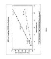
- FIG. 4 illustrates the range of clear apertures versus minimum resolvable feature size.
- the multimodal biometric system 100 includes three imaging systems.
- the first imaging system is a scene imaging system 120 for identifying one or more subjects for biometric identification from a distance.
- the second imaging system is a face imaging system 140 for capturing images of the face 12 of a target subject 10 from a distance.
- the third imaging system is an iris imaging system 160 for capturing images of each iris 14 of the target subject 10 from a distance.
- the imaging systems 120 , 140 , and 160 as well as other components may be housed in a single image capture device, but the components of the biometric system 100 may house the components in any number of combinations and any number of devices.
- the scene imaging system 120 may include one or more cameras that capture images based on photons with visible, near-infrared (NIR), or infrared (IR) wavelengths.
- the visible wavelengths detected may be in a range of approximately 400 nm to 700 nm; the NIR wavelengths detected may be in a range of approximately 700 nm to 2 ⁇ m; and the IR wavelengths detected may be in a range of approximately 2 ⁇ m to 13 ⁇ m.
- the scene imaging system 120 captures images through passive imaging. Passive imaging refers to the detection of photons that are initially emitted from a source external to the biometric system 100 , also referred to as ambient photon generation.
- passive imaging by the scene imaging system 120 may detect photons with visible, NIR, and/or IR wavelengths.
- the biometric system 100 may be used to check subjects attending a large sporting event or similar public gathering, where the ambient lighting at the venue generates a sufficient level of photons with visible wavelengths for detection by the scene imaging system 120 .
- the scene imaging system 120 may detect photons that are provided by an illumination source (not shown) controlled by the biometric system 100 , i.e., active illumination.
- the face imaging system 140 may include a camera that captures images of the face based on photons with visible, NIR, or IR wavelengths.
- the visible wavelengths detected may be in a range of approximately 400 nm to 700 nm; the NIR wavelengths detected may be in a range of approximately 700 nm to 2 ⁇ m; and the IR wavelengths detected may be in a range of approximately 2 ⁇ m to 13 ⁇ m.
- the face imaging system 140 may employ passive imaging to detect photons with visible, NIR, or IR wavelengths.
- the face imaging system 140 may detect photons that are provided by an illumination source controlled by the biometric system 100 , i.e., active illumination.
- the iris imaging system 160 may include a camera that captures iris images based on photons with visible or NIR wavelengths. Photons with visible or NIR wavelengths may be used for iris recognition if the iris sensor is sufficiently large and an adequately high resolution is employed.
- the visible wavelengths detected may have a range of approximately 400 nm to 700 nm.
- the NIR wavelengths detected may be in a range of approximately 700 nm to 2 ⁇ m, or preferably, a range of 700 nm to 900 nm corresponding to the wavelength requirements for the ANSI specification for Iris Image Interchange Format (ANSI INCITS 379-2004).
- the preferable range may generally be determined according to the existing Iris Image Interchange Format standard.
- the iris sensor of the iris imaging system 160 may have a significantly higher magnification than the face sensor of the face imaging system 140 .
- commercially available sensors may be employed, where the sensors, for example, employ 752 ⁇ 480 pixels for each eye image, have a resolution in the range of approximately 16 to 21 pixels/mm, and have a quantum efficiency of approximately 25 to 30 percent at 850 nm illumination.
- the optical design of the iris imaging system 160 may employ a zooming telescope lens having an aperture of 100 mm for 3 m to 6 m.
- telescopes having an aperture of approximately 50 cm to 100 cm for 50 m may be employed.
- the telescope may have a Ritchey-Chrétien design, i.e. a hyperbolic Cassegrain telescope with a very flat field.
- the resolution may be 2 lp/mm to 4 lp/mm, thereby complying with ANSI specifications (ANSI INCITS 379-2004).
- the opto-mechanical requirements may be met with commercially available ultra-high precision axis encoders (resolutions ⁇ 0.002 arc-sec).
- FIG. 3 illustrates the range of clear apertures required to resolve 0.25 mm with 850 nm illumination at varying object distances.
- FIG. 4 illustrates the range of clear apertures versus minimum resolvable feature size, particularly imaging with 850 nm illumination at 50 meters with 5 ⁇ m pixel size.
- One or more illumination systems may be employed for active illumination.
- the illumination system 180 may emit photons with NIR wavelengths which are reflected from the irises 14 of the subject 10 and subsequently detected by iris imaging system 160 .
- such illumination systems may also be used for active imaging by the face imaging system 140 .
- the illumination system 180 may employ an NIR laser source 182 . Filters or coated optics may be employed in the optical train to select specific wavelengths, but still allow a visible color image.
- the illumination system 180 may have a wavelength of approximately 850 nm and a collimated beam with a spot size diameter of approximately 30 cm full width half-maximum (FWHM).
- the laser illumination may be provided with an average power of approximately 1 W and a continuous wave with an irradiance of 2 mW/cm2 or less.
- an optical fiber 184 is coupled to the laser 182 .
- the optical fiber 184 is positioned to direct photons to a rotating diffuser 185 rotating at approximately 1000 revolutions per minute. Rotation of the diffuser 185 helps reduce speckle of the illumination.
- a notch filter 186 may also be placed in line to minimize any visible illumination from the illumination system 180 that may alert people to the presence of the biometric system 100 , especially when the biometric system 100 is intended to be used covertly, i.e. without the subjects' knowledge.
- the illumination expands from the optical fiber 184 and is directed to a mirror 187 .
- the illumination is reflected to a Fresnel lens 188 where it is collimated.
- the beam may be collimated or slightly diverging.
- the laser may be pulsed at 50 nsec with a 10 kHz duty cycle.
- employing a quasi-CW laser reduces laser speckle.
- an optical laser rangefinder 189 with a wavelength, for example, of 904 nm may be used to detect the distance along the Z-axis from the rangefmder 189 to the targeted subject 10 .
- This Z-distance is utilized to improve the accuracy of estimates of the (X, Y, Z) position of the targeted subject 10 as well as to determine the range of focus and zoom, for example, by the iris camera lens of the iris imaging system 160 .
- the Z-distance provides a starting value for a search for an image with the highest focus measure.
- the Z-distance information may also be utilized to predict the anticipated movement of the subject.
- the illumination source 180 may be integrated into a pan-tilt unit (PTU) 195 .
- the PTU 195 may be controlled to direct photons to specific biometric features which are then captured by the iris imaging system 140 and possibly the face imaging system 160 .
- the illumination system 180 may be operated in burst mode triggered in coordination with the respective imaging system 140 or 160 .
- the illumination source 180 may also be employed for range finding to achieve auto focusing by the respective imaging system 140 or 160 , as described previously.
- the PTU 195 may be used to target and track subjects. As shown in FIG. 1 , the illumination system 180 , the camera of face imaging system 140 , the camera of the iris imaging system 160 , and the rangefinder 189 may all be mounted on the single PTU 195 . The camera of the face imaging system 140 , the camera of the iris image system 160 , and the rangefinder 189 are oriented on the PTU 195 so that they receive photons from the illumination source 180 which are reflected from the targeted subject 10 .
- the PTU 195 may be controlled to steer the mounted systems to direct photons from the illumination system 180 and to permit the co-aligned imaging systems 140 or 160 to capture the photons reflected from the respective biometric feature, i.e., face or iris.
- one or more beam steering systems may additionally or alternatively be employed to direct the photons which are detected by the imaging systems 120 , 140 , and 160 for image capture.
- the beam steering systems may include galvanometric mirrors and/or imaging optics positioned on a gimbal mount.
- the beam steering systems may direct photons from the illumination source 180 to a biometric feature of the targeted subject 10 . Additionally or alternatively, the beam steering systems may direct photons reflected from the biometric feature to the appropriate imaging system.
- Embodiments of the present invention meet the safety criteria of Class I ANSI Z136.
- the maximum permissible exposure (MPE) for continuous wave exposure at 850 nm is approximately 2 mW/cm 2 .
- the illumination source 180 in some embodiments may provide illumination with a wavelength of 850 nm for up to 30,000 seconds.
- the maximum permissible exposure (MPE) for repetitive pulse exposure at 850 nm is approximately 0.56 mW/cm 2 .
- the illumination source 180 in other embodiments may provide illumination with a wavelength of 850 nm in a 10 second pulse train with 50 nsec pulses at 10 KHz.
- Other considerations for laser safety include the operational environment, the use of additional optical devices, such as glasses and binoculars, by targeted subjects, as well as the presence of specular surfaces.
- the imaging systems 120 , 140 , and 160 each provide different fields of view.
- FIG. 1 shows that the scene imaging system 120 has the larger field of view 102 .
- the field of view 102 may be several square meters, depending on the distance of subjects from the scene imaging system 120 . Any number of subjects for biometric identification may pass through and/or be positioned within the field of view 102 .
- the heads 6 of subjects 5 are positioned within the field of view 102
- the heads 3 of subjects 2 are positioned outside the field of view 102 .
- FIG. 1 shows a smaller field of view 104 that corresponds with the face imaging system 140 .
- the area of the field of view 104 may be approximately 0.15 m 2 .
- the head 12 of a single targeted subject 10 is isolated within the field of view 102 for further biometric analysis.
- FIG. 1 shows yet a smaller field of view 106 that corresponds with the iris imaging system 160 .
- the field of view 106 defines an area that isolates the irises 14 of the targeted subject 10 for biometric identification.
- the scene imaging system 120 may employ a plurality of scene cameras.
- the cameras may be arranged so that the field of view 102 for each camera overlaps, abuts, or nearly abuts other fields of view 102 , whereby a series of fields of view 102 forms a continuous or nearly continuous a larger 360-degree field of view.
- some embodiments may employ imaging systems which are all co-aligned using beam steering mirrors.
- imaging systems which are all co-aligned using beam steering mirrors.
- the use of a beam steering mirrors may be employed to enable the imaging systems to rotate through 360 degrees for observation.
- some embodiments can identify multiple people within a 360 degree panoramic view.
- Employing such a system may require capturing images in rapid succession from a plurality of subjects who are moving within the panoramic view.
- aspects of these embodiments minimize occlusion of the subject's face and/or irises, minimize the time required to process the captured images, and overcome the constraints associated with the mechanical operation of the system.
- the system 100 may employ at least one controller 190 to control the operation of the imaging systems 120 , 140 , and 160 .
- the controller 190 may also be employed to process the image data captured by the imaging systems 120 , 140 , and 160 .
- the controller 190 may control the operation of the beam steering system 195 , the laser range finder 189 , and the illumination source 180 as a part of a target acquisition system.
- the controller 190 may include one or more programmable processing devices that execute software, or stored instructions.
- the controller 190 may employ an external conventional computer networked with the image systems 120 , 140 , and 160 , as shown in FIG. 1 .
- a field programmable gate array (FPGA) or digital signal processor (DSP) may be employed on board a single image capture device that houses the imaging systems 120 140 , and 160 .
- FPGA field programmable gate array
- DSP digital signal processor
- Combinations of single and/or multiple programmable devices, including computers, FPGAs, and DSPs may be employed with various communications topologies and physical configurations to achieve scalable speed and/or performance targets.
- the multimodal biometric system 100 generates images of the face and two irises for biometric identification.
- the controller 190 may operate the face imaging system 140 to capture an image of the subject's face 12 and the iris imaging system 160 to capture images of each iris 14 from the subject's right and left eyes all simultaneously, or near simultaneously.
- Biometrics based on a combination of facial and iris data are more accurate and robust than using biometrics that include data from only a single iris or only the face. Furthermore, such embodiments exhibit lower fail-to-acquire (FTA) metrics than iris or face only systems and are less susceptible to spoofing.
- FTA fail-to-acquire
- the iris and face present biometric features that are both independent and coupled. They are independent in that they are extracted from different biological structures.
- the iris and face biometric features are strongly coupled because there is a fixed geometric relationship between the iris and the face. Specifically, the position and orientation of an eye is reflected simultaneously in both the iris and the face.
- the coupling between the biometric features of the iris and the face not only facilitates the simultaneous capture of these biometric features, but allows these features to be cross-referenced or combined in a common feature space that preserves the geometric relationship between the iris and face.
- the use of an iris system complements the use of face system.
- an exemplary process 200 for operating the multimodal biometric system 100 is illustrated.
- the system 100 identifies one or more objects, corresponding to the heads 6 of subjects 5 in the field of view 102 .
- the system 100 continuously tracks all objects, which may move within the field of view 102 .
- the system 100 aligns the center of the field of view 104 to one of the objects. As shown in FIG. 1 , the object in the field of view 104 corresponds to the head 6 of the targeted subject 10 .
- the face imaging system 140 which is co-aligned with the scene imaging system 120 , captures an image from the field of view 104 at a sufficiently high magnification and resolution to permit face identification.
- the system 100 identifies the eyes of the face 12 and takes over control of tracking.
- the system 100 adjusts the targeting system to align the face imaging system 140 as well as the NIR illumination source 180 with an area substantially centered on the eyes.
- the rangefmder 189 measures the Z distance of the object and zooms and focuses the iris imaging system 160 .
- the iris imaging system 160 captures images of the irises 14 .
- the iris data is segmented from the images.
- feedback from the iris segmentation may be used to fine tune eye centering if required.
- the segmented iris data is encoded and matched for enrollment or authentication. Authentication may include identifying a subject or verifying a subject's identity.
- the iris imaging system 160 may have one or more iris sensors with higher magnification for capturing images of the irises 14 . As such, the center of the iris sensors are aligned with the eyes and the iris sensors capture the images of the irises 14 .
- step 204 throughout the process 200 , the system 100 continues to track the objects it has identified in the field of view 102 , including the objects which have already been targeted for biometric identification and processed according to steps 206 through 222 . In this way, the system 100 is able to determine which objects still need to be targeted for biometric processing.
- Information captured by the face imaging system 140 and the iris imaging system 160 is used to establish facial pattern recognition, iris pattern recognition, as well as biometric fusion.
- the information from the imaging systems may be used to determine a host of attributes including, but not limited to, positioning of the face or the irises, tracking of the face or irises, measurements of focus provided in the images, and interpupillary distance.
- the software executed by the controller 190 for capturing and processing images of the face 12 and irises 14 may determine characteristics such as linear (X,Y,Z) position of the head, head pose angle, and eye-gaze angle.
- Head pose angle indicates pitch, yaw, and roll, where pitch refers to up-and-down rotation of the head, yaw refers to side-to-side rotation of the head, and roll refers to rotation the head along a direction from ear to shoulder.
- eye-gaze angle refers to the up-and-down or side-to-side viewing angle of the eyes.
- some embodiments may employ a Hartmann-Shack sensor to correct for these environmental factors.
- the software executed by the controller 190 also detects and processes images of the face 12 and irises 14 in the captured data. For instance, as shown in step 218 of FIG. 2 , the images of the irises are segmented from the captured data, and before the segmented iris images are passed on for further biometric processing or matching, the segmented iris images may be tested according to a variety of criteria measuring the quality of an image.
- Such algorithms for processing iris images as well as other relevant algorithms are provided in a U.S. patent application titled MULTIMODAL OCULAR BIOMETRIC SYSTEM AND METHODS, filed on Sep. 10, 2007, which claims priority to U.S. Provisional Application No. 60/844,659 filed Sep. 15, 2006, the contents of all these applications being incorporated entirely herein by reference.
- the iris image data may be employed for biometric matching with databases of existing iris data or may be recorded for biometric enrollment, as shown in step 222 .
- the enrollment may be anonymous, i.e. recorded without further identification data, such as a name.
- embodiments of the present invention may employ various configurations of imaging systems that capture iris images and face images. Although many of the features of embodiments of the present invention may be described with respect to the configuration shown in FIG. 1 , it is understood that other configurations can implement these features in order to combine iris and face images for biometric identification.
- the system can perform facial and iris liveness testing. Facial liveness testing detects whether the biometric information comes from a living source.
- U.S. patent application Ser. No. 11/258,749, filed on Oct. 26, 2005 describes a METHOD AND SYSTEM FOR DETECTING BIOMETRIC LIVENESS, and is entirely incorporated herein by reference.
- embodiments described previously may direct NIR laser illumination over a long distance to the face 12 or the irises 14
- other embodiments may employ use of LED's positioned more closely to the targeted subject.
- LED's may be employed to illuminate a subject as the subject is guided down a specific corridor of known length and width.
- an illumination source may be set up near the known position so that photons for image capture do not have to be transmitted over longer distances.
- Embodiments of the present invention may be fully automatic or may require some operator input, especially with regard to initial targeting of subjects.
- an operator selectively targets subjects for biometric analysis.
- the operator can ensure that the illumination sources are not directed at subjects who may susceptible to eye damage from photons emitted by the illumination sources.
- embodiments of the present invention may be employed to identify and screen subjects at an event, such as a highly attended sporting event. At such events, spectators often use optical aids, such as binoculars, to view the game or match. Eye damage might result if laser illumination is conducted to the eyes of a targeted individual through such an optical aid. As a result, an operator-assisted mode can prevent the laser illumination from being directed at subjects using an optical aid.
- the controller 190 may be a programmable processing device, such as an external conventional computer or an on-board field programmable gate array (FPGA) or digital signal processor (DSP), that executes software, or stored instructions.
- FPGA field programmable gate array
- DSP digital signal processor
- physical processors and/or machines employed by embodiments of the present invention for any processing or evaluation may include one or more networked or non-networked general purpose computer systems, microprocessors, field programmable gate arrays (FPGA's), digital signal processors (DSP's), micro-controllers, and the like, programmed according to the teachings of the exemplary embodiments of the present invention, as is appreciated by those skilled in the computer and software arts.
- the physical processors and/or machines may be externally networked with the image capture device, or may be integrated to reside within the image capture device.
- Appropriate software can be readily prepared by programmers of ordinary skill based on the teachings of the exemplary embodiments, as is appreciated by those skilled in the software art.
- the devices and subsystems of the exemplary embodiments can be implemented by the preparation of application-specific integrated circuits or by interconnecting an appropriate network of conventional component circuits, as is appreciated by those skilled in the electrical art(s).
- the exemplary embodiments are not limited to any specific combination of hardware circuitry and/or software.
- the exemplary embodiments of the present invention may include software for controlling the devices and subsystems of the exemplary embodiments, for driving the devices and subsystems of the exemplary embodiments, for enabling the devices and subsystems of the exemplary embodiments to interact with a human user, and the like.
- software can include, but is not limited to, device drivers, firmware, operating systems, development tools, applications software, and the like.
- Such computer readable media further can include the computer program product of an embodiment of the present inventions for performing all or a portion (if processing is distributed) of the processing performed in implementing the inventions.
- Computer code devices of the exemplary embodiments of the present inventions can include any suitable interpretable or executable code mechanism, including but not limited to scripts, interpretable programs, dynamic link libraries (DLLs), Java classes and applets, complete executable programs, and the like. Moreover, parts of the processing of the exemplary embodiment of the present inventions can be distributed for better performance, reliability, cost, and the like.
- interpretable or executable code mechanism including but not limited to scripts, interpretable programs, dynamic link libraries (DLLs), Java classes and applets, complete executable programs, and the like.
- Computer-readable media may include, for example, a floppy disk, a flexible disk, hard disk, magnetic tape, any other suitable magnetic medium, a CD-ROM, CDRW, DVD, any other suitable optical medium, punch cards, paper tape, optical mark sheets, any other suitable physical medium with patterns of holes or other optically recognizable indicia, a RAM, a PROM, an EPROM, a FLASH-EPROM, any other suitable memory chip or cartridge, a carrier wave or any other suitable medium from which a computer can read.
- a floppy disk a flexible disk, hard disk, magnetic tape, any other suitable magnetic medium, a CD-ROM, CDRW, DVD, any other suitable optical medium, punch cards, paper tape, optical mark sheets, any other suitable physical medium with patterns of holes or other optically recognizable indicia, a RAM, a PROM, an EPROM, a FLASH-EPROM, any other suitable memory chip or cartridge, a carrier wave or any other suitable medium from which a computer can read.
Abstract
Description
Claims (27)
Priority Applications (5)
| Application Number | Priority Date | Filing Date | Title |
|---|---|---|---|
| US11/898,188 US8433103B2 (en) | 2006-09-15 | 2007-09-10 | Long distance multimodal biometric system and method |
| PCT/US2008/075910 WO2009036103A1 (en) | 2007-09-10 | 2008-09-10 | Long distance multimodal biometric system and method |
| US12/208,328 US8121356B2 (en) | 2006-09-15 | 2008-09-10 | Long distance multimodal biometric system and method |
| EP08830286.4A EP2198391A4 (en) | 2007-09-10 | 2008-09-10 | Long distance multimodal biometric system and method |
| US13/400,499 US8577093B2 (en) | 2006-09-15 | 2012-02-20 | Long distance multimodal biometric system and method |
Applications Claiming Priority (2)
| Application Number | Priority Date | Filing Date | Title |
|---|---|---|---|
| US84464406P | 2006-09-15 | 2006-09-15 | |
| US11/898,188 US8433103B2 (en) | 2006-09-15 | 2007-09-10 | Long distance multimodal biometric system and method |
Related Child Applications (1)
| Application Number | Title | Priority Date | Filing Date |
|---|---|---|---|
| US12/208,328 Continuation-In-Part US8121356B2 (en) | 2006-09-15 | 2008-09-10 | Long distance multimodal biometric system and method |
Publications (2)
| Publication Number | Publication Date |
|---|---|
| US20080069411A1 US20080069411A1 (en) | 2008-03-20 |
| US8433103B2 true US8433103B2 (en) | 2013-04-30 |
Family
ID=39184488
Family Applications (1)
| Application Number | Title | Priority Date | Filing Date |
|---|---|---|---|
| US11/898,188 Expired - Fee Related US8433103B2 (en) | 2006-09-15 | 2007-09-10 | Long distance multimodal biometric system and method |
Country Status (3)
| Country | Link |
|---|---|
| US (1) | US8433103B2 (en) |
| EP (1) | EP2062197A4 (en) |
| WO (1) | WO2008033784A2 (en) |
Cited By (9)
| Publication number | Priority date | Publication date | Assignee | Title |
|---|---|---|---|---|
| US20140119617A1 (en) * | 2012-10-26 | 2014-05-01 | Oberthur Technologies | Biometric identification |
| US20150067801A1 (en) * | 2007-06-15 | 2015-03-05 | Microsoft Corporation | Multiple user authentications on a communications device |
| US10102419B2 (en) * | 2015-10-30 | 2018-10-16 | Intel Corporation | Progressive radar assisted facial recognition |
| WO2018224882A1 (en) * | 2017-06-06 | 2018-12-13 | Global Bionic Optics Limited | Blended iris and facial biometric system |
| US10157312B2 (en) | 2015-10-08 | 2018-12-18 | Microsoft Technology Licensing, Llc | Iris recognition |
| US10445606B2 (en) | 2015-10-08 | 2019-10-15 | Microsoft Technology Licensing, Llc | Iris recognition |
| US11205071B2 (en) * | 2018-07-16 | 2021-12-21 | Advanced New Technologies Co., Ltd. | Image acquisition method, apparatus, system, and electronic device |
| US20220139110A1 (en) * | 2019-02-18 | 2022-05-05 | Nec Corporation | Image pick-up apparatus, method, system, and computer readable medium |
| US11816198B2 (en) | 2021-04-06 | 2023-11-14 | Bank Of America Corporation | Systems and methods for geolocation security using biometric analysis |
Families Citing this family (28)
| Publication number | Priority date | Publication date | Assignee | Title |
|---|---|---|---|---|
| US20090177398A1 (en) * | 2008-01-08 | 2009-07-09 | Trex Enterprises Corp. | Angles only navigation system |
| US8351659B2 (en) * | 2007-06-14 | 2013-01-08 | Cubic Corporation | Eye detection system |
| US8737703B2 (en) * | 2008-01-16 | 2014-05-27 | The Charles Stark Draper Laboratory, Inc. | Systems and methods for detecting retinal abnormalities |
| US8718363B2 (en) * | 2008-01-16 | 2014-05-06 | The Charles Stark Draper Laboratory, Inc. | Systems and methods for analyzing image data using adaptive neighborhooding |
| FR2935498B1 (en) * | 2008-08-27 | 2010-10-15 | Eads Europ Aeronautic Defence | METHOD FOR IDENTIFYING AN OBJECT IN A VIDEO ARCHIVE |
| WO2012011181A1 (en) * | 2010-07-22 | 2012-01-26 | 富士通株式会社 | Vein image capturing device |
| US20120213417A1 (en) * | 2011-02-16 | 2012-08-23 | Ideal Innovations Incorporated | Biometric Electronic Skimming Station |
| WO2013056001A1 (en) * | 2011-10-12 | 2013-04-18 | Carnegie Mellon University | System and method for the long range acquisition of iris images for stationary and mobile subjects |
| CN105095845A (en) * | 2014-05-22 | 2015-11-25 | 宁波舜宇光电信息有限公司 | Iris and face identification system as well as application and method thereof |
| WO2016049273A1 (en) | 2014-09-24 | 2016-03-31 | Sri International | Control of wireless communication device capability in a mobile device with a biometric key |
| KR102305997B1 (en) * | 2014-11-17 | 2021-09-28 | 엘지이노텍 주식회사 | Iris recognition camera system, terminal including the same and iris recognition method using the system |
| JP2018506872A (en) | 2014-12-03 | 2018-03-08 | プリンストン・アイデンティティー・インコーポレーテッド | System and method for mobile device biometric add-on |
| CN106295270B (en) * | 2015-06-25 | 2019-03-29 | 联想(北京)有限公司 | A kind of user identification method and electronic equipment |
| AU2016310452B2 (en) | 2015-08-21 | 2021-04-22 | Magic Leap, Inc. | Eyelid shape estimation |
| KR20230150397A (en) | 2015-08-21 | 2023-10-30 | 매직 립, 인코포레이티드 | Eyelid shape estimation using eye pose measurement |
| NZ741863A (en) * | 2015-10-16 | 2019-05-31 | Magic Leap Inc | Eye pose identification using eye features |
| JP2019506694A (en) | 2016-01-12 | 2019-03-07 | プリンストン・アイデンティティー・インコーポレーテッド | Biometric analysis system and method |
| US10366296B2 (en) | 2016-03-31 | 2019-07-30 | Princeton Identity, Inc. | Biometric enrollment systems and methods |
| WO2017172695A1 (en) * | 2016-03-31 | 2017-10-05 | Princeton Identity, Inc. | Systems and methods of biometric anaysis with adaptive trigger |
| US9638800B1 (en) | 2016-11-22 | 2017-05-02 | 4Sense, Inc. | Passive tracking system |
| US9720086B1 (en) | 2016-11-22 | 2017-08-01 | 4Sense, Inc. | Thermal- and modulated-light-based passive tracking system |
| US20180189547A1 (en) * | 2016-12-30 | 2018-07-05 | Intel Corporation | Biometric identification system |
| WO2018187337A1 (en) | 2017-04-04 | 2018-10-11 | Princeton Identity, Inc. | Z-dimension user feedback biometric system |
| CN107368775A (en) * | 2017-04-21 | 2017-11-21 | 阿里巴巴集团控股有限公司 | Method for previewing and device during a kind of iris recognition |
| KR102573482B1 (en) | 2017-07-26 | 2023-08-31 | 프린스톤 아이덴티티, 인크. | Biometric security system and method |
| CN107517339A (en) * | 2017-09-05 | 2017-12-26 | 信利光电股份有限公司 | A kind of camera module and electronic equipment |
| US10728447B2 (en) * | 2018-10-26 | 2020-07-28 | Alibaba Group Holding Limited | Capturing images using sub-frame illumination |
| US11403884B2 (en) * | 2019-01-16 | 2022-08-02 | Shenzhen GOODIX Technology Co., Ltd. | Anti-spoofing face ID sensing |
Citations (63)
| Publication number | Priority date | Publication date | Assignee | Title |
|---|---|---|---|---|
| US3069654A (en) | 1960-03-25 | 1962-12-18 | Paul V C Hough | Method and means for recognizing complex patterns |
| US4641349A (en) | 1985-02-20 | 1987-02-03 | Leonard Flom | Iris recognition system |
| US5291560A (en) | 1991-07-15 | 1994-03-01 | Iri Scan Incorporated | Biometric personal identification system based on iris analysis |
| US5572596A (en) | 1994-09-02 | 1996-11-05 | David Sarnoff Research Center, Inc. | Automated, non-invasive iris recognition system and method |
| US5836872A (en) | 1989-04-13 | 1998-11-17 | Vanguard Imaging, Ltd. | Digital optical visualization, enhancement, quantification, and classification of surface and subsurface features of body surfaces |
| US5850470A (en) * | 1995-08-30 | 1998-12-15 | Siemens Corporate Research, Inc. | Neural network for locating and recognizing a deformable object |
| US5859686A (en) | 1997-05-19 | 1999-01-12 | Northrop Grumman Corporation | Eye finding and tracking system |
| US5953440A (en) | 1997-12-02 | 1999-09-14 | Sensar, Inc. | Method of measuring the focus of close-up images of eyes |
| US6011624A (en) * | 1998-01-06 | 2000-01-04 | Zygo Corporation | Geometrically-Desensitized interferometer with adjustable range of measurement depths |
| US6144754A (en) | 1997-03-28 | 2000-11-07 | Oki Electric Industry Co., Ltd. | Method and apparatus for identifying individuals |
| US6152563A (en) | 1998-02-20 | 2000-11-28 | Hutchinson; Thomas E. | Eye gaze direction tracker |
| US6215891B1 (en) | 1997-03-26 | 2001-04-10 | Oki Electric Industry Co., Ltd. | Eye image recognition method eye image selection method and system therefor |
| US6247813B1 (en) | 1999-04-09 | 2001-06-19 | Iritech, Inc. | Iris identification system and method of identifying a person through iris recognition |
| US6285780B1 (en) | 1997-03-28 | 2001-09-04 | Oki Electric Industry Co., Ltd. | Apparatus for identifying individual animals and image processing method |
| US6373968B2 (en) | 1997-06-06 | 2002-04-16 | Oki Electric Industry Co., Ltd. | System for identifying individuals |
| US6442465B2 (en) * | 1992-05-05 | 2002-08-27 | Automotive Technologies International, Inc. | Vehicular component control systems and methods |
| US20020136435A1 (en) * | 2001-03-26 | 2002-09-26 | Prokoski Francine J. | Dual band biometric identification system |
| US20030012413A1 (en) | 2001-07-16 | 2003-01-16 | Matsushita Electric Industrial Co., Ltd. | Iris identification apparatus and iris image pickup apparatus |
| US6526160B1 (en) | 1998-07-17 | 2003-02-25 | Media Technology Corporation | Iris information acquisition apparatus and iris identification apparatus |
| US6529630B1 (en) | 1998-03-02 | 2003-03-04 | Fuji Photo Film Co., Ltd. | Method and device for extracting principal image subjects |
| US6532298B1 (en) * | 1998-11-25 | 2003-03-11 | Iridian Technologies, Inc. | Portable authentication device and method using iris patterns |
| US6542624B1 (en) | 1998-07-17 | 2003-04-01 | Oki Electric Industry Co., Ltd. | Iris code generating device and iris identifying system |
| US6546121B1 (en) | 1998-03-05 | 2003-04-08 | Oki Electric Industry Co., Ltd. | Method and apparatus for identifying an iris |
| US6571002B1 (en) | 1999-05-13 | 2003-05-27 | Mitsubishi Denki Kabushiki Kaisha | Eye open/close detection through correlation |
| US20030108224A1 (en) * | 2001-05-11 | 2003-06-12 | Takahiro Ike | Authentication object image-pickup method and device therefor |
| US20030118217A1 (en) * | 2000-08-09 | 2003-06-26 | Kenji Kondo | Eye position detection method and device |
| US6591064B2 (en) | 2001-07-24 | 2003-07-08 | Matsushita Electric Industrial Co., Ltd. | Iris pickup apparatus |
| US6597377B1 (en) | 1997-02-25 | 2003-07-22 | International Business Machines Corporation | Web links objects |
| US6614919B1 (en) | 1998-12-25 | 2003-09-02 | Oki Electric Industry Co., Ltd. | Method of extracting iris region and individual identification device |
| US6700998B1 (en) | 1999-04-23 | 2004-03-02 | Oki Electric Industry Co, Ltd. | Iris registration unit |
| US6714665B1 (en) | 1994-09-02 | 2004-03-30 | Sarnoff Corporation | Fully automated iris recognition system utilizing wide and narrow fields of view |
| US6753919B1 (en) | 1998-11-25 | 2004-06-22 | Iridian Technologies, Inc. | Fast focus assessment system and method for imaging |
| US6760467B1 (en) | 1999-03-23 | 2004-07-06 | Lg Electronics Inc. | Falsification discrimination method for iris recognition system |
| US6778698B1 (en) | 1999-06-11 | 2004-08-17 | Pts Corporation | Method and apparatus for digital image segmentation |
| US6785406B1 (en) | 1999-07-19 | 2004-08-31 | Sony Corporation | Iris authentication apparatus |
| US20040197011A1 (en) | 2003-04-04 | 2004-10-07 | Camus Theodore A. | Method and apparatus for providing a robust object finder |
| WO2005008567A1 (en) | 2003-07-18 | 2005-01-27 | Yonsei University | Apparatus and method for iris recognition from all direction of view |
| US6850631B1 (en) | 1998-02-20 | 2005-02-01 | Oki Electric Industry Co., Ltd. | Photographing device, iris input device and iris image input method |
| US20050078868A1 (en) | 2003-09-26 | 2005-04-14 | William Chen | Method and apparatus for summarizing and indexing the contents of an audio-visual presentation |
| US20050084179A1 (en) | 2003-09-04 | 2005-04-21 | Keith Hanna | Method and apparatus for performing iris recognition from an image |
| US6944318B1 (en) | 1999-01-15 | 2005-09-13 | Citicorp Development Center, Inc. | Fast matching systems and methods for personal identification |
| US20050251347A1 (en) | 2004-05-05 | 2005-11-10 | Pietro Perona | Automatic visual recognition of biological particles |
| US20060008124A1 (en) | 2004-07-12 | 2006-01-12 | Ewe Hong T | Iris image-based recognition system |
| US6992717B2 (en) | 2000-09-18 | 2006-01-31 | Oki Electric Industry Co., Ltd. | Iris identifying apparatus |
| US20060140454A1 (en) * | 2004-12-07 | 2006-06-29 | Northcott Malcolm J | Iris imaging using reflection from the eye |
| US20060140453A1 (en) * | 2003-01-31 | 2006-06-29 | Geng Z J | Three-dimensional ear biometrics system and method |
| US20060147094A1 (en) | 2003-09-08 | 2006-07-06 | Woong-Tuk Yoo | Pupil detection method and shape descriptor extraction method for a iris recognition, iris feature extraction apparatus and method, and iris recognition system and method using its |
| US20060165266A1 (en) | 2005-01-26 | 2006-07-27 | Honeywell International Inc. | Iris recognition system and method |
| US20060187305A1 (en) * | 2002-07-01 | 2006-08-24 | Trivedi Mohan M | Digital processing of video images |
| US7099495B2 (en) | 2001-02-28 | 2006-08-29 | Matsushita Electric Industrial Co., Ltd. | Frequency and resolution analyzed biometric authentication method and device |
| US20060228005A1 (en) * | 2005-04-08 | 2006-10-12 | Canon Kabushiki Kaisha | Information processing apparatus and information processing method |
| US7155035B2 (en) | 2002-02-05 | 2006-12-26 | Matsushita Electric Industrial Co., Ltd. | Personal authentication method, personal authentication apparatus and image capturing device |
| US20070036397A1 (en) | 2005-01-26 | 2007-02-15 | Honeywell International Inc. | A distance iris recognition |
| US20070047773A1 (en) | 2005-08-31 | 2007-03-01 | Stmicroelectronics S.A. | Digital processing of an iris image |
| US20070047772A1 (en) | 2005-08-25 | 2007-03-01 | Matey James R | Methods and systems for biometric identification |
| US7197166B2 (en) | 2003-01-23 | 2007-03-27 | Industrial Technology Research Institute | Iris extraction method capable of precisely determining positions and sizes of irises in a digital face image |
| US20070110284A1 (en) | 2003-12-18 | 2007-05-17 | Rieul Francois | Method and apparatus for iris recognition |
| US20070160267A1 (en) | 2006-01-11 | 2007-07-12 | Jones Michael J | Method for localizing irises in images using gradients and textures |
| US20070160266A1 (en) | 2006-01-11 | 2007-07-12 | Jones Michael J | Method for extracting features of irises in images using difference of sum filters |
| US7277561B2 (en) | 2000-10-07 | 2007-10-02 | Qritek Co., Ltd. | Iris identification |
| US7362884B2 (en) * | 2005-03-17 | 2008-04-22 | Imageware Systems, Inc. | Multimodal biometric analysis |
| US7697734B2 (en) * | 2005-11-19 | 2010-04-13 | Electronics And Telecommunications Research Institute | Method and apparatus of detecting eye using symmetry and moment characteristics of object |
| US8064647B2 (en) * | 2006-03-03 | 2011-11-22 | Honeywell International Inc. | System for iris detection tracking and recognition at a distance |
Family Cites Families (4)
| Publication number | Priority date | Publication date | Assignee | Title |
|---|---|---|---|---|
| IT1230289B (en) * | 1989-06-15 | 1991-10-18 | Sgs Thomson Microelectronics | PROTECTION DEVICE AGAINST OVERVOLTAGES FOR INTEGRATED ELECTRONIC CIRCUITS, IN PARTICULAR FOR AUTOMOTIVE FIELD APPLICATIONS. |
| US6526161B1 (en) * | 1999-08-30 | 2003-02-25 | Koninklijke Philips Electronics N.V. | System and method for biometrics-based facial feature extraction |
| JP2003037766A (en) * | 2001-07-24 | 2003-02-07 | Matsushita Electric Ind Co Ltd | Iris imager |
| US8299979B2 (en) * | 2003-05-14 | 2012-10-30 | Broadcom Corporation | Integral eye-path alignment on telephony and computer video devices using two or more image sensing devices |
-
2007
- 2007-09-10 WO PCT/US2007/078074 patent/WO2008033784A2/en active Application Filing
- 2007-09-10 US US11/898,188 patent/US8433103B2/en not_active Expired - Fee Related
- 2007-09-10 EP EP20070842181 patent/EP2062197A4/en not_active Ceased
Patent Citations (69)
| Publication number | Priority date | Publication date | Assignee | Title |
|---|---|---|---|---|
| US3069654A (en) | 1960-03-25 | 1962-12-18 | Paul V C Hough | Method and means for recognizing complex patterns |
| US4641349A (en) | 1985-02-20 | 1987-02-03 | Leonard Flom | Iris recognition system |
| US5836872A (en) | 1989-04-13 | 1998-11-17 | Vanguard Imaging, Ltd. | Digital optical visualization, enhancement, quantification, and classification of surface and subsurface features of body surfaces |
| US5291560A (en) | 1991-07-15 | 1994-03-01 | Iri Scan Incorporated | Biometric personal identification system based on iris analysis |
| US6442465B2 (en) * | 1992-05-05 | 2002-08-27 | Automotive Technologies International, Inc. | Vehicular component control systems and methods |
| US5572596A (en) | 1994-09-02 | 1996-11-05 | David Sarnoff Research Center, Inc. | Automated, non-invasive iris recognition system and method |
| US5751836A (en) | 1994-09-02 | 1998-05-12 | David Sarnoff Research Center Inc. | Automated, non-invasive iris recognition system and method |
| US6714665B1 (en) | 1994-09-02 | 2004-03-30 | Sarnoff Corporation | Fully automated iris recognition system utilizing wide and narrow fields of view |
| US5850470A (en) * | 1995-08-30 | 1998-12-15 | Siemens Corporate Research, Inc. | Neural network for locating and recognizing a deformable object |
| US6597377B1 (en) | 1997-02-25 | 2003-07-22 | International Business Machines Corporation | Web links objects |
| US6215891B1 (en) | 1997-03-26 | 2001-04-10 | Oki Electric Industry Co., Ltd. | Eye image recognition method eye image selection method and system therefor |
| US6144754A (en) | 1997-03-28 | 2000-11-07 | Oki Electric Industry Co., Ltd. | Method and apparatus for identifying individuals |
| US6229907B1 (en) | 1997-03-28 | 2001-05-08 | Oki Electric Industry Co., Ltd. | Method and apparatus for identifying individual |
| US6285780B1 (en) | 1997-03-28 | 2001-09-04 | Oki Electric Industry Co., Ltd. | Apparatus for identifying individual animals and image processing method |
| US5859686A (en) | 1997-05-19 | 1999-01-12 | Northrop Grumman Corporation | Eye finding and tracking system |
| US6373968B2 (en) | 1997-06-06 | 2002-04-16 | Oki Electric Industry Co., Ltd. | System for identifying individuals |
| US5953440A (en) | 1997-12-02 | 1999-09-14 | Sensar, Inc. | Method of measuring the focus of close-up images of eyes |
| US6011624A (en) * | 1998-01-06 | 2000-01-04 | Zygo Corporation | Geometrically-Desensitized interferometer with adjustable range of measurement depths |
| US6152563A (en) | 1998-02-20 | 2000-11-28 | Hutchinson; Thomas E. | Eye gaze direction tracker |
| US6850631B1 (en) | 1998-02-20 | 2005-02-01 | Oki Electric Industry Co., Ltd. | Photographing device, iris input device and iris image input method |
| US6529630B1 (en) | 1998-03-02 | 2003-03-04 | Fuji Photo Film Co., Ltd. | Method and device for extracting principal image subjects |
| US6546121B1 (en) | 1998-03-05 | 2003-04-08 | Oki Electric Industry Co., Ltd. | Method and apparatus for identifying an iris |
| US6526160B1 (en) | 1998-07-17 | 2003-02-25 | Media Technology Corporation | Iris information acquisition apparatus and iris identification apparatus |
| US6542624B1 (en) | 1998-07-17 | 2003-04-01 | Oki Electric Industry Co., Ltd. | Iris code generating device and iris identifying system |
| US6532298B1 (en) * | 1998-11-25 | 2003-03-11 | Iridian Technologies, Inc. | Portable authentication device and method using iris patterns |
| US6753919B1 (en) | 1998-11-25 | 2004-06-22 | Iridian Technologies, Inc. | Fast focus assessment system and method for imaging |
| US6614919B1 (en) | 1998-12-25 | 2003-09-02 | Oki Electric Industry Co., Ltd. | Method of extracting iris region and individual identification device |
| US6944318B1 (en) | 1999-01-15 | 2005-09-13 | Citicorp Development Center, Inc. | Fast matching systems and methods for personal identification |
| US6760467B1 (en) | 1999-03-23 | 2004-07-06 | Lg Electronics Inc. | Falsification discrimination method for iris recognition system |
| US6247813B1 (en) | 1999-04-09 | 2001-06-19 | Iritech, Inc. | Iris identification system and method of identifying a person through iris recognition |
| US6700998B1 (en) | 1999-04-23 | 2004-03-02 | Oki Electric Industry Co, Ltd. | Iris registration unit |
| US6571002B1 (en) | 1999-05-13 | 2003-05-27 | Mitsubishi Denki Kabushiki Kaisha | Eye open/close detection through correlation |
| US6778698B1 (en) | 1999-06-11 | 2004-08-17 | Pts Corporation | Method and apparatus for digital image segmentation |
| US6785406B1 (en) | 1999-07-19 | 2004-08-31 | Sony Corporation | Iris authentication apparatus |
| US7130453B2 (en) | 2000-08-09 | 2006-10-31 | Matsushita Electric Industrial Co., Ltd. | Eye position detection method and device |
| US20030118217A1 (en) * | 2000-08-09 | 2003-06-26 | Kenji Kondo | Eye position detection method and device |
| US6992717B2 (en) | 2000-09-18 | 2006-01-31 | Oki Electric Industry Co., Ltd. | Iris identifying apparatus |
| US7277561B2 (en) | 2000-10-07 | 2007-10-02 | Qritek Co., Ltd. | Iris identification |
| US7099495B2 (en) | 2001-02-28 | 2006-08-29 | Matsushita Electric Industrial Co., Ltd. | Frequency and resolution analyzed biometric authentication method and device |
| US20020136435A1 (en) * | 2001-03-26 | 2002-09-26 | Prokoski Francine J. | Dual band biometric identification system |
| US20030108224A1 (en) * | 2001-05-11 | 2003-06-12 | Takahiro Ike | Authentication object image-pickup method and device therefor |
| US20030012413A1 (en) | 2001-07-16 | 2003-01-16 | Matsushita Electric Industrial Co., Ltd. | Iris identification apparatus and iris image pickup apparatus |
| US6591064B2 (en) | 2001-07-24 | 2003-07-08 | Matsushita Electric Industrial Co., Ltd. | Iris pickup apparatus |
| US7155035B2 (en) | 2002-02-05 | 2006-12-26 | Matsushita Electric Industrial Co., Ltd. | Personal authentication method, personal authentication apparatus and image capturing device |
| US20060187305A1 (en) * | 2002-07-01 | 2006-08-24 | Trivedi Mohan M | Digital processing of video images |
| US7197166B2 (en) | 2003-01-23 | 2007-03-27 | Industrial Technology Research Institute | Iris extraction method capable of precisely determining positions and sizes of irises in a digital face image |
| US20060140453A1 (en) * | 2003-01-31 | 2006-06-29 | Geng Z J | Three-dimensional ear biometrics system and method |
| US7599524B2 (en) | 2003-04-04 | 2009-10-06 | Sarnoff Corporation | Method and apparatus for providing a robust object finder |
| US20040197011A1 (en) | 2003-04-04 | 2004-10-07 | Camus Theodore A. | Method and apparatus for providing a robust object finder |
| WO2005008567A1 (en) | 2003-07-18 | 2005-01-27 | Yonsei University | Apparatus and method for iris recognition from all direction of view |
| US20050084179A1 (en) | 2003-09-04 | 2005-04-21 | Keith Hanna | Method and apparatus for performing iris recognition from an image |
| US20060147094A1 (en) | 2003-09-08 | 2006-07-06 | Woong-Tuk Yoo | Pupil detection method and shape descriptor extraction method for a iris recognition, iris feature extraction apparatus and method, and iris recognition system and method using its |
| US20050078868A1 (en) | 2003-09-26 | 2005-04-14 | William Chen | Method and apparatus for summarizing and indexing the contents of an audio-visual presentation |
| US20070110284A1 (en) | 2003-12-18 | 2007-05-17 | Rieul Francois | Method and apparatus for iris recognition |
| US20050251347A1 (en) | 2004-05-05 | 2005-11-10 | Pietro Perona | Automatic visual recognition of biological particles |
| US20060008124A1 (en) | 2004-07-12 | 2006-01-12 | Ewe Hong T | Iris image-based recognition system |
| US20060140454A1 (en) * | 2004-12-07 | 2006-06-29 | Northcott Malcolm J | Iris imaging using reflection from the eye |
| US20070036397A1 (en) | 2005-01-26 | 2007-02-15 | Honeywell International Inc. | A distance iris recognition |
| US20060165266A1 (en) | 2005-01-26 | 2006-07-27 | Honeywell International Inc. | Iris recognition system and method |
| US7593550B2 (en) | 2005-01-26 | 2009-09-22 | Honeywell International Inc. | Distance iris recognition |
| US7362884B2 (en) * | 2005-03-17 | 2008-04-22 | Imageware Systems, Inc. | Multimodal biometric analysis |
| US20060228005A1 (en) * | 2005-04-08 | 2006-10-12 | Canon Kabushiki Kaisha | Information processing apparatus and information processing method |
| US20070047772A1 (en) | 2005-08-25 | 2007-03-01 | Matey James R | Methods and systems for biometric identification |
| US20070047773A1 (en) | 2005-08-31 | 2007-03-01 | Stmicroelectronics S.A. | Digital processing of an iris image |
| US7697734B2 (en) * | 2005-11-19 | 2010-04-13 | Electronics And Telecommunications Research Institute | Method and apparatus of detecting eye using symmetry and moment characteristics of object |
| US20070160266A1 (en) | 2006-01-11 | 2007-07-12 | Jones Michael J | Method for extracting features of irises in images using difference of sum filters |
| US7583823B2 (en) | 2006-01-11 | 2009-09-01 | Mitsubishi Electric Research Laboratories, Inc. | Method for localizing irises in images using gradients and textures |
| US20070160267A1 (en) | 2006-01-11 | 2007-07-12 | Jones Michael J | Method for localizing irises in images using gradients and textures |
| US8064647B2 (en) * | 2006-03-03 | 2011-11-22 | Honeywell International Inc. | System for iris detection tracking and recognition at a distance |
Non-Patent Citations (17)
| Title |
|---|
| Basit, A. et al. "A Fast and Robust Iris Localization Method." IADIS International Conference Applied Computing, Feb. 25-28, 2006 (pp. 557-560). |
| Camus, T. et al. "Reliable and Fast Eye Finding in Close-up Images." Proceedings of the 16th International Conference on Pattern Recognition. vol. 1, 2002 (pp. 389-394). |
| Christel-Loic Tisse, et al.; "Person identification technique using human iris recognition"; Advanced System Technology; Universite de Montpellier. |
| European Search Report corresponding to European patent Application Serial No. 07 84 2181, European Patent Office, dated Aug. 27, 2010, 7 pages. |
| Fancourt et al.; "Iris Recognition at a Distance"; Audio- and Video-based Biometric Person Authentication; (Lecture Notes in Computer Science;; LNCS), Springer-Verlag, Berlin/Heidelberg, pp. 1-13; XP019013243; ISBN: 978-3-540-27887-0; Jun. 28, 2005. |
| Guo et al., "A System for Automatic Iris Capturing", Mitsubishi Electric Research Laboratories, TR2005-044, 2005. * |
| International Search Report for PCT/US08/75910, dated Nov. 28, 2008, 3 pages. |
| Libor Masek; "Recognition of Human Iris Patterns for Biometric Identification"; School of Computer Science and Software Engineering, The University of Western Australia, 2003, pp. 1-56. |
| Liu, X. et al. "Experiments with an Improved Iris Segmentation Algorithm." Fourth IEEE Workshop on Automatic Identification Advanced Technologies, Oct. 2005 (6 pages). |
| Nobuyuki Otsu; "A Threshold Selection Method from Gray-Level Histograms"; IEEE Transactions on Systems Man and Cybernetics, vol. SMC-9, No. I, Jan. 1979. |
| Ping-Sung Liao, et al.; "A Fast Algorithm for Multilevel Thresholding"; Journal of Information Science and Engineering 17, pp. 713-727 (2001). |
| Ross et al.; "Handbook of Multibiometrics"; Springer Science, New York, US XP002597965 ISBN: 978-0-387-22296-7; p. 51; Jun. 24, 2006. |
| Vezhnevets, V. et al. "Robust and Accurate Eye Contour Extraction." International Conference Graphicon, 2003 (4 pages). |
| Wang et al., "Combining Face and Iris Biometrics for Identity Verification", Proceedings of Fourth International Conference on AVBPA, Guildford, UK, 2003, pp. 805-813. * |
| Written Opinion for PCT/US08/75910, dated Nov. 28, 2008, 9 pages. |
| Xiaomei Liu, et al.; "Experiments with an Improved Iris Segmentation Algorithm"; Department of Computer Science and Engineering University of Notre Dame; Fourth IEEE Workshop on Automatic Identification Advanced Technologies (AutolD), Oct. 2005, New York, 6 pages. |
| Y. Park, et al.; "A Fast Circular Edge Detector for the Iris Region Segmentation"; S.-W. Lee, H.H. Buelthoff, T. Poggio (Eds.) BMCV 2000, LNCS 1811, pp. 417-423, 2000. |
Cited By (14)
| Publication number | Priority date | Publication date | Assignee | Title |
|---|---|---|---|---|
| US20150067801A1 (en) * | 2007-06-15 | 2015-03-05 | Microsoft Corporation | Multiple user authentications on a communications device |
| US9497191B2 (en) * | 2007-06-15 | 2016-11-15 | Microsoft Technology Licensing, Llc | Multiple user authentications on a communications device |
| US20140119617A1 (en) * | 2012-10-26 | 2014-05-01 | Oberthur Technologies | Biometric identification |
| US9224057B2 (en) * | 2012-10-26 | 2015-12-29 | Oberthur Technologies | Biometric identification |
| US10157312B2 (en) | 2015-10-08 | 2018-12-18 | Microsoft Technology Licensing, Llc | Iris recognition |
| US10445606B2 (en) | 2015-10-08 | 2019-10-15 | Microsoft Technology Licensing, Llc | Iris recognition |
| US10102419B2 (en) * | 2015-10-30 | 2018-10-16 | Intel Corporation | Progressive radar assisted facial recognition |
| WO2018224882A1 (en) * | 2017-06-06 | 2018-12-13 | Global Bionic Optics Limited | Blended iris and facial biometric system |
| US10430644B2 (en) | 2017-06-06 | 2019-10-01 | Global Bionic Optics Ltd. | Blended iris and facial biometric system |
| US11205071B2 (en) * | 2018-07-16 | 2021-12-21 | Advanced New Technologies Co., Ltd. | Image acquisition method, apparatus, system, and electronic device |
| US11244158B2 (en) * | 2018-07-16 | 2022-02-08 | Advanced New Technologies Co., Ltd. | Image acquisition method, apparatus, system, and electronic device |
| US20220139110A1 (en) * | 2019-02-18 | 2022-05-05 | Nec Corporation | Image pick-up apparatus, method, system, and computer readable medium |
| US11935328B2 (en) * | 2019-02-18 | 2024-03-19 | Nec Corporation | Image pick-up apparatus, method, system, and computer readable medium |
| US11816198B2 (en) | 2021-04-06 | 2023-11-14 | Bank Of America Corporation | Systems and methods for geolocation security using biometric analysis |
Also Published As
| Publication number | Publication date |
|---|---|
| EP2062197A2 (en) | 2009-05-27 |
| WO2008033784A2 (en) | 2008-03-20 |
| US20080069411A1 (en) | 2008-03-20 |
| WO2008033784A3 (en) | 2008-10-02 |
| EP2062197A4 (en) | 2010-10-06 |
Similar Documents
| Publication | Publication Date | Title |
|---|---|---|
| US8433103B2 (en) | Long distance multimodal biometric system and method | |
| US8577093B2 (en) | Long distance multimodal biometric system and method | |
| US10395097B2 (en) | Method and system for biometric recognition | |
| US7271839B2 (en) | Display device of focal angle and focal distance in iris recognition system | |
| US5956122A (en) | Iris recognition apparatus and method | |
| US7428320B2 (en) | Iris imaging using reflection from the eye | |
| US7095901B2 (en) | Apparatus and method for adjusting focus position in iris recognition system | |
| KR100842501B1 (en) | Indicated device of iris location for iris recognition system | |
| US8705808B2 (en) | Combined face and iris recognition system | |
| US9336439B2 (en) | System and method for the long range acquisition of iris images from stationary and mobile subjects | |
| JP2003030659A (en) | Iris authentication device and iris image pickup device | |
| JP2002514098A (en) | Device for iris acquisition image | |
| WO2008039252A2 (en) | Multimodal ocular biometric system | |
| EP2198391A1 (en) | Long distance multimodal biometric system and method | |
| JP2004038305A (en) | Individual identification device | |
| US11882354B2 (en) | System for acquisiting iris image for enlarging iris acquisition range | |
| JP2006318374A (en) | Glasses determination device, authentication device, and glasses determination method | |
| JP2010134363A (en) | Illumination control device and method | |
| JP2008021072A (en) | Photographic system, photographic device and collation device using the same, and photographic method | |
| KR100447403B1 (en) | Focusing angle and distance display in iris recognition system | |
| KR100876821B1 (en) | Apparatus for photographing face image in picture area exactly | |
| KR100557037B1 (en) | Indicated device of iris location for iris recognition system | |
| KR20210101928A (en) | System for acquisiting iris image for enlarging iris acquisition range |
Legal Events
| Date | Code | Title | Description |
|---|---|---|---|
| AS | Assignment |
Owner name: RETICA SYSTEMS, INC., MASSACHUSETTS Free format text: ASSIGNMENT OF ASSIGNORS INTEREST;ASSIGNORS:FRIEDMAN, MARC D.;CASAVERDE, PABLO;MCNERNEY, TIM;AND OTHERS;REEL/FRAME:020070/0252;SIGNING DATES FROM 20071018 TO 20071024 Owner name: RETICA SYSTEMS, INC., MASSACHUSETTS Free format text: ASSIGNMENT OF ASSIGNORS INTEREST;ASSIGNORS:FRIEDMAN, MARC D.;CASAVERDE, PABLO;MCNERNEY, TIM;AND OTHERS;SIGNING DATES FROM 20071018 TO 20071024;REEL/FRAME:020070/0252 |
|
| AS | Assignment |
Owner name: SQUARE 1 BANK, NORTH CAROLINA Free format text: SECURITY AGREEMENT;ASSIGNOR:RETICA SYSTEMS, INC.;REEL/FRAME:022259/0929 Effective date: 20090213 |
|
| AS | Assignment |
Owner name: RETICA SYSTEMS, INC.,MASSACHUSETTS Free format text: RELEASE BY SECURED PARTY;ASSIGNOR:SQUARE 1 BANK;REEL/FRAME:024170/0501 Effective date: 20100323 Owner name: RETICA SYSTEMS, INC., MASSACHUSETTS Free format text: RELEASE BY SECURED PARTY;ASSIGNOR:SQUARE 1 BANK;REEL/FRAME:024170/0501 Effective date: 20100323 |
|
| AS | Assignment |
Owner name: IDENTIX INCORPORATED, MINNESOTA Free format text: ASSIGNMENT OF ASSIGNORS INTEREST;ASSIGNOR:RETICA SYSTEMS, INC.;REEL/FRAME:024662/0643 Effective date: 20100324 |
|
| FEPP | Fee payment procedure |
Free format text: PAYOR NUMBER ASSIGNED (ORIGINAL EVENT CODE: ASPN); ENTITY STATUS OF PATENT OWNER: LARGE ENTITY |
|
| STCF | Information on status: patent grant |
Free format text: PATENTED CASE |
|
| AS | Assignment |
Owner name: MORPHOTRUST USA, INC., MASSACHUSETTS Free format text: MERGER;ASSIGNOR:IDENTIX INCORPORATED;REEL/FRAME:031368/0380 Effective date: 20121228 |
|
| REMI | Maintenance fee reminder mailed | ||
| FPAY | Fee payment |
Year of fee payment: 4 |
|
| SULP | Surcharge for late payment | ||
| FEPP | Fee payment procedure |
Free format text: MAINTENANCE FEE REMINDER MAILED (ORIGINAL EVENT CODE: REM.); ENTITY STATUS OF PATENT OWNER: LARGE ENTITY |
|
| LAPS | Lapse for failure to pay maintenance fees |
Free format text: PATENT EXPIRED FOR FAILURE TO PAY MAINTENANCE FEES (ORIGINAL EVENT CODE: EXP.); ENTITY STATUS OF PATENT OWNER: LARGE ENTITY |
|
| STCH | Information on status: patent discontinuation |
Free format text: PATENT EXPIRED DUE TO NONPAYMENT OF MAINTENANCE FEES UNDER 37 CFR 1.362 |
|
| FP | Lapsed due to failure to pay maintenance fee |
Effective date: 20210430 |