US8426231B2 - Method for manufacturing semiconductor device including a photoelectric conversion element - Google Patents
Method for manufacturing semiconductor device including a photoelectric conversion element Download PDFInfo
- Publication number
- US8426231B2 US8426231B2 US12/857,820 US85782010A US8426231B2 US 8426231 B2 US8426231 B2 US 8426231B2 US 85782010 A US85782010 A US 85782010A US 8426231 B2 US8426231 B2 US 8426231B2
- Authority
- US
- United States
- Prior art keywords
- single crystal
- crystal semiconductor
- light
- region
- layer
- Prior art date
- Legal status (The legal status is an assumption and is not a legal conclusion. Google has not performed a legal analysis and makes no representation as to the accuracy of the status listed.)
- Expired - Fee Related, expires
Links
- 239000004065 semiconductor Substances 0.000 title claims abstract description 819
- 238000006243 chemical reaction Methods 0.000 title claims abstract description 248
- 238000000034 method Methods 0.000 title claims abstract description 99
- 238000004519 manufacturing process Methods 0.000 title claims description 97
- 239000000758 substrate Substances 0.000 claims abstract description 390
- 239000013078 crystal Substances 0.000 claims abstract description 382
- 230000000694 effects Effects 0.000 claims abstract description 42
- 239000012535 impurity Substances 0.000 claims description 131
- 230000015572 biosynthetic process Effects 0.000 claims description 43
- 150000002500 ions Chemical class 0.000 claims description 34
- VYPSYNLAJGMNEJ-UHFFFAOYSA-N Silicium dioxide Chemical group O=[Si]=O VYPSYNLAJGMNEJ-UHFFFAOYSA-N 0.000 claims description 22
- 229910052814 silicon oxide Inorganic materials 0.000 claims description 21
- 238000012545 processing Methods 0.000 claims description 20
- 230000001678 irradiating effect Effects 0.000 claims description 10
- 150000001282 organosilanes Chemical class 0.000 claims description 5
- 230000008569 process Effects 0.000 abstract description 12
- 239000010410 layer Substances 0.000 description 813
- 239000002585 base Substances 0.000 description 110
- 238000011282 treatment Methods 0.000 description 69
- 239000007789 gas Substances 0.000 description 61
- 238000010438 heat treatment Methods 0.000 description 57
- 239000000463 material Substances 0.000 description 41
- 238000005530 etching Methods 0.000 description 38
- 238000001312 dry etching Methods 0.000 description 36
- QVGXLLKOCUKJST-UHFFFAOYSA-N atomic oxygen Chemical compound [O] QVGXLLKOCUKJST-UHFFFAOYSA-N 0.000 description 35
- 239000012298 atmosphere Substances 0.000 description 31
- 239000010936 titanium Substances 0.000 description 27
- IJGRMHOSHXDMSA-UHFFFAOYSA-N Atomic nitrogen Chemical compound N#N IJGRMHOSHXDMSA-UHFFFAOYSA-N 0.000 description 26
- 229910052710 silicon Inorganic materials 0.000 description 26
- 239000010703 silicon Substances 0.000 description 26
- XUIMIQQOPSSXEZ-UHFFFAOYSA-N Silicon Chemical compound [Si] XUIMIQQOPSSXEZ-UHFFFAOYSA-N 0.000 description 25
- 230000003647 oxidation Effects 0.000 description 25
- 238000007254 oxidation reaction Methods 0.000 description 25
- 229910052760 oxygen Inorganic materials 0.000 description 25
- 239000001301 oxygen Substances 0.000 description 25
- 229910052782 aluminium Inorganic materials 0.000 description 24
- XAGFODPZIPBFFR-UHFFFAOYSA-N aluminium Chemical compound [Al] XAGFODPZIPBFFR-UHFFFAOYSA-N 0.000 description 24
- 229910052581 Si3N4 Inorganic materials 0.000 description 23
- 239000011521 glass Substances 0.000 description 23
- HQVNEWCFYHHQES-UHFFFAOYSA-N silicon nitride Chemical compound N12[Si]34N5[Si]62N3[Si]51N64 HQVNEWCFYHHQES-UHFFFAOYSA-N 0.000 description 23
- 229910052719 titanium Inorganic materials 0.000 description 22
- RTAQQCXQSZGOHL-UHFFFAOYSA-N Titanium Chemical compound [Ti] RTAQQCXQSZGOHL-UHFFFAOYSA-N 0.000 description 21
- 230000003287 optical effect Effects 0.000 description 21
- 238000001039 wet etching Methods 0.000 description 20
- CBENFWSGALASAD-UHFFFAOYSA-N Ozone Chemical compound [O-][O+]=O CBENFWSGALASAD-UHFFFAOYSA-N 0.000 description 19
- 230000007547 defect Effects 0.000 description 19
- PXHVJJICTQNCMI-UHFFFAOYSA-N nickel Substances [Ni] PXHVJJICTQNCMI-UHFFFAOYSA-N 0.000 description 19
- CSDREXVUYHZDNP-UHFFFAOYSA-N alumanylidynesilicon Chemical compound [Al].[Si] CSDREXVUYHZDNP-UHFFFAOYSA-N 0.000 description 18
- 230000004888 barrier function Effects 0.000 description 18
- 239000001257 hydrogen Substances 0.000 description 18
- 229910052739 hydrogen Inorganic materials 0.000 description 18
- 238000004381 surface treatment Methods 0.000 description 18
- OAICVXFJPJFONN-UHFFFAOYSA-N Phosphorus Chemical compound [P] OAICVXFJPJFONN-UHFFFAOYSA-N 0.000 description 15
- TWNQGVIAIRXVLR-UHFFFAOYSA-N oxo(oxoalumanyloxy)alumane Chemical compound O=[Al]O[Al]=O TWNQGVIAIRXVLR-UHFFFAOYSA-N 0.000 description 15
- 229910052698 phosphorus Inorganic materials 0.000 description 15
- 239000011574 phosphorus Substances 0.000 description 15
- 239000002356 single layer Substances 0.000 description 15
- UFHFLCQGNIYNRP-UHFFFAOYSA-N Hydrogen Chemical compound [H][H] UFHFLCQGNIYNRP-UHFFFAOYSA-N 0.000 description 14
- 238000005229 chemical vapour deposition Methods 0.000 description 14
- 229910052750 molybdenum Inorganic materials 0.000 description 14
- 239000011733 molybdenum Substances 0.000 description 14
- 238000000059 patterning Methods 0.000 description 14
- XLYOFNOQVPJJNP-UHFFFAOYSA-N water Substances O XLYOFNOQVPJJNP-UHFFFAOYSA-N 0.000 description 14
- ZOKXTWBITQBERF-UHFFFAOYSA-N Molybdenum Chemical compound [Mo] ZOKXTWBITQBERF-UHFFFAOYSA-N 0.000 description 13
- 239000000126 substance Substances 0.000 description 13
- MYMOFIZGZYHOMD-UHFFFAOYSA-N Dioxygen Chemical compound O=O MYMOFIZGZYHOMD-UHFFFAOYSA-N 0.000 description 12
- MHAJPDPJQMAIIY-UHFFFAOYSA-N Hydrogen peroxide Chemical compound OO MHAJPDPJQMAIIY-UHFFFAOYSA-N 0.000 description 12
- 229910052757 nitrogen Inorganic materials 0.000 description 12
- 238000004151 rapid thermal annealing Methods 0.000 description 12
- 238000000926 separation method Methods 0.000 description 12
- 238000004544 sputter deposition Methods 0.000 description 12
- WFKWXMTUELFFGS-UHFFFAOYSA-N tungsten Chemical compound [W] WFKWXMTUELFFGS-UHFFFAOYSA-N 0.000 description 11
- 229910052721 tungsten Inorganic materials 0.000 description 11
- 239000010937 tungsten Substances 0.000 description 11
- 230000002349 favourable effect Effects 0.000 description 10
- ZOXJGFHDIHLPTG-UHFFFAOYSA-N Boron Chemical compound [B] ZOXJGFHDIHLPTG-UHFFFAOYSA-N 0.000 description 9
- 239000000956 alloy Substances 0.000 description 9
- 229910052796 boron Inorganic materials 0.000 description 9
- 239000010949 copper Substances 0.000 description 9
- 229910021421 monocrystalline silicon Inorganic materials 0.000 description 9
- 229910052759 nickel Inorganic materials 0.000 description 9
- 238000000206 photolithography Methods 0.000 description 9
- 229910021420 polycrystalline silicon Inorganic materials 0.000 description 9
- 239000011734 sodium Substances 0.000 description 9
- 239000007790 solid phase Substances 0.000 description 9
- TXEYQDLBPFQVAA-UHFFFAOYSA-N tetrafluoromethane Chemical compound FC(F)(F)F TXEYQDLBPFQVAA-UHFFFAOYSA-N 0.000 description 9
- NRTOMJZYCJJWKI-UHFFFAOYSA-N Titanium nitride Chemical compound [Ti]#N NRTOMJZYCJJWKI-UHFFFAOYSA-N 0.000 description 8
- 229910045601 alloy Inorganic materials 0.000 description 8
- 239000000460 chlorine Substances 0.000 description 8
- 229910021419 crystalline silicon Inorganic materials 0.000 description 8
- KRHYYFGTRYWZRS-UHFFFAOYSA-N Fluorane Chemical compound F KRHYYFGTRYWZRS-UHFFFAOYSA-N 0.000 description 7
- XPDWGBQVDMORPB-UHFFFAOYSA-N Fluoroform Chemical compound FC(F)F XPDWGBQVDMORPB-UHFFFAOYSA-N 0.000 description 7
- 239000000203 mixture Substances 0.000 description 7
- ZAMOUSCENKQFHK-UHFFFAOYSA-N Chlorine atom Chemical compound [Cl] ZAMOUSCENKQFHK-UHFFFAOYSA-N 0.000 description 6
- 229910052785 arsenic Inorganic materials 0.000 description 6
- RQNWIZPPADIBDY-UHFFFAOYSA-N arsenic atom Chemical compound [As] RQNWIZPPADIBDY-UHFFFAOYSA-N 0.000 description 6
- QVQLCTNNEUAWMS-UHFFFAOYSA-N barium oxide Chemical compound [Ba]=O QVQLCTNNEUAWMS-UHFFFAOYSA-N 0.000 description 6
- 229910052801 chlorine Inorganic materials 0.000 description 6
- 238000004140 cleaning Methods 0.000 description 6
- 238000009792 diffusion process Methods 0.000 description 6
- 238000009832 plasma treatment Methods 0.000 description 6
- BASFCYQUMIYNBI-UHFFFAOYSA-N platinum Chemical compound [Pt] BASFCYQUMIYNBI-UHFFFAOYSA-N 0.000 description 6
- 239000011347 resin Substances 0.000 description 6
- 229920005989 resin Polymers 0.000 description 6
- OKTJSMMVPCPJKN-UHFFFAOYSA-N Carbon Chemical compound [C] OKTJSMMVPCPJKN-UHFFFAOYSA-N 0.000 description 5
- KZBUYRJDOAKODT-UHFFFAOYSA-N Chlorine Chemical compound ClCl KZBUYRJDOAKODT-UHFFFAOYSA-N 0.000 description 5
- DGAQECJNVWCQMB-PUAWFVPOSA-M Ilexoside XXIX Chemical compound C[C@@H]1CC[C@@]2(CC[C@@]3(C(=CC[C@H]4[C@]3(CC[C@@H]5[C@@]4(CC[C@@H](C5(C)C)OS(=O)(=O)[O-])C)C)[C@@H]2[C@]1(C)O)C)C(=O)O[C@H]6[C@@H]([C@H]([C@@H]([C@H](O6)CO)O)O)O.[Na+] DGAQECJNVWCQMB-PUAWFVPOSA-M 0.000 description 5
- 229910052799 carbon Inorganic materials 0.000 description 5
- 125000001309 chloro group Chemical group Cl* 0.000 description 5
- 239000011651 chromium Substances 0.000 description 5
- PMHQVHHXPFUNSP-UHFFFAOYSA-M copper(1+);methylsulfanylmethane;bromide Chemical compound Br[Cu].CSC PMHQVHHXPFUNSP-UHFFFAOYSA-M 0.000 description 5
- 239000010931 gold Substances 0.000 description 5
- 230000008018 melting Effects 0.000 description 5
- 238000002844 melting Methods 0.000 description 5
- 150000004767 nitrides Chemical class 0.000 description 5
- 238000005268 plasma chemical vapour deposition Methods 0.000 description 5
- 230000005855 radiation Effects 0.000 description 5
- 230000035945 sensitivity Effects 0.000 description 5
- 229910052708 sodium Inorganic materials 0.000 description 5
- 229910052715 tantalum Inorganic materials 0.000 description 5
- GUVRBAGPIYLISA-UHFFFAOYSA-N tantalum atom Chemical compound [Ta] GUVRBAGPIYLISA-UHFFFAOYSA-N 0.000 description 5
- XKRFYHLGVUSROY-UHFFFAOYSA-N Argon Chemical compound [Ar] XKRFYHLGVUSROY-UHFFFAOYSA-N 0.000 description 4
- RYGMFSIKBFXOCR-UHFFFAOYSA-N Copper Chemical compound [Cu] RYGMFSIKBFXOCR-UHFFFAOYSA-N 0.000 description 4
- VEXZGXHMUGYJMC-UHFFFAOYSA-N Hydrochloric acid Chemical compound Cl VEXZGXHMUGYJMC-UHFFFAOYSA-N 0.000 description 4
- QAOWNCQODCNURD-UHFFFAOYSA-N Sulfuric acid Chemical compound OS(O)(=O)=O QAOWNCQODCNURD-UHFFFAOYSA-N 0.000 description 4
- 238000005411 Van der Waals force Methods 0.000 description 4
- 230000009471 action Effects 0.000 description 4
- 229910021417 amorphous silicon Inorganic materials 0.000 description 4
- 125000004429 atom Chemical group 0.000 description 4
- 239000005380 borophosphosilicate glass Substances 0.000 description 4
- 229910052804 chromium Inorganic materials 0.000 description 4
- 150000001875 compounds Chemical class 0.000 description 4
- 238000011109 contamination Methods 0.000 description 4
- 229910052802 copper Inorganic materials 0.000 description 4
- KPUWHANPEXNPJT-UHFFFAOYSA-N disiloxane Chemical class [SiH3]O[SiH3] KPUWHANPEXNPJT-UHFFFAOYSA-N 0.000 description 4
- 230000005684 electric field Effects 0.000 description 4
- 238000001704 evaporation Methods 0.000 description 4
- 230000005283 ground state Effects 0.000 description 4
- 239000001307 helium Substances 0.000 description 4
- 229910052734 helium Inorganic materials 0.000 description 4
- SWQJXJOGLNCZEY-UHFFFAOYSA-N helium atom Chemical compound [He] SWQJXJOGLNCZEY-UHFFFAOYSA-N 0.000 description 4
- 239000011572 manganese Substances 0.000 description 4
- 229910052751 metal Inorganic materials 0.000 description 4
- 239000002184 metal Substances 0.000 description 4
- 239000010955 niobium Substances 0.000 description 4
- GVGCUCJTUSOZKP-UHFFFAOYSA-N nitrogen trifluoride Chemical compound FN(F)F GVGCUCJTUSOZKP-UHFFFAOYSA-N 0.000 description 4
- 239000011368 organic material Substances 0.000 description 4
- 125000004430 oxygen atom Chemical group O* 0.000 description 4
- 239000005360 phosphosilicate glass Substances 0.000 description 4
- 230000009467 reduction Effects 0.000 description 4
- 230000004044 response Effects 0.000 description 4
- FAQYAMRNWDIXMY-UHFFFAOYSA-N trichloroborane Chemical compound ClB(Cl)Cl FAQYAMRNWDIXMY-UHFFFAOYSA-N 0.000 description 4
- 229910015844 BCl3 Inorganic materials 0.000 description 3
- VYZAMTAEIAYCRO-UHFFFAOYSA-N Chromium Chemical compound [Cr] VYZAMTAEIAYCRO-UHFFFAOYSA-N 0.000 description 3
- YCKRFDGAMUMZLT-UHFFFAOYSA-N Fluorine atom Chemical compound [F] YCKRFDGAMUMZLT-UHFFFAOYSA-N 0.000 description 3
- MWUXSHHQAYIFBG-UHFFFAOYSA-N Nitric oxide Chemical compound O=[N] MWUXSHHQAYIFBG-UHFFFAOYSA-N 0.000 description 3
- BOTDANWDWHJENH-UHFFFAOYSA-N Tetraethyl orthosilicate Chemical compound CCO[Si](OCC)(OCC)OCC BOTDANWDWHJENH-UHFFFAOYSA-N 0.000 description 3
- 230000008901 benefit Effects 0.000 description 3
- 230000000903 blocking effect Effects 0.000 description 3
- KGBXLFKZBHKPEV-UHFFFAOYSA-N boric acid Chemical compound OB(O)O KGBXLFKZBHKPEV-UHFFFAOYSA-N 0.000 description 3
- 239000004327 boric acid Substances 0.000 description 3
- 239000000969 carrier Substances 0.000 description 3
- 230000005281 excited state Effects 0.000 description 3
- 229910052731 fluorine Inorganic materials 0.000 description 3
- 239000011737 fluorine Substances 0.000 description 3
- PCHJSUWPFVWCPO-UHFFFAOYSA-N gold Chemical compound [Au] PCHJSUWPFVWCPO-UHFFFAOYSA-N 0.000 description 3
- 229910052737 gold Inorganic materials 0.000 description 3
- 229910052736 halogen Inorganic materials 0.000 description 3
- 150000002367 halogens Chemical class 0.000 description 3
- 229910001385 heavy metal Inorganic materials 0.000 description 3
- 238000005468 ion implantation Methods 0.000 description 3
- 239000004973 liquid crystal related substance Substances 0.000 description 3
- 238000005259 measurement Methods 0.000 description 3
- 229910052758 niobium Inorganic materials 0.000 description 3
- GUCVJGMIXFAOAE-UHFFFAOYSA-N niobium atom Chemical compound [Nb] GUCVJGMIXFAOAE-UHFFFAOYSA-N 0.000 description 3
- 230000001590 oxidative effect Effects 0.000 description 3
- 150000003254 radicals Chemical class 0.000 description 3
- 230000002441 reversible effect Effects 0.000 description 3
- 239000004593 Epoxy Substances 0.000 description 2
- GYHNNYVSQQEPJS-UHFFFAOYSA-N Gallium Chemical compound [Ga] GYHNNYVSQQEPJS-UHFFFAOYSA-N 0.000 description 2
- PWHULOQIROXLJO-UHFFFAOYSA-N Manganese Chemical compound [Mn] PWHULOQIROXLJO-UHFFFAOYSA-N 0.000 description 2
- 229910052779 Neodymium Inorganic materials 0.000 description 2
- 206010034972 Photosensitivity reaction Diseases 0.000 description 2
- 239000004952 Polyamide Substances 0.000 description 2
- 239000004642 Polyimide Substances 0.000 description 2
- 229910004205 SiNX Inorganic materials 0.000 description 2
- 229910004286 SiNxOy Inorganic materials 0.000 description 2
- BLRPTPMANUNPDV-UHFFFAOYSA-N Silane Chemical compound [SiH4] BLRPTPMANUNPDV-UHFFFAOYSA-N 0.000 description 2
- BQCADISMDOOEFD-UHFFFAOYSA-N Silver Chemical compound [Ag] BQCADISMDOOEFD-UHFFFAOYSA-N 0.000 description 2
- 229910009372 YVO4 Inorganic materials 0.000 description 2
- HCHKCACWOHOZIP-UHFFFAOYSA-N Zinc Chemical compound [Zn] HCHKCACWOHOZIP-UHFFFAOYSA-N 0.000 description 2
- QCWXUUIWCKQGHC-UHFFFAOYSA-N Zirconium Chemical compound [Zr] QCWXUUIWCKQGHC-UHFFFAOYSA-N 0.000 description 2
- 239000002253 acid Substances 0.000 description 2
- NIXOWILDQLNWCW-UHFFFAOYSA-N acrylic acid group Chemical group C(C=C)(=O)O NIXOWILDQLNWCW-UHFFFAOYSA-N 0.000 description 2
- 229910052783 alkali metal Inorganic materials 0.000 description 2
- 150000001340 alkali metals Chemical class 0.000 description 2
- 229910052784 alkaline earth metal Inorganic materials 0.000 description 2
- 150000001342 alkaline earth metals Chemical class 0.000 description 2
- 229910052786 argon Inorganic materials 0.000 description 2
- UMIVXZPTRXBADB-UHFFFAOYSA-N benzocyclobutene Chemical compound C1=CC=C2CCC2=C1 UMIVXZPTRXBADB-UHFFFAOYSA-N 0.000 description 2
- 239000006229 carbon black Substances 0.000 description 2
- 230000003749 cleanliness Effects 0.000 description 2
- 239000010941 cobalt Substances 0.000 description 2
- 229910017052 cobalt Inorganic materials 0.000 description 2
- GUTLYIVDDKVIGB-UHFFFAOYSA-N cobalt atom Chemical compound [Co] GUTLYIVDDKVIGB-UHFFFAOYSA-N 0.000 description 2
- 239000003086 colorant Substances 0.000 description 2
- 238000002425 crystallisation Methods 0.000 description 2
- 230000008025 crystallization Effects 0.000 description 2
- 229910001873 dinitrogen Inorganic materials 0.000 description 2
- 238000003618 dip coating Methods 0.000 description 2
- 238000007599 discharging Methods 0.000 description 2
- 239000000428 dust Substances 0.000 description 2
- 238000001678 elastic recoil detection analysis Methods 0.000 description 2
- 125000001153 fluoro group Chemical group F* 0.000 description 2
- 229910052733 gallium Inorganic materials 0.000 description 2
- 229910052732 germanium Inorganic materials 0.000 description 2
- GNPVGFCGXDBREM-UHFFFAOYSA-N germanium atom Chemical compound [Ge] GNPVGFCGXDBREM-UHFFFAOYSA-N 0.000 description 2
- 229910000449 hafnium oxide Inorganic materials 0.000 description 2
- WIHZLLGSGQNAGK-UHFFFAOYSA-N hafnium(4+);oxygen(2-) Chemical compound [O-2].[O-2].[Hf+4] WIHZLLGSGQNAGK-UHFFFAOYSA-N 0.000 description 2
- 125000005843 halogen group Chemical group 0.000 description 2
- 239000011261 inert gas Substances 0.000 description 2
- 238000007641 inkjet printing Methods 0.000 description 2
- 239000012212 insulator Substances 0.000 description 2
- 230000010354 integration Effects 0.000 description 2
- 238000011835 investigation Methods 0.000 description 2
- 239000007791 liquid phase Substances 0.000 description 2
- 229910052748 manganese Inorganic materials 0.000 description 2
- 239000011159 matrix material Substances 0.000 description 2
- QSHDDOUJBYECFT-UHFFFAOYSA-N mercury Chemical compound [Hg] QSHDDOUJBYECFT-UHFFFAOYSA-N 0.000 description 2
- 229910052753 mercury Inorganic materials 0.000 description 2
- 238000002156 mixing Methods 0.000 description 2
- QEFYFXOXNSNQGX-UHFFFAOYSA-N neodymium atom Chemical compound [Nd] QEFYFXOXNSNQGX-UHFFFAOYSA-N 0.000 description 2
- 239000012299 nitrogen atmosphere Substances 0.000 description 2
- 238000007645 offset printing Methods 0.000 description 2
- BPUBBGLMJRNUCC-UHFFFAOYSA-N oxygen(2-);tantalum(5+) Chemical compound [O-2].[O-2].[O-2].[O-2].[O-2].[Ta+5].[Ta+5] BPUBBGLMJRNUCC-UHFFFAOYSA-N 0.000 description 2
- 230000035515 penetration Effects 0.000 description 2
- 230000036211 photosensitivity Effects 0.000 description 2
- 229910052697 platinum Inorganic materials 0.000 description 2
- 238000005498 polishing Methods 0.000 description 2
- 229920002647 polyamide Polymers 0.000 description 2
- 229920001721 polyimide Polymers 0.000 description 2
- 230000001603 reducing effect Effects 0.000 description 2
- 230000002940 repellent Effects 0.000 description 2
- 239000005871 repellent Substances 0.000 description 2
- 239000010979 ruby Substances 0.000 description 2
- 229910001750 ruby Inorganic materials 0.000 description 2
- 238000005001 rutherford backscattering spectroscopy Methods 0.000 description 2
- 238000007650 screen-printing Methods 0.000 description 2
- 229910052709 silver Inorganic materials 0.000 description 2
- 239000004332 silver Substances 0.000 description 2
- 238000003746 solid phase reaction Methods 0.000 description 2
- 239000000243 solution Substances 0.000 description 2
- 238000004528 spin coating Methods 0.000 description 2
- 238000005507 spraying Methods 0.000 description 2
- 230000003746 surface roughness Effects 0.000 description 2
- 229910001936 tantalum oxide Inorganic materials 0.000 description 2
- VZGDMQKNWNREIO-UHFFFAOYSA-N tetrachloromethane Chemical compound ClC(Cl)(Cl)Cl VZGDMQKNWNREIO-UHFFFAOYSA-N 0.000 description 2
- 230000008719 thickening Effects 0.000 description 2
- WQJQOUPTWCFRMM-UHFFFAOYSA-N tungsten disilicide Chemical compound [Si]#[W]#[Si] WQJQOUPTWCFRMM-UHFFFAOYSA-N 0.000 description 2
- 229910021342 tungsten silicide Inorganic materials 0.000 description 2
- 229910052724 xenon Inorganic materials 0.000 description 2
- FHNFHKCVQCLJFQ-UHFFFAOYSA-N xenon atom Chemical compound [Xe] FHNFHKCVQCLJFQ-UHFFFAOYSA-N 0.000 description 2
- 229910052725 zinc Inorganic materials 0.000 description 2
- 239000011701 zinc Substances 0.000 description 2
- 229910052726 zirconium Inorganic materials 0.000 description 2
- QGZKDVFQNNGYKY-UHFFFAOYSA-N Ammonia Chemical compound N QGZKDVFQNNGYKY-UHFFFAOYSA-N 0.000 description 1
- VHUUQVKOLVNVRT-UHFFFAOYSA-N Ammonium hydroxide Chemical compound [NH4+].[OH-] VHUUQVKOLVNVRT-UHFFFAOYSA-N 0.000 description 1
- JBRZTFJDHDCESZ-UHFFFAOYSA-N AsGa Chemical compound [As]#[Ga] JBRZTFJDHDCESZ-UHFFFAOYSA-N 0.000 description 1
- 229910001218 Gallium arsenide Inorganic materials 0.000 description 1
- GPXJNWSHGFTCBW-UHFFFAOYSA-N Indium phosphide Chemical compound [In]#P GPXJNWSHGFTCBW-UHFFFAOYSA-N 0.000 description 1
- 229910002808 Si–O–Si Inorganic materials 0.000 description 1
- LEVVHYCKPQWKOP-UHFFFAOYSA-N [Si].[Ge] Chemical compound [Si].[Ge] LEVVHYCKPQWKOP-UHFFFAOYSA-N 0.000 description 1
- 239000005407 aluminoborosilicate glass Substances 0.000 description 1
- 239000005354 aluminosilicate glass Substances 0.000 description 1
- 239000000908 ammonium hydroxide Substances 0.000 description 1
- 239000012300 argon atmosphere Substances 0.000 description 1
- 238000004380 ashing Methods 0.000 description 1
- SWXQKHHHCFXQJF-UHFFFAOYSA-N azane;hydrogen peroxide Chemical compound [NH4+].[O-]O SWXQKHHHCFXQJF-UHFFFAOYSA-N 0.000 description 1
- 229910052788 barium Inorganic materials 0.000 description 1
- DSAJWYNOEDNPEQ-UHFFFAOYSA-N barium atom Chemical compound [Ba] DSAJWYNOEDNPEQ-UHFFFAOYSA-N 0.000 description 1
- 238000007664 blowing Methods 0.000 description 1
- 239000005388 borosilicate glass Substances 0.000 description 1
- UIZLQMLDSWKZGC-UHFFFAOYSA-N cadmium helium Chemical compound [He].[Cd] UIZLQMLDSWKZGC-UHFFFAOYSA-N 0.000 description 1
- 239000012159 carrier gas Substances 0.000 description 1
- 239000000919 ceramic Substances 0.000 description 1
- 239000000470 constituent Substances 0.000 description 1
- 238000000354 decomposition reaction Methods 0.000 description 1
- 230000007423 decrease Effects 0.000 description 1
- 230000003247 decreasing effect Effects 0.000 description 1
- 230000002950 deficient Effects 0.000 description 1
- 238000011161 development Methods 0.000 description 1
- 229910001882 dioxygen Inorganic materials 0.000 description 1
- 230000005284 excitation Effects 0.000 description 1
- 238000007667 floating Methods 0.000 description 1
- 239000012530 fluid Substances 0.000 description 1
- 150000002431 hydrogen Chemical class 0.000 description 1
- 229910000040 hydrogen fluoride Inorganic materials 0.000 description 1
- 238000010348 incorporation Methods 0.000 description 1
- 238000009616 inductively coupled plasma Methods 0.000 description 1
- 229910052742 iron Inorganic materials 0.000 description 1
- XEEYBQQBJWHFJM-UHFFFAOYSA-N iron Substances [Fe] XEEYBQQBJWHFJM-UHFFFAOYSA-N 0.000 description 1
- 229910052743 krypton Inorganic materials 0.000 description 1
- DNNSSWSSYDEUBZ-UHFFFAOYSA-N krypton atom Chemical compound [Kr] DNNSSWSSYDEUBZ-UHFFFAOYSA-N 0.000 description 1
- 239000007788 liquid Substances 0.000 description 1
- 229910001507 metal halide Inorganic materials 0.000 description 1
- 150000005309 metal halides Chemical class 0.000 description 1
- 239000011259 mixed solution Substances 0.000 description 1
- 150000002751 molybdenum Chemical class 0.000 description 1
- 150000002831 nitrogen free-radicals Chemical class 0.000 description 1
- 229910052756 noble gas Inorganic materials 0.000 description 1
- 230000006911 nucleation Effects 0.000 description 1
- 238000010899 nucleation Methods 0.000 description 1
- 230000010355 oscillation Effects 0.000 description 1
- -1 oxygen radicals Chemical class 0.000 description 1
- 239000002245 particle Substances 0.000 description 1
- 230000000737 periodic effect Effects 0.000 description 1
- 230000002093 peripheral effect Effects 0.000 description 1
- 239000011295 pitch Substances 0.000 description 1
- 239000010453 quartz Substances 0.000 description 1
- 229910052594 sapphire Inorganic materials 0.000 description 1
- 239000010980 sapphire Substances 0.000 description 1
- 150000003376 silicon Chemical class 0.000 description 1
- FDNAPBUWERUEDA-UHFFFAOYSA-N silicon tetrachloride Chemical compound Cl[Si](Cl)(Cl)Cl FDNAPBUWERUEDA-UHFFFAOYSA-N 0.000 description 1
- 238000004611 spectroscopical analysis Methods 0.000 description 1
- 230000002269 spontaneous effect Effects 0.000 description 1
- 239000007858 starting material Substances 0.000 description 1
- SFZCNBIFKDRMGX-UHFFFAOYSA-N sulfur hexafluoride Chemical compound FS(F)(F)(F)(F)F SFZCNBIFKDRMGX-UHFFFAOYSA-N 0.000 description 1
- 229960000909 sulfur hexafluoride Drugs 0.000 description 1
- 150000003608 titanium Chemical class 0.000 description 1
- 238000004506 ultrasonic cleaning Methods 0.000 description 1
Images


Classifications
-
- H—ELECTRICITY
- H01—ELECTRIC ELEMENTS
- H01L—SEMICONDUCTOR DEVICES NOT COVERED BY CLASS H10
- H01L31/00—Semiconductor devices sensitive to infrared radiation, light, electromagnetic radiation of shorter wavelength or corpuscular radiation and specially adapted either for the conversion of the energy of such radiation into electrical energy or for the control of electrical energy by such radiation; Processes or apparatus specially adapted for the manufacture or treatment thereof or of parts thereof; Details thereof
- H01L31/08—Semiconductor devices sensitive to infrared radiation, light, electromagnetic radiation of shorter wavelength or corpuscular radiation and specially adapted either for the conversion of the energy of such radiation into electrical energy or for the control of electrical energy by such radiation; Processes or apparatus specially adapted for the manufacture or treatment thereof or of parts thereof; Details thereof in which radiation controls flow of current through the device, e.g. photoresistors
- H01L31/10—Semiconductor devices sensitive to infrared radiation, light, electromagnetic radiation of shorter wavelength or corpuscular radiation and specially adapted either for the conversion of the energy of such radiation into electrical energy or for the control of electrical energy by such radiation; Processes or apparatus specially adapted for the manufacture or treatment thereof or of parts thereof; Details thereof in which radiation controls flow of current through the device, e.g. photoresistors characterised by at least one potential-jump barrier or surface barrier, e.g. phototransistors
- H01L31/101—Devices sensitive to infrared, visible or ultraviolet radiation
- H01L31/102—Devices sensitive to infrared, visible or ultraviolet radiation characterised by only one potential barrier or surface barrier
- H01L31/103—Devices sensitive to infrared, visible or ultraviolet radiation characterised by only one potential barrier or surface barrier the potential barrier being of the PN homojunction type
-
- H—ELECTRICITY
- H01—ELECTRIC ELEMENTS
- H01L—SEMICONDUCTOR DEVICES NOT COVERED BY CLASS H10
- H01L31/00—Semiconductor devices sensitive to infrared radiation, light, electromagnetic radiation of shorter wavelength or corpuscular radiation and specially adapted either for the conversion of the energy of such radiation into electrical energy or for the control of electrical energy by such radiation; Processes or apparatus specially adapted for the manufacture or treatment thereof or of parts thereof; Details thereof
- H01L31/04—Semiconductor devices sensitive to infrared radiation, light, electromagnetic radiation of shorter wavelength or corpuscular radiation and specially adapted either for the conversion of the energy of such radiation into electrical energy or for the control of electrical energy by such radiation; Processes or apparatus specially adapted for the manufacture or treatment thereof or of parts thereof; Details thereof adapted as photovoltaic [PV] conversion devices
- H01L31/06—Semiconductor devices sensitive to infrared radiation, light, electromagnetic radiation of shorter wavelength or corpuscular radiation and specially adapted either for the conversion of the energy of such radiation into electrical energy or for the control of electrical energy by such radiation; Processes or apparatus specially adapted for the manufacture or treatment thereof or of parts thereof; Details thereof adapted as photovoltaic [PV] conversion devices characterised by at least one potential-jump barrier or surface barrier
- H01L31/075—Semiconductor devices sensitive to infrared radiation, light, electromagnetic radiation of shorter wavelength or corpuscular radiation and specially adapted either for the conversion of the energy of such radiation into electrical energy or for the control of electrical energy by such radiation; Processes or apparatus specially adapted for the manufacture or treatment thereof or of parts thereof; Details thereof adapted as photovoltaic [PV] conversion devices characterised by at least one potential-jump barrier or surface barrier the potential barriers being only of the PIN type
- H01L31/077—Semiconductor devices sensitive to infrared radiation, light, electromagnetic radiation of shorter wavelength or corpuscular radiation and specially adapted either for the conversion of the energy of such radiation into electrical energy or for the control of electrical energy by such radiation; Processes or apparatus specially adapted for the manufacture or treatment thereof or of parts thereof; Details thereof adapted as photovoltaic [PV] conversion devices characterised by at least one potential-jump barrier or surface barrier the potential barriers being only of the PIN type the devices comprising monocrystalline or polycrystalline materials
-
- H—ELECTRICITY
- H01—ELECTRIC ELEMENTS
- H01L—SEMICONDUCTOR DEVICES NOT COVERED BY CLASS H10
- H01L31/00—Semiconductor devices sensitive to infrared radiation, light, electromagnetic radiation of shorter wavelength or corpuscular radiation and specially adapted either for the conversion of the energy of such radiation into electrical energy or for the control of electrical energy by such radiation; Processes or apparatus specially adapted for the manufacture or treatment thereof or of parts thereof; Details thereof
- H01L31/0248—Semiconductor devices sensitive to infrared radiation, light, electromagnetic radiation of shorter wavelength or corpuscular radiation and specially adapted either for the conversion of the energy of such radiation into electrical energy or for the control of electrical energy by such radiation; Processes or apparatus specially adapted for the manufacture or treatment thereof or of parts thereof; Details thereof characterised by their semiconductor bodies
- H01L31/036—Semiconductor devices sensitive to infrared radiation, light, electromagnetic radiation of shorter wavelength or corpuscular radiation and specially adapted either for the conversion of the energy of such radiation into electrical energy or for the control of electrical energy by such radiation; Processes or apparatus specially adapted for the manufacture or treatment thereof or of parts thereof; Details thereof characterised by their semiconductor bodies characterised by their crystalline structure or particular orientation of the crystalline planes
- H01L31/0392—Semiconductor devices sensitive to infrared radiation, light, electromagnetic radiation of shorter wavelength or corpuscular radiation and specially adapted either for the conversion of the energy of such radiation into electrical energy or for the control of electrical energy by such radiation; Processes or apparatus specially adapted for the manufacture or treatment thereof or of parts thereof; Details thereof characterised by their semiconductor bodies characterised by their crystalline structure or particular orientation of the crystalline planes including thin films deposited on metallic or insulating substrates ; characterised by specific substrate materials or substrate features or by the presence of intermediate layers, e.g. barrier layers, on the substrate
-
- H—ELECTRICITY
- H01—ELECTRIC ELEMENTS
- H01L—SEMICONDUCTOR DEVICES NOT COVERED BY CLASS H10
- H01L31/00—Semiconductor devices sensitive to infrared radiation, light, electromagnetic radiation of shorter wavelength or corpuscular radiation and specially adapted either for the conversion of the energy of such radiation into electrical energy or for the control of electrical energy by such radiation; Processes or apparatus specially adapted for the manufacture or treatment thereof or of parts thereof; Details thereof
- H01L31/08—Semiconductor devices sensitive to infrared radiation, light, electromagnetic radiation of shorter wavelength or corpuscular radiation and specially adapted either for the conversion of the energy of such radiation into electrical energy or for the control of electrical energy by such radiation; Processes or apparatus specially adapted for the manufacture or treatment thereof or of parts thereof; Details thereof in which radiation controls flow of current through the device, e.g. photoresistors
- H01L31/10—Semiconductor devices sensitive to infrared radiation, light, electromagnetic radiation of shorter wavelength or corpuscular radiation and specially adapted either for the conversion of the energy of such radiation into electrical energy or for the control of electrical energy by such radiation; Processes or apparatus specially adapted for the manufacture or treatment thereof or of parts thereof; Details thereof in which radiation controls flow of current through the device, e.g. photoresistors characterised by at least one potential-jump barrier or surface barrier, e.g. phototransistors
- H01L31/101—Devices sensitive to infrared, visible or ultraviolet radiation
- H01L31/102—Devices sensitive to infrared, visible or ultraviolet radiation characterised by only one potential barrier or surface barrier
- H01L31/105—Devices sensitive to infrared, visible or ultraviolet radiation characterised by only one potential barrier or surface barrier the potential barrier being of the PIN type
-
- H—ELECTRICITY
- H01—ELECTRIC ELEMENTS
- H01L—SEMICONDUCTOR DEVICES NOT COVERED BY CLASS H10
- H01L31/00—Semiconductor devices sensitive to infrared radiation, light, electromagnetic radiation of shorter wavelength or corpuscular radiation and specially adapted either for the conversion of the energy of such radiation into electrical energy or for the control of electrical energy by such radiation; Processes or apparatus specially adapted for the manufacture or treatment thereof or of parts thereof; Details thereof
- H01L31/18—Processes or apparatus specially adapted for the manufacture or treatment of these devices or of parts thereof
- H01L31/1804—Processes or apparatus specially adapted for the manufacture or treatment of these devices or of parts thereof comprising only elements of Group IV of the Periodic System
-
- H—ELECTRICITY
- H01—ELECTRIC ELEMENTS
- H01L—SEMICONDUCTOR DEVICES NOT COVERED BY CLASS H10
- H01L31/00—Semiconductor devices sensitive to infrared radiation, light, electromagnetic radiation of shorter wavelength or corpuscular radiation and specially adapted either for the conversion of the energy of such radiation into electrical energy or for the control of electrical energy by such radiation; Processes or apparatus specially adapted for the manufacture or treatment thereof or of parts thereof; Details thereof
- H01L31/18—Processes or apparatus specially adapted for the manufacture or treatment of these devices or of parts thereof
- H01L31/186—Particular post-treatment for the devices, e.g. annealing, impurity gettering, short-circuit elimination, recrystallisation
- H01L31/1864—Annealing
-
- H—ELECTRICITY
- H01—ELECTRIC ELEMENTS
- H01L—SEMICONDUCTOR DEVICES NOT COVERED BY CLASS H10
- H01L31/00—Semiconductor devices sensitive to infrared radiation, light, electromagnetic radiation of shorter wavelength or corpuscular radiation and specially adapted either for the conversion of the energy of such radiation into electrical energy or for the control of electrical energy by such radiation; Processes or apparatus specially adapted for the manufacture or treatment thereof or of parts thereof; Details thereof
- H01L31/18—Processes or apparatus specially adapted for the manufacture or treatment of these devices or of parts thereof
- H01L31/1892—Processes or apparatus specially adapted for the manufacture or treatment of these devices or of parts thereof methods involving the use of temporary, removable substrates
-
- H—ELECTRICITY
- H01—ELECTRIC ELEMENTS
- H01L—SEMICONDUCTOR DEVICES NOT COVERED BY CLASS H10
- H01L27/00—Devices consisting of a plurality of semiconductor or other solid-state components formed in or on a common substrate
- H01L27/14—Devices consisting of a plurality of semiconductor or other solid-state components formed in or on a common substrate including semiconductor components sensitive to infrared radiation, light, electromagnetic radiation of shorter wavelength or corpuscular radiation and specially adapted either for the conversion of the energy of such radiation into electrical energy or for the control of electrical energy by such radiation
- H01L27/144—Devices controlled by radiation
- H01L27/146—Imager structures
- H01L27/14643—Photodiode arrays; MOS imagers
-
- Y—GENERAL TAGGING OF NEW TECHNOLOGICAL DEVELOPMENTS; GENERAL TAGGING OF CROSS-SECTIONAL TECHNOLOGIES SPANNING OVER SEVERAL SECTIONS OF THE IPC; TECHNICAL SUBJECTS COVERED BY FORMER USPC CROSS-REFERENCE ART COLLECTIONS [XRACs] AND DIGESTS
- Y02—TECHNOLOGIES OR APPLICATIONS FOR MITIGATION OR ADAPTATION AGAINST CLIMATE CHANGE
- Y02E—REDUCTION OF GREENHOUSE GAS [GHG] EMISSIONS, RELATED TO ENERGY GENERATION, TRANSMISSION OR DISTRIBUTION
- Y02E10/00—Energy generation through renewable energy sources
- Y02E10/50—Photovoltaic [PV] energy
- Y02E10/547—Monocrystalline silicon PV cells
-
- Y—GENERAL TAGGING OF NEW TECHNOLOGICAL DEVELOPMENTS; GENERAL TAGGING OF CROSS-SECTIONAL TECHNOLOGIES SPANNING OVER SEVERAL SECTIONS OF THE IPC; TECHNICAL SUBJECTS COVERED BY FORMER USPC CROSS-REFERENCE ART COLLECTIONS [XRACs] AND DIGESTS
- Y02—TECHNOLOGIES OR APPLICATIONS FOR MITIGATION OR ADAPTATION AGAINST CLIMATE CHANGE
- Y02P—CLIMATE CHANGE MITIGATION TECHNOLOGIES IN THE PRODUCTION OR PROCESSING OF GOODS
- Y02P70/00—Climate change mitigation technologies in the production process for final industrial or consumer products
- Y02P70/50—Manufacturing or production processes characterised by the final manufactured product
Definitions
- the present invention relates to a semiconductor device including an SOI (silicon on insulator) substrate and a manufacturing method of the semiconductor device.
- SOI silicon on insulator
- polycrystalline silicon is used for a semiconductor layer having an effect of photoelectric conversion in some cases (for example, see Patent Document 1).
- Polycrystalline silicon has an advantage that it is easily formed over a substrate with low heat resistance such as a glass substrate since it can be formed through a process at a low temperature.
- the amount of dark current tends to be larger in the case of polycrystalline silicon as compared to the case of single crystal silicon.
- an object of an embodiment of the disclosed invention is to provide a semiconductor device including a photoelectric conversion element with excellent characteristics.
- An object of an embodiment of the disclosed invention is to provide a semiconductor device including a photoelectric conversion device with excellent characteristic through a simple process.
- a photoelectric conversion element is formed using a single crystal semiconductor layer over a light-transmitting substrate. Details thereof will be described below.
- An embodiment of the disclosed invention is a semiconductor device which includes a light-transmitting substrate; an insulating layer over the light-transmitting substrate; and a photoelectric conversion element over the insulating layer.
- the photoelectric conversion element includes a single crystal semiconductor layer including a semiconductor region having an effect of photoelectric conversion, a semiconductor region having a first conductivity type, and a semiconductor region having a second conductivity type; a first electrode electrically connected to the semiconductor region having the first conductivity type; and a second electrode electrically connected to the semiconductor region having the second conductivity type.
- a transistor can be provided over the insulating layer in addition to the photoelectric conversion element.
- the photoelectric conversion element is formed by a method including the steps of irradiating a single crystal semiconductor substrate with an ion to form an embrittled region in the single crystal semiconductor substrate; bonding together the single crystal semiconductor substrate and a light-transmitting substrate with an insulating layer therebetween; separating the single crystal semiconductor substrate at the embrittled region to form a single crystal semiconductor layer over the light-transmitting substrate; processing the single crystal semiconductor layer to form an island-shaped semiconductor layer; selectively adding a first impurity element and a second impurity element to the island-shaped semiconductor layer to form a semiconductor region having an effect of photoelectric conversion, a semiconductor region having a first conductivity type, and a semiconductor region having a second conductivity type; forming a first electrode electrically connected to the semiconductor region having the first conductivity type; and forming a second electrode electrically connected to the semiconductor region having the second conductivity type.
- Another embodiment of the disclosed invention is a semiconductor device which includes a light-transmitting substrate; a first insulating layer over the light-transmitting substrate; a light-blocking layer selectively formed over the first insulating layer; a second insulating layer over the light-blocking layer; and a photoelectric conversion element over the second insulating layer.
- the photoelectric conversion element includes a single crystal semiconductor layer including a semiconductor region having an effect of photoelectric conversion, a semiconductor region having a first conductivity type, and a semiconductor region having a second conductivity type; a first electrode electrically connected to the semiconductor region having the first conductivity type; and a second electrode electrically connected to the semiconductor region having the second conductivity type.
- a transistor can be provided over the second insulating layer in addition to the photoelectric conversion element.
- Another embodiment of the disclosed invention is a method for manufacturing a semiconductor device, including the steps of forming a photoelectric conversion element.
- the photoelectric conversion element is formed by a method including the steps of irradiating a single crystal semiconductor substrate with an ion to form an embrittled region in the single crystal semiconductor substrate; forming a first insulating layer over the light-transmitting substrate and forming a light-blocking layer over the first insulating layer; bonding together the single crystal semiconductor substrate and the light-transmitting substrate in which the light-blocking layer is formed with the second insulating layer therebetween; separating the single crystal semiconductor substrate at the embrittled region to form a single crystal semiconductor layer over the light-transmitting substrate; processing the single crystal semiconductor layer to form an island-shaped semiconductor layer; selectively adding a first impurity element and a second impurity element to the island-shaped semiconductor layer to form a semiconductor region having an effect of photoelectric conversion, a semiconductor region having a first conductivity type, and a semiconductor region having a second conduct
- Another embodiment of the disclosed invention is a method for manufacturing a semiconductor device, including the steps of forming a photoelectric conversion element and a transistor.
- the photoelectric conversion element and the transistor are formed by a method including the steps of irradiating a single crystal semiconductor substrate with an ion to form an embrittled region in the single crystal semiconductor substrate; forming a first insulating layer over the light-transmitting substrate and forming a light-blocking layer over the first insulating layer; bonding together the single crystal semiconductor substrate and the light-transmitting substrate in which the light-blocking layer is formed with the second insulating layer therebetween; separating the single crystal semiconductor substrate at the embrittled region to form a single crystal semiconductor layer over the light-transmitting substrate; processing the single crystal semiconductor layer to form a first island-shaped semiconductor layer and a second island-shaped semiconductor layer; selectively adding a first impurity element and a second impurity element to the first island-shaped semiconductor layer to form a semiconductor region having an effect of photoelectric conversion, a semiconductor
- Another embodiment of the disclosed invention is a method for manufacturing a semiconductor device, including the steps of forming a photoelectric conversion element and a transistor.
- the photoelectric conversion element the transistor are formed by a method including the steps of irradiating a single crystal semiconductor substrate with an ion to form an embrittled region in the single crystal semiconductor substrate; forming a first insulating layer over the light-transmitting substrate and forming a light-blocking layer over the first insulating layer; processing the light-blocking layer to form a plurality of island-shaped light-blocking layers including a first island-shaped light-blocking layer and a second island-shaped light-blocking layer; forming a second insulating layer having flatness to cover the plurality of island-shaped light-blocking layers; bonding together the single crystal semiconductor substrate and the light-transmitting substrate in which the second insulating layer is formed with a third insulating layer therebetween; separating the single crystal semiconductor substrate at the embrittled region to form island-shaped semiconductor layers which overlap with the pluralit
- the photoelectric conversion element includes a first single crystal semiconductor layer including a semiconductor region having an effect of photoelectric conversion, a semiconductor region having a first conductivity type, and a semiconductor region having a second conductivity type; a first electrode electrically connected to the semiconductor region having the first conductivity type; and a second electrode electrically connected to the semiconductor region having the second conductivity type.
- the transistor includes a second single crystal semiconductor layer including a channel formation region, a source region, and a drain region; a gate insulating film over the second single crystal semiconductor layer; a gate electrode over the gate insulating film; a source electrode electrically connected to the source region; and a drain electrode electrically connected to the drain region.
- the first single crystal semiconductor layer and the second single crystal semiconductor layer are formed over the insulating layer. The thickness of the first single crystal semiconductor layer is larger than the thickness of the second single crystal semiconductor layer.
- Another embodiment of the present invention disclosed is a method for manufacturing a semiconductor device, including the steps of: forming a photoelectric conversion element and a transistor.
- the photoelectric conversion element the transistor are formed by a method including the steps of irradiating a single crystal semiconductor substrate with an ion to form an embrittled region in the single crystal semiconductor substrate; bonding together the single crystal semiconductor substrate and a light-transmitting substrate with an insulating layer therebetween; separating the single crystal semiconductor substrate at the embrittled region to form a single crystal semiconductor layer over the light-transmitting substrate; thinning part of the single crystal semiconductor layer to form a first single crystal semiconductor region and a second single crystal semiconductor region having a smaller thickness than the first single crystal semiconductor region; processing the first single crystal semiconductor region to form a first island-shaped semiconductor layer; processing the second single crystal semiconductor region to form a second island-shaped semiconductor layer; selectively adding a first impurity element and a second impurity element to the first island-shaped semiconductor layer to form a semiconductor region having an effect of photo
- Another embodiment of the disclosed invention is a method for manufacturing a semiconductor device, including the steps of forming a photoelectric conversion element and a transistor.
- the photoelectric conversion element the transistor are formed by a method including the steps of irradiating a single crystal semiconductor substrate with an ion to form an embrittled region in the single crystal semiconductor substrate; bonding together the single crystal semiconductor substrate and a light-transmitting substrate with an insulating layer therebetween; separating the single crystal semiconductor substrate at the embrittled region to form a single crystal semiconductor layer over the light-transmitting substrate; thickening part of the single crystal semiconductor layer to form a first single crystal semiconductor region and a second single crystal semiconductor region having a smaller thickness than the first single crystal semiconductor region; processing the first single crystal semiconductor region to form a first island-shaped semiconductor layer; processing the second single crystal semiconductor region to form a second island-shaped semiconductor layer; selectively adding a first impurity element and a second impurity element to the first island-shaped semiconductor layer to form a semiconductor region having an effect of photoelectric conversion
- the term “SOI substrate” means a semiconductor substrate in which a silicon semiconductor layer is provided over an insulating surface.
- the term “SOI substrate” also includes a semiconductor substrate in which a semiconductor layer formed using a material other than silicon is provided over an insulating surface in its category. That is, a semiconductor layer included in the “SOI substrate” is not limited to a silicon semiconductor layer.
- a semiconductor substrate means not only a substrate formed using only a semiconductor material but also all substrates including a semiconductor material. Namely, in this specification and the like, the “SOI substrate” is also included in the category of a semiconductor substrate.
- single crystal means a crystal in which, when a certain crystal axis is focused, the direction of the crystal axis is oriented in a similar direction in any portion of a sample. That is, the single crystal includes a crystal in which the direction of crystal axes is uniform as described above even when it includes a crystal defect or a dangling bond.
- the term “semiconductor device” means all devices which can operate by utilizing semiconductor characteristics.
- a display device and an integrated circuit are included in the category of the semiconductor device.
- the display device includes a light emitting display device, a liquid crystal display device, and a display device including an electrophoretic element.
- a light emitting device includes a light emitting element
- a liquid crystal display device includes a liquid crystal element.
- a light emitting element includes, in its scope, an element whose luminance is controlled by a current or a voltage, and specifically includes an inorganic electroluminescent (EL) element, an organic EL element, and the like.
- EL inorganic electroluminescent
- a photoelectric conversion element is formed using a single crystal semiconductor layer over a light-transmitting substrate. Therefore, a semiconductor device in which a photoelectric conversion element with high photosensitivity is provided over a light-transmitting substrate can be provided.
- a photoelectric conversion element is formed using a single layer of a single crystal semiconductor. Therefore, the manufacturing steps of a semiconductor device can be simplified as compared to the case where a photoelectric conversion element is formed with a stacked-layer structure of semiconductor layers.
- FIG. 1A is a plan view and FIG. 1B is a cross-sectional view illustrating an example of a semiconductor device
- FIGS. 2A to 2F are cross-sectional views illustrating an example of a method for manufacturing an SOI substrate used for a semiconductor device
- FIGS. 3A to 3C are cross-sectional views illustrating an example of a method for manufacturing an SOI substrate used for the semiconductor device
- FIGS. 4A to 4H are cross-sectional views illustrating an example of a method for manufacturing a semiconductor device
- FIG. 5 shows a relation between a dosage and current of a photoelectric conversion element
- FIG. 6 is a graph showing luminance-current characteristics of a photoelectric conversion element
- FIG. 7A is a plan view and FIG. 7B is a cross-sectional view illustrating an example of a semiconductor device
- FIG. 8 is a cross-sectional view illustrating an example of a semiconductor device
- FIGS. 9A to 9G are cross-sectional views illustrating an example of a method for manufacturing an SOI substrate used for a semiconductor device
- FIGS. 10A to 10H are cross-sectional views illustrating an example of a method for manufacturing an SOI substrate and a semiconductor device
- FIGS. 11A to 11H are cross-sectional views illustrating an example of a method for manufacturing a semiconductor device
- FIGS. 12A and 12B are plan views illustrating examples of a semiconductor device
- FIGS. 13A to 13G are cross-sectional views illustrating an example of a method for manufacturing an SOI substrate used for a semiconductor device
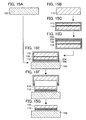
- FIGS. 14A to 14F are cross-sectional views illustrating an example of a method for manufacturing an SOI substrate and a semiconductor device
- FIGS. 15A to 15G are cross-sectional views illustrating an example of a method for manufacturing an SOI substrate used for a semiconductor device
- FIGS. 16A to 16H are cross-sectional views illustrating an example of a method for manufacturing an SOI substrate and a semiconductor device
- FIGS. 17A to 17H are cross-sectional views illustrating an example of a method for manufacturing a semiconductor device
- FIG. 18A is a plan view and FIG. 18B is a cross-sectional view illustrating an example a semiconductor device
- FIGS. 19A to 19D are cross-sectional views illustrating an example of a method for manufacturing a semiconductor device
- FIGS. 20A to 20D are cross-sectional views illustrating an example of a method for manufacturing a semiconductor device
- FIGS. 21A to 21C are cross-sectional views illustrating an example of a method for manufacturing an SOI substrate and a semiconductor device
- FIG. 22 is a graph showing luminance-current characteristics of a photoelectric conversion element
- FIG. 23A is a plan view and FIG. 23B is a cross-sectional view illustrating an example a semiconductor device
- FIGS. 24A to 24C are cross-sectional views illustrating an example of a method for manufacturing a semiconductor device
- FIG. 25A is a plan view and FIG. 25B is a cross-sectional view illustrating an example of a semiconductor device
- FIGS. 26A to 26D are cross-sectional views illustrating an example of a method for manufacturing a semiconductor device
- FIGS. 27A to 27D are cross-sectional views illustrating an example of a method for manufacturing a semiconductor device.
- FIGS. 28A to 28C are cross-sectional views illustrating an example of a method for manufacturing a semiconductor device.
- FIG. 1B corresponds to a cross section taken along line A-B of FIG. 1A .
- the photoelectric conversion element 180 includes an island-shaped single crystal semiconductor layer including a semiconductor region 164 having an effect of photoelectric conversion, a semiconductor region 158 having a first conductivity type (p-type conductivity, here), and a semiconductor region 162 having a second conductivity type (n-type conductivity, here); an insulating layer 154 and an insulating layer 166 which are formed so as to cover the island-shaped single crystal semiconductor layer; a first electrode 172 electrically connected to the semiconductor region 158 having the first conductivity type; and a second electrode 174 electrically connected to the semiconductor region 162 having the second conductivity type.
- the semiconductor region 158 having the first conductivity type and the semiconductor region 162 having the second conductivity type are adjacent to the semiconductor region 164 having an effect of photoelectric conversion and separated to each other by the semiconductor region 164 having an effect of photoelectric conversion.
- the first conductivity type and the second conductivity type can be interchangeable with each other.
- an insulating layer 112 is provided between the base substrate 100 and the photoelectric conversion element 180 .
- the insulating layer 112 has a function of fixing the photoelectric conversion element 180 to the base substrate 100 .
- the operation of the photoelectric conversion element 180 is as follows.
- the photoelectric conversion element 180 when light enter the semiconductor region 164 having an effect of photoelectric conversion, electrons and holes are generated in the semiconductor region.
- the electrons generated flow in a direction toward an n-type semiconductor region because of the influence of a self-aligned electric field.
- the holes generated flow in a direction toward a p-type semiconductor region.
- voltage is applied from the outside (for example, in the case where reverse bias is applied)
- electrons and holes flow because of the influence of a self-aligned electric field and the voltage from the outside.
- An optical sensor can be formed by utilizing the dependence of the resulting current upon the intensity of light.
- an electric generating system can be obtained by extracting electromotive force due to light to the outside of the photoelectric conversion element.
- the crystallinity of the island-shaped semiconductor layer included in the photoelectric conversion element is preferably a single crystal.
- the crystallinity of the semiconductor region 164 having an effect of photoelectric conversion is a single crystal.
- a semiconductor material of the single crystal for example, single crystal silicon can be used.
- the amount of dark current current when light irradiation is not performed
- the amount of current when light irradiation is performed can be increased as compared to the case of using a polycrystalline semiconductor. Accordingly, sensitivity as an optical sensor is improved.
- photoelectric conversion efficiency is improved.
- a structure in which light from an object (reflection light from the object, or the like) enters from the base substrate side can be employed.
- the degree of freedom of element layout is improved as compared to the case where light of the object enters from an electrode (or a wiring) side.
- the base substrate has a light-transmitting property, there is an advantage that integration can be performed easily as compared to the case where a base substrate which does not have a light-transmitting property.
- manufacturing steps of the photoelectric conversion element are described. First, manufacturing steps of an SOI substrate which can be used for manufacturing the photoelectric conversion element are described with reference to FIGS. 2A to 2F and FIGS. 3A to 3C . Then, manufacturing steps of the photoelectric conversion element in which the SOI substrate is used are described with reference to FIG. 4A to 4H .
- the light-transmitting base substrate 100 is prepared (see FIG. 2A ).
- a substrate formed of an insulator can be used as the light-transmitting base substrate 100 .
- a substrate formed of an insulator can be used.
- Specific examples thereof are as follows: a variety of glass substrates used in the electronics industry, such as substrates of aluminosilicate glass, aluminoborosilicate glass, and barium borosilicate glass; a quartz substrate; a ceramic substrate; and a sapphire substrate.
- the glass substrate contains a larger amount of barium oxide than boric acid, more-practical heat-resistant glass can be obtained. Therefore, in the case where a glass substrate needs to have heat resistance, it is preferable to use a glass substrate containing barium oxide and boric acid so that the amount of barium oxide is larger than that of boric acid.
- a description is given of the case where a glass substrate is used as the base substrate 100 . When a glass substrate which can have a larger size and is inexpensive is used as the base substrate 100 , cost reduction can be achieved.
- a surface of the base substrate 100 is preferably cleaned in advance. Specifically, ultrasonic cleaning is performed on the base substrate 100 by using a hydrochloric acid/hydrogen peroxide mixture (HPM), a sulfuric acid/hydrogen peroxide mixture (SPM), an ammonium hydroxide/hydrogen peroxide mixture (APM), diluted hydrogen fluoride (DHF), or the like.
- HPM hydrochloric acid/hydrogen peroxide mixture
- SPM sulfuric acid/hydrogen peroxide mixture
- APIAM ammonium hydroxide/hydrogen peroxide mixture
- DHF diluted hydrogen fluoride
- an insulating layer containing nitrogen for example, an insulating layer containing silicon nitride (SiN x ), silicon nitride oxide (SiN x O y ) (x>y), or the like
- an impurity element such as sodium (Na) contained in the base substrate into the semiconductor can be suppressed.
- an oxynitride refers to a substance that contains more oxygen (atoms) than nitrogen (atoms).
- a silicon oxynitride is a substance containing oxygen, nitrogen, silicon, and hydrogen in ranges of 50 at. % to 70 at. %, 0.5 at. % to 15 at. %, 25 at. % to 35 at. %, and 0.1 at. % to 10 at. %, respectively.
- the term nitride oxide means a substance in which the nitrogen content (atoms) exceeds the oxygen content (atoms).
- silicon nitride oxide is a substance containing oxygen, nitrogen, silicon, and hydrogen at concentrations ranging from 5 to 30 at.
- the above ranges are ranges in the case where measurement is performed using Rutherford backscattering spectrometry (RBS) or hydrogen forward scattering spectrometry (HFS). Moreover, the total for the content ratio of the constituent elements is maximum at 100 at. %.
- a single crystal semiconductor substrate 110 is prepared as a bonding substrate (see FIG. 2B ). Note that in this embodiment, after the base substrate 100 is processed, the single crystal semiconductor substrate 110 is processed as a bonding substrate; however, an embodiment of the disclosed invention is not construed as being limited thereto. Processing of the single crystal semiconductor substrate may be performed before processing of the base substrate. Alternatively, the base substrate and the bonding substrate may be processed concurrently.
- a single crystal semiconductor substrate formed with an element belonging to Group 14 of the periodic table such as a single crystal silicon substrate, a single crystal germanium substrate, or a single crystal silicon germanium substrate
- a single crystal semiconductor substrate of a compound such as a gallium arsenide substrate, an indium phosphide substrate, or the like
- Typical examples of commercially available silicon substrates are circular silicon substrates which are 5 inches (125 mm) in diameter, 6 inches (150 mm) in diameter, 8 inches (200 mm) in diameter, 12 inches (300 mm) in diameter, and 16 inches (400 mm) in diameter.
- the shape of the single crystal semiconductor substrate 110 is not limited to circular, and the single crystal semiconductor substrate 110 may be a substrate which has been processed into, for example, a rectangular shape or the like.
- the single crystal semiconductor substrate 110 can be manufactured using a CZ method or a floating zone (FZ) method.
- a single crystal silicon substrate for an integrated circuit as a bonding substrate is described; however, an embodiment of the invention disclosed is not construed as being limited to this structure.
- a solar-grade single crystal silicon substrate may be used.
- a polycrystalline semiconductor substrate including a polycrystalline silicon substrate can be used. Note that, in considering characteristics of the photoelectric conversion element to be formed, it is preferable that a single crystal semiconductor substrate be used.
- the insulating layer 112 is formed on a surface of the single crystal semiconductor substrate 110 (see FIG. 2C ).
- the surface of the single crystal substrate 110 be cleaned with a sulfuric acid/hydrogen peroxide mixture (SPM), an ammonium hydrogen peroxide mixture (APM), a hydrochloric acid/hydrogen peroxide mixture (HPM), diluted hydrofluoric acid (DHF), FPM (a mixed solution of hydrofluoric acid, hydrogen peroxide, and pure water), or the like before formation of the insulating layer 112 .
- SPM sulfuric acid/hydrogen peroxide mixture
- APIAM ammonium hydrogen peroxide mixture
- HPM hydrochloric acid/hydrogen peroxide mixture
- DHF diluted hydrofluoric acid
- FPM a mixed solution of hydrofluoric acid, hydrogen peroxide, and pure water
- the insulating layer 112 can be formed with a single layer of a silicon oxide film, a silicon oxynitride film, or the like, or a stacked layer of these films.
- a thermal oxidation method, a CVD method, a sputtering method, or the like can be employed to manufacture the insulating layer 112 .
- a silicon oxide film is preferably formed using organosilane such as tetraethoxysilane (abbreviation: TEOS, chemical formula: Si(OC 2 H 5 ) 4 ).
- the insulating layer 112 (here, a silicon oxide film) is formed.
- the thermal oxidation treatment is preferably performed in an oxidation atmosphere to which a halogen is added.
- the single crystal semiconductor substrate 110 is subjected to the thermal oxidation treatment in an oxidation atmosphere to which chlorine (Cl) is added, whereby the insulating layer 112 is formed through chlorine oxidation.
- the insulating layer 112 is an insulating layer containing chlorine atoms.
- the chlorine atoms contained in the insulating layer 112 form distortion in the insulating layer 112 .
- the water absorptance of the insulating layer 112 is increased, and the water diffusion rate is increased.
- the water existing at the surface can be quickly absorbed into the insulating layer 112 and diffused thereto. Accordingly, defective bonding caused by water can be suppressed.
- heavy metal such as Fe, Cr, Ni, or Mo
- impurities from the base substrate 100 such as sodium (Na) can be fixed, so that contamination of the single crystal semiconductor substrate 110 can be prevented.
- the halogen atoms contained in the insulating layer 112 are not limited to chlorine atoms. Fluorine atoms may be contained in the insulating layer 112 .
- a method by which the surface of the single crystal semiconductor substrate 110 is oxidized with fluorine can be used.
- fluorine oxidation a method in which the single crystal semiconductor substrate 110 is soaked in an HF solution and then thermal oxidation treatment is performed in an oxidizing atmosphere, a method in which NF 3 is added to an oxidizing atmosphere to perform thermal oxidation treatment, and the like are given.
- ions accelerated by an electrical field are added to the single crystal semiconductor substrate 110 , whereby an embrittled region 114 in which a crystal structure is damaged is formed at a predetermined depth in the single crystal semiconductor substrate 110 (see FIG. 2D ).
- the surface of the single crystal semiconductor substrate 110 and the surface of the insulating layer 112 are preferably cleaned before the treatment for addition of ions.
- the depth at which the embrittled region 114 is formed can be adjusted by the kinetic energy, mass, charge, or incidence angle of the ions, or the like.
- the embrittled region 114 is formed at approximately the same depth as the average penetration depth of the ions. Therefore, the thickness of a single crystal semiconductor layer to be separated from the single crystal semiconductor substrate 110 can be adjusted with the depth at which the ions are added.
- the average penetration depth may be adjusted so that the thickness of the single crystal semiconductor layer is approximately 10 nm to 1 ⁇ m. Note that characteristics of a photoelectrical conversion device tend to be drastically improved when the thickness of the single crystal semiconductor layer is larger than or equal to a predetermined thickness. Therefore, for example, it is preferable that the single crystal semiconductor layer be formed to a thickness of 100 nm or more.
- the above ion irradiation treatment can be performed with an ion-doping apparatus or an ion-implantation apparatus.
- the ion-doping apparatus there is a non-mass-separation-type apparatus in which plasma excitation of a process gas is performed and an object to be processed is irradiated with all kinds of ion species generated.
- the object to be processed is irradiated with ion species of plasma without mass separation.
- an ion-implantation apparatus is a mass-separation apparatus. In the ion-implantation apparatus, mass separation of ion species of plasma is performed and the object to be processed is irradiated with ion species having predetermined masses.
- an ion-doping apparatus is used to add hydrogen to the single crystal semiconductor substrate 110 .
- a gas containing hydrogen is used as a source gas.
- the proportion of H 3 + is preferably set high. Specifically, it is preferable that the proportion of H 3 + be set 50% or higher (more preferably, 80% or higher) with respect to the total amount of H + , H 2 + , and H 3 + . With a high proportion of H 3 + , the efficiency of ion irradiation can be improved.
- ions to be added are not limited to ions of hydrogen. Ions of helium or the like may be added. Further, the ions to be added are not limited to one kind of ions, and plural kinds of ions may be added. For example, in the case of performing irradiation with hydrogen and helium concurrently using an ion-doping apparatus, the number of steps can be reduced as compared to the case of performing irradiation of hydrogen and helium in separate steps, and increase in surface roughness of a single crystal semiconductor layer to be formed later can be suppressed.
- heavy metal may also be added when the embrittled region 114 is formed using the ion-doping apparatus; however, the ion irradiation is performed through the insulating layer 112 containing halogen atoms, whereby contamination of the single crystal semiconductor substrate 110 due to the heavy metal can be prevented.
- the surface of the base substrate 100 and the surface of the single crystal semiconductor substrate 110 are disposed to face each other and the surface of the base substrate 100 and the surface of the insulating layer 112 are disposed in close contact with each other.
- the base substrate 100 and the single crystal semiconductor substrate 110 can be bonded together (see FIG. 2E ).
- a pressure of 0.001 N/cm 2 to 100 N/cm 2 inclusive be applied to part of the base substrate 100 or part of the single crystal semiconductor substrate 110 .
- a pressure of 1 N/cm 2 to 20 N/cm 2 inclusive be applied thereto.
- a bonding between the base substrate 100 and the insulating layer 112 is generated at the portion to which the pressure is applied and spontaneous bonding proceeds throughout the entire surface from the portion. This bonding is performed under the action of the Van der Waals force or hydrogen bonding and can be performed at room temperature.
- surfaces to be bonded together are preferably subjected to surface treatment.
- surface treatment bonding strength at an interface between the surfaces to be bonded together can be improved.
- wet treatment As the surface treatment, wet treatment, dry treatment, or a combination of wet treatment and dry treatment can be used. Alternatively, wet treatment may be used in combination with different wet treatment or dry treatment may be used in combination with different dry treatment.
- ozone treatment using ozone water ozone water cleaning
- megasonic cleaning two-fluid cleaning (method in which functional water such as pure water or hydrogenated water and a carrier gas such as nitrogen are sprayed together), and the like
- dry treatment ultraviolet treatment, ozone treatment, plasma treatment, plasma treatment with bias application, radical treatment, and the like can be given.
- the above-described surface treatment on an object a single crystal semiconductor substrate, an insulating layer formed on a single crystal semiconductor substrate, a support substrate, or an insulating layer formed on a support substrate
- the wet treatment is effective for the removal of macro dust and the like adhering to a surface of the object to be processed.
- the dry treatment is effective for the removal or decomposition of micro dust such as an organic substance which adheres to a surface of the object to be processed.
- the case in which the dry treatment such as ultraviolet treatment is performed and then the wet treatment such as cleaning is performed is preferable because the surface of the object can be made clean and hydrophilic and generation of watermarks in the surface of the object can be suppressed.
- Ozone or oxygen in an active state such as singlet oxygen enables organic substances bonded on the surface of the object to be removed or decomposed effectively.
- the treatment using ozone or oxygen in an active state such as singlet oxygen may be combined with treatment using ultraviolet light having wavelengths less than 200 nm, so that the organic substances bonded on the surface of the object can be removed more effectively. Specific description thereof will be made below.
- irradiation with ultraviolet light under the atmosphere containing oxygen is performed to perform the surface treatment of the object.
- Irradiation with ultraviolet light having wavelengths less than 200 nm and ultraviolet light having wavelengths greater than or equal to 200 nm under the atmosphere containing oxygen may be performed, so that ozone and singlet oxygen can be generated.
- irradiation with ultraviolet light having wavelengths less than 180 nm may be performed, so that ozone and singlet oxygen can be generated.
- reaction formula (1) irradiation with light (h ⁇ 1 ) including a wavelength ( ⁇ 1 nm) of less than 200 nm in an atmosphere containing oxygen (O 2 ) is performed to generate oxygen atoms (O( 3 P)) in a ground state.
- reaction formula (2) an oxygen atom (O( 3 P)) in a ground state and oxygen (O 2 ) are reacted with each other to generate ozone (O 3 ).
- irradiation with light (h ⁇ 2 ) having wavelengths ( ⁇ 2 nm) greater than or equal to 200 nm in the atmosphere containing generated ozone (O 3 ) is performed to generate singlet oxygen in an excited state (O( 1 D)).
- irradiation with light including a wavelength of less than 200 nm among ultraviolet is performed to generate ozone while irradiation with light including a wavelength of greater than or equal to 200 nm among ultraviolet is performed to generate singlet oxygen by decomposing ozone.
- reaction formula (4) irradiation with ultraviolet light (h ⁇ 3 ) having a wavelength ( ⁇ 3 nm) of less than 180 nm in an atmosphere containing oxygen (O 2 ) is performed to generate singlet oxygen O( 1 D) in an excited state and an oxygen atom (O( 3 P)) in a ground state.
- an oxygen atom (O( 3 P)) in a ground state and oxygen (O 2 ) are reacted with each other to generate ozone (O 3 ).
- irradiation with light including a wavelength ( ⁇ 3 nm) of less than 180 nm in an atmosphere containing generated ozone (O 3 ) is performed to generate singlet oxygen in an excited state and oxygen.
- irradiation with light including a wavelength of less than 180 nm among ultraviolet is performed to generate ozone and to generate singlet oxygen by decomposing ozone or oxygen.
- the above-described surface treatment can be performed by, for example, irradiation with a Xe excimer UV lamp under the atmosphere containing oxygen.
- Chemical bond of an organic substance bonded on the surface of an object is cut by the ultraviolet light having wavelengths less than 200 nm, and an organic substance or an organic substance in which the chemical bond is cut which is bonded on the surface of the object can be oxidative-decomposed by ozone or singlet oxygen to be removed.
- the surface treatment as described above can enhance the hydrophilicity and cleanliness of the surface of the object to be processed, making the bond more preferable.
- heat treatment for improving the bonding strength may be performed after the bonding is performed.
- This heat treatment is performed at a temperature at which separation at the embrittled region 114 does not occur (for example, a temperature of a room temperature or more and less than 400° C.).
- the base substrate 100 and the insulating layer 112 may be bonded together while being heated at a temperature in this temperature range.
- the heat treatment can be performed using a diffusion furnace, a heating furnace such as a resistance heating furnace, a rapid thermal annealing (RTA) apparatus, a microwave heating apparatus, or the like.
- RTA rapid thermal annealing
- microwave heating apparatus or the like.
- heat treatment is performed at a temperature of, for example, 400° C. or higher and equal to or lower than the upper temperature limit of the base substrate 100 to cause separation of the single crystal semiconductor substrate 110 at the embrittled region 114 , whereby a single crystal semiconductor layer 116 is aimed over the base substrate 100 with the insulating layer 112 therebetween (see FIG. 2F and FIG. 3A ).
- the element added is separated out, as a molecule, in microvoids which are formed in the embrittled region 114 , and the internal pressure of the microvoids is increased.
- the increased pressure causes a crack in the embrittled region 114 , so that the single crystal semiconductor substrate 110 is separated along the embrittled region 114 .
- the insulating layer 112 is bonded to the base substrate 100 , the single crystal semiconductor layer 116 which is separated from the single crystal semiconductor substrate 110 remains over the base substrate 100 .
- a surface of the single crystal semiconductor layer 116 is irradiated with laser light 130 , whereby a single crystal semiconductor layer 118 in which a surface of flatness is improved and the number of defects is reduced is formed (see FIGS. 3B and 3C ).
- the single crystal semiconductor layer 116 be partially melted by the irradiation with the laser light 130 . This is because, if the single crystal semiconductor layer 116 is completely melted, it is microcrystallized due to disordered nucleation after being in a liquid phase, so that the crystallinity thereof decreases. On the other hand, by partial melting, crystal growth proceeds based on a non-melted solid phase portion. Therefore, crystal quality can be improved as compared to the case where the single crystal semiconductor layer 116 is completely melted. In addition, incorporation of oxygen, nitrogen, or the like from the insulating layer 112 can be suppressed.
- partial melting in the above description means melting of the single crystal semiconductor layer 116 with laser light irradiation from a top surface of the single crystal semiconductor layer 116 to an upper side of an interface of the insulating layer 112 (that is, smaller than the thickness of the single crystal semiconductor layer 116 ). In other words, it refers to a state in which the upper portion of the single crystal semiconductor layer 116 is melted to be in a liquid phase whereas the lower portion is not melted and remains in a solid phase. Further, the term “complete melting” means that the single crystal semiconductor layer 116 is melted to an interface between the single crystal semiconductor layer 116 and the insulating layer 112 and is in a liquid state.
- a pulsed laser is preferably used. This is because high-energy pulsed laser light can easily produce a partially melted state.
- the oscillation frequency is preferably, but not limited to, from 1 Hz to 10 MHz inclusive.
- the pulsed laser examples include an Ar laser, a Kr, laser, an excimer laser (ArF, KrF, XeCl) laser, a CO 2 laser, a YAG laser, a YVO 4 laser, a YLF laser, a YAlO 3 laser, a GdVO 4 laser, a Y 2 O 3 laser, a ruby laser, an alexandrite laser, a Ti:sapphire laser, a copper vapor laser, a gold vapor laser, and the like.
- a continuous-wave laser may be used if it can cause partial melting.
- Example of the continuous-wave laser include an Ar laser, a Kr laser, a CO 2 laser, a YAG laser, a YVO 4 laser, a YLF laser, a YAlO 3 laser, a GdVO 4 laser, a Y 2 O 3 laser, a ruby laser, an alexandrite laser, a Ti:sapphire laser, a helium-cadmium laser, and the like.
- the wavelength of the laser light 130 needs to be selected so that the laser light 130 is absorbed by the single crystal semiconductor layer 116 .
- the wavelength may be determined in consideration of the skin depth of the laser light and the like.
- the wavelength can be set in the range of 250 nm to 700 nm inclusive.
- the energy density of the laser light 130 can be determined in consideration of the wavelength of the laser light 130 , the skin depth of the laser light 130 , the thickness of the single crystal semiconductor layer 116 , or the like.
- the energy density of the laser light 130 may be set, for example, in the range of 300 mJ/cm 2 to 800 mJ/cm 2 inclusive. Note that the above range of the energy density is an example when a XeCl excimer laser (wavelength: 308 nm) is used as the pulsed laser.
- the irradiation with the laser light 130 can be performed in an atmosphere containing oxygen such as an air atmosphere or in an inert atmosphere such as a nitrogen atmosphere or an argon atmosphere.
- an atmosphere containing oxygen such as an air atmosphere or in an inert atmosphere such as a nitrogen atmosphere or an argon atmosphere.
- the irradiation with the laser beam 130 may be performed in an airtight chamber while the atmosphere in the chamber may be controlled.
- an inert atmosphere can be obtained by blowing an inert gas such as a nitrogen gas to the surface which is irradiated with the laser light 130 .
- the irradiation in an inert atmosphere such as a nitrogen atmosphere is more effective in improving flatness of the single crystal semiconductor layer 116 than the irradiation in an air atmosphere.
- the inert atmosphere has higher effect of suppressing generation of cracks and ridges than the air atmosphere, and the energy density range applicable for the laser light 130 is widened.
- the irradiation with the laser light 130 may be performed in a reduced-pressure atmosphere. When irradiation with the laser light 130 is performed in a reduced-pressure atmosphere, the same effects as those obtained by the irradiation in an inert atmosphere can be obtained.
- the irradiation treatment with the laser beam 130 is performed after the heat treatment for separation of the single crystal semiconductor layer 116 in this embodiment, an embodiment of the disclosed invention is not construed as being limited to this.
- etching treatment may be performed to remove a region including many defects at the surface of the single crystal semiconductor layer 116 .
- the irradiation treatment with the laser light 130 may be performed.
- the irradiation treatment with the laser light 130 may be performed.
- the etching treatment may be either wet etching or dry etching.
- the surface of the single crystal semiconductor layer 116 be cleaned before the irradiation treatment with the laser light 130 .
- a step of thinning the single crystal semiconductor layer 116 may be performed.
- one or a combination of dry etching and wet etching may be employed.
- the SOI substrate having the structure in which the insulating layer 112 and the single crystal semiconductor layer 118 are provided over the base substrate 100 is prepared according to the above steps (see FIG. 4A ).
- a small quantity of a p-type impurity element such as boron, aluminum, or gallium, or a small quantity of an n-type impurity element such as phosphorus or arsenic may be added to the single crystal semiconductor layer 118 .
- a region to which the impurity element is added and the kind of the impurity element to be added can be changed as appropriate.
- a mask 150 is formed over the single crystal semiconductor layer 118 .
- the single crystal semiconductor layer 118 is patterned using the mask 150 , so that an island-shaped semiconductor layer 152 used for the photoelectric conversion element is formed (see FIG. 4B ).
- the mask 150 can be formed by photolithography or the like using a resist material. Further, as etching treatment in the patterning, either wet etching or dry etching can be employed.
- the insulating layer 154 is formed so as to cover the semiconductor layer 152 (see FIG. 4C ).
- the insulating layer 154 is not necessarily formed, but when the insulating layer 154 is provided, it can suppress damage to the semiconductor layer 152 at the time of addition of an impurity element performed later.
- a single-layer silicon oxide film is formed by a plasma CVD method.
- a film containing silicon oxynitride, silicon nitride oxide, silicon nitride, hafnium oxide, aluminum oxide, tantalum oxide, or the like can be formed to have a single-layer structure or a stacked-layer structure.
- a sputtering method or a method using oxidation or nitridation by high density plasma treatment can be given.
- a high-density plasma treatment is performed, for example, using a mixed gas of a rare gas such as helium, argon, krypton, or xenon; an oxygen gas; a nitrogen oxide gas; an ammonia gas; a nitrogen gas; a hydrogen gas; or the like.
- a rare gas such as helium, argon, krypton, or xenon
- an oxygen gas a nitrogen oxide gas
- an ammonia gas a nitrogen gas
- a hydrogen gas or the like.
- the insulating layer 154 When a surface of the semiconductor layer 152 is oxidized or nitrided by oxygen radicals (OH radicals may be included) or nitrogen radicals (NH radicals may be included) which are produced by such high-density plasma, the insulating layer 154 with a thickness of 1 nm to 20 nm inclusive, preferably 2 nm to 10 nm inclusive can be formed.
- oxygen radicals OH radicals may be included
- NH radicals nitrogen radicals
- oxidation or nitridation of the semiconductor layer by the high-density plasma treatment is a solid-phase reaction
- an interface state density between the insulating layer 154 and the semiconductor layer 152 can be decreased sufficiently.
- the semiconductor layer is a single crystal
- the insulating layer 154 with high uniformity and sufficiently-low interface state density can be formed.
- the insulating layer 154 may be formed by thermally oxidizing the semiconductor layer 152 . In the case of such thermal oxidation, it is necessary to use the base substrate 100 having a certain degree of heat resistance.
- hydrogen contained in the insulating layer 154 may be diffused into the semiconductor layer 152 by performing heat treatment at a temperature of 350° C. to 450° C. inclusive after formation of the insulating layer 154 containing hydrogen.
- the insulating layer 154 can be formed using silicon nitride or silicon nitride oxide by a plasma CVD method.
- a process temperature is preferably set to 350° C. or lower. In this manner, by supplying the semiconductor layer 152 with hydrogen, defects in the semiconductor layer 152 and defects at the interface between the insulating layer 154 and the semiconductor layer 152 can be reduced effectively.
- a mask 156 is selectively formed over the insulating layer 154 , and an impurity element imparting the first conductivity type is added to part of the semiconductor layer 152 .
- the semiconductor region 158 having the first conductivity type is formed (see FIG. 4D ).
- boron is used for the impurity element imparting the first conductivity type and the first conductivity type is p-type conductivity: however, an embodiment of the disclosed invention is not limited thereto.
- Aluminum or the like may be used as the impurity element imparting the first conductivity type.
- the first conductivity type is n-type conductivity, phosphorus, arsenic, or the like can be used.
- the mask 156 may be formed in a manner similar to that of the mask 150 .
- boron may be added using B 2 H 6 as a source gas at an accelerating voltage of 10 kV to 40 kV with a dosage of approximately 3.0 ⁇ 10 14 cm ⁇ 2 to 1.0 ⁇ 10 17 cm ⁇ 2 .
- the conditions of the addition of the impurity element can be changed as appropriate depending on required characteristics. Dark current tends to be reduced when the dosage is reduced. This is because damage to the semiconductor layer 152 is small when an impurity element is added under a low-dosage condition, so that current due to defects is not generated while damage of the semiconductor layer 152 is large when an impurity element is added with a high-dosage condition, so that a carrier trap due to defects is generated. Note that the mask 156 is removed after formation of the semiconductor region 158 having the first conductivity type.
- a mask 160 is selectively formed over the insulating layer 154 and an impurity element imparting the second conductivity type is added to part of the semiconductor layer 152 . Accordingly, the semiconductor region 162 having the second conductivity type is formed, and the semiconductor region 164 having an effect of photoelectric conversion, to which the impurity element imparting the first conductivity type and the impurity element imparting the second conductivity type are not added (see FIG. 4E ) is formed.
- the second conductivity type is different from the first conductivity type. That is, when the first conductivity type is p-type, the second conductivity is n-type; whereas the first conductivity type is n-type, the second conductivity type is p-type.
- phosphorus is used as the impurity element imparting the second conductivity type and the second conductivity type is n-type.
- arsenic or the like can be used as the impurity element imparting n-type conductivity.
- the mask 160 is formed in a manner similar to that of the mask 150 or the mask 156 .
- phosphorus may be added using PH 3 as a source gas at an accelerating voltage of 10 kV to 40 kV with a dosage of approximately 1.0 ⁇ 10 14 cm ⁇ 2 to 5.0 ⁇ 10 16 cm ⁇ 2 .
- the conditions of the addition of the impurity element can be changed as appropriate depending on required characteristics. In a manner similar to the case of addition of the impurity element imparting the first conductivity type, dark current can be suppressed when the dosage is reduced.
- the mask 160 is removed after formation of the semiconductor region 162 having the second conductivity type.
- the width of the semiconductor region 164 having an effect of photoelectric conversion is 0.1 ⁇ m to 20 ⁇ m, preferably 3 ⁇ m to 10 ⁇ m. Needless to say, if processing accuracy of the mask 156 and the mask 160 permits, the width of the semiconductor region 164 can be 0.1 ⁇ m or smaller.
- FIG. 5 a vertical axis represents current (A).
- a circle represents current (photocurrent) at the time of light irradiation of 1000 cd/m 2
- an X mark represents current (dark current) when light irradiation is not performed.
- the dosage of the impurity element imparting the first conductivity type (boron here) is 3.0 ⁇ 10 15 cm ⁇ 2
- the dosage of the impurity element imparting the second conductivity type is 1.0 ⁇ 10 15 cm ⁇ 2 .
- the dosage of the impurity element imparting the first conductivity type is 1.0 ⁇ 10 16 cm ⁇ 2
- the dosage of the impurity element imparting the second conductivity type is 5.0 ⁇ 10 15 cm ⁇ 2 .
- the accelerating voltage is 20 kV.
- the other parameters are the same in both of the Conditions A and B.
- the insulating layer 166 is formed so as to cover the semiconductor layer 152 and the insulating layer 154 (see FIG. 4F ).
- the insulating layer 166 is not necessarily provided, when the insulating layer 166 is formed, an impurity such as an alkali metal or an alkaline earth metal can be prevented from entering the semiconductor layer 152 .
- a surface of the photoelectric conversion element to be formed can be planarized.
- the insulating layer 166 can be formed using, for example, a material such as silicon oxide, silicon nitride, silicon oxynitride, silicon nitride oxide, aluminum nitride, or aluminum oxide.
- the insulating layer 166 is formed with a stacked-layer structure of a silicon oxynitride film with a thickness of approximately 300 nm and a silicon oxide film with a thickness of approximately 600 nm, which are formed by a CVD method.
- an embodiment of the disclosed invention is not limited thereto.
- a single-layer structure or a stacked-layer structure with three layers or more can be employed.
- the insulating layer 166 can be formed using an organic material having heat resistance, such as polyimide, acrylic, benzocyclobutene, polyamide, or epoxy.
- organic materials such as polyimide, acrylic, benzocyclobutene, polyamide, or epoxy.
- a low-dielectric constant material a low-k material
- siloxane-based resin PSG (phosphosilicate glass), BPSG (borophosphosilicate glass), or the like.
- a siloxane-based resin corresponds to a resin containing a Si—O—Si bond which is formed using a siloxane-based material as a starting material.
- the following method can be employed depending on the material: a method such as a CVD method, a sputtering method, an SOG method, spin coating, dip coating, spray coating, or a droplet discharging method (e.g., ink jetting, screen printing, or offset printing), or with a tool (equipment) such as a doctor knife, a roll coater, a curtain coater, or a knife coater.
- a method such as a CVD method, a sputtering method, an SOG method, spin coating, dip coating, spray coating, or a droplet discharging method (e.g., ink jetting, screen printing, or offset printing), or with a tool (equipment) such as a doctor knife, a roll coater, a curtain coater, or a knife coater.
- a contact hole 168 and a contact hole 170 are formed in the insulating layer 154 and the insulating layer 166 so that the semiconductor layer 152 is partly exposed (see FIG. 4G ).
- the contact hole 168 and the contact hole 170 are formed so that the semiconductor region 158 having the first conductivity type and the semiconductor region 162 having the second conductivity type are partly exposed.
- the contact hole 168 and the contact hole 170 can be formed by etching treatment or the like after selective formation of the mask.
- the etching treatment dry etching using a mixed gas of CHF 3 and He as an etching gas can be employed; however, an embodiment of the disclosed invention is not limited thereto.
- a conductive layer which is in contact with the semiconductor layer 152 through the contact holes is formed and then patterned so that the first electrode 172 and the second electrode 174 are formed (see FIG. 4H ).
- the conductive layer, from which the first electrode 172 and the second electrode 174 are formed, can be formed by a CVD method, a sputtering method, an evaporation method, or the like.
- the conductive layer aluminum (Al), tungsten (W), titanium (Ti), tantalum (Ta), molybdenum (Mo), nickel (Ni), platinum (Pt), copper (Cu), gold (Au), silver (Ag), manganese (Mn), neodymium (Nd), carbon (C), silicon (Si), or the like can be used.
- an alloy containing the above-described material as its main component or a compound containing the above-described material may be used.
- the conductive layer may have a single-layer structure or a stacked-layer structure.
- the conductive layer is formed with a stacked-layer structure so that each of the first electrode 172 and the second electrode 174 has a stacked-layer structure, a stacked-layer structure of a barrier film, an aluminum silicon film, and a barrier film; a stacked-layer structure of a barrier film, an aluminum silicon film, a titanium nitride film, and a barrier film; or the like may be used, for example.
- the barrier film refers to a film formed using titanium, a nitride of titanium, molybdenum, a nitride of molybdenum, or the like.
- the photoelectric conversion element 180 is formed over the light-transmitting base substrate 100 .
- the vertical axis represents current (A) and the horizontal axis represents luminance (cd/m 2 ) of light with which the element is irradiated.
- a photoelectric conversion element formed by the method described in this embodiment (in particular, the photoelectric conversion element in which a glass substrate is used as a base substrate: c-Si on glass) and a photoelectric conversion element formed using a polycrystalline silicon over a glass substrate (p-Si on glass).
- the thicknesses of semiconductor layers in the photoelectric conversion elements slightly differ from each other, which are 60 nm (c-Si on glass) and 50 nm (p-Si on glass), and the other conditions are the same. Further, measurement is performed while a reverse bias voltage of 0.5 V is applied.
- a photoelectric conversion element 180 relating to an embodiment of the disclosed invention is formed over a light-blocking layer 204 provided over a light-transmitting substrate 100 (see FIGS. 7A and 7B ).
- FIG. 7B corresponds to a cross section along line A-B of FIG. 7A .
- the photoelectric conversion element 180 is a lateral junction pin diode and includes an island-shaped single crystal semiconductor layer including a semiconductor region 164 having an effect of photoelectric conversion, a semiconductor region 158 having a first conductivity type, and a semiconductor region 162 having a second conductivity type; a first electrode 172 electrically connected to the semiconductor region 158 having the first conductivity type; and a second electrode 174 electrically connected to the semiconductor region 162 having the second conductivity type.
- the first electrode 172 and the second electrode 174 are electrically connected to the semiconductor region 158 having the first conductivity type and the semiconductor region 162 having the second conductivity type respectively, through contact holes.
- the light-blocking layer 204 By providing the light-blocking layer 204 so as to overlap with the photoelectric conversion element 180 , light from a light source provided for the light-transmitting substrate 100 can be prevented from directly striking the photoelectric conversion element 180 , which functions as a photo sensor.
- the light-blocking layer 204 is formed having a width larger than that of the island-shaped single crystal semiconductor layer included in the photoelectric conversion element 180 , light can be prevented from directly striking the photoelectric conversion element 180 more surely.
- FIG. 8 illustrates a relation between the photoelectric conversion element 180 and a direction of incident light.
- a color filter 502 is provided over the insulating layer 166 and the insulating layer 500 .
- a light source 504 is provided on the light-transmitting substrate 100 side and an object 506 is arranged in a counter substrate (not illustrated) side
- the object 506 on the counter substrate side is irradiated with light 508 from the light source 504 .
- the photoelectric conversion element photo sensor
- the structure in which the light-blocking layer 204 is provided on the light-transmitting substrate 100 side is more effective when further miniaturized pixels with small pitches are needed in order to improve resolution of image capture in a display device in which contact area sensors that capture images are arranged in the whole display screen of a touch panel.
- first electrode 172 and second electrode 174 are electrically connected to the semiconductor region 158 having the first conductivity type and the semiconductor region 162 having the second conductivity type, respectively, through the contact holes formed in the insulating layer 154 and the insulating layer 166 . That is, the first electrode 172 and second electrode 174 are provided on a side opposite to the light-blocking layer 204 with the semiconductor region 164 having an effect of photoelectric conversion interposed therebetween, so as to be light blocking walls. Accordingly, light from an oblique direction which is transmitted through an adjacent color filter with a different color can be prevented, so that color separation can be favorably performed and color mixing can be further suppressed.
- the light-transmitting base substrate 100 and the single crystal semiconductor substrate 110 serving as a bonding substrate are prepared (see FIGS. 9A and 9 B).
- the details of the base substrate 100 and the single crystal semiconductor substrate 110 , for which the above embodiment can be referred to, are omitted here.
- an insulating layer 202 , the light-blocking layer 204 , and the insulating layer 206 are stacked in this order over a surface of the base substrate 100 (see FIG. 9C ).
- the insulating layer 202 can be formed with a single layer or a stacked layer using, for example, a silicon oxide film, a silicon nitride film, a silicon nitride oxide film, a silicon oxynitride film, an aluminum nitride film, an aluminum oxide film, and/or the like.
- a silicon oxide film, a silicon nitride film, a silicon nitride oxide film, a silicon oxynitride film, an aluminum nitride film, an aluminum oxide film, and/or the like When an insulating layer containing nitrogen is formed as the insulating layer 202 , diffusion of an impurity element such as sodium (Na) contained in the base substrate into the semiconductor can be suppressed.
- a thermal oxidation method, a CVD method, a sputtering method, or the like can be employed to manufacture the insulating layer 202 .
- the light-blocking layer 204 is preferably formed using a film formed of a metal having heat resistance, such as tungsten, molybdenum, tantalum, titanium, niobium, nickel, cobalt, zirconium, or zinc.
- a metal having heat resistance such as tungsten, molybdenum, tantalum, titanium, niobium, nickel, cobalt, zirconium, or zinc.
- molybdenum or tungsten is preferably used.
- an organic resin containing black colorant such as carbon black or titanium lower oxide can be used.
- a film using chromium can be used as the light-blocking layer 204 .
- a material which has oxidation resistance in addition to heat resistance be used as the light-blocking layer 204 .
- the light-blocking layer 204 can be formed using a sputtering method, an evaporation method, or the like.
- the embrittled region 114 is formed at a predetermined depth from the surface of the single crystal semiconductor substrate 110 , and the base substrate 100 and the single crystal semiconductor substrate 110 are bonded together with the insulating layer 202 , the light-blocking layer 204 , the insulating layer 206 , and the insulating layer 112 therebetween (see FIGS. 9D and 9E ).
- the insulating layer 112 can be formed with a single layer or a stacked layer of a silicon oxide film, a silicon oxynitride film, and/or the like, for example.
- the aforementioned embodiment can be referred to for a detailed description thereof.
- the insulating layer 112 is formed over the single crystal semiconductor substrate 110 here, the insulating layer 112 may be formed by a thermal oxidation method so as to cover the single crystal semiconductor substrate.
- the embrittled region 114 can be formed by adding ions of hydrogen or the like having kinetic energy to the single crystal semiconductor substrate 110 .
- the aforementioned embodiment can be referred to for a detailed description thereof.
- Bonding is performed as follows: the base substrate 100 and the single crystal semiconductor substrate 110 are disposed in close contact with each other with the insulating layer 202 , the light-blocking layer 204 , the insulating layer 206 , and the insulating layer 112 therebetween, and then a pressure of from 1 N/cm 2 to 500 N/cm 2 inclusive is applied to a portion of the base substrate 100 or the single crystal semiconductor substrate 110 . Then, the insulating layer 206 and the insulating layer 112 start to be bonded together from the pressure-applied portion, and the bonding spontaneously spreads to the entire area. This bonding is performed under the action of the Van der Waals force or hydrogen bonding and can be performed at room temperature.
- heat treatment for improving the bonding strength may be performed after the bonding is performed. This heat treatment is performed at a temperature at which separation at the embrittled region 114 does not occur (for example, higher than or equal to room temperature and lower than 400° C.).
- the insulating layer 206 over the base substrate 100 and the insulating layer 112 may be bonded together while being heated at a temperature in this temperature range.
- the heat treatment can be performed using a diffusion furnace, a heating furnace such as a resistance heating furnace, a rapid thermal annealing (RTA) apparatus, a microwave heating apparatus, or the like.
- the surface of the single crystal semiconductor layer 116 is irradiated with the laser light 130 , whereby a single crystal semiconductor layer 118 in which the flatness of the surface is improved and the number of defects is reduced is formed (see FIGS. 10A and 10B ).
- the above embodiment can be referred to for details of the irradiation with the laser light 130 .
- a mask 150 is formed over the single crystal semiconductor layer 118 , and the single crystal semiconductor layer 118 is patterned (processed) using the mask 150 , so that island-shaped semiconductor layers 152 for the photoelectric conversion element are formed (see FIGS. 10C and 10D ).
- the mask 150 can be formed by photolithography with the use of a resist material or the like.
- the etching treatment in the patterning either wet etching or dry etching can be employed.
- the single crystal semiconductor layer 118 is patterned to form the island-shaped semiconductor layers 152 by dry etching using a mixed gas of BCl 3 , CF 4 , and O 2 as a reactive gas.
- the drawings are schematic views. Therefore, needless to say, a scale such as the size of the island-shaped semiconductor layers 152 with respect to the whole single crystal semiconductor layer 118 in the drawings is different from an actual scale in some cases.
- the mask 150 is removed and then a mask 250 is formed so as to cover each of the island-shaped semiconductor layers 152 (see FIG. 10E ).
- the mask 250 can be formed by photolithography with the use of a resist material or the like.
- the insulating layer 112 and the insulating layer 206 are etched using the mask 250 (see FIG. 10F ).
- the etching treatment either wet etching or dry etching can be employed.
- dry etching using a mixed gas of CHF 3 and He as a reactive gas this embodiment is not limited thereto.
- the light-blocking layer 204 is patterned using the mask 250 so that island-shaped light-blocking layers 208 are formed (see FIG. 10G ).
- the etching treatment in the patterning either wet etching or dry etching can be employed.
- the light-blocking layer 204 is patterned by dry etching using a mixed gas of Cl 2 , CF 4 , and O 2 as a reactive gas to form the island-shaped light-blocking layers 208 .
- the mask 250 is removed (see FIG. 10H ).
- the island-shaped semiconductor layers 152 which overlap with the island-shaped light-blocking layers 208 and each have a smaller width than the respective island-shaped light-blocking layers 208 can be obtained.
- the photoelectric conversion element is formed using the island-shaped semiconductor layer 152 .
- the island-shaped light-blocking layer 208 is selectively formed over a region overlapping with the island-shaped semiconductor layer 152 , direct irradiation of the photoelectric conversion element 180 with light which is transmitted through the light-transmitting substrate can be prevented.
- a transistor can be formed with the use of the island-shaped semiconductor layer 152 at the same time as formation of the photoelectric conversion element, using some manufacturing steps in common with those of the photoelectric conversion element. Also in this case, by providing the light-blocking layer so as to overlap with an active layer of a transistor, generation of channel leakage current due to light can be suppressed.
- the steps by which the island-shaped semiconductor layer 152 having a smaller width than the island-shaped light-blocking layer 208 is obtained are described here.
- the light-blocking layer 204 may be patterned using the mask 150 so that the island-shaped light-blocking layer 208 having almost the same shape as the island-shaped semiconductor layer 152 may be formed as long as a sufficient light blocking effect can be obtained.
- FIGS. 10A to 10H a manufacturing method in which arrangement of the light-blocking layer is different from that of FIGS. 10A to 10H will be described with reference to drawings.
- a manufacturing method of a semiconductor device in which only part of the light-blocking layer in a region serving as a display portion of a touch panel is removed so that an opening portion is formed will be described with reference to FIGS. 11A to 11H .
- FIG. 11A corresponds to FIG. 10B .
- FIGS. 9A to 9G , FIGS. 10A to 10D , and the description thereof can be referred to for steps from formation of the single crystal semiconductor layer 118 over the light-blocking layer 204 up to formation of the island-shaped semiconductor layers 152 with the use of the mask 150 .
- the island-shaped semiconductor layers 152 are formed over the base substrate 100 provided with the light-blocking layer 204 (see FIG. 11D ).
- the drawings are schematic views. Therefore, needless to say, a scale such as the size of the island-shaped semiconductor layers 152 with respect to the whole single crystal semiconductor layer 118 in the drawings is different from an actual scale in some cases.
- a mask 252 is formed in a region (the opening portion) other than the region serving as the display portion of the touch panel so as to cover the island-shaped semiconductor layers 152 .
- Etching is performed using the mask 252 to remove the insulating layer 112 and the insulating layer 206 in the opening portion (see FIGS. 11E and 11F ).
- the etching treatment either wet etching or dry etching can be employed.
- dry etching using a mixed gas of CHF 3 and He as a reactive gas is employed, this embodiment is not limited thereto.
- the light-blocking layer 204 is etched using the mask 250 (see FIG. 11G ).
- etching treatment in the patterning either wet etching or dry etching can be employed.
- dry etching is performed using a mixed gas of Cl 2 , CF 4 , and O 2 as a reactive gas.
- the mask 252 is removed (see FIG. 10H ).
- the light-blocking layer in only the region serving as the display portion is removed, whereby the semiconductor device in which the light-blocking layer is provided in a region overlapping with the island-shaped semiconductor layer 152 can be obtained.
- FIGS. 12A and 12B are examples of a plan view in which a structure of one pixel of a semiconductor device provided with the photoelectric conversion element and the transistor which are relate to an embodiment of the present invention is illustrated from the light-transmitting substrate side.
- FIG. 12A illustrates a structure in which a light-blocking layer is provided in every element such as the photoelectric conversion element 180 and a transistor 190 .
- a light-blocking layer 240 be provided to have almost the same shape as an island-shaped single crystal semiconductor layer or have a larger width than the island-shaped single crystal semiconductor layer so that at least a semiconductor region having an effect of photoelectric conversion in the photoelectric conversion element 180 is not irradiated with light.
- the light-blocking layer 240 has a larger width than the semiconductor layer of the photoelectric conversion element 180 , incidence of light in a perpendicular or an oblique direction from the light-transmitting substrate 100 side can be prevented.
- FIG. 12B illustrates a structure in which the light-blocking layer 204 is provided over the entire region other than a pixel display region 210 in a touch panel. Since the photoelectric conversion element 180 and the transistor 190 are formed over the light-blocking layer 204 provided over the light-transmitting substrate, light from the light-transmitting substrate side can be prevented from directly striking the photoelectric conversion element 180 and the transistor 190 . As a result, reliability of a function of a photo sensor can be improved.
- the light-blocking layer is formed on the light-transmitting base substrate side. Therefore, for example, in the case where a plurality of single crystal semiconductor substrates serving as bonding substrates is bonded to one base substrate having a larger size than the single crystal semiconductor substrate, the light-blocking layer is not necessarily formed in every single crystal semiconductor substrate, so that burden on a film formation apparatus can be reduced and the manufacturing steps can be reduced.
- FIGS. 13A to 13G and FIGS. 14A to 14F a manufacturing method of a semiconductor device provided with a photoelectric conversion element overlapping with a light-blocking layer, which is different from that in the above embodiment will be described with reference to FIGS. 13A to 13G and FIGS. 14A to 14F .
- the drawings are schematic views. Therefore, needless to say, a scale in the drawings is different from an actual scale in some cases.
- a light-transmitting base substrate 100 and a single crystal semiconductor substrate 110 serving as a bonding substrate are prepared.
- An insulating layer 202 , a light-blocking layer 204 , an insulating layer 206 are stacked in this order over a surface of the base substrate 100 (see FIGS. 13A and 13B ).
- the details of the base substrate 100 , the single crystal semiconductor substrate 110 , the insulating layer 202 , the light-blocking layer 204 , and the insulating layer 206 , for which the above embodiment can be referred to, are omitted here.
- a mask 250 is formed over the insulating layer 206 .
- the insulating layer 206 and the light-blocking layer 204 are etched in this order using the mask 250 , so that island-shaped light-blocking layers 208 are formed (see FIG. 13C ).
- the mask 250 can be formed by photolithography with the use of a resist material or the like. As the etching treatment, either wet etching or dry etching can be employed.
- the insulating layer 206 is etched by dry etching using a mixed gas of CHF 3 and He as a reactive gas
- the light-blocking layer 204 is etched by dry etching using a mixed gas of Cl 2 , CF 4 , and O 2 as a reactive gas; however, this embodiment is not limited thereto.
- the mask 250 is removed, and then an insulating layer 212 and an insulating layer 214 are formed over the island-shaped light-blocking layers 208 and the insulating layer 206 (see FIG. 13D ).
- the insulating layer 212 can be formed using, for example, a material such as silicon oxide, silicon nitride, silicon oxynitride, silicon nitride oxide, aluminum nitride, or aluminum oxide.
- the insulating layer 212 is formed using a silicon oxide film by a CVD method.
- an embodiment of the disclosed invention is not limited thereto.
- a stacked-layer structure with two layers, three layers, or more layers can be employed.
- the insulating layer 214 can be formed using, for example, an organic material having flatness such as polyimide, acrylic, benzocyclobutene, polyamide, or epoxy. Other than such organic materials, it is also possible to use a low-dielectric constant material (a low-k material), a siloxane-based resin, PSG (phosphosilicate glass), BPSG (borophosphosilicate glass), or the like.
- an organic material having flatness such as polyimide, acrylic, benzocyclobutene, polyamide, or epoxy.
- a low-dielectric constant material a low-k material
- siloxane-based resin a siloxane-based resin
- PSG phosphosilicate glass
- BPSG borophosphosilicate glass
- the following method can be employed as appropriate depending on the material: a method such as a CVD method, a sputtering method, an SOG method, spin coating, dip coating, spray coating, or a droplet discharging method (e.g., ink jetting, screen printing, or offset printing), or with a tool (equipment) such as a doctor knife, a roll coater, a curtain coater, or a knife coater.
- a method such as a CVD method, a sputtering method, an SOG method, spin coating, dip coating, spray coating, or a droplet discharging method (e.g., ink jetting, screen printing, or offset printing), or with a tool (equipment) such as a doctor knife, a roll coater, a curtain coater, or a knife coater.
- the insulating layer 214 having flatness and the insulating layer 212 which reflects the shape of the island-shaped light-blocking layers 208 and the insulating layer 206 are etched back, so that an insulating layer 216 having flatness is formed (see FIG. 13E ).
- planarization treatment by a CMP method may be performed instead of the etch back.
- the insulating layers 206 is not necessarily provided as long as bonding of the single crystal semiconductor substrate and the base substrate is performed as appropriate.
- An embrittled region 114 is formed at a predetermined depth from the surface of the single crystal semiconductor substrate 110 , and the base substrate 100 and the single crystal semiconductor substrate 110 are bonded together with the insulating layer 202 , the insulating layer 216 , and the insulating layer 112 therebetween (see FIGS. 13F and 13G ).
- the insulating layer 112 can be formed with a single layer or a stacked layer of a silicon oxide film, a silicon oxynitride film, and/or the like, for example.
- the aforementioned embodiment can be referred to for a detailed description thereof.
- the embrittled region 114 can be formed by irradiation with ions of hydrogen or the like having kinetic energy to the single crystal semiconductor substrate 110 .
- the aforementioned embodiment can be referred to for a detailed description thereof.
- Bonding is performed as follows: the base substrate 100 provided with the island-shaped light-blocking layers 208 and the single crystal semiconductor substrate 110 are disposed in close contact with each other with the insulating layer 202 , the insulating layer 216 , and the insulating layer 112 therebetween, and then a pressure of from 1 N/cm 2 to 500 N/cm 2 inclusive is applied to a portion of the base substrate 100 or the single crystal semiconductor substrate 110 . Then, the insulating layer 216 and the insulating layer 112 start to be bonded together from the pressure-applied portion, and the bonding spontaneously spreads to the entire area. This bonding is performed under the action of the Van der Waals force or hydrogen bonding and can be performed at room temperature.
- surfaces to be bonded to each other are preferably subjected to surface treatment.
- Surface treatment can improve the bonding strength at the bonding interface between the single crystal semiconductor substrate 110 and the base substrate 100 .
- the above embodiment can be referred to for details of the surface treatment.
- heat treatment for improving the bonding strength may be performed after the bonding is performed. This heat treatment is performed at a temperature at which separation at the embrittled region 114 does not occur (for example, from room temperature to less than 400° C.).
- the insulating layer 216 over the base substrate 100 and the insulating layer 112 may be bonded together while being heated at a temperature in this temperature range.
- the heat treatment can be performed using a diffusion furnace, a heating furnace such as a resistance heating furnace, an RTA apparatus, a microwave heating apparatus, or the like.
- the single crystal semiconductor substrate 110 is separated at the embrittled region 114 by heat treatment, whereby a single crystal semiconductor layer 116 is formed over the base substrate 100 provided with the light-blocking layers 208 with the insulating layer 112 therebetween (see FIG. 14A ).
- An edge portion of the surface of the single crystal semiconductor substrate 110 is not bonded to the light-transmitting substrate because of its carved surface shape (called edge roll-off) resulting from surface polishing treatment.
- the element added is separated out, as a molecule, in microvoids which are formed in the embrittled region 114 , and the internal pressure of the microvoids is increased.
- the increased pressure causes a crack in the embrittled region 114 , so that the single crystal semiconductor substrate 110 is separated along the embrittled region 114 .
- the insulating layer 112 is bonded to the insulating layer 206 , the single crystal semiconductor layer 116 which is separated from the single crystal semiconductor substrate 110 remains over the base substrate 100 .
- a surface of the single crystal semiconductor layer 116 is irradiated with laser light 130 , whereby a single crystal semiconductor layer 118 in which the flatness of the surface is improved and the number of defects is reduced is formed (see FIGS. 14B and 14C ).
- the above embodiment can be referred to for details of the irradiation with the laser beam 130 .
- a mask 150 is formed over the single crystal semiconductor layer 118 in a region overlapping with the island-shaped light-blocking layers 208 , and the single crystal semiconductor layer 118 is patterned (processed) using the mask 150 , so that island-shaped semiconductor layers 152 for the photoelectric conversion element are formed (see FIGS. 14D to 14F ).
- the mask 150 can be formed by photolithography with the use of a resist material or the like. Alternatively, the mask 150 can be formed in such a manner that a resist is formed over the substrate 100 , light exposure is performed from a rear surface of the substrate 100 using the light-blocking layers 208 as masks, and then development is performed.
- the single crystal semiconductor layer 118 is patterned to form the island-shaped semiconductor layers 152 by dry etching using a mixed gas of BCl 3 , CF 4 , and O 2 as a reactive gas. It is preferable that the island-shaped semiconductor layers 152 have almost the same shape as the island-shaped light-blocking layers 208 or have a smaller size than the island-shaped light-blocking layers 208 . When the island-shaped light-blocking layers 208 are observed from the base substrate 100 side, the island-shaped light-blocking layers 208 are preferably hidden by the island-shaped light-blocking layers 208 completely.
- the mask 150 is removed (see FIG. 14F ). In this manner, the island-shaped semiconductor layers 152 overlapping with the island-shaped light-blocking layers 208 can be obtained.
- the photoelectric conversion element is formed using the island-shaped semiconductor layer 152 .
- the island-shaped light-blocking layer 208 is selectively formed over a region overlapping with the island-shaped semiconductor layer 152 , direct irradiation of the photoelectric conversion element 180 with light which is transmitted through the light-transmitting substrate can be prevented.
- a transistor can be formed with the use of the island-shaped semiconductor layer 152 at the same time as formation of the photoelectric conversion element, using some manufacturing steps in common with those of the photoelectric conversion element. Also in this case, by providing the light-blocking layer so as to overlap with an active layer of a transistor, generation of channel leakage current due to light can be suppressed.
- the light-blocking layer is selectively formed on the light-transmitting base substrate side in advance. Therefore, the number of etchings for forming the island-shaped oxide semiconductor layer can be reduced. In addition, since etch back treatment is performed, the surface of the light-transmitting substrate has favorable flatness, and impurities and the like existing on the surface can be removed. As a result, generation of defects in the single crystal semiconductor layer can be suppressed when the single crystal semiconductor layer is formed over the base substrate.
- FIGS. 15A to 15G manufacturing steps in a manufacturing method of a semiconductor device provided with a photoelectric conversion element overlapping with a light-blocking layer
- FIGS. 16A to 16H manufacturing steps in a manufacturing method of a semiconductor device provided with a photoelectric conversion element overlapping with a light-blocking layer
- the manufacturing steps are different from those of the above embodiment.
- a manufacturing method of a photoelectric conversion element in which a light-blocking layer is formed on a bonding substrate side will be described.
- the drawings are schematic views. Therefore, needless to say, a scale in the drawings is different from an actual scale in some cases.
- a light-transmitting base substrate 100 and a single crystal semiconductor substrate 110 serving as a bonding substrate are prepared (see FIGS. 15A and 15B ).
- the details of the base substrate 100 and the single crystal semiconductor substrate 110 , for which the above embodiment can be referred to, are omitted here.
- an insulating layer 112 (here, a silicon oxide film) is formed.
- the thermal oxidation treatment is preferably performed in an oxidation atmosphere to which a halogen is added.
- the single crystal semiconductor layer 110 is subjected to the thermal oxidation treatment in an oxidation atmosphere to which chlorine (Cl) is added, whereby the insulating layer 112 is formed through chlorine oxidation.
- the insulating layer 112 is an insulating layer containing chlorine atoms. Note that the insulating layer 112 may include fluorine atoms.
- ions accelerated by an electrical field are added to the single crystal semiconductor substrate 110 , whereby an embrittled region 114 in which a crystal structure is damaged is formed at a predetermined depth in the single crystal semiconductor substrate 110 (see FIG. 15C ).
- a surface of the single crystal semiconductor substrate 110 and a surface of the insulating layer 112 are preferably cleaned before the treatment for addition of ions.
- the aforementioned embodiment may be referred to for a detailed description of the addition of ions.
- a light-blocking layer 204 and an insulating layer 206 are stacked in this order over the insulating layer 112 (see FIG. 15D ).
- the light-blocking layer 204 is preferably formed using a film formed of a metal having heat resistance, such as tungsten, molybdenum, tantalum, titanium, niobium, nickel, cobalt, zirconium, or zinc.
- a metal having heat resistance such as tungsten, molybdenum, tantalum, titanium, niobium, nickel, cobalt, zirconium, or zinc.
- molybdenum or tungsten is preferably used.
- an organic resin containing black colorant such as carbon black or titanium lower oxide can be used.
- a film using chromium can be used as the light-blocking layer 204 .
- a material which has oxidation resistance in addition to heat resistance be used as the light-blocking layer 204 .
- the light-blocking layer 204 can be formed using a sputtering method, an evaporation method, or the like.
- the insulating layer 206 can be formed with a single layer or a stacked layer using, for example, a silicon oxide film, a silicon nitride film, a silicon nitride oxide film, a silicon oxynitride film, an aluminum nitride film, an aluminum oxide film, and/or the like.
- aluminum oxide is preferably used for the insulating layer 206 . This is because aluminum oxide has favorable adhesion with the light-blocking layer 204 . Further, aluminum oxide has favorable flatness and can moderate unevenness of a surface of the light-blocking layer 204 . Therefore, the use of aluminum oxide enables favorable bonding between the base substrate 100 and the single crystal semiconductor substrate 110 .
- a thermal oxidation method, a CVD method, a sputtering method, or the like can be employed to manufacture the insulating layer 206 .
- the single crystal semiconductor substrate 110 over which the light-blocking layer 204 and the insulating layer 206 are formed and the base substrate 100 are bonded together are bonded together (see FIG. 15E ).
- Bonding is performed as follows: the base substrate 100 and the single crystal semiconductor substrate 110 are disposed in close contact with each other with the insulating layer 112 , the light-blocking layer 204 , and the insulating layer 206 therebetween, and then a pressure of from 1 N/cm 2 to 500 N/cm 2 inclusive is applied to a portion of the base substrate 100 or the single crystal semiconductor substrate 110 . Then, the base substrate 100 and the insulating layer 206 start to be bonded together from the pressure-applied portion, and the bonding spontaneously spreads to the entire area. This bonding is performed under the action of the Van der Waals force or hydrogen bonding and can be performed at room temperature.
- an insulating layer containing nitrogen for example, an insulating layer containing silicon nitride (SiN x ), silicon nitride oxide (SiN x O y )(x>y)
- an impurity element such as sodium (Na) contained in the base substrate can be prevented from diffusing into the semiconductor.
- surfaces to be bonded to each other are preferably subjected to surface treatment.
- Surface treatment can improve the bonding strength at the bonding interface between the single crystal semiconductor substrate 110 and the base substrate 100 .
- the above embodiment can be referred to for details of the surface treatment.
- heat treatment for improving the bonding strength may be performed after the bonding is performed.
- the above embodiment can be referred to for the details of the heat treatment for improving the bonding strength.
- the single crystal semiconductor substrate 110 is separated at the embrittled region 114 by heat treatment, whereby a single crystal semiconductor layer 116 is formed over the base substrate 100 (see FIGS. 15F and 15G ).
- the element added is separated out, as a molecule, in microvoids which are formed in the embrittled region 114 , and the internal pressure of the microvoids is increased.
- the increased pressure causes a crack in the embrittled region 114 , so that the single crystal semiconductor substrate 110 is separated along the embrittled region 114 .
- the insulating layer 206 is bonded to the base substrate 100 , the single crystal semiconductor layer 116 which is separated from the single crystal semiconductor substrate 110 remains over the base substrate 100 .
- a surface of the single crystal semiconductor layer 116 is irradiated with laser light 130 , whereby a single crystal semiconductor layer 118 where the flatness of the surface is improved and the number of defects is reduced is formed (see FIGS. 16A and 16B ).
- the above embodiment can be referred to for details of the irradiation with the laser light 130 .
- the irradiation treatment with the laser beam 130 is performed after the heat treatment for separation of the single crystal semiconductor layer 116 in this embodiment, an embodiment of the disclosed invention is not construed as being limited to this.
- etching treatment may be performed to remove a region including many defects at the surface of the single crystal semiconductor layer 116 .
- the irradiation treatment with the laser light 130 may be performed.
- the irradiation treatment with the laser light 130 may be performed.
- the etching treatment may be either wet etching or dry etching.
- a step of selectively thinning the single crystal semiconductor layer 118 in a region used for an active layer of a transistor may be performed.
- one or a combination of dry etching and wet etching may be employed.
- a mask 150 is formed over the single crystal semiconductor layer 118 , and the single crystal semiconductor layer 118 is patterned (processed) using the mask 150 , so that island-shaped semiconductor layers 152 for the photoelectric conversion element are formed (see FIGS. 16C and 16D ).
- the mask 150 can be formed by photolithography with the use of a resist material or the like.
- the etching treatment in the patterning either wet etching or dry etching can be employed.
- the single crystal semiconductor layer 118 is patterned, so that the island-shaped semiconductor layers 152 is formed by dry etching using a mixed gas of BCl 3 , CF 4 , and O 2 as a reactive gas.
- the mask 150 is removed and then a mask 250 is formed so as to cover each of the island-shaped semiconductor layers 152 (see FIG. 16E ).
- the mask 250 can be formed by photolithography with the use of a resist material or the like.
- the insulating layer 112 is etched using the mask 250 (see FIG. 16F ).
- the etching treatment either wet etching or dry etching can be employed.
- dry etching using a mixed gas of CHF 3 and He as a reactive gas this embodiment is not limited thereto.
- the light-blocking layer 204 is patterned using the mask 250 , so that island-shaped light-blocking layers 208 are formed (see FIG. 16G ).
- the etching treatment in the patterning either wet etching or dry etching can be employed.
- the light-blocking layer 204 is patterned by dry etching using a mixed gas of Cl2, CF4, and O2 as a reactive gas to form the island-shaped light-blocking layers 208 ; however, this embodiment is not limited thereto.
- the mask 250 is removed (see FIG. 16H ).
- the island-shaped semiconductor layers 152 which overlap with the island-shaped light-blocking layers 208 and each have a smaller width than the respective island-shaped light-blocking layers 208 can be obtained.
- the photoelectric conversion element is formed using the island-shaped semiconductor layers 152
- the island-shaped light-blocking layers 208 which overlap with the island-shaped semiconductor layers 152 and each have a larger width than the respective island-shaped semiconductor layers 152 are selectively formed, direct irradiation of the photoelectric conversion element 180 with light which is transmitted through the light-transmitting substrate can be prevented.
- a transistor can be formed with the use of the island-shaped semiconductor layer 152 at the same time as formation of the photoelectric conversion element, using some manufacturing steps in common with those of the photoelectric conversion element. Also in this case, by providing the light-blocking layer so as to overlap with the active layer of the transistor, generation of channel leakage current due to light can be suppressed.
- the steps by which the island-shaped semiconductor layer 152 having a smaller width than the island-shaped light-blocking layer 208 is obtained are described here.
- the light-blocking layer 204 may be patterned using the mask 150 so that the island-shaped light-blocking layer 208 having almost the same shape as the island-shaped semiconductor layer 152 may be formed as long as a sufficient light blocking effect can be obtained.
- FIGS. 16A to 16H a manufacturing method in which arrangement of the light-blocking layer is different from that of FIGS. 16A to 16H will be described with reference to drawings.
- a manufacturing method of a semiconductor device in which only part of the light-blocking layer in a region serving as a display portion of a touch panel is removed so that an opening portion is formed will be described with reference to FIGS. 17A to 17H .
- FIG. 17A corresponds to FIG. 16B .
- FIGS. 15A to 15G , FIGS. 16A to 16D , and the description thereof can be referred to for steps from formation of the single crystal semiconductor layer 118 over the light-blocking layer 204 up to formation of the island-shaped semiconductor layers 152 with the use of the mask 150 . Accordingly, the island-shaped semiconductor layers 152 are formed over the base substrate 100 provided with the light-blocking layer 204 (see FIG. 17D ).
- a mask 252 is formed in a region (the opening portion) other than the region serving as the display portion of the touch panel so as to cover the island-shaped oxide semiconductor layers 152 .
- Etching is performed using the mask 252 to remove the insulating layer 112 in the opening portion (see FIGS. 17E and 17F ).
- the etching treatment either wet etching or dry etching can be employed.
- dry etching using a mixed gas of CHF 3 and He as a reactive gas is employed, this embodiment is not limited thereto.
- the light-blocking layer 204 is etched using the mask 250 (see FIG. 17G ).
- etching treatment in the patterning either wet etching or dry etching can be employed.
- dry etching is performed using a mixed gas of Cl 2 , CF 4 , and O 2 as a reactive gas.
- the mask 252 is removed (see FIG. 17H ).
- the light-blocking layer in only the region serving as the display portion is removed, whereby the semiconductor device in which the light-blocking layer is provided in a region overlapping with the island-shaped semiconductor layer 152 can be obtained.
- the light-blocking layer is formed on the single crystal semiconductor substrate side, and the insulating layer over the light-blocking layer and the light-transmitting base substrate are bonded together. Therefore, since favorable bonding can be performed without formation of an insulating layer over the base substrate, the number of insulating layers can be reduced by one as compared to the case where a light-blocking layer is formed on the base substrate side and thus, the number of the manufacturing steps can be reduced.
- FIGS. 18A and 18B corresponds to a cross section along A-B in FIG. 18A .
- the photoelectric conversion element 180 includes a first island-shaped single crystal semiconductor layer 152 including a semiconductor region 164 having an effect of photoelectric conversion, a semiconductor region 158 having a first conductivity type (p-type conductivity, here), and a semiconductor region 162 having a second conductivity type (n-type conductivity, here); an insulating layer 154 and an insulating layer 166 which are formed so as to cover the first island-shaped single crystal semiconductor layer 152 ; a first electrode 172 electrically connected to the semiconductor region 158 having the first conductivity type; and a second electrode 174 electrically connected to the semiconductor region 162 having the second conductivity type.
- the semiconductor region 158 having the first conductivity type and the semiconductor region 162 having the second conductivity type are adjacent to the semiconductor region 164 having an effect of photoelectric conversion and separated by the semiconductor region 164 having an effect of photoelectric conversion.
- the first conductivity type and the second conductivity type can be interchanged with each other.
- the transistor 380 includes a second island-shaped single crystal semiconductor layer 352 including a channel formation region 322 , a source region 323 , a drain region 324 , an LDD region 328 , and an LDD region 329 ; the insulating layer 154 functioning as a gate insulating film over the second single crystal semiconductor layer 352 ; a gate electrode 375 over the insulating layer 154 ; the insulating layer 166 covering the gate electrode 375 ; an electrode 376 electrically connected to the source region 323 ; and an electrode 377 electrically connected to the drain region 324 .
- the transistor 380 including the LDD region 328 and the LDD region 329 is described as an example in this embodiment; however, an embodiment of the disclosed invention is not limited thereto.
- the LDD regions are not necessarily provided.
- a structure in which the LDD regions overlap with the gate electrode may be employed alternatively.
- the thickness of the first single crystal semiconductor layer 152 included in the photoelectric conversion element 180 is larger than that of the second single crystal semiconductor layer 352 included in the transistor 380 .
- the thickness of the second single crystal semiconductor layer 352 is 5 nm to 100 nm inclusive, and the thickness of the first single crystal semiconductor layer 152 can be larger than that of the second single crystal semiconductor layer 352 . If the thickness of the second single crystal semiconductor layer 352 is larger than 100 nm, leakage current of the transistor in an off state is sometimes largely increased when the transistor is irradiated with light. Therefore, it is preferable that the thickness of the second single crystal semiconductor layer 352 , which is used for the transistor, be small.
- the thickness of the first single crystal semiconductor layer 152 can be, for example, 100 nm to 1000 nm inclusive.
- the thickness of the first single crystal semiconductor layer 152 is large, photoelectric conversion efficiency is improved. Accordingly, sensitivity as an optical sensor is improved. In addition, an optical sensor can be miniaturized. Further, response of an optical sensor is improved, and for example, in the case where the optical sensor is used for a touch panel, response speed of the touch panel is improved and thus operability thereof is improved. Furthermore, when a single crystal semiconductor used, photoelectric conversion efficiency is improved. In addition, when the thickness of the second single crystal semiconductor layer 352 is small, leakage current of the transistor in an off state can be reduced. When the thickness of the second single crystal semiconductor layer 352 is small, short channel effect in a device having a small channel length can be suppressed. In addition, the transistor can operate even when the transistor is a fully depleted type. In addition, drain withstand voltage can be increased. Further, when a single crystal semiconductor is used, electric characteristics of the transistor can be improved.
- leakage current of the transistor 380 in an off state can be reduced and the photoelectric conversion efficiency of the photoelectric conversion element 180 can be improved when the thickness of the first single crystal semiconductor layer 152 included in the photoelectric conversion element 180 is larger than the thickness of the second single crystal semiconductor layer 352 included in the transistor 380 , as compared to the case where the first single crystal semiconductor layer 152 and the second single crystal semiconductor layer 352 have the same thickness.
- An insulating layer 112 is provided between the base substrate 100 , and the photoelectric conversion element 180 and the transistor 380 .
- the insulating layer has a function of fixing the photoelectric conversion element 180 and the transistor 380 to the base substrate 100 .
- the photoelectric conversion element 180 operates as described in Embodiment 1. Current depends on the intensity of light, which can be utilized for an optical sensor. In addition, electric generating system can be obtained by extracting an electromotive force due to light to the outside of the photoelectric conversion element.
- the crystallinity of the island-shaped semiconductor layer included in the photoelectric conversion element and the transistor is preferably a single crystal.
- At least the crystallinity of the semiconductor region 164 having an effect of photoelectric conversion included in the photoelectric conversion element and the crystallinity of the channel formation region 322 included in the transistor are preferably a single crystal.
- a semiconductor material of the single crystal single crystal silicon can be used.
- a single crystal semiconductor in a photoelectric conversion element With the use of a single crystal semiconductor in a photoelectric conversion element, current when light irradiation is performed can be increased as compared to the case of using a polycrystalline semiconductor. Accordingly, sensitivity as an optical sensor is improved. In addition, an optical sensor can be miniaturized. In addition, with the use of a single crystal semiconductor, photoelectric conversion efficiency is improved. These effects can be obtained since a trap of photogenerated carriers due to defects and the like can be sufficiently suppressed. Thus, a single crystal semiconductor, electric characteristics of the transistor can be improved.
- the base substrate because of a light-transmitting property of the base substrate, a structure in which light enters from the base substrate side can be employed. In this case, the degree of freedom of element layout is improved as compared to the case where light of the object enters from an electrode (or a wiring) side. In this manner, when the base substrate has a light-transmitting property, there is an advantage that integration can be performed easily as compared to the case of a base substrate which does not have a light-transmitting property.
- an SOI substrate in which the insulating layer 112 and a single crystal semiconductor layer 118 are provided over the base substrate 100 in accordance with the manufacturing steps of an SOI substrate described in Embodiment 1 is prepared (see FIG. 19A ).
- a small quantity of a p-type impurity element such as boron, aluminum, or gallium, or a small quantity of an n-type impurity element such as phosphorus or arsenic may be added to the single crystal semiconductor layer 118 .
- a region to which the impurity element is added and the kind of the impurity element which is added to the region can be changed as appropriate.
- a timing of adding the impurity element can be changed as appropriate. It is preferable that an impurity be added to a semiconductor region for a transistor so that electric characteristics such as a threshold value are controlled.
- the impurity is not necessarily added to the semiconductor region having an effect of photoelectric conversion.
- a mask 340 is formed over the single crystal semiconductor layer 118 .
- the thickness of the single crystal semiconductor layer is partly reduced, so that a first single crystal semiconductor region 311 covered with the mask 340 and a second single crystal semiconductor region 321 having a smaller thickness than the first single crystal semiconductor region 311 are formed (see FIG. 19B ).
- the mask 340 can be formed by photolithography using a resist material or the like. Further, as the etching treatment, either wet etching or dry etching can be employed.
- the step of adding an impurity for controlling a threshold value may be performed after the step of thinning the film.
- a region whose thickness is reduced and a region to which an impurity for controlling a threshold value is added are transistor formation regions. Therefore, these steps can be performed using one mask.
- the impurity for controlling a threshold value can be added with the use of the mask 340 for the step of thinning the film.
- a mask 150 and a mask 350 are formed over the first single crystal semiconductor region 311 and the second single crystal semiconductor region 321 , and the first single crystal semiconductor region 311 and second single crystal semiconductor region 321 are patterned using the mask 150 and the mask 350 .
- the first island-shaped semiconductor layer 152 used for the photoelectric conversion element and the second island-shaped semiconductor layer 352 used for the transistor are formed (see FIG. 19C ).
- the mask 150 and the mask 350 are formed in a manner similar to that of the mask 340 or the like.
- the step of thinning the film may be performed after formation of the island-shaped semiconductor layers.
- the first and second island-shaped semiconductor layers can be formed as follows so that the second island-shaped semiconductor layer has smaller thickness than the first island-shaped semiconductor layer: a first mask and a second mask having a smaller thickness than the first mask are formed as masks for forming the island-shaped semiconductor layers by using a half-tone mask; the first island-shaped semiconductor layer and the second island-shaped semiconductor layer are formed using the first mask and the second mask, and the island-shaped semiconductor layers are etched while ashing of the first mask and the second mask is performed.
- the insulating layer 154 is formed so as to cover the semiconductor layer 152 and the semiconductor layer 352 (see FIG. 19D ).
- the insulating layer 154 over the semiconductor layer 352 functions as the gate insulating film.
- the insulating layer 154 is not necessarily formed over the semiconductor layer 152 . However, in the case where the insulating layer 154 is formed over the semiconductor layer 152 , damage to the semiconductor layer 152 in the step of addition of the impurity performed later can be suppressed. Note that a single-layer silicon oxide film is formed by a plasma CVD method in this embodiment.
- a film containing silicon oxynitride, silicon nitride oxide, silicon nitride, hafnium oxide, aluminum oxide, tantalum oxide, or the like may be formed with a single-layer structure or a stacked-layer structure.
- a conductive film is formed over the insulating layer 154 and processed (patterned) to a predetermined shape, so that the electrode 375 functioning as a gate electrode of the transistor is formed above the semiconductor layer 352 (see FIG. 20A ).
- the conductive film can be formed by a CVD method, a sputtering method, or the like.
- the conductive film can be formed using a material such as tantalum (Ta), tungsten (W), titanium (Ti), molybdenum (Mo), aluminum (Al), copper (Cu), chromium (Cr), or niobium (Nb).
- an alloy material containing the above-described metal as a main component or a compound containing the above-described metal can also be used.
- a semiconductor material such as polycrystalline silicon which is obtained by doping a semiconductor with an impurity element that imparts a conductivity type, may be used.
- the electrode 375 may be formed using a single-layer conductive film or a stacked-layer conductive film of a plurality of films.
- the electrode 375 is formed with a two-layer structure in which a titanium nitride film is used as a bottom layer and a tungsten film is used as a top layer.
- a two-layer structure for example, a molybdenum film, a titanium film, a titanium nitride film, or the like may be used as a bottom layer, and an aluminum film, a tungsten film or the like may be used as a top layer.
- a stacked structure of a molybdenum film, an aluminum film, and a molybdenum film; a stacked-layer structure of a titanium film, an aluminum film, and a titanium film; or the like may be used.
- etching treatment dry etching can be employed, for example; however, an embodiment of the disclosed invention is not limited thereto.
- a mask used for forming the electrode 375 may be formed using a material such as silicon oxide or silicon nitride oxide. In this case, a step of forming a mask by patterning a silicon oxide film, a silicon nitride oxide film, or the like is additionally needed. Reduction in film thickness of the mask in etching is smaller than that in the case of using a resist material; thus, the electrode 375 with a more precise shape can be formed.
- the electrode 375 may be formed to have an appropriate pattern by a droplet discharge method without using a mask.
- a droplet discharge method refers to a method in which droplets containing a predetermined composition are discharged or ejected to form a predetermined pattern, and includes an ink-jet method and the like in its category.
- the electrode 375 can be formed by etching the conductive film to have a desired tapered shape with an inductively coupled plasma (ICP) etching method with appropriate adjustment of etching conditions (e.g., the amount of electric power applied to a coiled electrode, the amount of electric power applied to a substrate-side electrode, the temperature of the substrate-side electrode, and the like).
- ICP inductively coupled plasma
- the tapered shape can be adjusted according to the shape of the mask.
- an etching gas a chlorine-based gas such as chlorine, boron chloride, silicon chloride, or carbon tetrachloride, a fluorine-based gas such as carbon tetrafluoride, sulfur fluoride, or nitrogen fluoride, oxygen, or the like can be used as appropriate.
- an electrode 345 may be formed above the semiconductor layer 152 in the same step as formation of the electrode 375 functioning as the gate electrode of the transistor over the semiconductor layer 352 (see FIGS. 23A and 23B ).
- FIG. 23B corresponds to a cross section taken along line A-B of FIG. 23A .
- the electrode 345 is provided to be over and overlap with the semiconductor layer 152 included in the photoelectric conversion element, light which enters the photoelectric conversion element from the above can be prevented from directly striking the semiconductor region 164 having an effect of photoelectric conversion.
- the electrode 345 can be used as part of a mask for addition of an impurity element.
- the potential of the electrode 345 characteristics of the photoelectric conversion element can be controlled. In particular, the potential is preferably applied so that the photoelectric conversion element is depleted.
- a mask 356 is formed over the insulating layer 154 to cover the semiconductor layer 152 , and an impurity element imparting the second conductivity type is added to part of the semiconductor layer 352 using the mask 356 and the electrode 375 as masks.
- the mask 356 may be formed in a manner similar to that of the mask 340 or the like.
- the addition of the impurity element for example, phosphorus may be added using PH 3 as a source gas at an accelerating voltage of 40 kV with a dosage of 1.0 ⁇ 10 13 cm ⁇ 2 .
- the conditions of the addition of the impurity element can be changed as appropriate depending on required characteristics.
- the impurity region 358 having the second conductivity type is formed (see FIG. 20B ).
- Part of the impurity region 358 functions as LDD regions.
- phosphorus is used as the impurity element imparting the second conductivity type and thus, the second conductivity type is n-type; however, an embodiment of the disclosed invention is not limited thereto.
- the LDD regions are included in this example, an embodiment of the disclosed invention is not limited thereto.
- the LDD regions are not necessarily provided. In this case, the step of forming the impurity region 358 is not needed.
- the impurity region 358 serving as the LDD regions is formed using the gate electrode 375 as the mask is described here; however, an embodiment of the disclosed invention is not limited thereto.
- the gate electrode may be formed after the impurity region 358 serving as the LDD regions. In this case, a structure in which the LDD region overlaps with the gate electrode can be employed.
- a mask 156 is formed over the insulating layer 154 to cover the semiconductor layer 352 and partly cover the semiconductor layer 152 , and then an impurity element imparting the first conductivity type is added to part of the semiconductor layer 152 . Accordingly, the semiconductor region 158 having the first conductivity type is formed (see FIG. 20C ).
- boron is added as the impurity element imparting the first conductivity type and thus, the first conductivity is p-type; however, an embodiment of the disclosed invention is not limited thereto.
- Aluminum or the like may be used as the impurity element imparting the first conductivity type. Alternatively, in the case where the first conductivity type is n-type, phosphorus, arsenic, or the like can be used.
- the mask 156 may be formed in a manner similar to that of the mask 340 or the like.
- boron may be added using B 2 H 6 as a source gas at an accelerating voltage of 40 kV with a dosage of 1.0 ⁇ 10 16 cm ⁇ 2 .
- the conditions of the addition of the impurity element can be changed as appropriate depending on required characteristics.
- Dart current tends to be reduced when a dosage is reduced in a photoelectric conversion element. This is because damage is small when an impurity element is added with a low-dosage condition, so that current due to defects is not generated while damage of the semiconductor layer 152 is large when an impurity element is added with a high dosage so that a carrier trap due to defects is generated.
- an impurity region of the p-channel transistor can be formed at the same timing as formation of the semiconductor region 158 having the first conductivity type.
- a mask 160 is formed over the insulating layer 154 to partly cover the semiconductor layer 152 and the semiconductor layer 352 , and then an impurity element imparting the second conductivity type is added to part of the semiconductor layer 152 and part of the semiconductor layer 352 .
- the impurity element imparting the same conductivity type as the impurity element which is added in the previous step is added to the semiconductor layer 352 at a higher concentration.
- the semiconductor region 162 having the second conductivity type is formed in the semiconductor layer 152 used for the photoelectric conversion element, and at the same time, the semiconductor region 164 having an effect of photoelectric conversion, to which an impurity element having the first conductivity type and an impurity element having the second conductivity type are not added, is formed.
- the source region 323 and the drain region 324 which have the second conductivity type are formed, the LDD region 328 and the LDD region 329 are formed in the impurity region 358 which is covered with the mask 160 , and the channel formation region 322 is formed between the LDD region 328 and the LDD region 329 (see FIG. 20D ).
- the second conductivity type is different from the first conductivity type. In other words, when the first conductivity type is p-type, the second conductivity type is n-type; whereas when the first conductivity type is n-type, the second conductivity type is p-type.
- phosphorus is used as an impurity element imparting the second conductivity type and thus, the second conductivity type is n-type.
- the impurity element imparting n-type conductivity arsenic can be used in addition to phosphorus.
- the mask 160 may be formed in a manner similar to that of the mask 340 or the like.
- phosphorus may be added using PH 3 as a source gas at an accelerating voltage of 40 kV with a dosage of 5.0 ⁇ 10 15 cm ⁇ 2 .
- the conditions of the addition of the impurity element can be changed as appropriate depending on required characteristics. In a manner similar to the case of addition of the impurity element imparting the first conductivity type, dark current in the photoelectric conversion element can be suppressed when the dosage is reduced. After the semiconductor region 162 having the second conductivity type is formed, the mask 160 is removed.
- a width of the semiconductor region 164 having an effect of photoelectric conversion is 0.1 ⁇ m to 20 ⁇ m, preferably 3 ⁇ m to 10 ⁇ m.
- the width of the semiconductor region 164 can be 0.1 ⁇ m or smaller.
- the insulating layer 166 is formed so as to cover the semiconductor layer 152 , the semiconductor layer 352 , the electrode 375 , and the insulating layer 154 (see FIG. 21A ).
- the insulating layer 166 is not necessarily provided over the semiconductor layer 152 used for the photoelectric conversion element, when the insulating layer 166 is formed, an impurity such as an alkali metal or an alkaline earth metal can be prevented from entering the semiconductor layer 152 .
- a surface of the photoelectric conversion element to be formed can be planarized. Further, when one insulating layer is formed over the semiconductor layer 152 used for the photoelectric conversion element and the semiconductor layer 352 used for the transistor, conditions in forming contact holes can be uniform.
- a contact hole 168 , a contact hole 170 , a contact hole 368 , and a contact hole 370 are formed in the insulating layer 154 and the insulating layer 166 so that the semiconductor layer 152 and the semiconductor layer 352 are partly exposed (see FIG. 21B ).
- the contact hole 168 and the contact hole 170 are formed so that the semiconductor region 158 having the first conductivity type and the semiconductor region 162 having the second conductivity type are partly exposed.
- the contact hole 368 and the contact hole 370 are formed so that the source region 323 and the drain region 324 are exposed.
- the contact hole 168 , the contact hole 170 , the contact hole 368 , and the contact hole 370 can be formed by etching treatment or the like after selective formation of the mask.
- etching treatment dry etching using a mixed gas of CHF 3 and He as an etching gas can be employed, for example; however, an embodiment of the disclosed invention is not limited thereto.
- a conductive layer which is in contact with the semiconductor layer 152 and the semiconductor layer 352 through the contact holes is formed and then patterned, so that the first electrode 172 , the second electrode 174 , the electrode 376 , and the electrode 377 are formed (see FIG. 21C ).
- the conductive layer from which the first electrode 172 , the second electrode 174 , the electrode 376 , and the electrode 377 are formed can be formed by a CVD method, a sputtering method, an evaporation method, or the like.
- the conductive layer aluminum (Al), tungsten (W), titanium (Ti), tantalum (Ta), molybdenum (Mo), nickel (Ni), platinum (Pt), copper (Cu), gold (Au), silver (Ag), manganese (Mn), neodymium (Nd), carbon (C), silicon (Si), or the like can be used.
- an alloy containing the above-described material as its main component or a compound containing the above-described material may be used.
- the conductive layer may have a single-layer structure or a stacked-layer structure.
- an alloy containing aluminum as its main component an alloy containing aluminum as its main component and also containing nickel can be given.
- an alloy containing aluminum as its main component and also containing nickel and one or both of carbon and silicon can also be given as an example thereof.
- aluminum and aluminum silicon Al—Si
- aluminum silicon have low resistance and are inexpensive
- aluminum and aluminum silicon are suitable as a material for forming the first electrode 172 , the second electrode 174 , the electrode 376 , and the electrode 377 .
- aluminum silicon is preferable because a hillock can be prevented from generating due to resist baking at the time of patterning.
- a material in which Cu is mixed into aluminum at approximately 0.5% may be used instead of silicon.
- the conductive layer is formed with a stacked-layer structure so that each of the first electrode 172 , the second electrode 174 , the electrode 376 , and the electrode 377 has a stacked-layer structure, a stacked-layer structure of a barrier film, an aluminum silicon film, and a barrier film; a stacked-layer structure of a barrier film, an aluminum silicon film, a titanium nitride film, and a barrier film; or the like may be used, for example.
- the barrier film refers to a film formed using titanium, a nitride of titanium, molybdenum, a nitride of molybdenum, or the like.
- the conductive films such that an aluminum silicon film is interposed between barrier films, generation of hillocks of aluminum or aluminum silicon can be further prevented.
- a barrier film is formed using titanium, which is an element having a high reducing property, even if a thin oxide film is formed over the semiconductor region 158 having the first conductivity type, the semiconductor region 162 having the second conductivity type, the source region 323 , and the drain region 324 , the oxide film is reduced by titanium contained in the barrier film, so that favorable contacts between the semiconductor region 158 having the first conductivity type and the first electrode 172 , between the semiconductor region 162 having the second conductivity type and the second electrode 174 , between the source region 323 and the electrode 376 , and between the drain region 324 and the electrode 377 can be obtained.
- barrier films it is also possible to stack a plurality of barrier films.
- a five-layer structure of titanium, titanium nitride, aluminum silicon, titanium, and titanium nitride which are stacked from the bottom, or a stacked-layer structure of more than five layers can be employed.
- tungsten silicide formed by a chemical vapor deposition method using a WF 6 gas and a SiH 4 gas may be used.
- tungsten formed by hydrogen reduction of WF 6 may be used for the conductive layer.
- the photoelectric conversion element 180 and the transistor 380 are formed over the light-transmitting base substrate 100 .
- the vertical axis represents current (A) and the horizontal axis represents luminance (cd/m 2 ) of light with which the element is irradiated.
- three kinds of photoelectric conversion elements including semiconductor layers having different film thicknesses which are manufactured in accordance with the method described in this embodiment (in particular, the photoelectric conversion elements in which a glass substrate is used as a base substrate: c-Si on glass) are investigation objects.
- the thicknesses of the semiconductor layers are different from each other: 60 nm (c-Si on glass), 100 nm (c-Si on glass), and 145 nm (c-Si on glass). The conditions other than the thickness are the same. Further, measurement is performed while a reverse bias voltage of 0.5 V is applied.
- the photoelectric conversion element 180 and the transistor 380 are formed over the light-transmitting base substrate 100 , using the common steps. Accordingly, the number of masks can be reduced and thus throughput can be improved.
- the photoelectric conversion element 180 and the transistor 380 described in this embodiment can be used for a display device in which pixels each having an optical sensor are arranged in matrix, for example.
- the display device includes a pixel having an optical sensor and a display element.
- the transistor 380 can be used as a pixel transistor which is electrically connected to a pixel electrode included in the display element and controls driving of the display element, and the photoelectric conversion element 180 can be used as the optical sensor.
- an SOI substrate in which the insulating layer 112 and the single crystal semiconductor layer 118 are provided over the base substrate 100 in accordance with the manufacturing steps of an SOI substrate described in Embodiment 1 is used.
- the photoelectric conversion element can be formed while making the most of the thickness of the single crystal semiconductor layer provided in accordance with the manufacturing steps of an SOI substrate.
- the transistor can be formed using the part of the single crystal semiconductor layer whose thickness is reduced.
- the single crystal semiconductor layer provided in accordance with the manufacturing steps of an SOI substrate is effectively utilized, so that leakage current of the transistor in an off state can be reduced and the photoelectric conversion efficiency of the photoelectric conversion element can be improved.
- leakage current of the pixel transistor in an off state is reduced and thus pixel capacity can be made smaller.
- an aperture ratio of a pixel can be improved.
- an SOI substrate in which an insulating layer 112 and a single crystal semiconductor layer 118 are provided over a base substrate 100 in accordance with manufacturing steps of an SOI substrate is prepared.
- a step of thinning the whole single crystal semiconductor layer 118 may be performed.
- one of dry etching and wet etching or a combination of the etchings may be employed.
- the single crystal semiconductor layer 118 can have a thickness suitable for the transistor.
- the thickness of the single crystal semiconductor layer 118 can be 5 nm to 100 nm inclusive.
- an amorphous semiconductor layer 390 is formed over the single crystal semiconductor layer 118 (see FIG. 24A ). Note that, before the amorphous semiconductor layer 390 is formed, an oxide layer such as a native oxide layer formed on a surface of the single crystal semiconductor layer 118 is removed. This is because, if the oxide layer is formed, the oxide layer is located between the single crystal semiconductor layer 118 and the amorphous semiconductor layer 390 to interrupt solid phase growth in heat treatment which is performed later.
- the oxide layer can be removed using a solution including fluorinated acid. In particular, the process may be performed using fluorinated acid until the surface of the single crystal semiconductor layer 118 exhibits a water repellent property.
- the removal of the oxide layer from the surface of the single crystal semiconductor layer 118 can be confirmed by the water repellent property.
- the oxide layer on the surface of the single crystal semiconductor layer 118 may be removed by etching the surface using a mixed gas of NF 3 and N 2 , a mixed gas of NF 3 and O 2 , or the like.
- the amorphous semiconductor layer 390 may be formed using a semiconductor material that forms the single crystal semiconductor layer 118 , and for example, an amorphous silicon layer, an amorphous germanium layer, or the like is formed by a plasma CVD method.
- the total thickness of the single crystal semiconductor layer 118 and the amorphous silicon layer 390 is 145 nm or more, preferably, 200 nm or more. When cycle time and productivity such as film formation time and a film formation cost are considered, it is preferable that the total thickness be 200 nm to 1000 nm inclusive.
- a mask 341 is formed over the amorphous semiconductor layer 390 .
- the amorphous semiconductor layer 390 is patterned using the mask 341 to form an island-shaped amorphous semiconductor layer 391 (see FIG. 24B ).
- the mask 341 can be formed by photolithography with the use of a resist material or the like. Further, as the etching treatment, either wet etching or dry etching can be employed. Note that the step of thinning the single crystal semiconductor layer 118 can be performed after patterning of the amorphous semiconductor layer 390 , using the mask 341 which is used for the patterning of the amorphous semiconductor layer 390 .
- the step of patterning the amorphous semiconductor layer 390 all the part of the amorphous semiconductor layer which is not covered with the mask 341 is not necessarily removed. In this case, a first amorphous semiconductor layer covered with the mask 341 and a second single crystal semiconductor layer having a smaller thickness than the first amorphous semiconductor layer are formed.
- the island-shaped amorphous semiconductor layer 391 is subjected to heat treatment to perform solid phase growth of the island-shaped amorphous semiconductor layer 391 , whereby a first single crystal semiconductor region 392 is formed in a region where the amorphous semiconductor layer 391 is formed and a second single crystal semiconductor region 393 having a smaller thickness than the first single crystal semiconductor region 392 is formed (see FIG. 24C ).
- the single crystal semiconductor layer 118 functions as a seed crystal, and the single crystallization of the amorphous semiconductor layer 391 , which is provided over the single crystal semiconductor layer 118 , can be performed.
- the heat treatment for the solid phase growth can be performed using a heat treatment apparatus such as a rapid thermal anneal (RTA), a furnace, a millimeter wave heating device, or the like.
- a heat treatment apparatus such as a rapid thermal anneal (RTA), a furnace, a millimeter wave heating device, or the like.
- the heat treatment can be performed by laser beam irradiation or thermal plasma jet irradiation.
- a heating method of the heat treatment apparatus a resistance heating method, a lamp heating method, a gas heating method, a radio wave heating method, and the like can be given.
- RTA is a kind of a rapid thermal processing (RTP) apparatus.
- a furnace is an external heating method, and the inside of a chamber and a product are heated in a thermal equilibrium state.
- an RTA is used for instantaneous heating (flash heating) and directly gives energy to the product to heat the chamber and the product in a thermal nonequilibrium state.
- a lamp rapid thermal anneal (LRTA) apparatus employing a lamp heating method
- a gas rapid thermal anneal (GRTA) apparatus employing a gas heating method using a heated gas
- an RTA apparatus employing both a lamp heating method and a gas heating method, and the like can be given.
- An LRTA apparatus is an apparatus that heats the product by radiation of light emitted from a lamp such as a halogen lamp, a metal halide lamp, a xenon arc lamp, a carbon arc lamp, a high pressure sodium lamp, a high pressure mercury lamp, or the like.
- a GRTA apparatus is an apparatus that heats a gas by heat radiation due to light emitted from the above-described lamp and light emitted from the lamp to heat the product by heat conduction from the heated gas.
- an inert gas which does not react to the product by heat treatment, like a noble gas such as nitrogen, argon, or the like is used.
- the LRTA apparatus and the GRTA apparatus may be provided with a device that heats the product by heat conduction or heat radiation from not only a lamp but also a heater such as a resistance heater.
- the millimeter wave heating device is a device that heats the product by radiation of millimeter wave.
- the millimeter wave heating device may be provided with a device that heats the product by thermal conduction or heat radiation from a heater such as a resistance heater or the like.
- the process temperature be 500° C. to 750° C. inclusive and the process time be 0.5 minutes to 3 minutes inclusive.
- the process temperature be 500° C. to 600° C. inclusive and the process time be 1 hour to 4 hours inclusive.
- a single crystal silicon layer is applied as the single crystal semiconductor layer 118 , and an amorphous silicon layer is formed as the amorphous semiconductor layer 390 .
- the RTA apparatus is used and heat treatment is performed under conditions that the process temperature is 750° C. and the process time is 3 minutes, whereby solid phase growth of the amorphous silicon layer is performed and a single crystal silicon layer can be obtained.
- the amorphous semiconductor layer is formed over part of the single crystal semiconductor layer, and the solid phase growth of the amorphous semiconductor layer is performed, whereby the single crystal semiconductor layer can be partly thickened.
- a photoelectric conversion element can be formed using the thickened single crystal semiconductor region 392
- a transistor can be formed using the single crystal semiconductor region 393 having a smaller thickness than the single crystal semiconductor region 392 .
- the subsequent manufacturing steps of the photoelectric conversion element and the transistor can be performed in a manner similar to those described in the other embodiments. In such a case where the single crystal semiconductor layer is used for a photoelectric conversion layer, the photoelectric conversion efficiency can be improved by the increase in the film thickness.
- an SOI substrate in which the insulating layer 112 and the single crystal semiconductor layer 118 are provided over the base substrate 100 in accordance with the manufacturing steps of an SOI substrate described in Embodiment 1 is used.
- the range of choice for the thickness of the photoelectric conversion element expands and sensitivity as an optical sensor can be improved in the semiconductor device including the photoelectric conversion element and the transistor.
- an optical sensor can be miniaturized and a function of scanning is improved.
- the single crystal semiconductor layer included in the transistor can be formed having a thickness suitable for the transistor. Accordingly, the single crystal semiconductor layer provided in accordance with the manufacturing steps of an SOI substrate is effectively utilized, so that leakage current of the transistor in an off state can be reduced and the photoelectric conversion efficiency of the photoelectric conversion element can be improved. In the case where the transistor is used as a pixel transistor, leakage current of the pixel transistor in an off state is reduced and thus pixel capacity can be made smaller. As a result, an aperture ratio of a pixel can be improved.
- a semiconductor device provided with a photoelectric conversion element and transistors and a manufacturing method thereof, in which an n-channel transistor and a p-channel transistor are manufactured as the transistors.
- FIG. 25B corresponds to a cross section taken along line A-B of FIG. 25A .
- the photoelectric conversion element 180 includes a first island-shaped single crystal semiconductor layer 152 including a semiconductor region 164 having an effect of photoelectric conversion, a semiconductor region 158 having a first conductivity type (p-type conductivity, here), and a semiconductor region 162 having a second conductivity type (n-type conductivity, here); an insulating layer 154 and an insulating layer 166 which are formed so as to cover the first island-shaped single crystal semiconductor layer 152 ; a first electrode 172 electrically connected to the semiconductor region 158 having the first conductivity type; and a second electrode 174 electrically connected to the semiconductor region 162 having the second conductivity type.
- the n-channel transistor 380 includes a second island-shaped single crystal semiconductor layer 352 including a channel formation region 322 , a source region 323 , a drain region 324 , an LDD region 328 , and an LDD region 329 ; the insulating layer 154 functioning as a gate insulating film over the second single crystal semiconductor layer 352 ; a gate electrode 375 over the insulating layer 154 ; the insulating layer 166 covering the gate electrode 375 ; an electrode 376 electrically connected to the source region 323 ; and an electrode 377 electrically connected to the drain region 324 .
- the n-channel transistor 380 including the LDD region 328 , and the LDD region 329 in this embodiment is described as an example in this embodiment; however, an embodiment of the disclosed invention is not limited thereto.
- the LDD regions are not necessarily provided.
- a structure in which the LDD regions overlap with the gate electrode may be employed alternatively
- the p-channel transistor 385 includes an island-shaped third single crystal semiconductor layer 361 including a channel formation region 332 , a source region 333 , and a drain region 334 ; the insulating layer 154 functioning as a gate insulating film over the third single crystal semiconductor layer 361 ; a gate electrode 374 over the insulating layer 154 ; the insulating layer 166 covering the gate electrode 374 ; an electrode 378 electrically connected to the source region 333 ; and an electrode 379 electrically connected to the drain region 334 .
- the p-channel transistor 385 does not include an LDD region in this embodiment; however, an embodiment of the disclosed invention is not limited thereto. An LDD region may be provided.
- the thickness of the first single crystal semiconductor layer 152 included in the photoelectric conversion element 180 is larger than the thickness of the second single crystal semiconductor layer 352 included in the n-channel transistor 380 and the thickness of the third single crystal semiconductor layer 361 included in the p-channel transistor 385 .
- An insulating layer 112 is provided between the base substrate 100 and the photoelectric conversion element 180 , the transistor 380 , and the transistor 385 .
- the insulating layer has a function of fixing the photoelectric conversion element 180 , the transistor 380 , and the transistor 385 to the base substrate 100 .
- an SOI substrate in which the insulating layer 112 and a single crystal semiconductor layer 118 are provided over the base substrate 100 in accordance with the manufacturing steps of an SOI substrate described in Embodiment 1 is prepared (see FIG. 26A ).
- a mask 340 is formed over the single crystal semiconductor layer 118 .
- the thickness of the single crystal semiconductor layer is partly reduced, so that a first single crystal semiconductor region 311 covered with the mask 340 and a second single crystal semiconductor region 321 having a smaller thickness than the first single crystal semiconductor region 311 are formed (see FIG. 26B ).
- a mask 150 , a mask 350 , and a mask 360 are formed over the first single crystal semiconductor region 311 and the second single crystal semiconductor region 321 , and the first single crystal semiconductor region 311 and second single crystal semiconductor region 321 are patterned using the mask 150 , the mask 350 , and the mask 360 .
- the first island-shaped semiconductor layer 152 used for the photoelectric conversion element, the second island-shaped semiconductor layer 352 used for the n-channel transistor, and the island-shaped third single crystal semiconductor layer 361 used for the p-channel transistor are formed (see FIG. 26C ).
- the insulating layer 154 is formed so as to cover the semiconductor layer 152 , the semiconductor layer 352 , and the semiconductor layer 361 (see FIG. 26D ).
- a conductive film is formed over the insulating layer 154 and processed (patterned) to a predetermined shape, so that the electrode 375 and the electrode 374 which function as gate electrodes of the transistors are formed over the semiconductor layer 352 and the semiconductor layer 361 , respectively (see FIG. 27A ).
- an electrode may be formed over the semiconductor layer 152 at the same time as formation of the electrode 375 and the electrode 374 , which function as the gate electrodes of the transistors, over the semiconductor layer 352 and the semiconductor layer 361 .
- a mask 356 is conned over the insulating layer 154 to cover the semiconductor layer 152 and the semiconductor layer 361 , and an impurity element imparting the second conductivity type is added to part of the semiconductor layer 352 using the mask 356 and the electrode 375 as masks.
- the mask 356 may be formed in a manner similar to that of the mask 340 or the like.
- the addition of the impurity element for example, phosphorus may be added using PH 3 as a source gas at an accelerating voltage of 40 kV with a dosage of 1.0 ⁇ 10 13 cm ⁇ 2 .
- the conditions of the addition of the impurity element can be changed as appropriate depending on required characteristics.
- the impurity region 358 having the second conductivity type is formed (see FIG. 27B ).
- Part of the impurity region 358 functions as LDD regions.
- phosphorus is used as the impurity element imparting the second conductivity type and the second conductivity type is n-type; however, this embodiment of the disclosed invention is not limited thereto.
- a mask 156 is formed over the insulating layer 154 so as to cover the semiconductor layer 352 and partly cover the semiconductor layer 152 .
- an impurity element imparting the first conductivity type is added to part of the semiconductor layer 152 and part of the semiconductor layer 361 with the use of the mask 156 and the electrode 374 as masks.
- the semiconductor region 158 having the first conductivity type is formed.
- the source region 333 and the drain region 334 which have the first conductivity type are formed in the semiconductor layer 361 used for the p-channel transistor, and a channel formation region 332 is formed between the source region 333 and the drain region 334 (see FIG. 27C ).
- boron is added as the impurity element imparting the first conductivity type and thus the first conductivity is p-type; however, an embodiment of the disclosed invention is not limited thereto.
- boron may be added using B 2 H 6 as a source gas at an accelerating voltage of 40 kV with a dosage of approximately 1.0 ⁇ 10 16 cm ⁇ 2 .
- the conditions of the addition of the impurity element can be changed as appropriate depending on required characteristics.
- Dart current tends to be reduced when a dosage is reduced in a photoelectric conversion element. This is because damage is small when an impurity element is added with a low-dosage condition, so that current due to defects is not generated while damage to the semiconductor layer 152 is large when an impurity element is added with a high dosage so that a carrier trap due to defects is generated.
- the impurity addition step of the photoelectric conversion and that of the transistor may be performed separately depending on characteristics required.
- the mask 156 is removed after formation of the semiconductor region 158 having the first conductivity type, the source region 333 , and the drain region 334 .
- a mask 160 is formed over the insulating layer 154 to partly cover the semiconductor layer 152 and the semiconductor layer 352 , and cover the semiconductor layer 361 , and then an impurity element imparting the second conductivity type is added to part of the semiconductor layer 152 and part of the semiconductor layer 352 .
- the impurity element imparting the same conductivity type as the impurity element which is added in the previous step is added to the semiconductor layer 352 at a higher concentration.
- the semiconductor region 162 having the second conductivity type and the semiconductor region 164 having an effect of photoelectric conversion, to which an impurity element having the first conductivity type and an impurity element having the second conductivity type are not added, are formed in the semiconductor layer 152 used for the photoelectric conversion element.
- the source region 323 and the drain region 324 which have the second conductivity type are formed in the semiconductor layer 352 used for the n-channel transistor, the LDD region 328 and the LDD region 329 are formed in the impurity region 358 which is covered with the mask 160 , and the channel formation region 322 is formed between the LDD region 328 and the LDD region 329 (see FIG. 27D ).
- phosphorus may be added using PH 3 as a source gas at an accelerating voltage of 40 kV with a dosage of 5.0 ⁇ 10 15 cm ⁇ 2 .
- the conditions of the addition of the impurity element can be changed as appropriate depending on required characteristics.
- dark current in the photoelectric conversion element can be suppressed when the dosage is reduced.
- the mask 160 is removed after formation of the semiconductor region 162 having the second conductivity type.
- the addition of the impurity element imparting the first conductivity type and the impurity element imparting the second conductivity type are performed so that the width of the semiconductor region 164 having an effect of photoelectric conversion is 0.1 ⁇ m to 20 ⁇ m, preferably 3 ⁇ m to 10 ⁇ m. Needless to say, if processing accuracy of the mask 156 and the mask 160 permits, the width of the semiconductor region 164 can be 0.1 ⁇ m or smaller.
- the insulating layer 166 is formed so as to cover the semiconductor layer 152 , the semiconductor layer 352 , the semiconductor layer 361 , the electrode 375 , the electrode 374 , and the insulating layer 154 (see FIG. 28A ).
- a contact hole 168 , a contact hole 170 , a contact hole 368 , a contact hole 370 , a contact hole 371 , and a contact hole 372 are formed in the insulating layer 154 and the insulating layer 166 so that the semiconductor layer 152 , the semiconductor layer 352 , and the semiconductor layer 361 are partly exposed (see FIG. 28B ).
- a conductive layer which is in contact with the semiconductor layer 152 , the semiconductor layer 352 , and the semiconductor layer 361 through the contact holes is formed.
- the conductive layer is patterned so that the first electrode 172 , the second electrode 174 , the electrode 376 , the electrode 377 , the electrode 378 , and the electrode 379 are formed (see FIG. 28C ).
- the photoelectric conversion element 180 , the n-channel transistor 380 , and the p-channel transistor 385 are formed over the light-transmitting base substrate 100 , using the common steps. Accordingly, the number of masks can be reduced and throughput can be improved as compared to the case where a photoelectric conversion element and transistors are formed separately.
- the photoelectric conversion element 180 , the n-channel transistor 380 , and the p-channel transistor 385 described in this embodiment can be used for a display device in which pixels each having an optical sensor are arranged in matrix, for example.
- the n-channel transistor 380 and the p-channel transistor 385 can be used for a peripheral driver circuit and a pixel transistor which control driving of the display element, and the photoelectric conversion element 180 can be used as the optical sensor.
- an SOI substrate in which the insulating layer 112 and the single crystal semiconductor layer 118 are provided over the base substrate 100 in accordance with the manufacturing steps of an SOI substrate described in Embodiment 1 is used.
- the photoelectric conversion element can be formed while making the most of the thickness of the single crystal semiconductor layer provided in accordance with the manufacturing steps of an SOI substrate.
- the transistor can be formed using the part of the single crystal semiconductor layer whose thickness is reduced.
- the single crystal semiconductor layer provided in accordance with the manufacturing steps of an SOI substrate is effectively utilized, so that leakage current of the transistor in an off state can be reduced and the photoelectric conversion efficiency of the photoelectric conversion element can be improved.
- leakage current of the pixel transistor in an off state is reduced and thus pixel capacity can be made smaller.
- an aperture ratio of a pixel can be improved.
- 100 substrate; 110 : single crystal semiconductor substrate; 112 : insulating layer; 114 : embrittled region; 116 : single crystal semiconductor layer; 118 : single crystal semiconductor layer; 130 : laser light; 150 : mask; 152 : semiconductor layer; 154 : insulating layer; 156 : mask; 158 : semiconductor region; 160 : mask; 162 : semiconductor region; 164 : semiconductor region; 166 : insulating layer; 168 : contact hole; 170 : contact hole; 172 : electrode; 174 : electrode; 180 : photoelectric conversion element; 190 : transistor; 200 : substrate; 202 : insulating layer; 204 : light-blocking layer; 206 : insulating layer; 208 : light-blocking layer; 210 : pixel display region; 212 : insulating layer; 214 : insulating layer; 216 : insulating layer; 240 : light-blocking layer; 250 : mask; 252 :
Abstract
Description
- [Patent Document 1] Japanese Published Patent Application No. H10-79522
O2 +hν 1(λ1 nm)→O(3P)+O(3P) (1)
O(3P)+O2→O3 (2)
O3 +hν 2(λ2 nm)→O(1D)+O2 (3)
O2 +hν 3(λ3 nm)→O(1D)+O(3P) (4)
O(3P)+O2→O3 (5)
O3 +hν 3(λ3 nm)→O(1D)+O2 (6)
Claims (8)
Applications Claiming Priority (2)
| Application Number | Priority Date | Filing Date | Title |
|---|---|---|---|
| JP2009-194223 | 2009-08-25 | ||
| JP2009194223 | 2009-08-25 |
Publications (2)
| Publication Number | Publication Date |
|---|---|
| US20110049588A1 US20110049588A1 (en) | 2011-03-03 |
| US8426231B2 true US8426231B2 (en) | 2013-04-23 |
Family
ID=43623535
Family Applications (1)
| Application Number | Title | Priority Date | Filing Date |
|---|---|---|---|
| US12/857,820 Expired - Fee Related US8426231B2 (en) | 2009-08-25 | 2010-08-17 | Method for manufacturing semiconductor device including a photoelectric conversion element |
Country Status (5)
| Country | Link |
|---|---|
| US (1) | US8426231B2 (en) |
| JP (1) | JP2011071491A (en) |
| KR (1) | KR20120059509A (en) |
| TW (1) | TWI532202B (en) |
| WO (1) | WO2011024629A1 (en) |
Families Citing this family (5)
| Publication number | Priority date | Publication date | Assignee | Title |
|---|---|---|---|---|
| US8686480B2 (en) | 2010-04-16 | 2014-04-01 | Sharp Kabushiki Kaisha | Semiconductor device and method for manufacturing same |
| KR20120081505A (en) * | 2011-01-11 | 2012-07-19 | 삼성전자주식회사 | Image sensor and method of manufacturing the same |
| JP5988291B2 (en) * | 2012-06-13 | 2016-09-07 | ソニーセミコンダクタソリューションズ株式会社 | Imaging apparatus and imaging display system |
| JP6254827B2 (en) * | 2013-11-11 | 2017-12-27 | 日本放送協会 | Multilayer integrated circuit and manufacturing method thereof |
| JP6572640B2 (en) * | 2015-06-24 | 2019-09-11 | 住友電気工業株式会社 | Method for fabricating semiconductor light receiving element |
Citations (26)
| Publication number | Priority date | Publication date | Assignee | Title |
|---|---|---|---|---|
| JPH1079522A (en) | 1996-09-04 | 1998-03-24 | Kanegafuchi Chem Ind Co Ltd | Thin-film photoelectric conversion device and its manufacturing method |
| JPH11340496A (en) | 1998-05-25 | 1999-12-10 | Nippon Telegr & Teleph Corp <Ntt> | Pin-type semiconductor photodetector |
| US6110845A (en) | 1997-04-11 | 2000-08-29 | Sharp Kabushiki Kaisha | Process for fabricating SOI substrate with high-efficiency recovery from damage due to Ion implantation |
| US20010000676A1 (en) | 1997-10-20 | 2001-05-03 | Hongyong Zhang | Integral-type liquid crystal panel with image sensor function |
| US6534380B1 (en) | 1997-07-18 | 2003-03-18 | Denso Corporation | Semiconductor substrate and method of manufacturing the same |
| US20040038465A1 (en) * | 2002-06-28 | 2004-02-26 | Akihisa Shimomura | Method of manufacturing a semiconductor device |
| US6927148B2 (en) | 2002-07-15 | 2005-08-09 | Applied Materials, Inc. | Ion implantation method and method for manufacturing SOI wafer |
| US6977394B2 (en) | 1998-11-02 | 2005-12-20 | Semiconductor Energy Laboratory Co., Ltd. | Semiconductor device and manufacturing method therefor |
| US20060025212A1 (en) | 2004-07-27 | 2006-02-02 | Griswold Chauncey W | Optically sensitive display for a gaming apparatus |
| US20060267508A1 (en) | 2005-05-31 | 2006-11-30 | Au Optronics Corp. | Display panel and operating method therefor |
| US20070109286A1 (en) | 2002-07-12 | 2007-05-17 | Toshiba Matsushita Display Technology Co., Ltd. | Display device |
| US20070141803A1 (en) | 2005-12-21 | 2007-06-21 | Alice Boussagol | Methods for making substrates and substrates formed therefrom |
| US20070238312A1 (en) | 2006-04-11 | 2007-10-11 | Sumco Corporation | Method of producing SIMOX wafer |
| US7405132B2 (en) * | 2000-09-06 | 2008-07-29 | Semiconductor Energy Laboratory Co., Ltd. | Method of making a thin film transistor device |
| US20080246109A1 (en) | 2007-04-03 | 2008-10-09 | Semiconductor Energy Laboratory Co., Ltd. | SOI substrate, method for manufacturing the same, and semiconductor device |
| US20080261376A1 (en) | 2007-04-20 | 2008-10-23 | Semiconductor Energy Laboratory Co., Ltd. | Method of manufacturing SOI substrate |
| US20080283916A1 (en) | 2007-05-18 | 2008-11-20 | Semiconductor Energy Laboratory Co.,Ltd. | Semiconductor substrate, semiconductor device and manufacturing method thereof |
| US20090004822A1 (en) * | 2007-06-26 | 2009-01-01 | Semiconductor Energy Laboratory Co., Ltd. | Semiconductor substrate, manufacturing method of semiconductor substrate, and semiconductor device and electronic device using the same |
| US20090014799A1 (en) * | 2007-07-11 | 2009-01-15 | Semiconductor Energy Laboratory Co., Ltd. | Semiconductor device and method for manufacturing the same |
| WO2009014155A1 (en) | 2007-07-25 | 2009-01-29 | Semiconductor Energy Laboratory Co., Ltd. | Photoelectric conversion device and electronic device having the same |
| US20090078970A1 (en) * | 2007-09-21 | 2009-03-26 | Semiconductor Energy Laboratory Co., Ltd | Semiconductor device |
| US20090079000A1 (en) * | 2007-09-21 | 2009-03-26 | Semiconductor Energy Laboratory Co., Ltd. | Semiconductor device |
| US20090111236A1 (en) | 2007-10-31 | 2009-04-30 | Semiconductor Energy Laboratory Co., Ltd. | Method for manufacturing soi substrate |
| US7537979B2 (en) * | 2003-08-29 | 2009-05-26 | Semiconductor Energy Laboratory Co., Ltd. | Method of manufacturing semiconductor device |
| US20100007632A1 (en) | 2008-07-10 | 2010-01-14 | Semiconductor Energy Laboratory Co., Ltd. | Semiconductor device |
| US7863660B2 (en) | 2005-05-31 | 2011-01-04 | Sharp Kabushiki Kaisha | Photodiode and display device |
Family Cites Families (8)
| Publication number | Priority date | Publication date | Assignee | Title |
|---|---|---|---|---|
| JPS63134557U (en) * | 1987-02-24 | 1988-09-02 | ||
| JPH0758306A (en) * | 1993-08-11 | 1995-03-03 | Nec Corp | Photosensor element |
| JP2002151702A (en) * | 2000-11-15 | 2002-05-24 | Seiko Epson Corp | Semiconductor device, manufacturing method thereof, and electronic apparatus |
| JP4542492B2 (en) * | 2005-10-07 | 2010-09-15 | セイコーエプソン株式会社 | Electro-optical device and manufacturing method thereof, electronic apparatus, and semiconductor device |
| US8581260B2 (en) * | 2007-02-22 | 2013-11-12 | Semiconductor Energy Laboratory Co., Ltd. | Semiconductor device including a memory |
| JP4924224B2 (en) * | 2007-06-13 | 2012-04-25 | セイコーエプソン株式会社 | Photodetector built-in display device and electronic device |
| JP2009117455A (en) * | 2007-11-02 | 2009-05-28 | Seiko Epson Corp | Method for manufacturing semiconductor device, electro-optical device, and electronic instrument, and semiconductor device, electro-optical device, and electronic equipment |
| JP4574667B2 (en) * | 2007-11-30 | 2010-11-04 | Okiセミコンダクタ株式会社 | Photodiode manufacturing method and photodiode formed using the same |
-
2010
- 2010-08-02 KR KR1020127004336A patent/KR20120059509A/en active Search and Examination
- 2010-08-02 WO PCT/JP2010/063436 patent/WO2011024629A1/en active Application Filing
- 2010-08-17 US US12/857,820 patent/US8426231B2/en not_active Expired - Fee Related
- 2010-08-19 JP JP2010183920A patent/JP2011071491A/en not_active Withdrawn
- 2010-08-20 TW TW099127957A patent/TWI532202B/en not_active IP Right Cessation
Patent Citations (34)
| Publication number | Priority date | Publication date | Assignee | Title |
|---|---|---|---|---|
| JPH1079522A (en) | 1996-09-04 | 1998-03-24 | Kanegafuchi Chem Ind Co Ltd | Thin-film photoelectric conversion device and its manufacturing method |
| US6110845A (en) | 1997-04-11 | 2000-08-29 | Sharp Kabushiki Kaisha | Process for fabricating SOI substrate with high-efficiency recovery from damage due to Ion implantation |
| US6534380B1 (en) | 1997-07-18 | 2003-03-18 | Denso Corporation | Semiconductor substrate and method of manufacturing the same |
| US20060203139A1 (en) | 1997-10-20 | 2006-09-14 | Semiconductor Energy Laboratory Co., Ltd. | Integral-type liquid crystal panel with image sensor function |
| US20010000676A1 (en) | 1997-10-20 | 2001-05-03 | Hongyong Zhang | Integral-type liquid crystal panel with image sensor function |
| US6243155B1 (en) | 1997-10-20 | 2001-06-05 | Semiconductor Energy Laboratory Co., Ltd. | Electronic display device having an active matrix display panel |
| US20030025136A1 (en) | 1997-10-20 | 2003-02-06 | Semiconductor Energy Laboratory Co., Ltd. | Integral-type liquid crystal panel with image sensor function |
| US20090207332A1 (en) | 1997-10-20 | 2009-08-20 | Semiconductor Energy Laboratory Co., Ltd. | Integral-type liquid crystal panel with image sensor function |
| US20080006828A1 (en) | 1997-10-20 | 2008-01-10 | Semiconductor Energy Laboratory Co., Ltd. | Integral-type liquid crystal panel with image sensor function |
| US20050202609A1 (en) | 1997-10-20 | 2005-09-15 | Semiconductor Energy Laboratory Co., Ltd. | Integral-type liquid crystal panel with image sensor function |
| JPH11340496A (en) | 1998-05-25 | 1999-12-10 | Nippon Telegr & Teleph Corp <Ntt> | Pin-type semiconductor photodetector |
| US6977394B2 (en) | 1998-11-02 | 2005-12-20 | Semiconductor Energy Laboratory Co., Ltd. | Semiconductor device and manufacturing method therefor |
| US7405132B2 (en) * | 2000-09-06 | 2008-07-29 | Semiconductor Energy Laboratory Co., Ltd. | Method of making a thin film transistor device |
| US20040038465A1 (en) * | 2002-06-28 | 2004-02-26 | Akihisa Shimomura | Method of manufacturing a semiconductor device |
| US20070109286A1 (en) | 2002-07-12 | 2007-05-17 | Toshiba Matsushita Display Technology Co., Ltd. | Display device |
| US6927148B2 (en) | 2002-07-15 | 2005-08-09 | Applied Materials, Inc. | Ion implantation method and method for manufacturing SOI wafer |
| US7537979B2 (en) * | 2003-08-29 | 2009-05-26 | Semiconductor Energy Laboratory Co., Ltd. | Method of manufacturing semiconductor device |
| US20060025212A1 (en) | 2004-07-27 | 2006-02-02 | Griswold Chauncey W | Optically sensitive display for a gaming apparatus |
| US20060267508A1 (en) | 2005-05-31 | 2006-11-30 | Au Optronics Corp. | Display panel and operating method therefor |
| US7863660B2 (en) | 2005-05-31 | 2011-01-04 | Sharp Kabushiki Kaisha | Photodiode and display device |
| US20070141803A1 (en) | 2005-12-21 | 2007-06-21 | Alice Boussagol | Methods for making substrates and substrates formed therefrom |
| US20070238312A1 (en) | 2006-04-11 | 2007-10-11 | Sumco Corporation | Method of producing SIMOX wafer |
| US20080246109A1 (en) | 2007-04-03 | 2008-10-09 | Semiconductor Energy Laboratory Co., Ltd. | SOI substrate, method for manufacturing the same, and semiconductor device |
| US20080261376A1 (en) | 2007-04-20 | 2008-10-23 | Semiconductor Energy Laboratory Co., Ltd. | Method of manufacturing SOI substrate |
| US20080283916A1 (en) | 2007-05-18 | 2008-11-20 | Semiconductor Energy Laboratory Co.,Ltd. | Semiconductor substrate, semiconductor device and manufacturing method thereof |
| US20090004822A1 (en) * | 2007-06-26 | 2009-01-01 | Semiconductor Energy Laboratory Co., Ltd. | Semiconductor substrate, manufacturing method of semiconductor substrate, and semiconductor device and electronic device using the same |
| US7867873B2 (en) * | 2007-06-26 | 2011-01-11 | Semiconductor Energy Laboratory Co., Ltd. | Manufacturing method of a semiconductor substrate using a damaged region |
| US20090014799A1 (en) * | 2007-07-11 | 2009-01-15 | Semiconductor Energy Laboratory Co., Ltd. | Semiconductor device and method for manufacturing the same |
| WO2009014155A1 (en) | 2007-07-25 | 2009-01-29 | Semiconductor Energy Laboratory Co., Ltd. | Photoelectric conversion device and electronic device having the same |
| US20090027372A1 (en) | 2007-07-25 | 2009-01-29 | Semiconductor Energy Laboratory Co., Ltd. | Photoelectric conversion device and electronic device having the same |
| US20090078970A1 (en) * | 2007-09-21 | 2009-03-26 | Semiconductor Energy Laboratory Co., Ltd | Semiconductor device |
| US20090079000A1 (en) * | 2007-09-21 | 2009-03-26 | Semiconductor Energy Laboratory Co., Ltd. | Semiconductor device |
| US20090111236A1 (en) | 2007-10-31 | 2009-04-30 | Semiconductor Energy Laboratory Co., Ltd. | Method for manufacturing soi substrate |
| US20100007632A1 (en) | 2008-07-10 | 2010-01-14 | Semiconductor Energy Laboratory Co., Ltd. | Semiconductor device |
Non-Patent Citations (2)
| Title |
|---|
| International Search Report re application No. PCT/JP2010/063436, dated Nov. 16, 2010. |
| Written Opinion re application No. PCT/JP2010/063436, dated Nov. 16, 2010. |
Also Published As
| Publication number | Publication date |
|---|---|
| US20110049588A1 (en) | 2011-03-03 |
| TWI532202B (en) | 2016-05-01 |
| KR20120059509A (en) | 2012-06-08 |
| WO2011024629A1 (en) | 2011-03-03 |
| JP2011071491A (en) | 2011-04-07 |
| TW201133909A (en) | 2011-10-01 |
Similar Documents
| Publication | Publication Date | Title |
|---|---|---|
| JP5666827B2 (en) | SOI substrate and manufacturing method thereof | |
| KR101706068B1 (en) | Semiconductor device and method of manufacturing semiconductor device | |
| US8349704B2 (en) | Method for manufacturing SOI substrate and SOI substrate | |
| US8815662B2 (en) | Method for manufacturing SOI substrate and semiconductor device | |
| US8426231B2 (en) | Method for manufacturing semiconductor device including a photoelectric conversion element | |
| US8735263B2 (en) | Method for manufacturing SOI substrate | |
| US8273637B2 (en) | Method for manufacturing semiconductor device | |
| US8216915B2 (en) | SOI substrate and manufacturing method thereof | |
| JP5846727B2 (en) | Method for manufacturing semiconductor substrate | |
| US8936999B2 (en) | Manufacturing method of SOI substrate | |
| US20120045883A1 (en) | Method for manufacturing soi substrate | |
| JP5587107B2 (en) | Method for manufacturing SOI substrate | |
| JP2010103505A (en) | Method for manufacturing soi substrate | |
| JP2005057045A (en) | Method of manufacturing thin film transistor, thin film transistor, and liquid crystal display device |
Legal Events
| Date | Code | Title | Description |
|---|---|---|---|
| AS | Assignment |
Owner name: SEMICONDUCTOR ENERGY LABORATORY CO., LTD., JAPAN Free format text: ASSIGNMENT OF ASSIGNORS INTEREST;ASSIGNORS:ISOBE, ATSUO;HARIMA, NORIKO;MATSUMOTO, NORIKO;AND OTHERS;SIGNING DATES FROM 20100925 TO 20100930;REEL/FRAME:025116/0183 |
|
| FEPP | Fee payment procedure |
Free format text: PAYOR NUMBER ASSIGNED (ORIGINAL EVENT CODE: ASPN); ENTITY STATUS OF PATENT OWNER: LARGE ENTITY |
|
| STCF | Information on status: patent grant |
Free format text: PATENTED CASE |
|
| FPAY | Fee payment |
Year of fee payment: 4 |
|
| FEPP | Fee payment procedure |
Free format text: MAINTENANCE FEE REMINDER MAILED (ORIGINAL EVENT CODE: REM.); ENTITY STATUS OF PATENT OWNER: LARGE ENTITY |
|
| LAPS | Lapse for failure to pay maintenance fees |
Free format text: PATENT EXPIRED FOR FAILURE TO PAY MAINTENANCE FEES (ORIGINAL EVENT CODE: EXP.); ENTITY STATUS OF PATENT OWNER: LARGE ENTITY |
|
| STCH | Information on status: patent discontinuation |
Free format text: PATENT EXPIRED DUE TO NONPAYMENT OF MAINTENANCE FEES UNDER 37 CFR 1.362 |
|
| FP | Lapsed due to failure to pay maintenance fee |
Effective date: 20210423 |