US8423728B1 - Physical based scheduler using run count and skip count values - Google Patents
Physical based scheduler using run count and skip count values Download PDFInfo
- Publication number
- US8423728B1 US8423728B1 US11/154,234 US15423405A US8423728B1 US 8423728 B1 US8423728 B1 US 8423728B1 US 15423405 A US15423405 A US 15423405A US 8423728 B1 US8423728 B1 US 8423728B1
- Authority
- US
- United States
- Prior art keywords
- logical
- physical
- count value
- devices
- jobs
- Prior art date
- Legal status (The legal status is an assumption and is not a legal conclusion. Google has not performed a legal analysis and makes no representation as to the accuracy of the status listed.)
- Active, expires
Links
Images


Classifications
-
- G—PHYSICS
- G06—COMPUTING; CALCULATING OR COUNTING
- G06F—ELECTRIC DIGITAL DATA PROCESSING
- G06F3/00—Input arrangements for transferring data to be processed into a form capable of being handled by the computer; Output arrangements for transferring data from processing unit to output unit, e.g. interface arrangements
- G06F3/06—Digital input from, or digital output to, record carriers, e.g. RAID, emulated record carriers or networked record carriers
- G06F3/0601—Interfaces specially adapted for storage systems
- G06F3/0602—Interfaces specially adapted for storage systems specifically adapted to achieve a particular effect
- G06F3/061—Improving I/O performance
- G06F3/0613—Improving I/O performance in relation to throughput
-
- G—PHYSICS
- G06—COMPUTING; CALCULATING OR COUNTING
- G06F—ELECTRIC DIGITAL DATA PROCESSING
- G06F3/00—Input arrangements for transferring data to be processed into a form capable of being handled by the computer; Output arrangements for transferring data from processing unit to output unit, e.g. interface arrangements
- G06F3/06—Digital input from, or digital output to, record carriers, e.g. RAID, emulated record carriers or networked record carriers
- G06F3/0601—Interfaces specially adapted for storage systems
- G06F3/0628—Interfaces specially adapted for storage systems making use of a particular technique
- G06F3/0655—Vertical data movement, i.e. input-output transfer; data movement between one or more hosts and one or more storage devices
- G06F3/0659—Command handling arrangements, e.g. command buffers, queues, command scheduling
-
- G—PHYSICS
- G06—COMPUTING; CALCULATING OR COUNTING
- G06F—ELECTRIC DIGITAL DATA PROCESSING
- G06F3/00—Input arrangements for transferring data to be processed into a form capable of being handled by the computer; Output arrangements for transferring data from processing unit to output unit, e.g. interface arrangements
- G06F3/06—Digital input from, or digital output to, record carriers, e.g. RAID, emulated record carriers or networked record carriers
- G06F3/0601—Interfaces specially adapted for storage systems
- G06F3/0668—Interfaces specially adapted for storage systems adopting a particular infrastructure
- G06F3/0671—In-line storage system
- G06F3/0683—Plurality of storage devices
-
- G—PHYSICS
- G06—COMPUTING; CALCULATING OR COUNTING
- G06F—ELECTRIC DIGITAL DATA PROCESSING
- G06F2206/00—Indexing scheme related to dedicated interfaces for computers
- G06F2206/10—Indexing scheme related to storage interfaces for computers, indexing schema related to group G06F3/06
- G06F2206/1012—Load balancing
Definitions
- This application relates to computer storage devices, and more particularly to the field of scheduling jobs for computer storage devices.
- Scheduling jobs for a plurality of the logical devices may include assigning a logical run count value and a logical skip count value to at least some of the logical devices, at each iteration, examining the logical skip count value and the logical run count value for the at least some of the logical devices, and scheduling a number of jobs up to the logical run count value for a particular one of the logical devices at each iteration corresponding to the logical skip count value for the particular one of the logical devices.
- No logical skip count value and no logical run count value may be associated with logical devices having only pending read jobs. Logical devices having pending read jobs may be given precedence over other logical devices. No more than one read job may be scheduled for a logical device at each iteration.
- Logical devices having only pending read jobs may have no logical skip count value associated therewith and may have a logical run count value of one.
- Scheduling jobs for a plurality of logical devices associated with physical devices may include periodically recalculating physical skip count values and physical run count values for physical devices.
- a computer program product in a computer readable storage medium, that schedules jobs for a plurality of logical devices associated with physical devices, includes executable code that assigns a physical run count value and a physical skip count value to each of the physical devices, executable code that, at each iteration, examines the physical skip count value and the physical run count value for each of the physical devices, and executable code that schedules a number of jobs up to the physical run count value for logical devices associated with a particular one of the physical devices at each iteration corresponding to the physical skip count value for the particular one of the physical devices.
- the physical skip count value and the physical run count value for a particular one of the physical devices may vary according to a total load of the particular physical device.
- a total load of the particular physical device may vary according to a number of jobs for all logical devices associated with the particular physical device and the total number of all jobs for all physical devices.
- Executable code that schedules a number of jobs may include executable code that examines each of a plurality of logical devices associated with the particular physical device to schedule jobs for a subset of the plurality of logical devices.
- Executable code that schedules jobs for a subset of the plurality of the logical devices may include executable code that assigns a logical run count value and a logical skip count value to at least some of the logical devices, executable code that, at each iteration, examines the logical skip count value and the logical run count value for at least some of the logical devices, and executable code that schedules a number of jobs up to the logical run count value for a particular one of the logical devices at each iteration corresponding to the logical skip count value for the particular one of the logical devices.
- the computer program product may also include executable code that periodically recalculates physical skip count values and physical run count values for physical devices.
- a data storage device includes at least one host adaptor that receives data to be stored in the storage device and at least one disk adaptor coupled to the at least one host adaptor and to a plurality of physical disk drives that contain data
- the at least one disk adaptor includes a computer program product, in a computer readable storage medium, that schedules jobs for a plurality of logical devices associated with the plurality of physical disk drives, the computer program product including executable code that assigns a physical run count value and a physical skip count value to at least a subset of each of the physical disk drives, executable code that, at each iteration, examines the physical skip count value and the physical run count value for each of the physical disk drives, and executable code that schedules a number of jobs up to the physical run count value for logical devices associated with a particular one of the physical disk drives at each iteration corresponding to the physical skip count value for the particular one of the physical disk drives.
- the at least one host adaptor may be coupled to the at least one disk adaptor through
- Multiple read jobs may be scheduled for a device according to the run count value and devices having pending read jobs may be given precedence over other devices.
- the disk drive devices may be subdivided into a plurality of logical devices. Scheduling jobs for a plurality of devices may include determining which of the logical devices has pending read jobs using a bit map and determining which of the logical devices has pending jobs other than read jobs by using a linked list.
- a computer program product in a computer readable storage medium, that schedules jobs for a plurality of devices, includes executable code that assigns a run count value to each of the devices, executable code that, for a particular one of the devices, schedules a number of consecutive jobs up to the run count value, and executable code that decrements the run count value according to the number of consecutive jobs scheduled.
- the run count value for a particular one of the devices may vary according to a total load of the particular one of the devices.
- the total load of the particular one of the devices may vary according to a number of pending jobs for the particular one of the devices and a total number of jobs for all devices coupled to a controller for the devices.
- the devices may be disk drive devices. Devices having pending read jobs may be given precedence over other devices.
- the computer program product may also include executable code that periodically recalculates run count values for the devices.
- the system described herein allows for greater efficiencies and throughput while still addressing issues of unacceptable response time.
- Providing two layers of scheduling (physical and logical) allows implementing similar scheduling algorithms for both. Giving precedence to read jobs improves response time while interleaving other types of jobs improves efficiency and throughput.
- scheduling multiple consecutive jobs for the same device allows the system to take advantage of certain aspects of the hardware to provide additional efficiencies (e.g., multiple consecutive writes to the same drive).
- FIG. 2 is a schematic diagram showing a storage device, memory, a plurality of directors, and a communication module according to an embodiment of the system described herein.
- FIG. 3 is a diagram that shows a linked list of physical device records that may be used according to an embodiment of the system described herein.
- FIG. 4 is a diagram that shows a linked list containing a plurality of logical device records according to an embodiment of the system described herein.
- FIG. 5 is a flow chart that illustrates steps performed by a disk adaptor in connection with traversing a list of physical devices to determine jobs to be scheduled according to an embodiment of the system described herein.
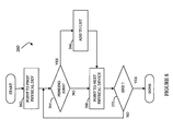
- FIG. 6 is a flow chart that illustrates steps performed in connection with a disk adaptor calling a read scheduler routine according to an embodiment of the system described herein.
- FIG. 8 is a flow chart that illustrates steps performed in connection with constructing a linked list of physical devices according to an embodiment of the system described herein.
- FIG. 10 is a flow chart illustrating steps performed in connection with calculating values for a logical device used in connection with scheduling according to an embodiment of the system described herein.
- FIG. 12 is a flow chart illustrating steps performed in connection with calculating additional values for a physical device used in connection with scheduling according to an embodiment of the system described herein.
- a diagram 20 shows a plurality of hosts 22 a - 22 c coupled to a data storage device 24 .
- Each of the hosts 22 a - 22 c may be coupled using any one of a number of appropriate connection types, including, without limitation, Fibre Channel, ESCON, SCSI, and FICON.
- the data storage device 24 includes an internal memory 26 that facilitates operation of the storage device 24 as described elsewhere herein.
- the data storage device also includes a plurality of host adaptors (HA's) 28 a - 28 c that handle reading and writing of data between the hosts 22 a - 22 c and the storage device 24 .
- HA's host adaptors
- the DA 38 b exchanges data with and controls the disks 36 b - 36 b ′′ and the DA 38 c exchanges data with and controls the disks 36 c - 36 c ′′. It is possible for each of the DA's 38 a - 38 c to control any number of disks. However, in some embodiments, a maximum number may be imposed.
- One or more internal logical data path(s) exist between the DA's 38 a - 38 c , the HA's 28 a - 28 c , the RA's 32 a - 32 c , and the memory 26 .
- one or more internal busses and/or communication modules may be used.
- the memory 26 may be used to facilitate data transferred between the DA's 38 a - 38 c , the HA's 28 a - 28 c and the RA's 32 a - 32 c .
- the memory 26 may contain tasks (jobs) that are to be performed by one or more of the DA's 38 a - 38 c , the HA's 28 a - 28 c and the RA's 32 a - 32 c , and a cache for data fetched from one or more of the disks 36 .
- jobs tasks that are to be performed by one or more of the DA's 38 a - 38 c , the HA's 28 a - 28 c and the RA's 32 a - 32 c , and a cache for data fetched from one or more of the disks 36 .
- jobs tasks
- each of the DA's 38 a - 38 c processes a plurality of jobs (work requests) from different sources, including the HA's 28 a - 28 c , the RA's 32 a - 32 c , and other sources.
- the jobs may include requests to read data from the disks 36 , requests to write data to the disks 36 , etc.
- the DA's 38 a - 38 c receive the requests and then formulate and present appropriate I/O operations to the disks 36 .
- the requests processed by the DA's 38 a - 38 c include read requests, write requests, copy requests, pre-fetch requests, scrub requests, and RAID servicing requests.
- the DA's 38 c - 38 c process these requests and present I/O operations to the disk's 36 in a way that provides appropriate throughput and response time.
- a diagram shows a linked list 100 of physical device records 102 - 104 that may be used to implement the system described herein.
- the linked list 100 may be stored locally on each of the DA's 38 a - 38 c .
- a separate instance of the linked list 100 for each of the DA's 38 a - 38 c may be stored in the memory 26 .
- Each of the physical device records 102 - 104 of the list 100 represents a separate physical device attached to a particular DA.
- each of the physical device records 102 - 104 could represent one of the disk's 36 a , 36 a ′, 36 a ′′.
- the DA 38 a traverses the list 100 to determine which jobs to schedule for the disk's 36 a , 36 a ′, 36 a ′′ using information stored with each of the physical device records 102 - 104 .
- the list 110 corresponds to all of the logical devices of a single physical device, in which case logical device records corresponding to a logical device having no pending jobs (or no pending jobs other than read jobs) may be skipped when traversing the list 110 .
- the list 110 could represent all of the logical devices for the disk 36 a.
- the system described herein traverses the list 110 and uses information stored with each of the logical device records 112 - 114 along with the list 100 and the physical device records 102 - 104 to determine which jobs to schedule.
- the list 110 may be stored locally in each of the DA's 38 a - 36 c or stored in memory 26 .
- a flow chart 140 illustrates steps performed by each of the DA's 38 a - 38 c in connection with traversing the list 100 of physical devices to determine jobs to be scheduled.
- read operations there is a general preference for read operations so that read operations have a higher priority.
- operations may be divided into two classes: read operations and all other operations (e.g., write, copy, scrub, etc.).
- Processing begins at a first step 141 , where a pointer that points to the particular physical device being processed (for which I/O's are being performed) is made to point to the next physical device in the list 100 of physical devices for which there are pending jobs.
- a test step 142 where it is determined if there are any physical devices having jobs to schedule. In some instances, there may be no pending jobs for any of the devices.
- control transfers from the step 142 back to the step 141 to cause a polling loop that waits until there are jobs available to perform.
- control transfers from the test step 142 to a step 144 where a physical skip count variable is updated.
- the physical skip count is part of the data stored in each of the physical device records 102 - 104 of the list 100 and indicates whether a physical device should be skipped for scheduling on a current iteration.
- a physical device with less urgent pending jobs e.g., no read jobs
- physical devices with more urgent pending jobs e.g., read jobs
- the physical skip counter may be a relatively fixed value and there may be a separate iteration counter that keeps track of the number of iterations. In such embodiments, the iteration counter would start at zero and then would be incremented at each iteration. When the iteration counter becomes greater than or equal to the skip counter, then jobs may be scheduled on the physical device and the iteration counter may be reset to zero.
- a test step 146 where it is determined if the physical skip count is zero.
- a non-zero physical skip count indicates that no jobs should be scheduled for the corresponding physical device on the current iteration. If it is determined at the test step 146 that the physical skip count is zero, then control transfers from the test step 146 to a test step 148 where it is determined if a physical run count variable is zero.
- the physical run count is another variable that is stored in each of the physical device records 102 - 104 of the list 100 .
- the physical run count variable represents the number of consecutive operations for the physical device that may be scheduled. Thus, for example, if the run count variable is three, then three consecutive operations for the physical device will be scheduled.
- Consecutively scheduling jobs for the same physical device provides efficiencies for the device in many instances. For example, a number of successive reads to the device may take less time if performed consecutively than if the reads are performed separately with operations for other devices interleaved therebetween.
- the physical run count would always be zero at the step 148 because, as described in more detail elsewhere herein, the physical run count variable is used to keep track of each job that is scheduled. Ideally, on each iteration, the system is able to schedule as many jobs as are indicated by the physical run count and thus decrement the physical run count to zero. However, in some instances, it may not be possible to perform the number of jobs indicated by the physical run count, in which case there may be a non-zero value for the physical run count variable remaining from a previous iteration.
- the physical run count is set equal to the value of a max physical run count variable, another variable of the physical device records 102 - 104 .
- the value of physical run count is set equal to the value of max physical run count. Determination and manipulation of max physical run count is described in more detail elsewhere herein.
- a test step 154 which determines if operation of the DA is blocked.
- the DA may use an operation queue to provide formatted operations thereto which are sent to the corresponding devices (disk drives).
- the test at the step 154 may determine whether or not the queue is full. In other embodiments, there may be other tests/criteria used at the step 154 to determine if the DA may proceed with operations for a particular physical device.
- test step 156 determines if the job(s) to be scheduled are read jobs. Setting and determining whether job(s) to be scheduled are read jobs or are other (i.e., non-read) jobs is described in more detail elsewhere herein. If it is determined at the test step 156 that the job(s) to be scheduled are read jobs, then control transfers from the test step 156 to a step 158 where a read scheduler routine is called. Otherwise, control transfers from the test step 156 to a step 162 where an other operation scheduler routine is called. The read scheduler routine and the other operation scheduler routine are discussed in more detail elsewhere herein.
- a test step 164 where it is determined if the physical run count is zero. Both the read scheduler routine and the other operation scheduler routine manipulate the physical run count according to the number of jobs scheduled so that the physical run count may be changed after calling either routine. If it is determined at the test step 164 that the physical run count is not zero, then control transfers from the test step 164 back to the test step 154 , discussed above, for another iteration. Otherwise, if it is determined at the test step 164 that the physical run count is zero, then control transfers from the test step 164 to the step 141 , discussed above, where the next physical device is selected.
- the test for being blocked at the step 154 determines if the available space in the queue used for operations is less than the physical run count. That is, for example, if the physical run count is three and the available queue space is only enough for two more operations, then it would be determined at the test step 154 that the operation is blocked. In other embodiments, it may be possible to simply determine if there is enough space on the queue for at least one additional operation at the step 154 and to rely on further tests performed in connection with calling the read scheduler routine at the step 158 or calling the other operation scheduler routine at the step 162 .
- a flow chart 180 illustrates steps performed in connection with the DA calling the read scheduler routine at the step 158 of the flow chart 140 of FIG. 5 .
- Processing begins at a first step 182 where it is determined if there are any logical devices to process (i.e., any logical devices with pending jobs). If not, then processing is complete. Otherwise, control transfers from the step 182 to a step 184 where a pointer being used to iterate through logical devices having pending read jobs is set to point to the next logical device. Following the step 184 is a step 186 where it is determined if the pointer has reached an end of a list of logical devices having pending reads.
- pending reads are kept track of using a bitmap table of logical devices for a physical device, where a bit is set to one value of a logical device has at least one pending read and set to another value otherwise.
- the pointer points to bits of the bit map.
- a step 192 where the pointer that iterates through the logical devices having pending reads associated therewith is made to point to a first logical device having a pending read.
- a test step 194 which determines if the value of a logical run count variable associated with the logical device being processed is zero.
- a separate logical run count variable is associated with each of the logical devices and is used to keep track of the run count for a logical device in a manner similar to use of the physical run count variable, discussed above.
- the logical run count would always be zero at the step 194 , but in some cases the logical run count may be something other than zero due to jobs that could not be scheduled at a previous iteration.
- the read operation is generated at the step 202 by formatting an appropriate command that may be sent to one of the disk's 36 .
- the command may specify a particular physical cylinder, sector, and block to transfer directly into a set of memory locations in the memory 26 .
- the actual format of the command generated at the step 202 depends upon the specific types of devices that are coupled to the DA and perhaps even also to the type of connection between the DA and the devices.
- the steps 194 , 194 , 206 may be eliminated and, at the step 204 , only the physical run count variable would be decremented. Note, however, that it is possible to obtain the same result by setting max logical run count to one in connection with anticipating scheduling a read operation.
- max logical run count is set to one in connection with anticipating scheduling a read operation.
- a test step 228 which determines if the logical skip counter equals zero. If not, then control transfers from the step 228 back to the step 222 to select another logical device for performing operations thereon. Otherwise, control transfers from the step 228 to a test step 232 which determines if the logical run counter is zero. If so, then control transfers from the test step 232 to a step 234 which sets the logical run counter in a manner similar to setting the logical run counter at the step 196 of the flow chart 180 of FIG. 6 . Following the step 234 , or following the step 232 if the logical run counter is not zero, is a step 236 which determines if the proposed operation is blocked. The test at the step 236 is like the test at the step 198 of the flow chart 180 of FIG. 6 .
- step 242 where the logical run counter and the corresponding physical run counter are both decremented.
- the amount that the run counters are decremented at the step 242 is the number of operations generated at the step 238 (i.e., one operation at a time or multiple operations scheduled at the same time).
- a test step 244 which determines if the logical run counter is zero. If so, then processing is complete. Otherwise, control transfers from the test step 244 back to the step 236 for another iteration.
- a flow chart 260 illustrates steps performed by a DA in connection with the step 188 of the flow chart 180 of FIG. 6 .
- values used for scheduling like max physical run count and other values, are updated and the lists 100 , 110 are reconfigured, if necessary, to add any logical devices and/or physical devices that have received one or more pending jobs since the previous iteration and to remove any logical devices and/or physical devices for which there are no longer any pending jobs.
- the flow chart 260 illustrates steps performed in connection with reconfiguring the list 100 of physical devices. Note however that, as discussed above, it is possible to reconfigure the lists 100 , 110 and recalculate values periodically independent of any scheduling iterations, in which case the step 188 would not exist.
- each bit map corresponds to a particular operation (e.g., read, write, copy) and each bit of each bit map corresponds to a particular logical device of the physical device.
- Each bit may be set to one value if there are any pending jobs and to another value otherwise.
- the test at the step 264 determines if any bits of any of the bit maps indicate the presence of pending jobs.
- step 264 If it is determined at the step 264 that there is at least one pending job for a physical device, then control transfers from the step 264 to a step 266 where a physical device record corresponding to the physical device is added to the list 100 . Following the step 266 , or following the step 264 if there are no pending jobs for a physical device, is a step 268 where the pointer used to iterate through all of the physical devices of a DA is incremented to point to the next physical device. Following the step 268 is a test step 272 where it is determined if the pointer has reached the end of the list of physical devices for the DA (i.e., all of the physical devices for a DA have been examined). If so, then processing is complete. Otherwise, control transfers from the step 272 back to the step 264 for another iteration.
- a flow chart 300 illustrates steps performed in connection with the step 188 of the flow chart 180 of FIG. 6 .
- the flow chart 300 illustrates steps performed in connection with reconfiguring the list 110 of physical devices and recalculating values used for scheduling.
- Processing begins at a first step 302 to initialize a pointer used to iterate through all physical devices that have pending jobs (i.e., the list 100 constructed according to the flow chart 260 of FIG. 8 ).
- the list 100 is used so that the pointer is set to point to the first physical device record of the list 100 at the step 302 .
- a step 304 where it is determined if the end of the list 100 has been reached. If not, then control transfers from the step 304 to a step 306 where another pointer, used to iterate through all of the logical devices of a physical device, is initialized to point to a first logical device of all of the logical devices.
- a test step 308 where it is determined if the end of the list of all logical devices has been reached (i.e., if all of the logical devices corresponding to a particular physical device have been processed). If not, then control transfers from the step 308 to a test step 312 where it is determined if there are any pending jobs for the logical device being processed. If so, then control transfers from the step 312 to a step 314 where values used for scheduling are calculated for the logical device. Calculations at the step 314 are described in more detail hereinafter. Following the step 314 is a test step 316 where it is determined if all of the pending jobs for a logical device are read only.
- the system keeps track of logical devices having pending read jobs using a bit map table where each bit corresponds to a logical device and is set to a particular value if there are any pending reads and set to another value otherwise.
- the bit map may be examined to determine if there are pending reads for a logical device and the list 110 may be used for logical devices having pending jobs other than reads.
- other techniques may be used, including providing logical device records for all logical devices having any pending jobs (read or otherwise) on to the list 110 or not using any list at all but, instead, relying on one or more bit maps like the read bit map described above.
- step 322 Following the step 318 , or following the step 316 if the only pending job(s) for a logical device are reads is a step 322 where the pointer used to iterate through the logical devices is incremented to point to a next logical device. Note that the step 322 is also reached from the step 312 if there are not any pending jobs for a logical device. Following the step 322 , control transfers back to the test step 308 , described above, where it is determined if all of the logical devices for a physical device have been processed.
- step 308 If it is determined at the step 308 that all of the logical devices corresponding to a physical device have been processed, then control transfers from the step 308 to a step 324 , where values associated with the physical device and used for scheduling, like max physical run count, are calculated. Calculating values at the step 324 is discussed in more detail elsewhere herein. Following the step 324 is a step 326 where the pointer that iterates through the list 100 of physical devices with pending jobs is incremented to point to the next physical device (i.e., the next one of the physical device records 102 - 104 ).
- system described herein includes systems that use any one or more of a number of techniques for determining logical scheduling variables.
- a flow chart 340 illustrates steps performed in connection with the step 314 of the flow chart 300 of FIG. 9 where values used for scheduling are calculated. Processing begins at a first step 342 where a value for a variable, logical other urgency, is calculated.
- the logical other urgency variable indicates the number of jobs, other than reads, that are pending for a logical device.
- the value for logical other urgency may be capped to a particular value, such as four.
- a test step 344 where it is determined if there are any pending reads for the logical device. If so, then control transfers from the step 344 to a step 346 where the value of a variable, logical urgency, is set to a predetermined maximum value, such as four.
- a step 352 where the value of the logical skip count variable (used for scheduling, as discussed elsewhere herein) is set to zero. Following the step 352 , processing is complete.
- step 344 If it is determined at the step 344 that none of the pending jobs for the logical device are reads, then control transfers from the step 344 to a step 354 , where the value of the logical urgency variable is set equal to the value of the logical other urgency variable that was set at the step 342 . Following the step 354 is a step 356 where the value of logical max run count is set equal to the value of the logical urgency variable. Following the step 356 is a step 358 where the logical skip count variable is set equal to a maximum value (e.g., four) minus the value of the logical max run count variable. Following the step 358 , processing is complete.
- a maximum value e.g., four
- a flow chart 380 illustrates steps performed in connection with the step 324 of the flow chart 300 of FIG. 9 where variables used for scheduling and associated with physical devices are determined.
- Processing begins at a first step 382 where a variable that represents a total load for a physical device, physical total load, is calculated.
- physical total load is calculated by summing the number of logical devices at each urgency level multiplied by the urgency level (e.g., number of devices with logical device urgency equal to four times four plus the number of devices with urgency level of three times three, etc.).
- the determination is provided by performing the above-referenced calculation only for the values of logical other urgency and then adding to that result the total number of pending read jobs for all the logical devices.
- step 384 a value for another variable, physical normalized total load, is determined.
- physical normalized total load is determined using the following table:
- step 386 a value for a variable, physical other load, is calculated.
- physical other load is calculated like calculating physical total load at the step 382 , without taking into account any load or urgency caused by pending read jobs.
- step 388 a value for a variable physical normalized other load is determined.
- physical normalized other load may be determined using the same table that was used at the step 384 to calculate physical normalized total load. In other embodiments, a different technique may be used.
- the sequence number represents a number that is incremented (modulo fifteen) on each scheduling iteration.
- sequence number represents a number that is incremented (modulo fifteen) on each scheduling iteration.
- other appropriate techniques may be used to determine whether to schedule reads or other pending jobs.
- the relative proportion of other operations to reads varies according to the number of pending other operations for a physical device.
- a flow chart 400 illustrates steps performed in connection with calculating remaining scheduling variables for a physical device at the step 328 of the flow chart 300 of FIG. 9 .
- Processing begins at a first step 402 , where a value for a variable, DA total load value, is calculated.
- DA total load value is the sum of physical total load value for all of the physical devices associated with the DA.
- a step 404 where a DA normalized total load is calculated.
- the DA normalized total load may be calculated using the following table:
- step 406 the value for the physical max run count variable (used for scheduling, as discussed elsewhere herein) is calculated.
- the physical max run count variable may be determined using the following table:
- the physical skip count variable may be set by subtracting, from a constant value (e.g., four), the maximum logical urgency level for any of the logical devices of the physical device.
- a constant value e.g., four
- the maximum logical urgency level for any of the logical devices of the physical device.
- other appropriate techniques may be used.
Abstract
Description
physical skip count=min(zero,physical skip count−one).
logical skip counter=min(zero,logical skip counter−one)
| physical total load | physical normalized total load | ||
| <4 | 1 | ||
| 4~16 | 2 | ||
| 16~32 | 3 | ||
| 32~64 | 4 | ||
| 64~128 | 5 | ||
| 128~256 | 6 | ||
| 2565~512 | 7 | ||
| >512 | 8 | ||
| 0 | 1 | 2 | 3 | 4 | 5 | 6 | 7 | 8 | 9 | 10 | 11 | 12 | 13 | 14 | |
| 1 | r | r | r | r | o | r | r | r | r | o | r | r | r | r | o |
| 2 | r | r | o | r | r | o | r | r | o | r | r | o | r | r | o |
| 3 | r | r | o | r | r | o | o | r | r | o | r | r | o | o | r |
| 4 | r | o | r | o | r | o | r | o | r | o | r | o | r | o | r |
| 5 | r | o | r | o | r | o | r | o | r | o | r | o | r | o | r |
| 6 | r | o | r | o | r | o | r | o | r | o | r | o | r | o | r |
| 7 | r | o | r | o | r | o | r | o | r | o | r | o | r | o | r |
| 8 | r | o | r | o | r | o | r | o | r | o | r | o | r | o | r |
where the far left column represents the value of physical other normalized load, the top row represents the value of a sequence number, and “r” and “o” represent scheduling reads or scheduling other jobs, respectively. The sequence number represents a number that is incremented (modulo fifteen) on each scheduling iteration. Of course, other appropriate techniques may be used to determine whether to schedule reads or other pending jobs. In an embodiment herein, the relative proportion of other operations to reads varies according to the number of pending other operations for a physical device.
| DA total load | DA normalized total load | ||
| <40 | 1 | ||
| 40~160 | 2 | ||
| 160~320 | 3 | ||
| 320~640 | 4 | ||
| 640~1280 | 5 | ||
| 1280~2560 | 6 | ||
| 2560~5120 | 7 | ||
| >5120 | 8 | ||
| 1 | 2 | 3 | 4 | 5 | 6 | 7 | 8 | |
| 1 | 1 | 1 | 1 | 1 | 1 | 1 | 1 | 1 |
| 2 | 4 | 4 | 4 | 4 | 5 | 5 | 5 | 5 |
| 3 | 5 | 5 | 5 | 5 | 6 | 6 | 6 | 6 |
| 4 | 6 | 6 | 6 | 6 | 8 | 8 | 10 | 10 |
| 5 | 6 | 6 | 8 | 8 | 10 | 10 | 12 | 12 |
| 6 | 6 | 8 | 10 | 10 | 12 | 14 | 14 | 16 |
| 7 | 8 | 8 | 10 | 12 | 12 | 14 | 16 | 16 |
| 8 | 8 | 10 | 12 | 14 | 14 | 16 | 16 | 16 |
where the top row represents possible values for DA normalized load level, the far left column represents values for physical normalized load level, and the remainder of the cells of the table represent values for physical max run count. Of course, other appropriate techniques may be used.
Claims (14)
Priority Applications (1)
| Application Number | Priority Date | Filing Date | Title |
|---|---|---|---|
| US11/154,234 US8423728B1 (en) | 2005-06-16 | 2005-06-16 | Physical based scheduler using run count and skip count values |
Applications Claiming Priority (1)
| Application Number | Priority Date | Filing Date | Title |
|---|---|---|---|
| US11/154,234 US8423728B1 (en) | 2005-06-16 | 2005-06-16 | Physical based scheduler using run count and skip count values |
Publications (1)
| Publication Number | Publication Date |
|---|---|
| US8423728B1 true US8423728B1 (en) | 2013-04-16 |
Family
ID=48049276
Family Applications (1)
| Application Number | Title | Priority Date | Filing Date |
|---|---|---|---|
| US11/154,234 Active 2029-03-19 US8423728B1 (en) | 2005-06-16 | 2005-06-16 | Physical based scheduler using run count and skip count values |
Country Status (1)
| Country | Link |
|---|---|
| US (1) | US8423728B1 (en) |
Cited By (1)
| Publication number | Priority date | Publication date | Assignee | Title |
|---|---|---|---|---|
| US20180300176A1 (en) * | 2017-04-17 | 2018-10-18 | Red Hat, Inc. | Self-programmable and self-tunable resource scheduler for jobs in cloud computing |
Citations (10)
| Publication number | Priority date | Publication date | Assignee | Title |
|---|---|---|---|---|
| US5206939A (en) | 1990-09-24 | 1993-04-27 | Emc Corporation | System and method for disk mapping and data retrieval |
| US5778394A (en) | 1996-12-23 | 1998-07-07 | Emc Corporation | Space reclamation system and method for use in connection with tape logging system |
| US5845147A (en) | 1996-03-19 | 1998-12-01 | Emc Corporation | Single lock command for an I/O storage system that performs both locking and I/O data operation |
| US5857208A (en) | 1996-05-31 | 1999-01-05 | Emc Corporation | Method and apparatus for performing point in time backup operation in a computer system |
| US5918020A (en) * | 1997-02-28 | 1999-06-29 | International Business Machines Corporation | Data processing system and method for pacing information transfers in a communications network |
| US5987031A (en) * | 1997-05-22 | 1999-11-16 | Integrated Device Technology, Inc. | Method for fair dynamic scheduling of available bandwidth rate (ABR) service under asynchronous transfer mode (ATM) |
| US20030063562A1 (en) * | 2001-09-21 | 2003-04-03 | Terago Communications, Inc. | Programmable multi-service queue scheduler |
| US6665740B1 (en) * | 1999-11-12 | 2003-12-16 | Emc Corporation | Logical volume selection in a probability-based job scheduler |
| US7099273B2 (en) * | 2001-04-12 | 2006-08-29 | Bytemobile, Inc. | Data transport acceleration and management within a network communication system |
| US7809850B2 (en) * | 2002-06-06 | 2010-10-05 | International Business Machines Corporation | Digital content delivery system, digital content delivery method, program for executing the method, computer readable recording medium storing thereon the program, and server and client for it |
-
2005
- 2005-06-16 US US11/154,234 patent/US8423728B1/en active Active
Patent Citations (10)
| Publication number | Priority date | Publication date | Assignee | Title |
|---|---|---|---|---|
| US5206939A (en) | 1990-09-24 | 1993-04-27 | Emc Corporation | System and method for disk mapping and data retrieval |
| US5845147A (en) | 1996-03-19 | 1998-12-01 | Emc Corporation | Single lock command for an I/O storage system that performs both locking and I/O data operation |
| US5857208A (en) | 1996-05-31 | 1999-01-05 | Emc Corporation | Method and apparatus for performing point in time backup operation in a computer system |
| US5778394A (en) | 1996-12-23 | 1998-07-07 | Emc Corporation | Space reclamation system and method for use in connection with tape logging system |
| US5918020A (en) * | 1997-02-28 | 1999-06-29 | International Business Machines Corporation | Data processing system and method for pacing information transfers in a communications network |
| US5987031A (en) * | 1997-05-22 | 1999-11-16 | Integrated Device Technology, Inc. | Method for fair dynamic scheduling of available bandwidth rate (ABR) service under asynchronous transfer mode (ATM) |
| US6665740B1 (en) * | 1999-11-12 | 2003-12-16 | Emc Corporation | Logical volume selection in a probability-based job scheduler |
| US7099273B2 (en) * | 2001-04-12 | 2006-08-29 | Bytemobile, Inc. | Data transport acceleration and management within a network communication system |
| US20030063562A1 (en) * | 2001-09-21 | 2003-04-03 | Terago Communications, Inc. | Programmable multi-service queue scheduler |
| US7809850B2 (en) * | 2002-06-06 | 2010-10-05 | International Business Machines Corporation | Digital content delivery system, digital content delivery method, program for executing the method, computer readable recording medium storing thereon the program, and server and client for it |
Cited By (2)
| Publication number | Priority date | Publication date | Assignee | Title |
|---|---|---|---|---|
| US20180300176A1 (en) * | 2017-04-17 | 2018-10-18 | Red Hat, Inc. | Self-programmable and self-tunable resource scheduler for jobs in cloud computing |
| US11334391B2 (en) * | 2017-04-17 | 2022-05-17 | Red Hat, Inc. | Self-programmable and self-tunable resource scheduler for jobs in cloud computing |
Similar Documents
| Publication | Publication Date | Title |
|---|---|---|
| US7945731B2 (en) | Method for reading data with storage system, data managing system for storage system and storage system | |
| US6581135B2 (en) | Information storage system for redistributing information to information storage devices when a structure of the information storage devices is changed | |
| US8112596B2 (en) | Management apparatus, management method and storage management system | |
| US7191285B2 (en) | Configuring memory for a RAID storage system | |
| US7536505B2 (en) | Storage system and method for controlling block rearrangement | |
| US7321955B2 (en) | Control device, control method and storage medium recording a control program for controlling write-back schedule of data from cache memory to a plurality of storage devices | |
| JP3541744B2 (en) | Storage subsystem and control method thereof | |
| US6851022B2 (en) | Raid controller and control method thereof | |
| US7996635B2 (en) | Offsite management using disk based tape library and vault system | |
| US7594071B2 (en) | Storage system employing a hierarchical directory section and a cache directory section | |
| US7434012B1 (en) | Techniques for media scrubbing | |
| US6944712B2 (en) | Method and apparatus for mapping storage partitions of storage elements for host systems | |
| US20040123017A1 (en) | Method and apparatus for handling storage requests | |
| JP2002278704A (en) | Method for optimizing processing, computer and storage device | |
| KR20030034577A (en) | Stripping system, mapping and processing method thereof | |
| JP2008146536A (en) | Storage device, and data control method using the same | |
| US8261029B1 (en) | Dynamic balancing of writes between multiple storage devices | |
| US6681291B2 (en) | Storage controller and control method thereof | |
| US6912643B2 (en) | Method of flexibly mapping a number of storage elements into a virtual storage element | |
| US9298394B2 (en) | Data arrangement method and data management system for improving performance using a logical storage volume | |
| US6782444B1 (en) | Digital data storage subsystem including directory for efficiently providing formatting information for stored records | |
| US8751739B1 (en) | Data device spares | |
| US8301851B1 (en) | Consecutive scheduling of jobs for a device using run count values | |
| US8255646B2 (en) | Storage apparatus and logical volume migration method | |
| US8423728B1 (en) | Physical based scheduler using run count and skip count values |
Legal Events
| Date | Code | Title | Description |
|---|---|---|---|
| AS | Assignment |
Owner name: EMC CORPORATION, MASSACHUSETTS Free format text: ASSIGNMENT OF ASSIGNORS INTEREST;ASSIGNORS:YU, RONG;YIN, PENG;IVES, STEPHEN R.;AND OTHERS;SIGNING DATES FROM 20050609 TO 20050615;REEL/FRAME:016702/0881 |
|
| AS | Assignment |
Owner name: EMC CORPORATION, MASSACHUSETTS Free format text: ASSIGNMENT OF ASSIGNORS INTEREST;ASSIGNOR:SADE, GILAD;REEL/FRAME:017352/0913 Effective date: 20051118 |
|
| FEPP | Fee payment procedure |
Free format text: PAYER NUMBER DE-ASSIGNED (ORIGINAL EVENT CODE: RMPN); ENTITY STATUS OF PATENT OWNER: LARGE ENTITY Free format text: PAYOR NUMBER ASSIGNED (ORIGINAL EVENT CODE: ASPN); ENTITY STATUS OF PATENT OWNER: LARGE ENTITY |
|
| STCF | Information on status: patent grant |
Free format text: PATENTED CASE |
|
| AS | Assignment |
Owner name: CREDIT SUISSE AG, CAYMAN ISLANDS BRANCH, AS COLLATERAL AGENT, NORTH CAROLINA Free format text: SECURITY AGREEMENT;ASSIGNORS:ASAP SOFTWARE EXPRESS, INC.;AVENTAIL LLC;CREDANT TECHNOLOGIES, INC.;AND OTHERS;REEL/FRAME:040134/0001 Effective date: 20160907 Owner name: THE BANK OF NEW YORK MELLON TRUST COMPANY, N.A., AS NOTES COLLATERAL AGENT, TEXAS Free format text: SECURITY AGREEMENT;ASSIGNORS:ASAP SOFTWARE EXPRESS, INC.;AVENTAIL LLC;CREDANT TECHNOLOGIES, INC.;AND OTHERS;REEL/FRAME:040136/0001 Effective date: 20160907 Owner name: CREDIT SUISSE AG, CAYMAN ISLANDS BRANCH, AS COLLAT Free format text: SECURITY AGREEMENT;ASSIGNORS:ASAP SOFTWARE EXPRESS, INC.;AVENTAIL LLC;CREDANT TECHNOLOGIES, INC.;AND OTHERS;REEL/FRAME:040134/0001 Effective date: 20160907 Owner name: THE BANK OF NEW YORK MELLON TRUST COMPANY, N.A., A Free format text: SECURITY AGREEMENT;ASSIGNORS:ASAP SOFTWARE EXPRESS, INC.;AVENTAIL LLC;CREDANT TECHNOLOGIES, INC.;AND OTHERS;REEL/FRAME:040136/0001 Effective date: 20160907 |
|
| AS | Assignment |
Owner name: EMC IP HOLDING COMPANY LLC, MASSACHUSETTS Free format text: ASSIGNMENT OF ASSIGNORS INTEREST;ASSIGNOR:EMC CORPORATION;REEL/FRAME:040203/0001 Effective date: 20160906 |
|
| FPAY | Fee payment |
Year of fee payment: 4 |
|
| AS | Assignment |
Owner name: THE BANK OF NEW YORK MELLON TRUST COMPANY, N.A., T Free format text: SECURITY AGREEMENT;ASSIGNORS:CREDANT TECHNOLOGIES, INC.;DELL INTERNATIONAL L.L.C.;DELL MARKETING L.P.;AND OTHERS;REEL/FRAME:049452/0223 Effective date: 20190320 Owner name: THE BANK OF NEW YORK MELLON TRUST COMPANY, N.A., TEXAS Free format text: SECURITY AGREEMENT;ASSIGNORS:CREDANT TECHNOLOGIES, INC.;DELL INTERNATIONAL L.L.C.;DELL MARKETING L.P.;AND OTHERS;REEL/FRAME:049452/0223 Effective date: 20190320 |
|
| AS | Assignment |
Owner name: THE BANK OF NEW YORK MELLON TRUST COMPANY, N.A., TEXAS Free format text: SECURITY AGREEMENT;ASSIGNORS:CREDANT TECHNOLOGIES INC.;DELL INTERNATIONAL L.L.C.;DELL MARKETING L.P.;AND OTHERS;REEL/FRAME:053546/0001 Effective date: 20200409 |
|
| MAFP | Maintenance fee payment |
Free format text: PAYMENT OF MAINTENANCE FEE, 8TH YEAR, LARGE ENTITY (ORIGINAL EVENT CODE: M1552); ENTITY STATUS OF PATENT OWNER: LARGE ENTITY Year of fee payment: 8 |
|
| AS | Assignment |
Owner name: WYSE TECHNOLOGY L.L.C., CALIFORNIA Free format text: RELEASE BY SECURED PARTY;ASSIGNOR:CREDIT SUISSE AG, CAYMAN ISLANDS BRANCH;REEL/FRAME:058216/0001 Effective date: 20211101 Owner name: SCALEIO LLC, MASSACHUSETTS Free format text: RELEASE BY SECURED PARTY;ASSIGNOR:CREDIT SUISSE AG, CAYMAN ISLANDS BRANCH;REEL/FRAME:058216/0001 Effective date: 20211101 Owner name: MOZY, INC., WASHINGTON Free format text: RELEASE BY SECURED PARTY;ASSIGNOR:CREDIT SUISSE AG, CAYMAN ISLANDS BRANCH;REEL/FRAME:058216/0001 Effective date: 20211101 Owner name: MAGINATICS LLC, CALIFORNIA Free format text: RELEASE BY SECURED PARTY;ASSIGNOR:CREDIT SUISSE AG, CAYMAN ISLANDS BRANCH;REEL/FRAME:058216/0001 Effective date: 20211101 Owner name: FORCE10 NETWORKS, INC., CALIFORNIA Free format text: RELEASE BY SECURED PARTY;ASSIGNOR:CREDIT SUISSE AG, CAYMAN ISLANDS BRANCH;REEL/FRAME:058216/0001 Effective date: 20211101 Owner name: EMC IP HOLDING COMPANY LLC, TEXAS Free format text: RELEASE BY SECURED PARTY;ASSIGNOR:CREDIT SUISSE AG, CAYMAN ISLANDS BRANCH;REEL/FRAME:058216/0001 Effective date: 20211101 Owner name: EMC CORPORATION, MASSACHUSETTS Free format text: RELEASE BY SECURED PARTY;ASSIGNOR:CREDIT SUISSE AG, CAYMAN ISLANDS BRANCH;REEL/FRAME:058216/0001 Effective date: 20211101 Owner name: DELL SYSTEMS CORPORATION, TEXAS Free format text: RELEASE BY SECURED PARTY;ASSIGNOR:CREDIT SUISSE AG, CAYMAN ISLANDS BRANCH;REEL/FRAME:058216/0001 Effective date: 20211101 Owner name: DELL SOFTWARE INC., CALIFORNIA Free format text: RELEASE BY SECURED PARTY;ASSIGNOR:CREDIT SUISSE AG, CAYMAN ISLANDS BRANCH;REEL/FRAME:058216/0001 Effective date: 20211101 Owner name: DELL PRODUCTS L.P., TEXAS Free format text: RELEASE BY SECURED PARTY;ASSIGNOR:CREDIT SUISSE AG, CAYMAN ISLANDS BRANCH;REEL/FRAME:058216/0001 Effective date: 20211101 Owner name: DELL MARKETING L.P., TEXAS Free format text: RELEASE BY SECURED PARTY;ASSIGNOR:CREDIT SUISSE AG, CAYMAN ISLANDS BRANCH;REEL/FRAME:058216/0001 Effective date: 20211101 Owner name: DELL INTERNATIONAL, L.L.C., TEXAS Free format text: RELEASE BY SECURED PARTY;ASSIGNOR:CREDIT SUISSE AG, CAYMAN ISLANDS BRANCH;REEL/FRAME:058216/0001 Effective date: 20211101 Owner name: DELL USA L.P., TEXAS Free format text: RELEASE BY SECURED PARTY;ASSIGNOR:CREDIT SUISSE AG, CAYMAN ISLANDS BRANCH;REEL/FRAME:058216/0001 Effective date: 20211101 Owner name: CREDANT TECHNOLOGIES, INC., TEXAS Free format text: RELEASE BY SECURED PARTY;ASSIGNOR:CREDIT SUISSE AG, CAYMAN ISLANDS BRANCH;REEL/FRAME:058216/0001 Effective date: 20211101 Owner name: AVENTAIL LLC, CALIFORNIA Free format text: RELEASE BY SECURED PARTY;ASSIGNOR:CREDIT SUISSE AG, CAYMAN ISLANDS BRANCH;REEL/FRAME:058216/0001 Effective date: 20211101 Owner name: ASAP SOFTWARE EXPRESS, INC., ILLINOIS Free format text: RELEASE BY SECURED PARTY;ASSIGNOR:CREDIT SUISSE AG, CAYMAN ISLANDS BRANCH;REEL/FRAME:058216/0001 Effective date: 20211101 |
|
| AS | Assignment |
Owner name: SCALEIO LLC, MASSACHUSETTS Free format text: RELEASE OF SECURITY INTEREST IN PATENTS PREVIOUSLY RECORDED AT REEL/FRAME (040136/0001);ASSIGNOR:THE BANK OF NEW YORK MELLON TRUST COMPANY, N.A., AS NOTES COLLATERAL AGENT;REEL/FRAME:061324/0001 Effective date: 20220329 Owner name: EMC IP HOLDING COMPANY LLC (ON BEHALF OF ITSELF AND AS SUCCESSOR-IN-INTEREST TO MOZY, INC.), TEXAS Free format text: RELEASE OF SECURITY INTEREST IN PATENTS PREVIOUSLY RECORDED AT REEL/FRAME (040136/0001);ASSIGNOR:THE BANK OF NEW YORK MELLON TRUST COMPANY, N.A., AS NOTES COLLATERAL AGENT;REEL/FRAME:061324/0001 Effective date: 20220329 Owner name: EMC CORPORATION (ON BEHALF OF ITSELF AND AS SUCCESSOR-IN-INTEREST TO MAGINATICS LLC), MASSACHUSETTS Free format text: RELEASE OF SECURITY INTEREST IN PATENTS PREVIOUSLY RECORDED AT REEL/FRAME (040136/0001);ASSIGNOR:THE BANK OF NEW YORK MELLON TRUST COMPANY, N.A., AS NOTES COLLATERAL AGENT;REEL/FRAME:061324/0001 Effective date: 20220329 Owner name: DELL MARKETING CORPORATION (SUCCESSOR-IN-INTEREST TO FORCE10 NETWORKS, INC. AND WYSE TECHNOLOGY L.L.C.), TEXAS Free format text: RELEASE OF SECURITY INTEREST IN PATENTS PREVIOUSLY RECORDED AT REEL/FRAME (040136/0001);ASSIGNOR:THE BANK OF NEW YORK MELLON TRUST COMPANY, N.A., AS NOTES COLLATERAL AGENT;REEL/FRAME:061324/0001 Effective date: 20220329 Owner name: DELL PRODUCTS L.P., TEXAS Free format text: RELEASE OF SECURITY INTEREST IN PATENTS PREVIOUSLY RECORDED AT REEL/FRAME (040136/0001);ASSIGNOR:THE BANK OF NEW YORK MELLON TRUST COMPANY, N.A., AS NOTES COLLATERAL AGENT;REEL/FRAME:061324/0001 Effective date: 20220329 Owner name: DELL INTERNATIONAL L.L.C., TEXAS Free format text: RELEASE OF SECURITY INTEREST IN PATENTS PREVIOUSLY RECORDED AT REEL/FRAME (040136/0001);ASSIGNOR:THE BANK OF NEW YORK MELLON TRUST COMPANY, N.A., AS NOTES COLLATERAL AGENT;REEL/FRAME:061324/0001 Effective date: 20220329 Owner name: DELL USA L.P., TEXAS Free format text: RELEASE OF SECURITY INTEREST IN PATENTS PREVIOUSLY RECORDED AT REEL/FRAME (040136/0001);ASSIGNOR:THE BANK OF NEW YORK MELLON TRUST COMPANY, N.A., AS NOTES COLLATERAL AGENT;REEL/FRAME:061324/0001 Effective date: 20220329 Owner name: DELL MARKETING L.P. (ON BEHALF OF ITSELF AND AS SUCCESSOR-IN-INTEREST TO CREDANT TECHNOLOGIES, INC.), TEXAS Free format text: RELEASE OF SECURITY INTEREST IN PATENTS PREVIOUSLY RECORDED AT REEL/FRAME (040136/0001);ASSIGNOR:THE BANK OF NEW YORK MELLON TRUST COMPANY, N.A., AS NOTES COLLATERAL AGENT;REEL/FRAME:061324/0001 Effective date: 20220329 Owner name: DELL MARKETING CORPORATION (SUCCESSOR-IN-INTEREST TO ASAP SOFTWARE EXPRESS, INC.), TEXAS Free format text: RELEASE OF SECURITY INTEREST IN PATENTS PREVIOUSLY RECORDED AT REEL/FRAME (040136/0001);ASSIGNOR:THE BANK OF NEW YORK MELLON TRUST COMPANY, N.A., AS NOTES COLLATERAL AGENT;REEL/FRAME:061324/0001 Effective date: 20220329 |
|
| AS | Assignment |
Owner name: SCALEIO LLC, MASSACHUSETTS Free format text: RELEASE OF SECURITY INTEREST IN PATENTS PREVIOUSLY RECORDED AT REEL/FRAME (045455/0001);ASSIGNOR:THE BANK OF NEW YORK MELLON TRUST COMPANY, N.A., AS NOTES COLLATERAL AGENT;REEL/FRAME:061753/0001 Effective date: 20220329 Owner name: EMC IP HOLDING COMPANY LLC (ON BEHALF OF ITSELF AND AS SUCCESSOR-IN-INTEREST TO MOZY, INC.), TEXAS Free format text: RELEASE OF SECURITY INTEREST IN PATENTS PREVIOUSLY RECORDED AT REEL/FRAME (045455/0001);ASSIGNOR:THE BANK OF NEW YORK MELLON TRUST COMPANY, N.A., AS NOTES COLLATERAL AGENT;REEL/FRAME:061753/0001 Effective date: 20220329 Owner name: EMC CORPORATION (ON BEHALF OF ITSELF AND AS SUCCESSOR-IN-INTEREST TO MAGINATICS LLC), MASSACHUSETTS Free format text: RELEASE OF SECURITY INTEREST IN PATENTS PREVIOUSLY RECORDED AT REEL/FRAME (045455/0001);ASSIGNOR:THE BANK OF NEW YORK MELLON TRUST COMPANY, N.A., AS NOTES COLLATERAL AGENT;REEL/FRAME:061753/0001 Effective date: 20220329 Owner name: DELL MARKETING CORPORATION (SUCCESSOR-IN-INTEREST TO FORCE10 NETWORKS, INC. AND WYSE TECHNOLOGY L.L.C.), TEXAS Free format text: RELEASE OF SECURITY INTEREST IN PATENTS PREVIOUSLY RECORDED AT REEL/FRAME (045455/0001);ASSIGNOR:THE BANK OF NEW YORK MELLON TRUST COMPANY, N.A., AS NOTES COLLATERAL AGENT;REEL/FRAME:061753/0001 Effective date: 20220329 Owner name: DELL PRODUCTS L.P., TEXAS Free format text: RELEASE OF SECURITY INTEREST IN PATENTS PREVIOUSLY RECORDED AT REEL/FRAME (045455/0001);ASSIGNOR:THE BANK OF NEW YORK MELLON TRUST COMPANY, N.A., AS NOTES COLLATERAL AGENT;REEL/FRAME:061753/0001 Effective date: 20220329 Owner name: DELL INTERNATIONAL L.L.C., TEXAS Free format text: RELEASE OF SECURITY INTEREST IN PATENTS PREVIOUSLY RECORDED AT REEL/FRAME (045455/0001);ASSIGNOR:THE BANK OF NEW YORK MELLON TRUST COMPANY, N.A., AS NOTES COLLATERAL AGENT;REEL/FRAME:061753/0001 Effective date: 20220329 Owner name: DELL USA L.P., TEXAS Free format text: RELEASE OF SECURITY INTEREST IN PATENTS PREVIOUSLY RECORDED AT REEL/FRAME (045455/0001);ASSIGNOR:THE BANK OF NEW YORK MELLON TRUST COMPANY, N.A., AS NOTES COLLATERAL AGENT;REEL/FRAME:061753/0001 Effective date: 20220329 Owner name: DELL MARKETING L.P. (ON BEHALF OF ITSELF AND AS SUCCESSOR-IN-INTEREST TO CREDANT TECHNOLOGIES, INC.), TEXAS Free format text: RELEASE OF SECURITY INTEREST IN PATENTS PREVIOUSLY RECORDED AT REEL/FRAME (045455/0001);ASSIGNOR:THE BANK OF NEW YORK MELLON TRUST COMPANY, N.A., AS NOTES COLLATERAL AGENT;REEL/FRAME:061753/0001 Effective date: 20220329 Owner name: DELL MARKETING CORPORATION (SUCCESSOR-IN-INTEREST TO ASAP SOFTWARE EXPRESS, INC.), TEXAS Free format text: RELEASE OF SECURITY INTEREST IN PATENTS PREVIOUSLY RECORDED AT REEL/FRAME (045455/0001);ASSIGNOR:THE BANK OF NEW YORK MELLON TRUST COMPANY, N.A., AS NOTES COLLATERAL AGENT;REEL/FRAME:061753/0001 Effective date: 20220329 |