BACKGROUND
1. Technical Field
The disclosure generally relates to camera assemblies, and more particularly to a camera assembly capable of adjusting an angle of a camera.
2. Description of Related Art
Generally, a camera of an internet protocol (IP) phone is fixed to a base of the IP phone. To adjust the camera, an user can either manually adjust a stand of the IP phone or move the base of the IP phone to make the camera aim at a target image. However, this manual method is cumbersome and ineffective for more precise measurements.
Therefore, a need exists in the industry to overcome the described limitations.
BRIEF DESCRIPTION OF THE DRAWINGS
Many aspects of the present embodiments can be better understood with reference to the following drawings. The components in the drawings are not necessarily drawn to scale, the emphasis instead being placed upon clearly illustrating the principles of the present embodiments. Moreover, in the drawings, all the views are schematic, and like reference numerals designate corresponding parts throughout the several views.
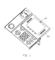
FIG. 1 is a perspective, isometric view of an electronic device of an exemplary embodiment of the disclosure, in which the electronic device comprises a camera to shoot a target image.
FIG. 2 is a perspective, isometric view of a camera assembly of the disclosure, in which the camera assembly is mounted in the electronic device of FIG. 1, and the camera rotates around an axis of the second shaft.
FIG. 3 is a disassembled perspective view of FIG. 2.
FIG. 4 is a perspective, isometric view of a base of FIG. 2.
FIG. 5 is a perspective, isometric view of the camera of FIG. 1.
FIG. 6 is a sketching view of a connection relationship between the camera and a first shaft.
FIG. 7 is a perspective, isometric view of the camera assembly of the disclosure, in which the camera rotates around an axis of the first shaft.
DETAILED DESCRIPTION
The disclosure is illustrated by way of example and not by way of limitation in the figures of the accompanying drawings in which like references indicate similar elements. It should be noted that references to “an” or “one” embodiment in this disclosure are not necessarily to the same embodiment, and such references mean at least one.
FIG. 1 is a perspective, isometric view of an electronic device 200 of the disclosure. FIG. 2 is a perspective, isometric view of a camera assembly 100 with an exemplary embodiment of the disclosure. The electronic device 200 comprises a camera 300 to shoot a target image. The camera assembly 100 is mounted in the electronic device 200 to adjust the camera 300 to aim at the target image. In the embodiment, the electronic device 200 is an internet protocol (IP) phone.
The camera assembly 100 comprises a hollow base 10, a first gear 20, a first shaft 30, a second gear 40, a second shaft 50, a driving device 60 and a driving gear 70. The camera 300 is received in the base 10 and rotatably connected to the base 10. One end of the first shaft 30 is fixed with the first gear 20, another end of the first shaft 30 is rotatably connected with the camera 300. One end of the second shaft 50 is fixed with the base 10, another end of the second shaft 50 is fixed with the second gear 40. In the embodiment, the first shaft 30 and the second shaft 50 are perpendicular with each other. The driving device 60 drives the driving gear 70 to engage with the first gear 20 and the second gear 40, respectively, which lead to the camera 300 capable of rotating around an axis A1 of the first shaft 30 and an axis A2 of the second shaft 50, respectively. By this way, the camera 300 is adjusted to aim at the target image.
With reference to FIG. 3 and FIG. 4, the base 10 comprises a first base 11 and a second base 12. The first base 11 and the second base 12 are fixed together by a plurality of bolts 80 to collectively form a receiving space 13 to receive the camera 300. The base 10 defines a first hole 14, a second hole 15 and a groove 16 in an interior wall 17 of the base 10. The first hole 14, the second hole 15 and the groove 16 are all communicating with the receiving space 13.
With reference to FIG. 5, the camera 300 comprises a lens 320 to aim at the target image, and a protruding portion 330 projecting from an exterior surface 350 of the camera 300. The camera 300 defines a receiving hole 310, and a third hole 340 communication with the receiving hole 310. In assembly, the camera 300 is received in the receiving space 13 of the base 10 with the receiving hole 310 of the camera 300 opposite to the first hole 14 of the base 10, the lens 320 of the camera 30 opposite to the second hole 15, and the protruding portion 330 of the camera 30 received in the groove 16 of the base 10 and capable of sliding along the groove 16. By this way, when the camera 300 rotates around the axis A1 of the first shaft 30, the camera 300 can rotate along the groove 16 of the base 10 with the lens 320 of the camera 300 moving toward the second hole 15 of the base 10. When the camera 300 rotates around the axis A2 of the second shaft 50, the camera 300 fails to move relative to the base 10 by engagement of the protruding portion 330 of the camera 300 and the groove 16 of the base 10, which leads to the camera 300 rotating around the axis of the second shaft 50 together with the base 10.
In the embodiment, the protruding portion 320 of the camera 300 is substantially in a shape of an arc, and the center of the arc is located in the axis A1 of the first shaft 30. The camera 300 is substantially in a shape of a ball, and the receiving space 13 is correspondingly ball shaped.
Referring to FIG. 3, the first shaft 30 comprises a first end 31 defining a through hole 311, and a second end 32 fixed with the first gear 20. Referring to FIG. 6, in assembly, the first end 31 passes through the first hole 14 of the base 10 and extends into the receiving hole 310 of the camera 300. One end of a third shaft 90 inserts through the through hole 311 of the first shaft 30 and extends into the third hole 340 of the camera 300, and another end of the third shaft 90 matches with a nut 91. An axis of the third shaft 90 is collinear with that of the second shaft 50. By this way, the camera 300 is fixed with the third shaft 90 and capable of rotating relatively to the first shaft 30 around the axis of the third shaft 90. When the camera 300 rotates around the axis A2 of the second shaft 50 together with the base 10, the third shaft 90 rotates in the through hole 311 of the first shaft 30, which keeps the first shaft 30 quiescence.
With reference to FIG. 7, the driving device 60 comprises an output shaft 61. The driving gear 70 is fixed to the output shaft 61. The driving device 60 controls the output shaft 61 moving by a controlling device (not shown), which lead to the driving gear 70 moving along the output shaft 61 to engage with the first gear 20 and the second gear 40, respectively.
In the embodiment, the driving device 60 is a step motor. The driving gear 70 comprises a first driving gear 71 engaged with the first gear 20, and a second driving gear 72 integrated with the first driving gear 71 and engaged with the second gear 40. The first driving gear 71 and the first gear 20 are umbrella gears, the second driving gear 72 and the second the second gear 40 are spur gears.
In use, to adjust the camera 300 of the electronic device 200, the driving device 60 drives the driving gear 71 to engage with the first gear 20, which lead to the first gear 20 and the first shaft 30 rotating. As a result, the camera 300 rotates around the axis A1 of the first shaft 30, to adjust the angle of the lens 320 right and left. When the driving device 60 drives the second driving gear 72 to engage with the second gear 40, which lead to the second gear 40 and the second shaft 50 rotating, and the camera 300 and the base 10 rotate around the axis A2 of the second shaft 50 together to adjust the angle of the lens 320 up and down. By this way, the lens 320 of the camera 300 aims at the target image with precise measurements effectively.
While the exemplary embodiments have been described, it should be understood that it has been presented by way of example only and not by way of limitation. The breadth and scope of the disclosure should not be limited by the described exemplary embodiments, but only in accordance with the following claims and their equivalents.