US8360541B2 - Reusable paper media with compatibility markings and printer with incompatible media sensor - Google Patents
Reusable paper media with compatibility markings and printer with incompatible media sensor Download PDFInfo
- Publication number
- US8360541B2 US8360541B2 US13/042,944 US201113042944A US8360541B2 US 8360541 B2 US8360541 B2 US 8360541B2 US 201113042944 A US201113042944 A US 201113042944A US 8360541 B2 US8360541 B2 US 8360541B2
- Authority
- US
- United States
- Prior art keywords
- image forming
- media
- image
- forming medium
- sensor
- Prior art date
- Legal status (The legal status is an assumption and is not a legal conclusion. Google has not performed a legal analysis and makes no representation as to the accuracy of the status listed.)
- Active
Links
- 239000000463 material Substances 0.000 claims abstract description 127
- 238000007639 printing Methods 0.000 claims description 35
- 238000000034 method Methods 0.000 claims description 18
- 230000032258 transport Effects 0.000 claims description 18
- 238000005286 illumination Methods 0.000 claims description 5
- 239000000758 substrate Substances 0.000 abstract description 40
- 238000003384 imaging method Methods 0.000 abstract description 31
- 239000010410 layer Substances 0.000 description 33
- 239000000123 paper Substances 0.000 description 33
- 239000000203 mixture Substances 0.000 description 10
- 230000003595 spectral effect Effects 0.000 description 7
- 239000000976 ink Substances 0.000 description 6
- 238000000576 coating method Methods 0.000 description 5
- 230000003287 optical effect Effects 0.000 description 5
- VYPSYNLAJGMNEJ-UHFFFAOYSA-N Silicium dioxide Chemical compound O=[Si]=O VYPSYNLAJGMNEJ-UHFFFAOYSA-N 0.000 description 4
- -1 polyethylene Polymers 0.000 description 3
- 229920000642 polymer Polymers 0.000 description 3
- 230000003213 activating effect Effects 0.000 description 2
- 239000011248 coating agent Substances 0.000 description 2
- 238000004519 manufacturing process Methods 0.000 description 2
- 239000004033 plastic Substances 0.000 description 2
- 229920003023 plastic Polymers 0.000 description 2
- 239000000377 silicon dioxide Substances 0.000 description 2
- 230000001052 transient effect Effects 0.000 description 2
- 239000004695 Polyether sulfone Substances 0.000 description 1
- 239000004698 Polyethylene Substances 0.000 description 1
- 239000004793 Polystyrene Substances 0.000 description 1
- XUIMIQQOPSSXEZ-UHFFFAOYSA-N Silicon Chemical compound [Si] XUIMIQQOPSSXEZ-UHFFFAOYSA-N 0.000 description 1
- 239000000853 adhesive Substances 0.000 description 1
- 230000001070 adhesive effect Effects 0.000 description 1
- 239000011230 binding agent Substances 0.000 description 1
- 230000015572 biosynthetic process Effects 0.000 description 1
- 230000000981 bystander Effects 0.000 description 1
- 239000000919 ceramic Substances 0.000 description 1
- 238000001514 detection method Methods 0.000 description 1
- 238000003618 dip coating Methods 0.000 description 1
- 239000006185 dispersion Substances 0.000 description 1
- 238000001035 drying Methods 0.000 description 1
- 239000000975 dye Substances 0.000 description 1
- 230000007613 environmental effect Effects 0.000 description 1
- 239000004744 fabric Substances 0.000 description 1
- 239000010408 film Substances 0.000 description 1
- 239000007850 fluorescent dye Substances 0.000 description 1
- 239000011521 glass Substances 0.000 description 1
- 238000010438 heat treatment Methods 0.000 description 1
- 238000007641 inkjet printing Methods 0.000 description 1
- 230000002427 irreversible effect Effects 0.000 description 1
- 230000007257 malfunction Effects 0.000 description 1
- 229910052751 metal Inorganic materials 0.000 description 1
- 239000002184 metal Substances 0.000 description 1
- 150000002739 metals Chemical class 0.000 description 1
- 238000007645 offset printing Methods 0.000 description 1
- 239000000049 pigment Substances 0.000 description 1
- 239000002985 plastic film Substances 0.000 description 1
- 229920006255 plastic film Polymers 0.000 description 1
- 229920003207 poly(ethylene-2,6-naphthalate) Polymers 0.000 description 1
- 229920000515 polycarbonate Polymers 0.000 description 1
- 239000004417 polycarbonate Substances 0.000 description 1
- 229920006393 polyether sulfone Polymers 0.000 description 1
- 229920000573 polyethylene Polymers 0.000 description 1
- 239000011112 polyethylene naphthalate Substances 0.000 description 1
- 229920000139 polyethylene terephthalate Polymers 0.000 description 1
- 239000005020 polyethylene terephthalate Substances 0.000 description 1
- 229920002223 polystyrene Polymers 0.000 description 1
- 239000011253 protective coating Substances 0.000 description 1
- 239000002096 quantum dot Substances 0.000 description 1
- 230000005855 radiation Effects 0.000 description 1
- 230000002441 reversible effect Effects 0.000 description 1
- 229910052710 silicon Inorganic materials 0.000 description 1
- 239000010703 silicon Substances 0.000 description 1
- 239000002356 single layer Substances 0.000 description 1
- 239000004753 textile Substances 0.000 description 1
- 238000002604 ultrasonography Methods 0.000 description 1
- 238000012800 visualization Methods 0.000 description 1
- 239000002023 wood Substances 0.000 description 1
Images


Classifications
-
- B—PERFORMING OPERATIONS; TRANSPORTING
- B41—PRINTING; LINING MACHINES; TYPEWRITERS; STAMPS
- B41M—PRINTING, DUPLICATING, MARKING, OR COPYING PROCESSES; COLOUR PRINTING
- B41M5/00—Duplicating or marking methods; Sheet materials for use therein
- B41M5/26—Thermography ; Marking by high energetic means, e.g. laser otherwise than by burning, and characterised by the material used
-
- B—PERFORMING OPERATIONS; TRANSPORTING
- B41—PRINTING; LINING MACHINES; TYPEWRITERS; STAMPS
- B41M—PRINTING, DUPLICATING, MARKING, OR COPYING PROCESSES; COLOUR PRINTING
- B41M3/00—Printing processes to produce particular kinds of printed work, e.g. patterns
- B41M3/14—Security printing
- B41M3/144—Security printing using fluorescent, luminescent or iridescent effects
-
- B—PERFORMING OPERATIONS; TRANSPORTING
- B41—PRINTING; LINING MACHINES; TYPEWRITERS; STAMPS
- B41J—TYPEWRITERS; SELECTIVE PRINTING MECHANISMS, i.e. MECHANISMS PRINTING OTHERWISE THAN FROM A FORME; CORRECTION OF TYPOGRAPHICAL ERRORS
- B41J11/00—Devices or arrangements of selective printing mechanisms, e.g. ink-jet printers or thermal printers, for supporting or handling copy material in sheet or web form
- B41J11/009—Detecting type of paper, e.g. by automatic reading of a code that is printed on a paper package or on a paper roll or by sensing the grade of translucency of the paper
-
- B—PERFORMING OPERATIONS; TRANSPORTING
- B41—PRINTING; LINING MACHINES; TYPEWRITERS; STAMPS
- B41J—TYPEWRITERS; SELECTIVE PRINTING MECHANISMS, i.e. MECHANISMS PRINTING OTHERWISE THAN FROM A FORME; CORRECTION OF TYPOGRAPHICAL ERRORS
- B41J11/00—Devices or arrangements of selective printing mechanisms, e.g. ink-jet printers or thermal printers, for supporting or handling copy material in sheet or web form
- B41J11/0095—Detecting means for copy material, e.g. for detecting or sensing presence of copy material or its leading or trailing end
-
- B—PERFORMING OPERATIONS; TRANSPORTING
- B41—PRINTING; LINING MACHINES; TYPEWRITERS; STAMPS
- B41J—TYPEWRITERS; SELECTIVE PRINTING MECHANISMS, i.e. MECHANISMS PRINTING OTHERWISE THAN FROM A FORME; CORRECTION OF TYPOGRAPHICAL ERRORS
- B41J2/00—Typewriters or selective printing mechanisms characterised by the printing or marking process for which they are designed
- B41J2/315—Typewriters or selective printing mechanisms characterised by the printing or marking process for which they are designed characterised by selective application of heat to a heat sensitive printing or impression-transfer material
- B41J2/32—Typewriters or selective printing mechanisms characterised by the printing or marking process for which they are designed characterised by selective application of heat to a heat sensitive printing or impression-transfer material using thermal heads
-
- B—PERFORMING OPERATIONS; TRANSPORTING
- B41—PRINTING; LINING MACHINES; TYPEWRITERS; STAMPS
- B41M—PRINTING, DUPLICATING, MARKING, OR COPYING PROCESSES; COLOUR PRINTING
- B41M3/00—Printing processes to produce particular kinds of printed work, e.g. patterns
- B41M3/10—Watermarks
-
- B—PERFORMING OPERATIONS; TRANSPORTING
- B41—PRINTING; LINING MACHINES; TYPEWRITERS; STAMPS
- B41M—PRINTING, DUPLICATING, MARKING, OR COPYING PROCESSES; COLOUR PRINTING
- B41M5/00—Duplicating or marking methods; Sheet materials for use therein
- B41M5/26—Thermography ; Marking by high energetic means, e.g. laser otherwise than by burning, and characterised by the material used
- B41M5/28—Thermography ; Marking by high energetic means, e.g. laser otherwise than by burning, and characterised by the material used using thermochromic compounds or layers containing liquid crystals, microcapsules, bleachable dyes or heat- decomposable compounds, e.g. gas- liberating
-
- B—PERFORMING OPERATIONS; TRANSPORTING
- B41—PRINTING; LINING MACHINES; TYPEWRITERS; STAMPS
- B41M—PRINTING, DUPLICATING, MARKING, OR COPYING PROCESSES; COLOUR PRINTING
- B41M5/00—Duplicating or marking methods; Sheet materials for use therein
- B41M5/26—Thermography ; Marking by high energetic means, e.g. laser otherwise than by burning, and characterised by the material used
- B41M5/30—Thermography ; Marking by high energetic means, e.g. laser otherwise than by burning, and characterised by the material used using chemical colour formers
- B41M5/305—Thermography ; Marking by high energetic means, e.g. laser otherwise than by burning, and characterised by the material used using chemical colour formers with reversible electron-donor electron-acceptor compositions
-
- Y—GENERAL TAGGING OF NEW TECHNOLOGICAL DEVELOPMENTS; GENERAL TAGGING OF CROSS-SECTIONAL TECHNOLOGIES SPANNING OVER SEVERAL SECTIONS OF THE IPC; TECHNICAL SUBJECTS COVERED BY FORMER USPC CROSS-REFERENCE ART COLLECTIONS [XRACs] AND DIGESTS
- Y10—TECHNICAL SUBJECTS COVERED BY FORMER USPC
- Y10S—TECHNICAL SUBJECTS COVERED BY FORMER USPC CROSS-REFERENCE ART COLLECTIONS [XRACs] AND DIGESTS
- Y10S430/00—Radiation imagery chemistry: process, composition, or product thereof
- Y10S430/146—Laser beam
Definitions
- This disclosure is generally directed to a substrate, method, and apparatus for forming images, using an inkless printer, on compatible media that contains a signature material.
- the compatible media is an inkless printing substrate that includes a signature material that is detectable by a sensor for determining whether the media is compatible with the inkless printer.
- this disclosure is directed to inkless printing substrates including the signature material, such as inkless printing paper utilizing, as the signature material, a composition that is detectable upon exposure to UV light, which composition can be dispersed in a polymer as a dry coating onto or into the substrate.
- Other embodiments are directed to inkless printing methods using the inkless printing substrates containing the signature material, and apparatus and systems for such printing.
- Imaging techniques employing photochromic materials that is materials which undergo reversible or irreversible photoinduced color changes, are known.
- U.S. Pat. No. 3,961,948 discloses an imaging method based upon visible light induced changes in a photochromic imaging layer containing a dispersion of at least one photochromic material in an organic film forming binder.
- Other known photochromic materials can be found in U.S. Patent Application Publication No. 2005/0244742 filed Apr. 29, 2004; U.S. Patent Application Publication No. 2005/0244743 filed Apr. 29, 2004; U.S. Patent Application Publication No. 2005/0244744 filed Apr. 29, 2004 and U.S. patent application Ser. No. 12/206,136 filed Sep. 8, 2008, the disclosures of which are incorporated by reference in their entireties.
- photochromic (or reimageable or electric) papers are desirable because they can provide imaging media that can be reused many times, to transiently store images and documents.
- applications for photochromic based media include reimageable documents such as, for example, electronic paper documents.
- Reimageable documents allow information to be kept for as long as the user wants, then the information can be erased or the reimageable document can be re-imaged using an imaging system with different information.
- Transient document printers are known, for example, in U.S. patent application Ser. No. 11/762,327 filed Jun. 13, 2007, U.S. Patent Application Publication No. 2008/0191136 filed Feb. 13, 2007 and U.S. patent application Ser. No. 12/400,148 filed Mar. 9, 2009, the disclosures of each of which are incorporated by reference in their entireties.
- Reusable media is inkless printable media that can be imaged, erased, and reimaged a multitude of times, thereby eliminating the need to print an image on a new sheet every time a user prints a new image.
- reusable media is very similar to traditional paper in look and feel, there is significant risk that a user will inadvertently mix regular ink-printable paper with reusable media in an inkless printer input tray.
- Unexpected print failures may occur if the wrong media type ends up in a media feed tray of an inkless printer. Users may then become frustrated and disappointed in print results and wrongly attribute the poor print quality or print errors to the printer itself, rather than to the erroneously mixed media. In this situation, a user may continue to resubmit a print job to the printer until a satisfactory print occurs on the correct media type, or at best, would have to resubmit the print job once the problem becomes apparent. Therefore, large quantities of paper and time may be wasted and increase the printing expense.
- the present disclosure addresses these and other needs, by providing a reusable image forming medium utilizing a composition that is imagable by UV light, heat, infrared, ultrasound or other known methods of inkless printing of paper.
- the reusable media contains a visible or invisible signature material that can be detected by a sensor.
- the signature material is detectable by a sensor that is incorporated into the inkless printer device, thus determining whether the paper is reusable media or regular paper media. In this way, printing errors are avoided by feeding incompatible media to a separate media tray, and printing of the reusable media on the next available reusable media is performed.
- a reusable image forming medium comprising:
- a signature material coated on or impregnated into the substrate or the imaging layer the signature material being detectable by a sensor.
- a system for printing an image to a reusable image forming medium comprising:
- an input tray that holds image forming media including the reusable image forming medium
- an inkless printer device for inkless printing of the reusable image forming medium
- a sensor disposed along the transport path and before an image forming source of the inkless printer device, the sensor capable of sensing the presence or absence of a signature material on the image forming medium, and outputting a signal;
- a deciding unit that decides, based on the signal output from the sensor, whether to cause the inkless printer to print the image on the image forming medium fed past the sensor.
- the present disclosure provides a method of producing an image on an reusable image forming medium, the method comprising:
- FIG. 1 illustrates a reusable image forming medium having signature material disposed thereon.
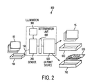
- FIG. 2 illustrates a system for printing an image to a reusable image forming medium containing the signature material.
- the present disclosure provides a printing media, method, and printer system for printing images without using ink or toner and separating reusable printing media from incompatible paper media.
- the reusable printing media has a special imagable composition and it is “printed” (that is, an image is formed on the reusable media) without ink or toner, for example by forming the image with the use of UV light, and the reusable media further includes a signature material.
- the reusable media thus allows image formation using a printer that does not require ink or toner replacement, and instead images the paper, for example, by using a UV light source, such as a LED, when the printer detects the signature material.
- any known or future developed re-imageable media may be used.
- an inkless paper or image forming medium 10 formed using a composition that is imagable without ink, such as using UV light.
- the inkless paper or image forming medium 10 is further provided with a signature material 20 for indicating that the inkless paper or image forming medium 10 is compatible with an inkless printer, for example a UV light printer.
- the image forming medium may comprise a supporting substrate, coated or impregnated on at least one side with the imaging layer.
- the substrate can be coated or impregnated on either only one side, or on both sides, with the imaging layer.
- an opaque layer may be included between the supporting substrate and the imaging layer(s) or on the opposite side of the supporting substrate from the coated imaging layer.
- the image forming medium may include a supporting substrate, coated or impregnated on one side with the imaging layer and coated on the other side with an opaque layer such as, for example, a white layer.
- the image forming medium may include a supporting substrate, coated or impregnated on one side with the imaging layer and with an opaque layer between the substrate and the imaging layer. If a two-sided image forming medium is desired, then the image forming medium may include a supporting substrate, coated or impregnated on both sides with the imaging layer, and with at least one opaque layer interposed between the two coated imaging layers.
- an opaque supporting substrate such as conventional paper, may be used in place of a separate supporting substrate and opaque layer, if desired.
- any suitable supporting substrate may be used.
- suitable examples of supporting substrates include: glass, ceramics, wood, plastics, paper, fabrics, textile products, polymeric films, inorganic substrates such as metals, and the like.
- the plastic may be for example a plastic film, such as polyethylene film, polyethylene terephthalate, polyethylene naphthalate, polystyrene, polycarbonate, polyethersulfone.
- the paper may be, for example, plain paper such as XEROX® 4024 paper, ruled notebook paper, bond paper, silica coated papers such as Sharp Company silica coated paper, Jujo paper, and the like.
- the substrate may be a single layer or multi-layer where each layer is the same or different material.
- the substrate may have a thickness ranging for example from about 0.3 mm to about 5 mm, although smaller or greater thicknesses can be used, if desired.
- the image forming medium generally comprises an imaging layer coated on or impregnated in a suitable substrate material, or sandwiched between a first and a second substrate material, and a signature material that is either visible or invisible that is coated on or impregnated into the substrate material.
- the imaging layer can include any suitable material that, when exposed to an activating energy such as ultraviolet light, switches from a first clear state to a second colored state.
- the color state change in embodiments can be reversed, and thus the image “erased” and the image forming medium returned to a blank state, by various means such as heating the composition to a temperature that reverses the image forming reaction, thus returning the material to its clear state.
- the signature material may be any suitable material that can be coated on or impregnated into the substrate material and provide an optical or spectral response.
- the signature material may be visible or invisible to the naked eye.
- the signature material is detectable by a sensor, and thus a device can confirm (by detecting the signature material) that the correct media type is available for inkless printing. In this way, printing errors can be avoided by, rejecting incompatible media, if incompatible media (such as regular paper) was inadvertently loaded into the media feed tray.
- the signature materials may be disposed on the image forming medium so as not to occupy portions of the image forming medium that are to be imaged.
- the signature materials may also be disposed on the image forming medium so as to occupy portions of the image forming medium that are to be imaged.
- the signature material therefore does not necessarily affect the print quality of the image forming medium, and may thus be imaged over without affecting the signature material or the quality of the image.
- the signature material does not occupy portions of the image forming medium that are to be imaged.
- the signature material is typically disposed on the image forming medium on portions of the outside edge of the medium, in the margins of the medium or the corners of the medium.
- the signature material may be disposed in symmetrical or non-symmetrical patterns on the image forming medium.
- the signature may be formed to occupy entire regions of one or more edges of the image forming medium, such as four corners of the image forming medium or four edges of the image forming medium.
- the image forming medium may be imagable on both or all sides of the medium
- the image forming medium preferably has signature material disposed on both or all sides of the image forming medium.
- FIG. 1 illustrates a signature material disposed in each corner of a side of reusable media.
- the size of the signature material on the image forming medium may vary. Various shapes and sizes of signature material markings may be disposed on the image forming medium. For example, a signature material marking may be as small as 1 micron in size or larger. The signature material size may also be as small as 3 millimeters in size or larger. Smaller size signature material markings may require higher fidelity sensors and/or higher powered illumination devices to produce a spectral response capable of being detected.
- Any suitable visible signature material can be used, where the signature material is visible to the human eye under ambient light.
- Various visible signature materials such as colored or black inks, dyes, toners, chromophore functionalized polymers and the like may be used.
- Visible signature materials can be detected by sensors tuned to the particular spectral response of the visible signature material.
- the visible signature material could further contain invisible fluorescent material to be detected by sensors tuned to the spectral response of the invisible fluorescent material.
- the signature material may also be generally referred to as a “green” marking.
- the green marking indicates to an individual that the marked paper is reusable paper and is environmentally friendly or “green”.
- a visible green marking provides the additional benefit of indicating to bystanders that the individual using the reusable paper is environmentally conscious.
- Invisible signature materials may also be used. By invisible, it is intended that the material is substantially not seen by a naked human eye under ambient light conditions.
- the material may be made detectable by a sensor upon exposure to an activating radiation, for example may be made to fluoresce for a detectable period of time, by exposure to UV light, and a sensor can then detect the material or the spectral response of the material.
- Any suitable invisible signature material can also be used in conjunction with, or separately from visible signature materials.
- Various invisible signature materials that may be used include fluorescent dyes, fluorescent pigments, quantum dots, fluorescence functionalized polymers and the like may be used.
- Suitable fluorescent inks are commercially available, for example, the IF2 series from Risk Reactor.
- the IF2 series from Risk Reactor may emit red, green, yellow, blue or any other desired bright color when exposed to UV light. Detection may be accomplished using a long wavelength 300 nanometer Entela UVGL-25 4 Watt UV lamp. Additionally, UV light emitting diodes LEDs in the 350 to 410 nm range are also available from several sources, Nichia for example, and can also be used in this application.
- the signature material may be applied to the image forming medium at the time of manufacturing the medium or after the manufacturing of the medium.
- the signature material may be applied to the image forming medium in using any suitable means for applying a material to a image forming medium.
- Various methods of applying the signature material to an image forming medium include, for example, inkjet printing, flexographic printing, xerographic printing, offset printing, coating methods, adding a special adhesive patch and other printing or coating methods.
- the signature material may be applied to the substrate itself.
- the signature material can be applied over the image forming layer of the substrate.
- the signature material may be any color. It may be desirable that the visible signature material exhibit a green color because green is traditionally associated with environmental friendliness. Thus, the green color could be used to additionally indicate that the reusable paper is environmentally friendly. It may also be desirable that the invisible signature material, such as a invisible fluorescent material, exhibit a green color when exposed to UV or other light sources. Thus, when the invisible signature material fluoresces, an individual would notice that the paper was environmentally friendly, or “green”. In other instances, the signature material may only fluoresce briefly in the device, and the user may never see the fluorescent response.
- the signature material may be selected based on particular optical characteristics that are desired, for example, emission wavelength and frequency.
- the sensors present in the system can be tuned to detect the specific optical characteristics of the signature material.
- different signature materials can be used to mark different types of image forming media. It may thus be appreciated that different particular signature materials be used for different types of image forming media, thus indicating individual image forming medias compatibility with corresponding inkless printing systems.
- the signature material may desirably be a material that is permanent. For example, a material that lasts as long or longer than the life of the image forming media it is disposed on. However, it may be desired in some instances to have a signature material that is non-permanent and dissipates in a time period that is shorter than the life of the image forming medium.
- the present disclosure provides a system for printing an image to a compatible reusable image forming medium 10 ( FIG. 1 only), the system comprising:
- media 50 in tray 100 may be compatible reusable media 10 or other media that should not be fed to the device 800 , lest it cause print malfunctions;
- a transport path 150 that transports the media from tray 100 towards device 800 ;
- a sensor 200 located in transport path 150 and before device 800 that senses whether a signature material 20 is present on the fed media 50 and outputs a signal;
- a deciding unit 400 that decides, based on the signal output from the sensor 200 , whether the fed media 50 is compatible reusable media 10 or incompatible media 15 ,
- the compatible reusable media 10 is fed along path 150 to exposure source 500 for imaging, and imaged compatible media 900 is output to tray 700 , and
- the incompatible media 15 is transported to bypass exposure source 500 and is output to tray 600 without being imaged. (See FIG. 2 )
- the media 50 may be fed through the device past the imaging source 500 , but not subjected to printing, and thus simply pass to the output tray.
- a message indicating a fault or error may be provided to the user so the user understands the reason for the non-printing.
- the printer may then print on the next compatible reusable media sheet that is detected.
- the sensor 200 can be any known optical sensor capable of detecting a spectral response of a signature material 20 .
- Suitable optical sensors include photoelectric cells, filtered silicon photodetectors, charge coupled device (CCD) line or area scan detectors or color CCD cameras.
- the sensor 200 thus attempts to detect the signature material 20 as the media 50 passes by the sensor. If the sensor 200 detects the signature material 20 , the sensor outputs a signal, to the deciding unit 400 , that the media 50 passing through the inkless printer device 800 is indeed compatible with the inkless printer.
- the media having the signature material thereon is considered compatible reusable media 10 for use with the inkless printing system.
- the printer will then proceed to print an image on the image forming medium 10 using an inkless printing method, such as the application of UV light to the image forming medium using a UV light print source 500 .
- the imaged compatible media 900 is sent to an output tray 700 that is designated for imaged compatible media 900 .
- the determining unit indicates that the media is considered to be incompatible media 15 for the inkless printing system 800 .
- the system in this instance, will not attempt to print an image on the incompatible media 15 .
- the incompatible media then bypasses exposure unit 500 and sent to an output tray 600 designated to be for incompatible media 15 .
- the incompatible media 15 is separated from the imaged compatible media 900 . In this regard, print jams and print failures normally caused by incompatible media are avoided.
- a further overcoating layer may also be applied over the applied imaging layer and/or the signature material.
- the further overcoating layer may, for example, be applied to further adhere the underlying layer in place over the substrate, to provide wear resistance, to improve appearance and feel, and the like.
- the overcoating layer can be the same as or different from the substrate material.
- at least one of the overcoating layer and substrate layer is clear and transparent to permit visualization of the formed image.
- the coating can be conducted by any suitable method available in the art, and the coating method is not particularly limited.
- the imaging material can be coated on or impregnated into the substrate by dip coating the substrate into a solution of the imaging material composition followed by any necessary drying, or the substrate can be coated with the imaging composition to form a layer thereof.
- the protective coating can be applied by similar methods.
- the present disclosure involves producing an image on a reusable image forming medium, the method comprising:
- the exposure source used to form the transient image may also be used to illuminate the signature material.
- UV LEDs may be used to illuminate an invisible fluorescent signature material. After illumination by the UV light source the invisible fluorescent material will fluoresce and provide a specific spectral response that is detectable by the sensor in the printing system.
- the image forming media having a signature material could be used in conjunction with a dual-use printer.
- a dual-use printer such as a printer having both a UV printhead and an inkjet printhead could be used.
- the feed tray corresponding to the dual-use printer could contain a mixture of media, including reusable media and regular paper.
- the dual-use printer could be used to detect whether a signature material is present, as on compatible reusable media, or whether no signature material is present as on regular paper. Based on the presence of the signature material, a deciding unit could determine which transport path the media should follow.
- One media path of the dual-use printer would transport the media to a inkless printhead if the signature material is detected, and if the sensor does not detect the signature material the media would be sent along an alternate transport path so as to be fed to an inkjet printhead.
Abstract
Description
-
- wherein the image is printed on the image forming medium if the signature material is detected.
-
- wherein the image is produced on the media by an inkless printer if the signature material is detected on the fed media, and
- wherein if the signature material is not detected, indicating that the image forming medium is not compatible, an image is not produced on the media by an inkless printer.
Claims (13)
Priority Applications (1)
| Application Number | Priority Date | Filing Date | Title |
|---|---|---|---|
| US13/042,944 US8360541B2 (en) | 2009-03-09 | 2011-03-08 | Reusable paper media with compatibility markings and printer with incompatible media sensor |
Applications Claiming Priority (2)
| Application Number | Priority Date | Filing Date | Title |
|---|---|---|---|
| US12/400,147 US7935463B2 (en) | 2009-03-09 | 2009-03-09 | Reusable paper media with compatibility markings and printer with incompatible media sensor |
| US13/042,944 US8360541B2 (en) | 2009-03-09 | 2011-03-08 | Reusable paper media with compatibility markings and printer with incompatible media sensor |
Related Parent Applications (1)
| Application Number | Title | Priority Date | Filing Date |
|---|---|---|---|
| US12/400,147 Division US7935463B2 (en) | 2009-03-09 | 2009-03-09 | Reusable paper media with compatibility markings and printer with incompatible media sensor |
Publications (2)
| Publication Number | Publication Date |
|---|---|
| US20110157267A1 US20110157267A1 (en) | 2011-06-30 |
| US8360541B2 true US8360541B2 (en) | 2013-01-29 |
Family
ID=42299233
Family Applications (2)
| Application Number | Title | Priority Date | Filing Date |
|---|---|---|---|
| US12/400,147 Active 2029-05-28 US7935463B2 (en) | 2009-03-09 | 2009-03-09 | Reusable paper media with compatibility markings and printer with incompatible media sensor |
| US13/042,944 Active US8360541B2 (en) | 2009-03-09 | 2011-03-08 | Reusable paper media with compatibility markings and printer with incompatible media sensor |
Family Applications Before (1)
| Application Number | Title | Priority Date | Filing Date |
|---|---|---|---|
| US12/400,147 Active 2029-05-28 US7935463B2 (en) | 2009-03-09 | 2009-03-09 | Reusable paper media with compatibility markings and printer with incompatible media sensor |
Country Status (6)
| Country | Link |
|---|---|
| US (2) | US7935463B2 (en) |
| EP (1) | EP2228229B1 (en) |
| JP (1) | JP2010208324A (en) |
| KR (1) | KR20100101534A (en) |
| CN (1) | CN101833252B (en) |
| CA (1) | CA2695136C (en) |
Cited By (1)
| Publication number | Priority date | Publication date | Assignee | Title |
|---|---|---|---|---|
| US20150273894A1 (en) * | 2014-03-31 | 2015-10-01 | Seiko Epson Corporation | Printing device |
Families Citing this family (6)
| Publication number | Priority date | Publication date | Assignee | Title |
|---|---|---|---|---|
| JP5653293B2 (en) * | 2010-06-01 | 2015-01-14 | 株式会社東芝 | Inkjet recording device |
| CN103434270B (en) * | 2013-09-11 | 2015-11-11 | 吉林大学 | A kind of inkless printing equipment |
| CN103774499B (en) * | 2014-02-18 | 2016-02-03 | 齐鲁工业大学 | A kind of fluorescence enetutanedioic acid anhydride sizing emulsions and preparation method thereof |
| CN104070834A (en) * | 2014-06-26 | 2014-10-01 | 余应皇 | Waste paper circulating reusing method and waste paper circulating reusing printer |
| CN106791797A (en) | 2017-03-14 | 2017-05-31 | 京东方科技集团股份有限公司 | The method and apparatus that a kind of double vision shows |
| US11201978B2 (en) * | 2019-01-17 | 2021-12-14 | Validoo Ltd. | System and method for archiving documents |
Citations (21)
| Publication number | Priority date | Publication date | Assignee | Title |
|---|---|---|---|---|
| US5438928A (en) | 1990-01-31 | 1995-08-08 | Thomas De La Rue & Company Limited | Signature panels |
| US6293668B1 (en) | 1998-04-29 | 2001-09-25 | Xerox Corporation | Method and apparatus for treating recording media to enhance print quality in an ink jet printer |
| US6541100B1 (en) | 1998-12-31 | 2003-04-01 | Eastman Kodak Company | Imaged medium comprising sensor-readable indicia |
| CN1475868A (en) | 2002-07-17 | 2004-02-18 | 佳能株式会社 | Image forming system, image transmission apparatus and image forming method |
| US20050244744A1 (en) | 2004-04-29 | 2005-11-03 | Xerox Corporation | Method for forming temporary image |
| US20050244742A1 (en) | 2004-04-29 | 2005-11-03 | Xerox Corporation | Reimageable medium with light absorbing material |
| US20050244743A1 (en) | 2004-04-29 | 2005-11-03 | Xerox Corporation. | Reimageable medium |
| US20060062997A1 (en) * | 2004-09-08 | 2006-03-23 | Kakuji Murakami | Reusable electrophotographic recording medium and method for producing the same, image forming method, and method for repeatedly using electrophotographic recording medium |
| US20060072139A1 (en) | 2004-09-30 | 2006-04-06 | Xerox Corporation | Media size sense system and firmware algorithm for an image formation device |
| US20070119951A1 (en) | 2005-11-30 | 2007-05-31 | Auslander Judith D | Combined multi-spectral document markings |
| US20070140775A1 (en) | 2005-12-21 | 2007-06-21 | Palo Alto Research Center Incorporated | Portable marking device for use with transient document media |
| US7256921B2 (en) | 2003-07-01 | 2007-08-14 | Transitions Optical, Inc. | Polarizing, photochromic devices and methods of making the same |
| US20080110995A1 (en) | 2006-10-31 | 2008-05-15 | Xerox Corporation | Method for embedding machine-readable information with fluorescent materials |
| US20080191136A1 (en) | 2007-02-13 | 2008-08-14 | Palo Alto Research Center Incorporated And Xerox Corporation | Method and system for forming temporary images |
| US20080310869A1 (en) | 2007-06-13 | 2008-12-18 | Xerox Corporation | System and method for printing reimageable transient documents |
| US20090097898A1 (en) | 2007-10-16 | 2009-04-16 | Xerox Corporation | Hand held photochromic marking implement |
| US7645560B1 (en) | 2008-09-08 | 2010-01-12 | Xerox Corporation | Inkless reimageable printing paper and method |
| US20100225722A1 (en) * | 2009-03-09 | 2010-09-09 | Xerox Corporation | Combined inkjet and photochromic reusable paper personal printer |
| US20100227760A1 (en) | 2009-03-09 | 2010-09-09 | Xerox Corporation | Reimageable and reusable medium and method of producing and using the reimageable and reusable medium |
| US20110226851A1 (en) * | 1999-05-25 | 2011-09-22 | Silverbrook Research Pty Ltd | Method of interacting with substrate in cursor and hyperlinking modes |
| US20120048142A1 (en) * | 2006-09-26 | 2012-03-01 | Hiroto Sugahara | Printing apparatus, program, storage medium, method, and ink |
Family Cites Families (10)
| Publication number | Priority date | Publication date | Assignee | Title |
|---|---|---|---|---|
| US5499093A (en) * | 1993-06-18 | 1996-03-12 | Xeikon Nv | Electrostatographic single-pass multiple station printer with register control |
| JPH11282326A (en) * | 1998-03-26 | 1999-10-15 | Canon Inc | Process cartridge, and electrophotographic image forming device |
| JP2000190640A (en) * | 1998-12-28 | 2000-07-11 | Ricoh Co Ltd | Reversible recording medium having identification information |
| JP2002321397A (en) * | 2001-04-26 | 2002-11-05 | Ricoh Co Ltd | Image forming device |
| JP2004268411A (en) * | 2003-03-07 | 2004-09-30 | Matsushita Electric Ind Co Ltd | Information processing system and information processing method |
| US7452847B2 (en) * | 2004-11-02 | 2008-11-18 | Ricoh Company, Ltd. | Reversible thermosensitive recording medium, reversible thermosensitive recording label, reversible thermosensitive recording device, image processing apparatus, and image processing method |
| US8367580B2 (en) * | 2006-03-07 | 2013-02-05 | Ncr Corporation | Dual-sided thermal security features |
| US7777770B2 (en) * | 2005-12-08 | 2010-08-17 | Ncr Corporation | Dual-sided two-ply direct thermal image element |
| WO2007119951A1 (en) * | 2006-04-17 | 2007-10-25 | Moon Key Lee | Sighting device using virtual camera |
| US7572560B2 (en) * | 2007-06-13 | 2009-08-11 | Xerox Corporation | Inkless reimageable printing paper and method |
-
2009
- 2009-03-09 US US12/400,147 patent/US7935463B2/en active Active
-
2010
- 2010-02-24 EP EP10154501A patent/EP2228229B1/en not_active Not-in-force
- 2010-03-02 CA CA2695136A patent/CA2695136C/en not_active Expired - Fee Related
- 2010-03-02 JP JP2010045368A patent/JP2010208324A/en active Pending
- 2010-03-08 KR KR1020100020347A patent/KR20100101534A/en not_active Application Discontinuation
- 2010-03-08 CN CN2010101280957A patent/CN101833252B/en not_active Expired - Fee Related
-
2011
- 2011-03-08 US US13/042,944 patent/US8360541B2/en active Active
Patent Citations (23)
| Publication number | Priority date | Publication date | Assignee | Title |
|---|---|---|---|---|
| US5438928A (en) | 1990-01-31 | 1995-08-08 | Thomas De La Rue & Company Limited | Signature panels |
| US6293668B1 (en) | 1998-04-29 | 2001-09-25 | Xerox Corporation | Method and apparatus for treating recording media to enhance print quality in an ink jet printer |
| US6541100B1 (en) | 1998-12-31 | 2003-04-01 | Eastman Kodak Company | Imaged medium comprising sensor-readable indicia |
| US20110226851A1 (en) * | 1999-05-25 | 2011-09-22 | Silverbrook Research Pty Ltd | Method of interacting with substrate in cursor and hyperlinking modes |
| CN1475868A (en) | 2002-07-17 | 2004-02-18 | 佳能株式会社 | Image forming system, image transmission apparatus and image forming method |
| US20040066535A1 (en) | 2002-07-17 | 2004-04-08 | Masashi Oyumi | Image forming system, image distribution apparatus, and image forming method |
| US7256921B2 (en) | 2003-07-01 | 2007-08-14 | Transitions Optical, Inc. | Polarizing, photochromic devices and methods of making the same |
| US20050244742A1 (en) | 2004-04-29 | 2005-11-03 | Xerox Corporation | Reimageable medium with light absorbing material |
| US20050244743A1 (en) | 2004-04-29 | 2005-11-03 | Xerox Corporation. | Reimageable medium |
| US7300727B2 (en) | 2004-04-29 | 2007-11-27 | Xerox Corporation | Method for forming temporary image |
| US20050244744A1 (en) | 2004-04-29 | 2005-11-03 | Xerox Corporation | Method for forming temporary image |
| US20060062997A1 (en) * | 2004-09-08 | 2006-03-23 | Kakuji Murakami | Reusable electrophotographic recording medium and method for producing the same, image forming method, and method for repeatedly using electrophotographic recording medium |
| US20060072139A1 (en) | 2004-09-30 | 2006-04-06 | Xerox Corporation | Media size sense system and firmware algorithm for an image formation device |
| US20070119951A1 (en) | 2005-11-30 | 2007-05-31 | Auslander Judith D | Combined multi-spectral document markings |
| US20070140775A1 (en) | 2005-12-21 | 2007-06-21 | Palo Alto Research Center Incorporated | Portable marking device for use with transient document media |
| US20120048142A1 (en) * | 2006-09-26 | 2012-03-01 | Hiroto Sugahara | Printing apparatus, program, storage medium, method, and ink |
| US20080110995A1 (en) | 2006-10-31 | 2008-05-15 | Xerox Corporation | Method for embedding machine-readable information with fluorescent materials |
| US20080191136A1 (en) | 2007-02-13 | 2008-08-14 | Palo Alto Research Center Incorporated And Xerox Corporation | Method and system for forming temporary images |
| US20080310869A1 (en) | 2007-06-13 | 2008-12-18 | Xerox Corporation | System and method for printing reimageable transient documents |
| US20090097898A1 (en) | 2007-10-16 | 2009-04-16 | Xerox Corporation | Hand held photochromic marking implement |
| US7645560B1 (en) | 2008-09-08 | 2010-01-12 | Xerox Corporation | Inkless reimageable printing paper and method |
| US20100225722A1 (en) * | 2009-03-09 | 2010-09-09 | Xerox Corporation | Combined inkjet and photochromic reusable paper personal printer |
| US20100227760A1 (en) | 2009-03-09 | 2010-09-09 | Xerox Corporation | Reimageable and reusable medium and method of producing and using the reimageable and reusable medium |
Non-Patent Citations (3)
| Title |
|---|
| Notice of Allowance in U.S. Appl. No. 12/400,147, mailed Jan. 24, 2011. |
| Sep. 28, 2012 First Office Action issued in Chinese Patent Application No. 201010128095.7 (with English translation). |
| U.S. Appl. No. 12/400,147, mailed Aug. 5, 2010. |
Cited By (2)
| Publication number | Priority date | Publication date | Assignee | Title |
|---|---|---|---|---|
| US20150273894A1 (en) * | 2014-03-31 | 2015-10-01 | Seiko Epson Corporation | Printing device |
| US9399360B2 (en) * | 2014-03-31 | 2016-07-26 | Seiko Epson Corporation | Printing device |
Also Published As
| Publication number | Publication date |
|---|---|
| CA2695136A1 (en) | 2010-09-09 |
| CA2695136C (en) | 2013-05-21 |
| JP2010208324A (en) | 2010-09-24 |
| US20110157267A1 (en) | 2011-06-30 |
| US20100227270A1 (en) | 2010-09-09 |
| EP2228229A2 (en) | 2010-09-15 |
| EP2228229B1 (en) | 2012-09-12 |
| CN101833252B (en) | 2013-09-18 |
| US7935463B2 (en) | 2011-05-03 |
| KR20100101534A (en) | 2010-09-17 |
| CN101833252A (en) | 2010-09-15 |
| EP2228229A3 (en) | 2011-04-06 |
Similar Documents
| Publication | Publication Date | Title |
|---|---|---|
| US8360541B2 (en) | Reusable paper media with compatibility markings and printer with incompatible media sensor | |
| US6386671B1 (en) | Orientation independent indicia for print media | |
| US20060032924A1 (en) | Tape indicia on clear film media | |
| EP1136276B1 (en) | Thermal transfer method and apparatus therefor | |
| US8252717B2 (en) | Dual-sided two-ply direct thermal image element | |
| US8764324B2 (en) | Thermal indicators | |
| US20030002029A1 (en) | Marked, difficult-to-counterfeit documents | |
| JP6305043B2 (en) | Printed matter with identification code | |
| WO2000078556A1 (en) | Security documents with visible and invisible markings | |
| US7992959B2 (en) | Printing system with transient and permanent imaging means | |
| JP2004106535A (en) | Inkjet print system | |
| KR100467048B1 (en) | Color ribbon for the prevention of counterfeiting by photo-transfering, preparing method thereof, and security film using the same | |
| JP7111234B2 (en) | thermal transfer printer | |
| JP2005100003A (en) | Information recording medium | |
| JP2005041231A (en) | Ink ribbon of thermal-transfer printer and its manufacturing method | |
| JP2019089301A (en) | Authenticity determination method and printed matter with identification code | |
| WO2011025681A1 (en) | Identification medium configured for displaying visible and excitable indicia | |
| JP2004195713A (en) | Thermal transfer sheet and thermal transfer recording method | |
| JP2015223817A (en) | Heat-sensitive substrate for printing identification code, and printed matter with identification code using the same | |
| JP2009255362A (en) | Thermal transfer printer | |
| JP2004209685A (en) | Transfer sheet and its manufacturing method | |
| JP2006281643A (en) | Identification mark detecting method, judgement processing method, image forming method, and image forming apparatus |
Legal Events
| Date | Code | Title | Description |
|---|---|---|---|
| FEPP | Fee payment procedure |
Free format text: PAYOR NUMBER ASSIGNED (ORIGINAL EVENT CODE: ASPN); ENTITY STATUS OF PATENT OWNER: LARGE ENTITY |
|
| STCF | Information on status: patent grant |
Free format text: PATENTED CASE |
|
| FPAY | Fee payment |
Year of fee payment: 4 |
|
| MAFP | Maintenance fee payment |
Free format text: PAYMENT OF MAINTENANCE FEE, 8TH YEAR, LARGE ENTITY (ORIGINAL EVENT CODE: M1552); ENTITY STATUS OF PATENT OWNER: LARGE ENTITY Year of fee payment: 8 |
|
| AS | Assignment |
Owner name: XEROX CORPORATION, CONNECTICUT Free format text: ASSIGNMENT OF ASSIGNORS INTEREST;ASSIGNOR:PALO ALTO RESEARCH CENTER INCORPORATED;REEL/FRAME:064038/0001 Effective date: 20230416 |
|
| AS | Assignment |
Owner name: CITIBANK, N.A., AS COLLATERAL AGENT, NEW YORK Free format text: SECURITY INTEREST;ASSIGNOR:XEROX CORPORATION;REEL/FRAME:064760/0389 Effective date: 20230621 |
|
| AS | Assignment |
Owner name: XEROX CORPORATION, CONNECTICUT Free format text: CORRECTIVE ASSIGNMENT TO CORRECT THE REMOVAL OF US PATENTS 9356603, 10026651, 10626048 AND INCLUSION OF US PATENT 7167871 PREVIOUSLY RECORDED ON REEL 064038 FRAME 0001. ASSIGNOR(S) HEREBY CONFIRMS THE ASSIGNMENT;ASSIGNOR:PALO ALTO RESEARCH CENTER INCORPORATED;REEL/FRAME:064161/0001 Effective date: 20230416 |
|
| AS | Assignment |
Owner name: JEFFERIES FINANCE LLC, AS COLLATERAL AGENT, NEW YORK Free format text: SECURITY INTEREST;ASSIGNOR:XEROX CORPORATION;REEL/FRAME:065628/0019 Effective date: 20231117 |
|
| AS | Assignment |
Owner name: CITIBANK, N.A., AS COLLATERAL AGENT, NEW YORK Free format text: SECURITY INTEREST;ASSIGNOR:XEROX CORPORATION;REEL/FRAME:066741/0001 Effective date: 20240206 |