US8350479B1 - Emergency light bulb - Google Patents
Emergency light bulb Download PDFInfo
- Publication number
- US8350479B1 US8350479B1 US12/759,773 US75977310A US8350479B1 US 8350479 B1 US8350479 B1 US 8350479B1 US 75977310 A US75977310 A US 75977310A US 8350479 B1 US8350479 B1 US 8350479B1
- Authority
- US
- United States
- Prior art keywords
- light emitters
- plug
- color
- control unit
- wall
- Prior art date
- Legal status (The legal status is an assumption and is not a legal conclusion. Google has not performed a legal analysis and makes no representation as to the accuracy of the status listed.)
- Expired - Fee Related, expires
Links
Images


Classifications
-
- F—MECHANICAL ENGINEERING; LIGHTING; HEATING; WEAPONS; BLASTING
- F21—LIGHTING
- F21V—FUNCTIONAL FEATURES OR DETAILS OF LIGHTING DEVICES OR SYSTEMS THEREOF; STRUCTURAL COMBINATIONS OF LIGHTING DEVICES WITH OTHER ARTICLES, NOT OTHERWISE PROVIDED FOR
- F21V23/00—Arrangement of electric circuit elements in or on lighting devices
- F21V23/04—Arrangement of electric circuit elements in or on lighting devices the elements being switches
- F21V23/0435—Arrangement of electric circuit elements in or on lighting devices the elements being switches activated by remote control means
-
- F—MECHANICAL ENGINEERING; LIGHTING; HEATING; WEAPONS; BLASTING
- F21—LIGHTING
- F21K—NON-ELECTRIC LIGHT SOURCES USING LUMINESCENCE; LIGHT SOURCES USING ELECTROCHEMILUMINESCENCE; LIGHT SOURCES USING CHARGES OF COMBUSTIBLE MATERIAL; LIGHT SOURCES USING SEMICONDUCTOR DEVICES AS LIGHT-GENERATING ELEMENTS; LIGHT SOURCES NOT OTHERWISE PROVIDED FOR
- F21K9/00—Light sources using semiconductor devices as light-generating elements, e.g. using light-emitting diodes [LED] or lasers
- F21K9/20—Light sources comprising attachment means
- F21K9/23—Retrofit light sources for lighting devices with a single fitting for each light source, e.g. for substitution of incandescent lamps with bayonet or threaded fittings
Definitions
- the disclosure relates to light bulbs and more particularly pertains to a new light bulb for PURPOSE.
- An embodiment of the disclosure meets the needs presented above by generally comprising a housing that has a top wall, a bottom wall and a perimeter wall attached to and extending between the top and bottom walls.
- a plug is attached to and extends upwardly from the top wall.
- a flange is defined between the plug and the perimeter wall.
- the plug includes a male plug that is engageable with a female light socket.
- a plurality of light emitters is mounted to the housing.
- a control unit is electrically connected to the plug and the light emitters.
- a receiver for receiving a wireless signal is electrically coupled to the control unit.
- a transmitter is provided for sending a wireless signal to the receiver to turn on the control unit when the transmitter is actuated.
- FIG. 1 is a perspective view of a emergency light bulb according to an embodiment of the disclosure.
- FIG. 2 is a bottom view of an embodiment of the disclosure.
- FIG. 3 is a side view of an embodiment of the disclosure.
- FIG. 4 is a cross-sectional view of an embodiment of the disclosure taken along the line 4 - 4 .
- FIG. 5 is an in-use view of an embodiment of the disclosure.
- FIG. 6 is a front view of an embodiment of the disclosure.
- FIG. 7 is a schematic block diagram of an embodiment of the disclosure.
- FIGS. 1 through 7 a new light bulb embodying the principles and concepts of an embodiment of the disclosure and generally designated by the reference numeral 10 will be described.
- the emergency light bulb 10 generally comprises a housing that has a top wall 12 , a bottom wall 14 and a perimeter wall 16 attached to and extending between the top and bottom walls.
- the top and bottom walls have a circular shape.
- the diameter of the top wall 12 may be between 1 inch and 5 inches.
- the diameter of the bottom wall 14 may be between 2 inches and 8 inches.
- a plug 20 is attached to the top wall 12 and extends upwardly to be received by a light socket.
- a flange 22 is defined between the plug 20 and the perimeter wall 16 .
- the plug 20 includes a male plug 20 to be received by a female light socket.
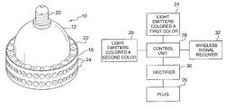
- a plurality of light emitters 24 are mounted to the housing. Some of the light emitters 24 are positioned on the flange 22 and some of the light emitters 24 are positioned on an outer surface of the perimeter wall 16 . Light emitters 24 are also positioned on the bottom wall 14 and adjacent to the perimeter wall 16 . At least some of the light emitters 24 are colored a first color 24 and at least some a second color 26 . The first color 24 and the second color 26 may be contrasting colors so that they are easily distinguishable from each other when flashed alternatively. The light emitters 24 colored the first color 24 are electrically coupled together so that they are capable of being activated at the same time. Likewise, the light emitters 24 colored the second color 26 are electrically coupled together. Each of the light emitters 24 includes a light emitting diode, although one skilled in the art will realize that other types of light emitters 24 may be employed.
- a control unit 28 is electrically connected to the plug 18 and the light emitters 24 for supplying power to the light emitters 24 .
- the control unit 28 includes a rectifier 30 for converting alternating current received from the plug 18 into direct current voltage to the light emitters 24 in an alternating manner so that the light emitters 24 flash between the first color 24 and the second color 26 .
- the control unit 28 may cause the light emitters 24 to flash between red and white, in order to draw the attention of a passerby or emergency service vehicle to the emergency light bulb 10 .
- a receiver 32 for receiving a wireless signal is electrically coupled to the control unit 28 .
- the wireless signal may be infrared or radio-frequency based.
- a transmitter 34 is employed to send a wireless signal to the receiver 32 to turn on the control unit 28 when the transmitter 34 is actuated.
- the transmitter 34 may include a remote control with a power source 36 and a switch 38 to send a wireless signal to turn on the control unit 28 .
- the switch 38 on the transmitter 34 is pushed to send a wireless signal to the receiver 32 , which causes the control unit 28 to flash the light emitters 24 between the first color 24 and the second color 26 .
Abstract
A emergency light bulb for PURPOSE includes a housing that has a top wall, a bottom wall and a perimeter wall attached to and extending between the top and bottom walls. A plug is attached to and extends upwardly from the top wall. A flange is defined between the plug and the perimeter wall. The plug includes a male plug that is engageable with a female light socket. A plurality of light emitters are mounted to the housing. A control unit is electrically connected to the plug and the light emitters. A receiver for receiving a wireless signal is electrically coupled to the control unit. A transmitter is provided for sending a wireless signal to the receiver to turn on the control unit when the transmitter is actuated.
Description
The disclosure relates to light bulbs and more particularly pertains to a new light bulb for PURPOSE.
An embodiment of the disclosure meets the needs presented above by generally comprising a housing that has a top wall, a bottom wall and a perimeter wall attached to and extending between the top and bottom walls. A plug is attached to and extends upwardly from the top wall. A flange is defined between the plug and the perimeter wall. The plug includes a male plug that is engageable with a female light socket. A plurality of light emitters is mounted to the housing. A control unit is electrically connected to the plug and the light emitters. A receiver for receiving a wireless signal is electrically coupled to the control unit. A transmitter is provided for sending a wireless signal to the receiver to turn on the control unit when the transmitter is actuated.
There has thus been outlined, rather broadly, the more important features of the disclosure in order that the detailed description thereof that follows may be better understood, and in order that the present contribution to the art may be better appreciated. There are additional features of the disclosure that will be described hereinafter and which will form the subject matter of the claims appended hereto.
The objects of the disclosure, along with the various features of novelty which characterize the disclosure, are pointed out with particularity in the claims annexed to and forming a part of this disclosure.
The disclosure will be better understood and objects other than those set forth above will become apparent when consideration is given to the following detailed description thereof. Such description makes reference to the annexed drawings wherein:
With reference now to the drawings, and in particular to FIGS. 1 through 7 thereof, a new light bulb embodying the principles and concepts of an embodiment of the disclosure and generally designated by the reference numeral 10 will be described.
As best illustrated in FIGS. 1 through 7 , the emergency light bulb 10 generally comprises a housing that has a top wall 12, a bottom wall 14 and a perimeter wall 16 attached to and extending between the top and bottom walls. The top and bottom walls have a circular shape. The diameter of the top wall 12 may be between 1 inch and 5 inches. The diameter of the bottom wall 14 may be between 2 inches and 8 inches.
A plug 20 is attached to the top wall 12 and extends upwardly to be received by a light socket. A flange 22 is defined between the plug 20 and the perimeter wall 16. The plug 20 includes a male plug 20 to be received by a female light socket.
A plurality of light emitters 24 are mounted to the housing. Some of the light emitters 24 are positioned on the flange 22 and some of the light emitters 24 are positioned on an outer surface of the perimeter wall 16. Light emitters 24 are also positioned on the bottom wall 14 and adjacent to the perimeter wall 16. At least some of the light emitters 24 are colored a first color 24 and at least some a second color 26. The first color 24 and the second color 26 may be contrasting colors so that they are easily distinguishable from each other when flashed alternatively. The light emitters 24 colored the first color 24 are electrically coupled together so that they are capable of being activated at the same time. Likewise, the light emitters 24 colored the second color 26 are electrically coupled together. Each of the light emitters 24 includes a light emitting diode, although one skilled in the art will realize that other types of light emitters 24 may be employed.
A control unit 28 is electrically connected to the plug 18 and the light emitters 24 for supplying power to the light emitters 24. The control unit 28 includes a rectifier 30 for converting alternating current received from the plug 18 into direct current voltage to the light emitters 24 in an alternating manner so that the light emitters 24 flash between the first color 24 and the second color 26. According to an embodiment, the control unit 28 may cause the light emitters 24 to flash between red and white, in order to draw the attention of a passerby or emergency service vehicle to the emergency light bulb 10.
A receiver 32 for receiving a wireless signal is electrically coupled to the control unit 28. The wireless signal may be infrared or radio-frequency based.
A transmitter 34 is employed to send a wireless signal to the receiver 32 to turn on the control unit 28 when the transmitter 34 is actuated. The transmitter 34 may include a remote control with a power source 36 and a switch 38 to send a wireless signal to turn on the control unit 28.
In use in an emergency or other situation in which the attention of passersby may be desired, the switch 38 on the transmitter 34 is pushed to send a wireless signal to the receiver 32, which causes the control unit 28 to flash the light emitters 24 between the first color 24 and the second color 26.
With respect to the above description then, it is to be realized that the optimum dimensional relationships for the parts of an embodiment enabled by the disclosure, to include variations in size, materials, shape, form, function and manner of operation, assembly and use, are deemed readily apparent and obvious to one skilled in the art, and all equivalent relationships to those illustrated in the drawings and described in the specification are intended to be encompassed by an embodiment of the disclosure.
Therefore, the foregoing is considered as illustrative only of the principles of the disclosure. Further, since numerous modifications and changes will readily occur to those skilled in the art, it is not desired to limit the disclosure to the exact construction and operation shown and described, and accordingly, all suitable modifications and equivalents may be resorted to, falling within the scope of the disclosure.
Claims (7)
1. An emergency lighting system comprising:
a light emitting assembly comprising;
a housing having a top wall, a bottom wall and a perimeter wall being attached to and extending between said top and bottom walls;
a plug being attached to and extending upwardly from said top wall, a flange being defined between said plug and said perimeter wall, said plug comprising a male plug being engageable with a female light socket;
a plurality of light emitters being mounted to said housing;
a control unit being electrically connected to said plug and said light emitters, said control unit configured to supply power to said light emitters;
a receiver for receiving a wireless signal being electrically coupled to said control unit; and
a transmitter for sending a wireless signal to said receiver to turn on said control unit when said wherein some of said light emitters are positioned on said flange, wherein some of said light emitters are positioned on an outer surface of said perimeter wall, wherein some of said light emitters are positioned on said bottom wall and being positioned adjacent to said perimeter wall.
2. The emergency lighting system according to claim 1 , wherein said top and bottom walls having a circular shape.
3. The emergency lighting system according to claim 1 , wherein at least some of said light emitters are colored a first color and at least some of said light emitters being colored a second color.
4. The emergency lighting system according to claim 3 , wherein said light emitters colored a first color are electrically coupled together and said light emitters colored a second color are electrically coupled together.
5. The emergency lighting system according to claim 4 , wherein said control unit includes a rectifier for converting alternating current received from said plug into direct current voltage to said light emitters in an alternating manner so that said light emitters flash between the first color and the second color.
6. The emergency lighting system according to claim 1 , wherein each of said light emitters comprises a light emitting diode.
7. An emergency lighting system comprising:
a light emitting assembly comprising;
a housing having a top wall, a bottom wall and a perimeter wall being attached to and extending between said top and bottom walls, said top and bottom walls having a circular shape;
a plug being attached to and extending upwardly from said top wall, a flange being defined between said plug and said perimeter wall, said plug comprising a male plug being engageable with a female light socket;
a plurality of light emitters being mounted to said housing, some of said light emitters being positioned on said flange, some of said light emitters being positioned on an outer surface of said perimeter wall, some of said light emitters being positioned on said bottom wall and being positioned adjacent to said perimeter wall, at least some of said light emitters being colored a first color and at least some of said light emitters being colored a second color, said light emitters colored the first color being electrically coupled together, said light emitters colored the second color being electrically coupled together, each of said light emitters comprising a light emitting diode;
a control unit being electrically connected to said plug and said light emitters, said control unit configured to supply power to said light emitters, said control unit including a rectifier for converting alternating current received from said plug into direct current voltage to said light emitters in an alternating manner so that said light emitters flash between the first color and the second color;
a receiver for receiving a wireless signal being electrically coupled to said control unit; and
a transmitter for sending a wireless signal to said receiver to turn on said control unit when said transmitter is actuated.
Priority Applications (1)
| Application Number | Priority Date | Filing Date | Title |
|---|---|---|---|
| US12/759,773 US8350479B1 (en) | 2010-04-14 | 2010-04-14 | Emergency light bulb |
Applications Claiming Priority (1)
| Application Number | Priority Date | Filing Date | Title |
|---|---|---|---|
| US12/759,773 US8350479B1 (en) | 2010-04-14 | 2010-04-14 | Emergency light bulb |
Publications (1)
| Publication Number | Publication Date |
|---|---|
| US8350479B1 true US8350479B1 (en) | 2013-01-08 |
Family
ID=47427891
Family Applications (1)
| Application Number | Title | Priority Date | Filing Date |
|---|---|---|---|
| US12/759,773 Expired - Fee Related US8350479B1 (en) | 2010-04-14 | 2010-04-14 | Emergency light bulb |
Country Status (1)
| Country | Link |
|---|---|
| US (1) | US8350479B1 (en) |
Cited By (7)
| Publication number | Priority date | Publication date | Assignee | Title |
|---|---|---|---|---|
| US20140098528A1 (en) * | 2012-10-04 | 2014-04-10 | Tadd, LLC | Led retrofit lamp |
| US20140368115A1 (en) * | 2013-06-12 | 2014-12-18 | Panasonic Corporation | Lighting device, method of controlling the same, and lighting system |
| USD755415S1 (en) | 2015-03-03 | 2016-05-03 | Tadd, LLC | LED lamp |
| USD755414S1 (en) | 2015-02-12 | 2016-05-03 | Tadd, LLC | LED lamp |
| JP2018142430A (en) * | 2017-02-27 | 2018-09-13 | パナソニックIpマネジメント株式会社 | Lighting fixture and lighting system |
| US10292243B2 (en) * | 2017-03-01 | 2019-05-14 | Changzhou Jutai Electronic Co., Ltd. | Controller of an LED for receiving a remote control signal |
| US20190360650A1 (en) * | 2018-05-25 | 2019-11-28 | Gary Toner | Lighting unit |
Citations (16)
| Publication number | Priority date | Publication date | Assignee | Title |
|---|---|---|---|---|
| US652509A (en) | 1899-03-07 | 1900-06-26 | Thomas J Cox | Mantel. |
| US4547761A (en) | 1983-12-09 | 1985-10-15 | Jones Richard D | Distress light and signal system |
| US4855723A (en) | 1988-04-29 | 1989-08-08 | Proto Quick, Inc. | Audio-visual alarm system with address display |
| US5270698A (en) | 1990-12-03 | 1993-12-14 | Hoyle Patrick D | Emergency signaling device |
| USD349256S (en) | 1993-06-25 | 1994-08-02 | Bellinger Steven E | Emergency flashing strobe light |
| USD360845S (en) | 1994-07-06 | 1995-08-01 | Public Safety Equipment, Inc. | Emergency warning light base |
| US5489891A (en) * | 1993-01-29 | 1996-02-06 | Noval Controls Sdn Bhd | Control means for lighting devices |
| US5587704A (en) | 1995-09-01 | 1996-12-24 | Foster; Samuel T. | Code blue light audio and visual alarm apparatus |
| USD384589S (en) | 1994-06-20 | 1997-10-07 | Bobby Loach | Quick-alert strobe light for emergency situations |
| US5806965A (en) * | 1996-01-30 | 1998-09-15 | R&M Deese, Inc. | LED beacon light |
| US5880672A (en) | 1996-11-13 | 1999-03-09 | Weaver; Edward | Emergency indicator system |
| US5991363A (en) | 1994-03-21 | 1999-11-23 | Thomson; James D. | Dispatcher-activated response identification light (DARIL) and method for use thereof |
| US7520634B2 (en) * | 1997-12-17 | 2009-04-21 | Philips Solid-State Lighting Solutions, Inc. | Methods and apparatus for controlling a color temperature of lighting conditions |
| US7642730B2 (en) * | 2000-04-24 | 2010-01-05 | Philips Solid-State Lighting Solutions, Inc. | Methods and apparatus for conveying information via color of light |
| US20100056078A1 (en) * | 2008-08-27 | 2010-03-04 | Lowell Phillip Feldman | System and method for providing external power to a device that provides connectivity to a wireless radio frequency access network |
| US8240885B2 (en) * | 2008-11-18 | 2012-08-14 | Abl Ip Holding Llc | Thermal management of LED lighting systems |
-
2010
- 2010-04-14 US US12/759,773 patent/US8350479B1/en not_active Expired - Fee Related
Patent Citations (16)
| Publication number | Priority date | Publication date | Assignee | Title |
|---|---|---|---|---|
| US652509A (en) | 1899-03-07 | 1900-06-26 | Thomas J Cox | Mantel. |
| US4547761A (en) | 1983-12-09 | 1985-10-15 | Jones Richard D | Distress light and signal system |
| US4855723A (en) | 1988-04-29 | 1989-08-08 | Proto Quick, Inc. | Audio-visual alarm system with address display |
| US5270698A (en) | 1990-12-03 | 1993-12-14 | Hoyle Patrick D | Emergency signaling device |
| US5489891A (en) * | 1993-01-29 | 1996-02-06 | Noval Controls Sdn Bhd | Control means for lighting devices |
| USD349256S (en) | 1993-06-25 | 1994-08-02 | Bellinger Steven E | Emergency flashing strobe light |
| US5991363A (en) | 1994-03-21 | 1999-11-23 | Thomson; James D. | Dispatcher-activated response identification light (DARIL) and method for use thereof |
| USD384589S (en) | 1994-06-20 | 1997-10-07 | Bobby Loach | Quick-alert strobe light for emergency situations |
| USD360845S (en) | 1994-07-06 | 1995-08-01 | Public Safety Equipment, Inc. | Emergency warning light base |
| US5587704A (en) | 1995-09-01 | 1996-12-24 | Foster; Samuel T. | Code blue light audio and visual alarm apparatus |
| US5806965A (en) * | 1996-01-30 | 1998-09-15 | R&M Deese, Inc. | LED beacon light |
| US5880672A (en) | 1996-11-13 | 1999-03-09 | Weaver; Edward | Emergency indicator system |
| US7520634B2 (en) * | 1997-12-17 | 2009-04-21 | Philips Solid-State Lighting Solutions, Inc. | Methods and apparatus for controlling a color temperature of lighting conditions |
| US7642730B2 (en) * | 2000-04-24 | 2010-01-05 | Philips Solid-State Lighting Solutions, Inc. | Methods and apparatus for conveying information via color of light |
| US20100056078A1 (en) * | 2008-08-27 | 2010-03-04 | Lowell Phillip Feldman | System and method for providing external power to a device that provides connectivity to a wireless radio frequency access network |
| US8240885B2 (en) * | 2008-11-18 | 2012-08-14 | Abl Ip Holding Llc | Thermal management of LED lighting systems |
Cited By (11)
| Publication number | Priority date | Publication date | Assignee | Title |
|---|---|---|---|---|
| US20140098528A1 (en) * | 2012-10-04 | 2014-04-10 | Tadd, LLC | Led retrofit lamp |
| US20140368115A1 (en) * | 2013-06-12 | 2014-12-18 | Panasonic Corporation | Lighting device, method of controlling the same, and lighting system |
| US9060394B2 (en) * | 2013-06-12 | 2015-06-16 | Panasonic Intellectual Property Management Co., Ltd. | Lighting device, method of controlling the same, and lighting system |
| USD755414S1 (en) | 2015-02-12 | 2016-05-03 | Tadd, LLC | LED lamp |
| USD755415S1 (en) | 2015-03-03 | 2016-05-03 | Tadd, LLC | LED lamp |
| JP2018142430A (en) * | 2017-02-27 | 2018-09-13 | パナソニックIpマネジメント株式会社 | Lighting fixture and lighting system |
| US10236976B2 (en) * | 2017-02-27 | 2019-03-19 | Panasonic Intellectual Property Management Co., Ltd. | Lighting device and lighting system |
| CN113840438A (en) * | 2017-02-27 | 2021-12-24 | 松下知识产权经营株式会社 | Lighting fixture and lighting system |
| CN113840438B (en) * | 2017-02-27 | 2024-02-13 | 松下知识产权经营株式会社 | Lighting fixture and lighting system |
| US10292243B2 (en) * | 2017-03-01 | 2019-05-14 | Changzhou Jutai Electronic Co., Ltd. | Controller of an LED for receiving a remote control signal |
| US20190360650A1 (en) * | 2018-05-25 | 2019-11-28 | Gary Toner | Lighting unit |
Similar Documents
| Publication | Publication Date | Title |
|---|---|---|
| US8350479B1 (en) | Emergency light bulb | |
| US9413104B2 (en) | Magnetic light source adaptor and light source therefor | |
| CN109691229B (en) | Lighting device powered from primary and secondary power sources | |
| US20180231234A1 (en) | Multi-functional head lamps | |
| US9310060B2 (en) | Luminaire with sensing and communication capabilities | |
| US20120126699A1 (en) | LED Light Bulb with Battery Backup and Remote Operation | |
| US20120306384A1 (en) | Illumination device and illumination system | |
| KR101711395B1 (en) | Multi purposes lantern for disaster safe | |
| KR200461298Y1 (en) | Street sign light | |
| CN204879490U (en) | Portable LED projecting lamp | |
| TWM531552U (en) | Multifunctional sensor lamp | |
| KR100615079B1 (en) | Multi-functional traffic signal stick | |
| JP3218820U (en) | Internal illumination traffic cone warning structure | |
| KR20120009306A (en) | A Lihgting Unit of Hole-Cup for Golf Game and Lighting Control Method Using a Sun Electric Cell | |
| CN104358217A (en) | LED traffic warning device | |
| CN101000991A (en) | Socket with luminous device | |
| CN104676430A (en) | Solar LED lamp and solar LED lamp module used for same | |
| CN202091797U (en) | Multifunctional flashlight | |
| CN204879852U (en) | Bicycle color lamp | |
| US8545043B2 (en) | Illumination device for providing synchronous forward and backward lighting | |
| JP3179912U (en) | Lighting device | |
| KR101218006B1 (en) | Led bulb light | |
| CN209944189U (en) | Induction equipment capable of controlling multiple projection lamps | |
| US7646483B2 (en) | Light emitting means with an integrated measuring module and measuring composition module for light emitting means | |
| US20150312993A1 (en) | Illuminant device and controlling module thereof |
Legal Events
| Date | Code | Title | Description |
|---|---|---|---|
| STCF | Information on status: patent grant |
Free format text: PATENTED CASE |
|
| REMI | Maintenance fee reminder mailed | ||
| FPAY | Fee payment |
Year of fee payment: 4 |
|
| SULP | Surcharge for late payment | ||
| FEPP | Fee payment procedure |
Free format text: MAINTENANCE FEE REMINDER MAILED (ORIGINAL EVENT CODE: REM.); ENTITY STATUS OF PATENT OWNER: SMALL ENTITY |
|
| LAPS | Lapse for failure to pay maintenance fees |
Free format text: PATENT EXPIRED FOR FAILURE TO PAY MAINTENANCE FEES (ORIGINAL EVENT CODE: EXP.); ENTITY STATUS OF PATENT OWNER: SMALL ENTITY |
|
| STCH | Information on status: patent discontinuation |
Free format text: PATENT EXPIRED DUE TO NONPAYMENT OF MAINTENANCE FEES UNDER 37 CFR 1.362 |
|
| FP | Lapsed due to failure to pay maintenance fee |
Effective date: 20210108 |