US8335566B2 - Safety system for electrostimulation device - Google Patents
Safety system for electrostimulation device Download PDFInfo
- Publication number
- US8335566B2 US8335566B2 US10/585,796 US58579605A US8335566B2 US 8335566 B2 US8335566 B2 US 8335566B2 US 58579605 A US58579605 A US 58579605A US 8335566 B2 US8335566 B2 US 8335566B2
- Authority
- US
- United States
- Prior art keywords
- plug
- elongate member
- stimulation
- housing
- charger
- Prior art date
- Legal status (The legal status is an assumption and is not a legal conclusion. Google has not performed a legal analysis and makes no representation as to the accuracy of the status listed.)
- Active, expires
Links
Images


Classifications
-
- A—HUMAN NECESSITIES
- A61—MEDICAL OR VETERINARY SCIENCE; HYGIENE
- A61N—ELECTROTHERAPY; MAGNETOTHERAPY; RADIATION THERAPY; ULTRASOUND THERAPY
- A61N1/00—Electrotherapy; Circuits therefor
- A61N1/18—Applying electric currents by contact electrodes
- A61N1/32—Applying electric currents by contact electrodes alternating or intermittent currents
- A61N1/36—Applying electric currents by contact electrodes alternating or intermittent currents for stimulation
- A61N1/372—Arrangements in connection with the implantation of stimulators
- A61N1/375—Constructional arrangements, e.g. casings
- A61N1/3752—Details of casing-lead connections
-
- H—ELECTRICITY
- H01—ELECTRIC ELEMENTS
- H01R—ELECTRICALLY-CONDUCTIVE CONNECTIONS; STRUCTURAL ASSOCIATIONS OF A PLURALITY OF MUTUALLY-INSULATED ELECTRICAL CONNECTING ELEMENTS; COUPLING DEVICES; CURRENT COLLECTORS
- H01R13/00—Details of coupling devices of the kinds covered by groups H01R12/70 or H01R24/00 - H01R33/00
- H01R13/44—Means for preventing access to live contacts
- H01R13/447—Shutter or cover plate
- H01R13/453—Shutter or cover plate opened by engagement of counterpart
- H01R13/4534—Laterally sliding shutter
-
- H—ELECTRICITY
- H05—ELECTRIC TECHNIQUES NOT OTHERWISE PROVIDED FOR
- H05K—PRINTED CIRCUITS; CASINGS OR CONSTRUCTIONAL DETAILS OF ELECTRIC APPARATUS; MANUFACTURE OF ASSEMBLAGES OF ELECTRICAL COMPONENTS
- H05K5/00—Casings, cabinets or drawers for electric apparatus
- H05K5/02—Details
- H05K5/0208—Interlock mechanisms; Means for avoiding unauthorised use or function, e.g. tamperproof
-
- A—HUMAN NECESSITIES
- A61—MEDICAL OR VETERINARY SCIENCE; HYGIENE
- A61N—ELECTROTHERAPY; MAGNETOTHERAPY; RADIATION THERAPY; ULTRASOUND THERAPY
- A61N1/00—Electrotherapy; Circuits therefor
- A61N1/18—Applying electric currents by contact electrodes
- A61N1/32—Applying electric currents by contact electrodes alternating or intermittent currents
- A61N1/36—Applying electric currents by contact electrodes alternating or intermittent currents for stimulation
- A61N1/36003—Applying electric currents by contact electrodes alternating or intermittent currents for stimulation of motor muscles, e.g. for walking assistance
Definitions
- the present invention relates to the field of electrostimulation devices, in particular muscular electrostimulation devices.
- electrostimulation devices that comprise a housing provided with at least one charger plug and one stimulation plug.
- a housing for an electrostimulation device comprises a charger plug and a number of stimulation plugs designed to respectively receive a connector linked to an external charger and a number of connectors linked to stimulation electrodes.
- the housing comprises an accumulator battery that is chargeable by direct current via the charger plug.
- the electrostimulation is produced by means of electrodes applied to the skin of the user.
- the stimulation current is limited to a few tens of milliamps (normally 120 mA maximum for a pulsed current).
- a major risk is run by the user when the housing is linked both to the mains through the charger and to the user through the electrodes.
- the housing is linked both to the mains through the charger and to the user through the electrodes.
- the user could be directly linked to the mains voltage, which represents a mortal hazard.
- a link with the mains can provoke a cardiac fibrillation, a fainting fit, burns, pains, etc.
- the housing disclosed in U.S. Pat. No. 4,421,001 offers a solution to this problem. It comprises a single plug that can operate alternately as a charger plug or a stimulation plug.
- One objective of the invention is to increase the safety of the electrostimulation devices.
- Another objective is to also offer a high level of safety for housings that include a number of stimulation plugs.
- a housing for an electrostimulation device that comprises a charger plug and a stimulation plug, designed to receive respectively a connector linked to a charger and a connector linked to stimulation electrodes.
- the housing according to the invention is characterized in that it also comprises a mobile locking element designed to alternately lock the charger plug or the stimulation plug.
- Particularly advantageous embodiments include a housing for an electrostimulation device that has a charger plug and a stimulation plug.
- the housing includes a mobile locking element that is designed to alternately lock the charger plug or stimulation plug.
- the mobile locking element presents an inclined surface inside the charger plug. Insertion of a connector into the charger plug exerts a force to displace the mobile locking element to lock the stimulation plug.
- the mobile locking element presents an inclined surface inside the stimulation plug. Insertion of a connector into the charger plug exerts a force to displace the mobile locking element to lock the charger plug.
- the charger plug and the stimulation plug are located on two opposite sides of the housing.
- the mobile locking element follows a curvilinear path.
- the mobile locking element may include a thrust element which be activated by a user to release a plug.
- Moving the mobile element from one position to the other can be done either manually, for example using a thrust element that the user moves, or as a consequence of inserting a connector into the plug that is blocked.
- the locking element comprises an inclined surface that is made apparent in the plug. When the connector is inserted into the plug, a force is exerted on the inclined surface, which causes the locking element to be displaced.
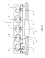
- FIG. 1 presents a first embodiment of the invention with stimulation plugs available.
- FIG. 2 presents the housing of FIG. 1 with a charger plug available.
- FIG. 3 diagrammatically presents a locking principle according to the invention with stimulation plugs available.
- FIG. 4 presents the object of FIG. 3 with a charger plug available.
- FIG. 5 presents a second embodiment of the invention.
- FIG. 6 presents a third embodiment of the invention with a stimulation plug available.
- FIG. 7 presents the object of FIG. 6 with a charger plug available.
- FIG. 8 presents a third embodiment of the invention with stimulation plugs available.
- FIG. 9 presents the object of FIG. 8 with a charger plug available.
- FIG. 10 presents a fourth embodiment of the invention with stimulation plugs available.
- FIG. 11 presents the object of FIG. 10 with a charger plug available.
- FIGS. 1-11 illustrated are a housing 1 , a charger plug 2 , a stimulation plug 3 , a mobile locking element 4 , a locking element of the charger plug 5 , a locking element of the stimulation plug 6 , a thrust element 7 , and an inclined surface 8 .
- the housing 1 represented in FIGS. 1 and 2 comprises a charger plug 2 and four stimulation plugs (each indicated by reference numeral 3 ).
- FIGS. 3 and 4 diagrammatically represent in particular the design illustrated in FIGS. 1 and 2 .
- the housing comprises two mobile locking elements 4 a and 4 b in strip form, which can be displaced in a direction parallel to the line passing through the plugs 2 , 3 .
- Each of strips 4 a and 4 b comprises a series of teeth 6 designed to lock the stimulation plugs 3 .
- the end of each strip 4 a and 4 b which culminates in the charger plug 2 comprises an inclined surface 8 . When the charger connector is inserted into the corresponding plug 2 , a force is exerted on the inclined surface 8 , which drives the strips towards the stimulation plugs 3 , simultaneously locking their access.
- springs are associated with the locking strips 4 a and 4 b . They are located so as to return the locking strips 4 a and 4 b when all the connectors are removed from the housing 1 .
- the locking elements 6 can take the form of teeth, as indicated previously.
- the locking strip 4 can include orifices (not shown) through which the plugs can pass.
- the locking elements are formed by the strip elements that are located between the orifices.
- FIG. 5 The embodiment diagrammatically illustrated in FIG. 5 comprises a locking rod 4 which pivots about its main axis.
- the locking elements 6 are angularly separated by 90° so that the charger 2 and stimulation plugs 3 are alternately locked.
- FIG. 6 also presents a locking rod 4 that pivots, but in a direction perpendicular to the main axis of the rod.
- the charger plug 2 is located on a side of the housing 1 opposite to that where the stimulation plugs 3 are located.
- the mobile locking element 4 is formed by a semi-rigid tab, which is moved in response to the force exerted on the inclined surface 8 by the charger connector.
- FIGS. 10 and 11 presents a mobile locking element 4 that is mobile in a vertical direction.
- a spring (not shown) holds the mobile element 4 in a bottom position (rest position).
- the upward movement of the mobile element 4 is obtained manually through the intermediary of a thrust element 7 that the user must push upward.
- the locking element 5 of the charger plug 2 is in the form of an inverted L.
- Four locking elements 6 for stimulation plugs 3 are located along the mobile locking element 4 , perpendicular to the latter.
- the locking element of the charger plug 5 blocks the charger plug 2 .
- the stimulation plugs 3 are available and can accommodate stimulation connectors.
- the thrust element 7 is eliminated.
- the locking element 5 of the charger plug 2 comprises an inclined surface of a form and function identical to that described previously.
Abstract
Description
Claims (12)
Priority Applications (3)
| Application Number | Priority Date | Filing Date | Title |
|---|---|---|---|
| US13/710,842 US8666492B2 (en) | 2004-01-12 | 2012-12-11 | Safety system for electrostimulation device |
| US14/161,338 US9042986B2 (en) | 2004-01-12 | 2014-01-22 | Safety system for electrostimulation device |
| US14/691,507 US9572980B2 (en) | 2004-01-12 | 2015-04-20 | Safety system for electrostimulation device |
Applications Claiming Priority (4)
| Application Number | Priority Date | Filing Date | Title |
|---|---|---|---|
| CH0040/04 | 2004-01-12 | ||
| CH402004 | 2004-01-12 | ||
| CHCH00040/04 | 2004-01-12 | ||
| PCT/IB2005/050048 WO2005068015A1 (en) | 2004-01-12 | 2005-01-05 | Safety system for electrostimulation device |
Related Parent Applications (1)
| Application Number | Title | Priority Date | Filing Date |
|---|---|---|---|
| PCT/IB2005/050048 A-371-Of-International WO2005068015A1 (en) | 2004-01-12 | 2005-01-05 | Safety system for electrostimulation device |
Related Child Applications (1)
| Application Number | Title | Priority Date | Filing Date |
|---|---|---|---|
| US13/710,842 Continuation US8666492B2 (en) | 2004-01-12 | 2012-12-11 | Safety system for electrostimulation device |
Publications (2)
| Publication Number | Publication Date |
|---|---|
| US20090024188A1 US20090024188A1 (en) | 2009-01-22 |
| US8335566B2 true US8335566B2 (en) | 2012-12-18 |
Family
ID=34754184
Family Applications (4)
| Application Number | Title | Priority Date | Filing Date |
|---|---|---|---|
| US10/585,796 Active 2027-07-02 US8335566B2 (en) | 2004-01-12 | 2005-01-05 | Safety system for electrostimulation device |
| US13/710,842 Active US8666492B2 (en) | 2004-01-12 | 2012-12-11 | Safety system for electrostimulation device |
| US14/161,338 Active US9042986B2 (en) | 2004-01-12 | 2014-01-22 | Safety system for electrostimulation device |
| US14/691,507 Active US9572980B2 (en) | 2004-01-12 | 2015-04-20 | Safety system for electrostimulation device |
Family Applications After (3)
| Application Number | Title | Priority Date | Filing Date |
|---|---|---|---|
| US13/710,842 Active US8666492B2 (en) | 2004-01-12 | 2012-12-11 | Safety system for electrostimulation device |
| US14/161,338 Active US9042986B2 (en) | 2004-01-12 | 2014-01-22 | Safety system for electrostimulation device |
| US14/691,507 Active US9572980B2 (en) | 2004-01-12 | 2015-04-20 | Safety system for electrostimulation device |
Country Status (7)
| Country | Link |
|---|---|
| US (4) | US8335566B2 (en) |
| EP (1) | EP1703942B1 (en) |
| JP (1) | JP4695096B2 (en) |
| AT (1) | ATE387239T1 (en) |
| DE (1) | DE602005005013T2 (en) |
| ES (1) | ES2300978T3 (en) |
| WO (1) | WO2005068015A1 (en) |
Cited By (17)
| Publication number | Priority date | Publication date | Assignee | Title |
|---|---|---|---|---|
| US8666492B2 (en) | 2004-01-12 | 2014-03-04 | Compex Medical S.A. | Safety system for electrostimulation device |
| US11108201B2 (en) * | 2019-01-15 | 2021-08-31 | Harbour Star International Ltd. | Modular system, comprising electrical consuming units and an electrical connection unit |
| US11185690B2 (en) | 2016-05-23 | 2021-11-30 | BTL Healthcare Technologies, a.s. | Systems and methods for tissue treatment |
| US11247039B2 (en) | 2016-05-03 | 2022-02-15 | Btl Healthcare Technologies A.S. | Device including RF source of energy and vacuum system |
| US11247063B2 (en) | 2019-04-11 | 2022-02-15 | Btl Healthcare Technologies A.S. | Methods and devices for aesthetic treatment of biological structures by radiofrequency and magnetic energy |
| US11253717B2 (en) | 2015-10-29 | 2022-02-22 | Btl Healthcare Technologies A.S. | Aesthetic method of biological structure treatment by magnetic field |
| US11253718B2 (en) | 2015-07-01 | 2022-02-22 | Btl Healthcare Technologies A.S. | High power time varying magnetic field therapy |
| US11266852B2 (en) | 2016-07-01 | 2022-03-08 | Btl Healthcare Technologies A.S. | Aesthetic method of biological structure treatment by magnetic field |
| US11464993B2 (en) | 2016-05-03 | 2022-10-11 | Btl Healthcare Technologies A.S. | Device including RF source of energy and vacuum system |
| US11464994B2 (en) | 2016-05-10 | 2022-10-11 | Btl Medical Solutions A.S. | Aesthetic method of biological structure treatment by magnetic field |
| US11484727B2 (en) | 2016-07-01 | 2022-11-01 | Btl Medical Solutions A.S. | Aesthetic method of biological structure treatment by magnetic field |
| US11491342B2 (en) | 2015-07-01 | 2022-11-08 | Btl Medical Solutions A.S. | Magnetic stimulation methods and devices for therapeutic treatments |
| US11491329B2 (en) | 2020-05-04 | 2022-11-08 | Btl Healthcare Technologies A.S. | Device and method for unattended treatment of a patient |
| US11534619B2 (en) | 2016-05-10 | 2022-12-27 | Btl Medical Solutions A.S. | Aesthetic method of biological structure treatment by magnetic field |
| US11612758B2 (en) | 2012-07-05 | 2023-03-28 | Btl Medical Solutions A.S. | Device for repetitive nerve stimulation in order to break down fat tissue means of inductive magnetic fields |
| US11633596B2 (en) | 2020-05-04 | 2023-04-25 | Btl Healthcare Technologies A.S. | Device and method for unattended treatment of a patient |
| US11896816B2 (en) | 2021-11-03 | 2024-02-13 | Btl Healthcare Technologies A.S. | Device and method for unattended treatment of a patient |
Families Citing this family (2)
| Publication number | Priority date | Publication date | Assignee | Title |
|---|---|---|---|---|
| US20180057769A1 (en) * | 2015-07-07 | 2018-03-01 | Exxonmobil Research And Engineering Company | Method and composition for preventing or reducing engine knock and pre-ignition in high compression spark ignition engines |
| US10910743B2 (en) * | 2018-11-06 | 2021-02-02 | Lear Corporation | Electrical assembly and method |
Citations (20)
| Publication number | Priority date | Publication date | Assignee | Title |
|---|---|---|---|---|
| FR1503915A (en) | 1966-10-19 | 1967-12-01 | Removable electrical device operating by all or nothing | |
| US3902502A (en) | 1974-09-13 | 1975-09-02 | Saul Liss | Apparatus for temporarily arresting arthritic pain |
| US3942535A (en) * | 1973-09-27 | 1976-03-09 | G. D. Searle & Co. | Rechargeable tissue stimulating system |
| US4431001A (en) | 1980-09-17 | 1984-02-14 | Crafon Medical Ab | Stimulator system |
| US4759368A (en) * | 1986-12-02 | 1988-07-26 | Medical Designs, Inc. | Transcutaneous nerve stimulator |
| US4770328A (en) * | 1982-12-16 | 1988-09-13 | Medtronic, Inc. | Tissue stimulator casing |
| US5314451A (en) * | 1993-01-15 | 1994-05-24 | Medtronic, Inc. | Replaceable battery for implantable medical device |
| US5507662A (en) * | 1993-06-01 | 1996-04-16 | Siemens Elema Ab | Device for affixing an electrode cable to an apparatus |
| US5573551A (en) * | 1993-11-01 | 1996-11-12 | Intermedics, Inc. | Implantable medical device with detachable battery or electronic circuit |
| US5637417A (en) * | 1995-11-07 | 1997-06-10 | Medtronic, Inc. | Quick change battery drawer for external electrical stimulator |
| US5707399A (en) * | 1995-04-18 | 1998-01-13 | Pacesetter Ab | Arrangement for fixing one or more electrode leads in an implantable medical device, such as a heart stimulator |
| US5758414A (en) | 1994-04-28 | 1998-06-02 | Hubbell Incorporated | Method of making universal electrical connector |
| US5766042A (en) * | 1995-12-28 | 1998-06-16 | Medtronic, Inc. | Tool-less locking and sealing assembly for implantable medical device |
| US5807144A (en) * | 1996-01-29 | 1998-09-15 | Pacesetter Ab | Device for affixing a lead connector to an implantable stimulator |
| US5885109A (en) | 1997-10-16 | 1999-03-23 | Lee; Chiu-Shan | Electrical adapters |
| US6070103A (en) * | 1996-11-05 | 2000-05-30 | Intermedics Inc. | Apparatus for making direct electrical connection with an implantable medical device |
| US20020116035A1 (en) * | 2001-02-16 | 2002-08-22 | Russell Klehn | Connector assembly for implantable medical device |
| WO2005025012A1 (en) | 2003-09-04 | 2005-03-17 | Alpha Shantilal Pabari | Electrical socket |
| US7359751B1 (en) * | 2004-05-05 | 2008-04-15 | Advanced Neuromodulation Systems, Inc. | Clinician programmer for use with trial stimulator |
| US8068914B1 (en) * | 2004-05-05 | 2011-11-29 | Advanced Bionics, Llc | Speech processor cases |
Family Cites Families (4)
| Publication number | Priority date | Publication date | Assignee | Title |
|---|---|---|---|---|
| JPS5147278B2 (en) * | 1972-03-30 | 1976-12-14 | ||
| US4421001A (en) | 1981-02-12 | 1983-12-20 | Kimball International, Inc. | Full note generator system for an electronic organ |
| JP4036763B2 (en) * | 2003-01-24 | 2008-01-23 | 三洋電機株式会社 | Electric equipment having a power plug and a power inlet |
| US8335566B2 (en) | 2004-01-12 | 2012-12-18 | Compex Medical S.A. | Safety system for electrostimulation device |
-
2005
- 2005-01-05 US US10/585,796 patent/US8335566B2/en active Active
- 2005-01-05 AT AT05702578T patent/ATE387239T1/en not_active IP Right Cessation
- 2005-01-05 WO PCT/IB2005/050048 patent/WO2005068015A1/en active Application Filing
- 2005-01-05 ES ES05702578T patent/ES2300978T3/en active Active
- 2005-01-05 DE DE602005005013T patent/DE602005005013T2/en active Active
- 2005-01-05 JP JP2006548507A patent/JP4695096B2/en active Active
- 2005-01-05 EP EP05702578A patent/EP1703942B1/en active Active
-
2012
- 2012-12-11 US US13/710,842 patent/US8666492B2/en active Active
-
2014
- 2014-01-22 US US14/161,338 patent/US9042986B2/en active Active
-
2015
- 2015-04-20 US US14/691,507 patent/US9572980B2/en active Active
Patent Citations (20)
| Publication number | Priority date | Publication date | Assignee | Title |
|---|---|---|---|---|
| FR1503915A (en) | 1966-10-19 | 1967-12-01 | Removable electrical device operating by all or nothing | |
| US3942535A (en) * | 1973-09-27 | 1976-03-09 | G. D. Searle & Co. | Rechargeable tissue stimulating system |
| US3902502A (en) | 1974-09-13 | 1975-09-02 | Saul Liss | Apparatus for temporarily arresting arthritic pain |
| US4431001A (en) | 1980-09-17 | 1984-02-14 | Crafon Medical Ab | Stimulator system |
| US4770328A (en) * | 1982-12-16 | 1988-09-13 | Medtronic, Inc. | Tissue stimulator casing |
| US4759368A (en) * | 1986-12-02 | 1988-07-26 | Medical Designs, Inc. | Transcutaneous nerve stimulator |
| US5314451A (en) * | 1993-01-15 | 1994-05-24 | Medtronic, Inc. | Replaceable battery for implantable medical device |
| US5507662A (en) * | 1993-06-01 | 1996-04-16 | Siemens Elema Ab | Device for affixing an electrode cable to an apparatus |
| US5573551A (en) * | 1993-11-01 | 1996-11-12 | Intermedics, Inc. | Implantable medical device with detachable battery or electronic circuit |
| US5758414A (en) | 1994-04-28 | 1998-06-02 | Hubbell Incorporated | Method of making universal electrical connector |
| US5707399A (en) * | 1995-04-18 | 1998-01-13 | Pacesetter Ab | Arrangement for fixing one or more electrode leads in an implantable medical device, such as a heart stimulator |
| US5637417A (en) * | 1995-11-07 | 1997-06-10 | Medtronic, Inc. | Quick change battery drawer for external electrical stimulator |
| US5766042A (en) * | 1995-12-28 | 1998-06-16 | Medtronic, Inc. | Tool-less locking and sealing assembly for implantable medical device |
| US5807144A (en) * | 1996-01-29 | 1998-09-15 | Pacesetter Ab | Device for affixing a lead connector to an implantable stimulator |
| US6070103A (en) * | 1996-11-05 | 2000-05-30 | Intermedics Inc. | Apparatus for making direct electrical connection with an implantable medical device |
| US5885109A (en) | 1997-10-16 | 1999-03-23 | Lee; Chiu-Shan | Electrical adapters |
| US20020116035A1 (en) * | 2001-02-16 | 2002-08-22 | Russell Klehn | Connector assembly for implantable medical device |
| WO2005025012A1 (en) | 2003-09-04 | 2005-03-17 | Alpha Shantilal Pabari | Electrical socket |
| US7359751B1 (en) * | 2004-05-05 | 2008-04-15 | Advanced Neuromodulation Systems, Inc. | Clinician programmer for use with trial stimulator |
| US8068914B1 (en) * | 2004-05-05 | 2011-11-29 | Advanced Bionics, Llc | Speech processor cases |
Cited By (40)
| Publication number | Priority date | Publication date | Assignee | Title |
|---|---|---|---|---|
| US9042986B2 (en) | 2004-01-12 | 2015-05-26 | Djo Global Switzerland Sàrl | Safety system for electrostimulation device |
| US9572980B2 (en) | 2004-01-12 | 2017-02-21 | DJO Global Switzerland Sarl | Safety system for electrostimulation device |
| US8666492B2 (en) | 2004-01-12 | 2014-03-04 | Compex Medical S.A. | Safety system for electrostimulation device |
| US11612758B2 (en) | 2012-07-05 | 2023-03-28 | Btl Medical Solutions A.S. | Device for repetitive nerve stimulation in order to break down fat tissue means of inductive magnetic fields |
| US11253718B2 (en) | 2015-07-01 | 2022-02-22 | Btl Healthcare Technologies A.S. | High power time varying magnetic field therapy |
| US11266850B2 (en) | 2015-07-01 | 2022-03-08 | Btl Healthcare Technologies A.S. | High power time varying magnetic field therapy |
| US11491342B2 (en) | 2015-07-01 | 2022-11-08 | Btl Medical Solutions A.S. | Magnetic stimulation methods and devices for therapeutic treatments |
| US11253717B2 (en) | 2015-10-29 | 2022-02-22 | Btl Healthcare Technologies A.S. | Aesthetic method of biological structure treatment by magnetic field |
| US11464993B2 (en) | 2016-05-03 | 2022-10-11 | Btl Healthcare Technologies A.S. | Device including RF source of energy and vacuum system |
| US11883643B2 (en) | 2016-05-03 | 2024-01-30 | Btl Healthcare Technologies A.S. | Systems and methods for treatment of a patient including RF and electrical energy |
| US11247039B2 (en) | 2016-05-03 | 2022-02-15 | Btl Healthcare Technologies A.S. | Device including RF source of energy and vacuum system |
| US11602629B2 (en) | 2016-05-03 | 2023-03-14 | Btl Healthcare Technologies A.S. | Systems and methods for treatment of a patient including rf and electrical energy |
| US11534619B2 (en) | 2016-05-10 | 2022-12-27 | Btl Medical Solutions A.S. | Aesthetic method of biological structure treatment by magnetic field |
| US11590356B2 (en) | 2016-05-10 | 2023-02-28 | Btl Medical Solutions A.S. | Aesthetic method of biological structure treatment by magnetic field |
| US11691024B2 (en) | 2016-05-10 | 2023-07-04 | Btl Medical Solutions A.S. | Aesthetic method of biological structure treatment by magnetic field |
| US11464994B2 (en) | 2016-05-10 | 2022-10-11 | Btl Medical Solutions A.S. | Aesthetic method of biological structure treatment by magnetic field |
| US11896821B2 (en) | 2016-05-23 | 2024-02-13 | Btl Healthcare Technologies A.S. | Systems and methods for tissue treatment |
| US11878162B2 (en) | 2016-05-23 | 2024-01-23 | Btl Healthcare Technologies A.S. | Systems and methods for tissue treatment |
| US11458307B2 (en) | 2016-05-23 | 2022-10-04 | Btl Healthcare Technologies A.S. | Systems and methods for tissue treatment |
| US11623083B2 (en) | 2016-05-23 | 2023-04-11 | Btl Healthcare Technologies A.S. | Systems and methods for tissue treatment |
| US11185690B2 (en) | 2016-05-23 | 2021-11-30 | BTL Healthcare Technologies, a.s. | Systems and methods for tissue treatment |
| US11524171B2 (en) | 2016-07-01 | 2022-12-13 | Btl Medical Solutions A.S. | Aesthetic method of biological structure treatment by magnetic field |
| US11484727B2 (en) | 2016-07-01 | 2022-11-01 | Btl Medical Solutions A.S. | Aesthetic method of biological structure treatment by magnetic field |
| US11607556B2 (en) | 2016-07-01 | 2023-03-21 | Btl Medical Solutions A.S. | Aesthetic method of biological structure treatment by magnetic field |
| US11266852B2 (en) | 2016-07-01 | 2022-03-08 | Btl Healthcare Technologies A.S. | Aesthetic method of biological structure treatment by magnetic field |
| US11497925B2 (en) | 2016-07-01 | 2022-11-15 | Btl Medical Solutions A.S. | Aesthetic method of biological structure treatment by magnetic field |
| US11628308B2 (en) | 2016-07-01 | 2023-04-18 | Btl Medical Solutions A.S. | Aesthetic method of biological structure treatment by magnetic field |
| US11679270B2 (en) | 2016-07-01 | 2023-06-20 | Btl Medical Solutions A.S. | Aesthetic method of biological structure treatment by magnetic field |
| US11794029B2 (en) | 2016-07-01 | 2023-10-24 | Btl Medical Solutions A.S. | Aesthetic method of biological structure treatment by magnetic field |
| US11108201B2 (en) * | 2019-01-15 | 2021-08-31 | Harbour Star International Ltd. | Modular system, comprising electrical consuming units and an electrical connection unit |
| US11484725B2 (en) | 2019-04-11 | 2022-11-01 | Btl Medical Solutions A.S. | Methods and devices for aesthetic treatment of biological structures by radiofrequency and magnetic energy |
| US11247063B2 (en) | 2019-04-11 | 2022-02-15 | Btl Healthcare Technologies A.S. | Methods and devices for aesthetic treatment of biological structures by radiofrequency and magnetic energy |
| US11491329B2 (en) | 2020-05-04 | 2022-11-08 | Btl Healthcare Technologies A.S. | Device and method for unattended treatment of a patient |
| US11813451B2 (en) | 2020-05-04 | 2023-11-14 | Btl Healthcare Technologies A.S. | Device and method for unattended treatment of a patient |
| US11826565B2 (en) | 2020-05-04 | 2023-11-28 | Btl Healthcare Technologies A.S. | Device and method for unattended treatment of a patient |
| US11878167B2 (en) | 2020-05-04 | 2024-01-23 | Btl Healthcare Technologies A.S. | Device and method for unattended treatment of a patient |
| US11806528B2 (en) | 2020-05-04 | 2023-11-07 | Btl Healthcare Technologies A.S. | Device and method for unattended treatment of a patient |
| US11679255B2 (en) | 2020-05-04 | 2023-06-20 | Btl Healthcare Technologies A.S. | Device and method for unattended treatment of a patient |
| US11633596B2 (en) | 2020-05-04 | 2023-04-25 | Btl Healthcare Technologies A.S. | Device and method for unattended treatment of a patient |
| US11896816B2 (en) | 2021-11-03 | 2024-02-13 | Btl Healthcare Technologies A.S. | Device and method for unattended treatment of a patient |
Also Published As
| Publication number | Publication date |
|---|---|
| US20090024188A1 (en) | 2009-01-22 |
| JP4695096B2 (en) | 2011-06-08 |
| DE602005005013D1 (en) | 2008-04-10 |
| US8666492B2 (en) | 2014-03-04 |
| US20130172971A1 (en) | 2013-07-04 |
| US9572980B2 (en) | 2017-02-21 |
| EP1703942A1 (en) | 2006-09-27 |
| JP2007517569A (en) | 2007-07-05 |
| DE602005005013T2 (en) | 2009-03-26 |
| ES2300978T3 (en) | 2008-06-16 |
| EP1703942B1 (en) | 2008-02-27 |
| US20150224306A1 (en) | 2015-08-13 |
| ATE387239T1 (en) | 2008-03-15 |
| US9042986B2 (en) | 2015-05-26 |
| WO2005068015A1 (en) | 2005-07-28 |
| US20140135881A1 (en) | 2014-05-15 |
Similar Documents
| Publication | Publication Date | Title |
|---|---|---|
| US8666492B2 (en) | Safety system for electrostimulation device | |
| JP2007517569A6 (en) | Safety system for electronic stimulator | |
| US4097113A (en) | Electrical connectors for portable electronic physiological instruments having separable first and second components | |
| DE69936838T2 (en) | POWER CONNECTOR FOR CHILDREN'S VEHICLE | |
| DE3934799C2 (en) | ||
| US20130244462A1 (en) | Power socket and electrical connector assembly | |
| JP2000509883A (en) | Self-locking battery pack with keyboard input for portable defibrillator | |
| JPH09266025A (en) | Power connector for charging capacitor of electric vehicle | |
| US7801605B2 (en) | Disposable defibrillator electrode assembly | |
| KR101758595B1 (en) | Patch connector for skin exercise and skin care | |
| DE112019001379T5 (en) | Connector module and energy storage module | |
| JP5722147B2 (en) | Battery storage device | |
| CN110979050A (en) | Rifle protection device charges | |
| WO2015092927A1 (en) | Portable rechargeable power supply device | |
| DE602005002926T2 (en) | Charging unit for an electronic device with a protected housing of an adapter plug | |
| EP3145580B1 (en) | Cutaneous electrode device and electrostimulation device including said electrode device | |
| CN213816479U (en) | Modular power strip | |
| KR102126012B1 (en) | Concent having length directional power terminal | |
| CN2290122Y (en) | Tripolar electric socket safety device | |
| DE19545238A1 (en) | Transcutaneous nerve stimulation device | |
| EP1406323A3 (en) | Terminal and battery containing said terminal | |
| JP2709703B2 (en) | Rechargeable small electric equipment | |
| DE20020101U1 (en) | Gas generating device | |
| JP2005520542A (en) | Electroporation chamber | |
| US20080088204A1 (en) | Ion Introducer Employing Piezoelectric Bimorph Element |
Legal Events
| Date | Code | Title | Description |
|---|---|---|---|
| AS | Assignment |
Owner name: COMPEX MEDICAL S.A., SWITZERLAND Free format text: ASSIGNMENT OF ASSIGNORS INTEREST;ASSIGNORS:MULLER, PIERRE-YVES;SCHONENBERGER, KLAUS;REEL/FRAME:018065/0032 Effective date: 20060502 |
|
| STCF | Information on status: patent grant |
Free format text: PATENTED CASE |
|
| FEPP | Fee payment procedure |
Free format text: PAYOR NUMBER ASSIGNED (ORIGINAL EVENT CODE: ASPN); ENTITY STATUS OF PATENT OWNER: LARGE ENTITY Free format text: PAYER NUMBER DE-ASSIGNED (ORIGINAL EVENT CODE: RMPN); ENTITY STATUS OF PATENT OWNER: LARGE ENTITY |
|
| FEPP | Fee payment procedure |
Free format text: PAYOR NUMBER ASSIGNED (ORIGINAL EVENT CODE: ASPN); ENTITY STATUS OF PATENT OWNER: LARGE ENTITY Free format text: PAYER NUMBER DE-ASSIGNED (ORIGINAL EVENT CODE: RMPN); ENTITY STATUS OF PATENT OWNER: LARGE ENTITY |
|
| AS | Assignment |
Owner name: COMPEX SARL, FRANCE Free format text: MERGER AND CHANGE OF NAME;ASSIGNORS:COMPEX SWITZERLAND SARL;COMPEX MEDICAL SA;COMPEX SARL;REEL/FRAME:033975/0446 Effective date: 20130101 |
|
| AS | Assignment |
Owner name: DJO GLOBAL SWITZERLAND SARL, FRANCE Free format text: CHANGE OF NAME;ASSIGNOR:COMPEX SARL;REEL/FRAME:035159/0810 Effective date: 20130705 |
|
| FPAY | Fee payment |
Year of fee payment: 4 |
|
| MAFP | Maintenance fee payment |
Free format text: PAYMENT OF MAINTENANCE FEE, 8TH YEAR, LARGE ENTITY (ORIGINAL EVENT CODE: M1552); ENTITY STATUS OF PATENT OWNER: LARGE ENTITY Year of fee payment: 8 |