US8329437B1 - Disposable particle counter cartridge - Google Patents
Disposable particle counter cartridge Download PDFInfo
- Publication number
- US8329437B1 US8329437B1 US12/639,095 US63909509A US8329437B1 US 8329437 B1 US8329437 B1 US 8329437B1 US 63909509 A US63909509 A US 63909509A US 8329437 B1 US8329437 B1 US 8329437B1
- Authority
- US
- United States
- Prior art keywords
- fluid
- cartridge
- interrogation
- sample
- channel
- Prior art date
- Legal status (The legal status is an assumption and is not a legal conclusion. Google has not performed a legal analysis and makes no representation as to the accuracy of the status listed.)
- Active, expires
Links
- 239000002245 particle Substances 0.000 title claims abstract description 72
- 239000012530 fluid Substances 0.000 claims abstract description 209
- 238000012360 testing method Methods 0.000 claims description 38
- 238000000034 method Methods 0.000 claims description 37
- 238000004891 communication Methods 0.000 claims description 36
- 239000011324 bead Substances 0.000 claims description 31
- 210000004369 blood Anatomy 0.000 claims description 25
- 239000008280 blood Substances 0.000 claims description 25
- 239000003153 chemical reaction reagent Substances 0.000 claims description 23
- 238000002156 mixing Methods 0.000 claims description 23
- 210000000265 leukocyte Anatomy 0.000 claims description 21
- 239000000463 material Substances 0.000 claims description 20
- 238000004458 analytical method Methods 0.000 claims description 19
- 238000007872 degassing Methods 0.000 claims description 19
- 239000002699 waste material Substances 0.000 claims description 18
- 230000002209 hydrophobic effect Effects 0.000 claims description 15
- 239000004816 latex Substances 0.000 claims description 12
- 229920000126 latex Polymers 0.000 claims description 12
- 230000008878 coupling Effects 0.000 claims description 10
- 238000010168 coupling process Methods 0.000 claims description 10
- 238000005859 coupling reaction Methods 0.000 claims description 10
- 238000011068 loading method Methods 0.000 claims description 7
- 239000000427 antigen Substances 0.000 claims description 6
- 102000036639 antigens Human genes 0.000 claims description 6
- 108091007433 antigens Proteins 0.000 claims description 6
- 238000009434 installation Methods 0.000 claims description 5
- 230000002829 reductive effect Effects 0.000 claims description 5
- 230000005012 migration Effects 0.000 claims description 3
- 238000013508 migration Methods 0.000 claims description 3
- 238000007405 data analysis Methods 0.000 claims 3
- 230000000638 stimulation Effects 0.000 claims 3
- FGUUSXIOTUKUDN-IBGZPJMESA-N C1(=CC=CC=C1)N1C2=C(NC([C@H](C1)NC=1OC(=NN=1)C1=CC=CC=C1)=O)C=CC=C2 Chemical compound C1(=CC=CC=C1)N1C2=C(NC([C@H](C1)NC=1OC(=NN=1)C1=CC=CC=C1)=O)C=CC=C2 FGUUSXIOTUKUDN-IBGZPJMESA-N 0.000 claims 1
- 239000000523 sample Substances 0.000 description 74
- 238000001514 detection method Methods 0.000 description 34
- 239000012528 membrane Substances 0.000 description 20
- 210000004027 cell Anatomy 0.000 description 15
- 230000004888 barrier function Effects 0.000 description 9
- 239000000203 mixture Substances 0.000 description 9
- 239000000758 substrate Substances 0.000 description 8
- 239000003085 diluting agent Substances 0.000 description 7
- 210000003743 erythrocyte Anatomy 0.000 description 7
- 239000007789 gas Substances 0.000 description 6
- 230000006872 improvement Effects 0.000 description 6
- 238000000576 coating method Methods 0.000 description 5
- 239000012212 insulator Substances 0.000 description 5
- 238000004519 manufacturing process Methods 0.000 description 5
- 239000000243 solution Substances 0.000 description 5
- 239000011573 trace mineral Substances 0.000 description 5
- 235000013619 trace mineral Nutrition 0.000 description 5
- 239000004809 Teflon Substances 0.000 description 4
- 229920006362 Teflon® Polymers 0.000 description 4
- 238000004820 blood count Methods 0.000 description 4
- 238000010276 construction Methods 0.000 description 4
- 239000003989 dielectric material Substances 0.000 description 4
- 239000007788 liquid Substances 0.000 description 4
- 230000008384 membrane barrier Effects 0.000 description 4
- 229920003223 poly(pyromellitimide-1,4-diphenyl ether) Polymers 0.000 description 4
- 238000011144 upstream manufacturing Methods 0.000 description 4
- 238000005406 washing Methods 0.000 description 4
- 229920002799 BoPET Polymers 0.000 description 3
- 239000005041 Mylar™ Substances 0.000 description 3
- 210000000601 blood cell Anatomy 0.000 description 3
- 239000000470 constituent Substances 0.000 description 3
- 238000005553 drilling Methods 0.000 description 3
- 238000005530 etching Methods 0.000 description 3
- 230000002934 lysing effect Effects 0.000 description 3
- 210000001616 monocyte Anatomy 0.000 description 3
- 239000004033 plastic Substances 0.000 description 3
- XLYOFNOQVPJJNP-UHFFFAOYSA-N water Substances O XLYOFNOQVPJJNP-UHFFFAOYSA-N 0.000 description 3
- HTTJABKRGRZYRN-UHFFFAOYSA-N Heparin Chemical compound OC1C(NC(=O)C)C(O)OC(COS(O)(=O)=O)C1OC1C(OS(O)(=O)=O)C(O)C(OC2C(C(OS(O)(=O)=O)C(OC3C(C(O)C(O)C(O3)C(O)=O)OS(O)(=O)=O)C(CO)O2)NS(O)(=O)=O)C(C(O)=O)O1 HTTJABKRGRZYRN-UHFFFAOYSA-N 0.000 description 2
- 101000946889 Homo sapiens Monocyte differentiation antigen CD14 Proteins 0.000 description 2
- 102100035877 Monocyte differentiation antigen CD14 Human genes 0.000 description 2
- FAPWRFPIFSIZLT-UHFFFAOYSA-M Sodium chloride Chemical compound [Na+].[Cl-] FAPWRFPIFSIZLT-UHFFFAOYSA-M 0.000 description 2
- 210000001772 blood platelet Anatomy 0.000 description 2
- 239000000872 buffer Substances 0.000 description 2
- 239000003795 chemical substances by application Substances 0.000 description 2
- 230000035602 clotting Effects 0.000 description 2
- 239000011248 coating agent Substances 0.000 description 2
- 238000007865 diluting Methods 0.000 description 2
- 201000010099 disease Diseases 0.000 description 2
- 208000037265 diseases, disorders, signs and symptoms Diseases 0.000 description 2
- 238000009826 distribution Methods 0.000 description 2
- 230000000694 effects Effects 0.000 description 2
- 238000004070 electrodeposition Methods 0.000 description 2
- 238000005516 engineering process Methods 0.000 description 2
- 238000011156 evaluation Methods 0.000 description 2
- 238000011049 filling Methods 0.000 description 2
- 239000010408 film Substances 0.000 description 2
- 229960002897 heparin Drugs 0.000 description 2
- 229920000669 heparin Polymers 0.000 description 2
- 238000011534 incubation Methods 0.000 description 2
- 239000003112 inhibitor Substances 0.000 description 2
- 238000005259 measurement Methods 0.000 description 2
- 229910052751 metal Inorganic materials 0.000 description 2
- 239000002184 metal Substances 0.000 description 2
- 238000005459 micromachining Methods 0.000 description 2
- 210000004080 milk Anatomy 0.000 description 2
- 239000008267 milk Substances 0.000 description 2
- 235000013336 milk Nutrition 0.000 description 2
- 238000012544 monitoring process Methods 0.000 description 2
- 239000013618 particulate matter Substances 0.000 description 2
- 229920002120 photoresistant polymer Polymers 0.000 description 2
- BASFCYQUMIYNBI-UHFFFAOYSA-N platinum Chemical compound [Pt] BASFCYQUMIYNBI-UHFFFAOYSA-N 0.000 description 2
- 229920001343 polytetrafluoroethylene Polymers 0.000 description 2
- 239000004810 polytetrafluoroethylene Substances 0.000 description 2
- 239000011780 sodium chloride Substances 0.000 description 2
- 239000002904 solvent Substances 0.000 description 2
- 238000003860 storage Methods 0.000 description 2
- 239000010409 thin film Substances 0.000 description 2
- 210000001239 CD8-positive, alpha-beta cytotoxic T lymphocyte Anatomy 0.000 description 1
- VYZAMTAEIAYCRO-UHFFFAOYSA-N Chromium Chemical compound [Cr] VYZAMTAEIAYCRO-UHFFFAOYSA-N 0.000 description 1
- 206010053567 Coagulopathies Diseases 0.000 description 1
- RYGMFSIKBFXOCR-UHFFFAOYSA-N Copper Chemical compound [Cu] RYGMFSIKBFXOCR-UHFFFAOYSA-N 0.000 description 1
- KCXVZYZYPLLWCC-UHFFFAOYSA-N EDTA Chemical compound OC(=O)CN(CC(O)=O)CCN(CC(O)=O)CC(O)=O KCXVZYZYPLLWCC-UHFFFAOYSA-N 0.000 description 1
- 239000004593 Epoxy Substances 0.000 description 1
- 239000004952 Polyamide Substances 0.000 description 1
- 239000004793 Polystyrene Substances 0.000 description 1
- BQCADISMDOOEFD-UHFFFAOYSA-N Silver Chemical compound [Ag] BQCADISMDOOEFD-UHFFFAOYSA-N 0.000 description 1
- 210000001744 T-lymphocyte Anatomy 0.000 description 1
- RTAQQCXQSZGOHL-UHFFFAOYSA-N Titanium Chemical compound [Ti] RTAQQCXQSZGOHL-UHFFFAOYSA-N 0.000 description 1
- 239000002250 absorbent Substances 0.000 description 1
- 230000002745 absorbent Effects 0.000 description 1
- 230000009471 action Effects 0.000 description 1
- 239000000853 adhesive Substances 0.000 description 1
- 239000000956 alloy Substances 0.000 description 1
- 229910045601 alloy Inorganic materials 0.000 description 1
- 229910052782 aluminium Inorganic materials 0.000 description 1
- XAGFODPZIPBFFR-UHFFFAOYSA-N aluminium Chemical compound [Al] XAGFODPZIPBFFR-UHFFFAOYSA-N 0.000 description 1
- 239000003146 anticoagulant agent Substances 0.000 description 1
- 229940127219 anticoagulant drug Drugs 0.000 description 1
- 230000009286 beneficial effect Effects 0.000 description 1
- 230000008901 benefit Effects 0.000 description 1
- 230000000903 blocking effect Effects 0.000 description 1
- 230000017531 blood circulation Effects 0.000 description 1
- 230000008859 change Effects 0.000 description 1
- 229910052804 chromium Inorganic materials 0.000 description 1
- 239000011651 chromium Substances 0.000 description 1
- 239000004020 conductor Substances 0.000 description 1
- 229910052802 copper Inorganic materials 0.000 description 1
- 239000010949 copper Substances 0.000 description 1
- 230000007423 decrease Effects 0.000 description 1
- 239000003599 detergent Substances 0.000 description 1
- 230000005611 electricity Effects 0.000 description 1
- 239000007772 electrode material Substances 0.000 description 1
- 238000009713 electroplating Methods 0.000 description 1
- 239000011888 foil Substances 0.000 description 1
- PCHJSUWPFVWCPO-UHFFFAOYSA-N gold Chemical compound [Au] PCHJSUWPFVWCPO-UHFFFAOYSA-N 0.000 description 1
- 229910052737 gold Inorganic materials 0.000 description 1
- 239000010931 gold Substances 0.000 description 1
- 210000000987 immune system Anatomy 0.000 description 1
- 230000036512 infertility Effects 0.000 description 1
- 238000002347 injection Methods 0.000 description 1
- 239000007924 injection Substances 0.000 description 1
- 238000003780 insertion Methods 0.000 description 1
- 230000037431 insertion Effects 0.000 description 1
- 229910052741 iridium Inorganic materials 0.000 description 1
- GKOZUEZYRPOHIO-UHFFFAOYSA-N iridium atom Chemical compound [Ir] GKOZUEZYRPOHIO-UHFFFAOYSA-N 0.000 description 1
- 238000002955 isolation Methods 0.000 description 1
- 238000003698 laser cutting Methods 0.000 description 1
- 238000010329 laser etching Methods 0.000 description 1
- 230000000670 limiting effect Effects 0.000 description 1
- 238000003754 machining Methods 0.000 description 1
- 239000006249 magnetic particle Substances 0.000 description 1
- 230000000873 masking effect Effects 0.000 description 1
- 230000007246 mechanism Effects 0.000 description 1
- 238000002844 melting Methods 0.000 description 1
- 230000008018 melting Effects 0.000 description 1
- 150000002739 metals Chemical class 0.000 description 1
- 230000000877 morphologic effect Effects 0.000 description 1
- 238000004806 packaging method and process Methods 0.000 description 1
- 230000036961 partial effect Effects 0.000 description 1
- 238000001020 plasma etching Methods 0.000 description 1
- 229910052697 platinum Inorganic materials 0.000 description 1
- 229920002647 polyamide Polymers 0.000 description 1
- 229920000728 polyester Polymers 0.000 description 1
- 229920001296 polysiloxane Polymers 0.000 description 1
- 229920002223 polystyrene Polymers 0.000 description 1
- -1 polytetrafluoroethylene Polymers 0.000 description 1
- 238000011045 prefiltration Methods 0.000 description 1
- 238000002360 preparation method Methods 0.000 description 1
- 230000008569 process Effects 0.000 description 1
- 238000012545 processing Methods 0.000 description 1
- 238000000746 purification Methods 0.000 description 1
- 238000007670 refining Methods 0.000 description 1
- 230000004044 response Effects 0.000 description 1
- 230000000717 retained effect Effects 0.000 description 1
- 238000007650 screen-printing Methods 0.000 description 1
- 238000007789 sealing Methods 0.000 description 1
- 210000000582 semen Anatomy 0.000 description 1
- 238000000926 separation method Methods 0.000 description 1
- 210000002966 serum Anatomy 0.000 description 1
- 229910052709 silver Inorganic materials 0.000 description 1
- 239000004332 silver Substances 0.000 description 1
- 230000007480 spreading Effects 0.000 description 1
- 238000003892 spreading Methods 0.000 description 1
- 238000004544 sputter deposition Methods 0.000 description 1
- 229910052719 titanium Inorganic materials 0.000 description 1
- 239000010936 titanium Substances 0.000 description 1
- 238000013022 venting Methods 0.000 description 1
- 230000000007 visual effect Effects 0.000 description 1
Images


Classifications
-
- G01N15/1023—
-
- B—PERFORMING OPERATIONS; TRANSPORTING
- B01—PHYSICAL OR CHEMICAL PROCESSES OR APPARATUS IN GENERAL
- B01L—CHEMICAL OR PHYSICAL LABORATORY APPARATUS FOR GENERAL USE
- B01L3/00—Containers or dishes for laboratory use, e.g. laboratory glassware; Droppers
- B01L3/50—Containers for the purpose of retaining a material to be analysed, e.g. test tubes
- B01L3/502—Containers for the purpose of retaining a material to be analysed, e.g. test tubes with fluid transport, e.g. in multi-compartment structures
- B01L3/5027—Containers for the purpose of retaining a material to be analysed, e.g. test tubes with fluid transport, e.g. in multi-compartment structures by integrated microfluidic structures, i.e. dimensions of channels and chambers are such that surface tension forces are important, e.g. lab-on-a-chip
- B01L3/502715—Containers for the purpose of retaining a material to be analysed, e.g. test tubes with fluid transport, e.g. in multi-compartment structures by integrated microfluidic structures, i.e. dimensions of channels and chambers are such that surface tension forces are important, e.g. lab-on-a-chip characterised by interfacing components, e.g. fluidic, electrical, optical or mechanical interfaces
-
- B—PERFORMING OPERATIONS; TRANSPORTING
- B01—PHYSICAL OR CHEMICAL PROCESSES OR APPARATUS IN GENERAL
- B01L—CHEMICAL OR PHYSICAL LABORATORY APPARATUS FOR GENERAL USE
- B01L9/00—Supporting devices; Holding devices
- B01L9/52—Supports specially adapted for flat sample carriers, e.g. for plates, slides, chips
- B01L9/527—Supports specially adapted for flat sample carriers, e.g. for plates, slides, chips for microfluidic devices, e.g. used for lab-on-a-chip
-
- B—PERFORMING OPERATIONS; TRANSPORTING
- B01—PHYSICAL OR CHEMICAL PROCESSES OR APPARATUS IN GENERAL
- B01L—CHEMICAL OR PHYSICAL LABORATORY APPARATUS FOR GENERAL USE
- B01L2200/00—Solutions for specific problems relating to chemical or physical laboratory apparatus
- B01L2200/06—Fluid handling related problems
- B01L2200/0647—Handling flowable solids, e.g. microscopic beads, cells, particles
- B01L2200/0668—Trapping microscopic beads
-
- B—PERFORMING OPERATIONS; TRANSPORTING
- B01—PHYSICAL OR CHEMICAL PROCESSES OR APPARATUS IN GENERAL
- B01L—CHEMICAL OR PHYSICAL LABORATORY APPARATUS FOR GENERAL USE
- B01L2300/00—Additional constructional details
- B01L2300/06—Auxiliary integrated devices, integrated components
- B01L2300/0627—Sensor or part of a sensor is integrated
- B01L2300/0645—Electrodes
-
- B—PERFORMING OPERATIONS; TRANSPORTING
- B01—PHYSICAL OR CHEMICAL PROCESSES OR APPARATUS IN GENERAL
- B01L—CHEMICAL OR PHYSICAL LABORATORY APPARATUS FOR GENERAL USE
- B01L2300/00—Additional constructional details
- B01L2300/08—Geometry, shape and general structure
- B01L2300/0809—Geometry, shape and general structure rectangular shaped
- B01L2300/0816—Cards, e.g. flat sample carriers usually with flow in two horizontal directions
-
- B—PERFORMING OPERATIONS; TRANSPORTING
- B01—PHYSICAL OR CHEMICAL PROCESSES OR APPARATUS IN GENERAL
- B01L—CHEMICAL OR PHYSICAL LABORATORY APPARATUS FOR GENERAL USE
- B01L2400/00—Moving or stopping fluids
- B01L2400/04—Moving fluids with specific forces or mechanical means
- B01L2400/0475—Moving fluids with specific forces or mechanical means specific mechanical means and fluid pressure
- B01L2400/0487—Moving fluids with specific forces or mechanical means specific mechanical means and fluid pressure fluid pressure, pneumatics
- B01L2400/049—Moving fluids with specific forces or mechanical means specific mechanical means and fluid pressure fluid pressure, pneumatics vacuum
-
- B—PERFORMING OPERATIONS; TRANSPORTING
- B01—PHYSICAL OR CHEMICAL PROCESSES OR APPARATUS IN GENERAL
- B01L—CHEMICAL OR PHYSICAL LABORATORY APPARATUS FOR GENERAL USE
- B01L3/00—Containers or dishes for laboratory use, e.g. laboratory glassware; Droppers
- B01L3/50—Containers for the purpose of retaining a material to be analysed, e.g. test tubes
- B01L3/502—Containers for the purpose of retaining a material to be analysed, e.g. test tubes with fluid transport, e.g. in multi-compartment structures
- B01L3/5027—Containers for the purpose of retaining a material to be analysed, e.g. test tubes with fluid transport, e.g. in multi-compartment structures by integrated microfluidic structures, i.e. dimensions of channels and chambers are such that surface tension forces are important, e.g. lab-on-a-chip
- B01L3/502723—Containers for the purpose of retaining a material to be analysed, e.g. test tubes with fluid transport, e.g. in multi-compartment structures by integrated microfluidic structures, i.e. dimensions of channels and chambers are such that surface tension forces are important, e.g. lab-on-a-chip characterised by venting arrangements
-
- B—PERFORMING OPERATIONS; TRANSPORTING
- B01—PHYSICAL OR CHEMICAL PROCESSES OR APPARATUS IN GENERAL
- B01L—CHEMICAL OR PHYSICAL LABORATORY APPARATUS FOR GENERAL USE
- B01L3/00—Containers or dishes for laboratory use, e.g. laboratory glassware; Droppers
- B01L3/50—Containers for the purpose of retaining a material to be analysed, e.g. test tubes
- B01L3/502—Containers for the purpose of retaining a material to be analysed, e.g. test tubes with fluid transport, e.g. in multi-compartment structures
- B01L3/5027—Containers for the purpose of retaining a material to be analysed, e.g. test tubes with fluid transport, e.g. in multi-compartment structures by integrated microfluidic structures, i.e. dimensions of channels and chambers are such that surface tension forces are important, e.g. lab-on-a-chip
- B01L3/502761—Containers for the purpose of retaining a material to be analysed, e.g. test tubes with fluid transport, e.g. in multi-compartment structures by integrated microfluidic structures, i.e. dimensions of channels and chambers are such that surface tension forces are important, e.g. lab-on-a-chip specially adapted for handling suspended solids or molecules independently from the bulk fluid flow, e.g. for trapping or sorting beads, for physically stretching molecules
-
- G01N2015/1024—
Definitions
- the invention relates generally to electronic sensors, and particularly to such sensors adapted to electrically interrogate small particles suspended in a fluid carrier medium.
- the present invention provides an apparatus and methods for analyzing fluid samples including particles suspended in a carrier fluid.
- embodiments of the invention may be used in analyses involving numerical evaluation or particle size distribution for a particle-bearing fluid.
- fluid samples within contemplation for interrogation by embodiments structured according to the instant invention include whole blood, portions of blood including serum, semen, and milk.
- An apparatus constructed according to certain principles of the invention desirably includes an analysis cartridge that is sufficiently simple and inexpensive to permit its disposal subsequent to a single use.
- a preferred cartridge has a small form-factor to reduce required storage volume and constituent material cost.
- One convenient size for a cartridge is about the size of a book of paper matches.
- the cartridge may be coupled with a reusable interrogation platform to perform an electrically-based analysis on the fluid sample.
- One embodiment of the invention provides a low-cost, disposable, single-use cartridge operable to perform a complete blood-cell count (CBC) by discriminating between certain cell morphological types.
- devices structured according to the instant invention may be used in combination with bound markers, such as latex or magnetic beads. Such markers may operate under some sort of discriminatory mechanism or process (such as antigen-antibody binding), to permit binding with only certain cell types.
- bound markers such as latex or magnetic beads.
- the attached beads or markers can be used to pull targeted cells out of the blood (or other fluid sample), as a method of purification.
- the “purified” or concentrated cells can then be counted in an embodiment of the present invention.
- the device may be used as a detector for the combined particles and markers.
- Beads attached to cells may be used to aid in specific cell discrimination amongst cells that lack a bound bead.
- One test performed on blood samples using bound beads is characterized as an absolute CD4+ white blood cell count.
- the CD4+ white blood cells (WBC)s are white blood cells that express the CD4+ antibody on their membrane and play a key role in the immune system.
- Embodiments of the invention may be used for counting just the WBCs (non-labeled) with the CD8 labeled cells (latex beads attached). Another example would be to aid in performing a WBC differential analysis using the beads attached to specific white cells. Latex beads are preferred in this method because they can be manufactured to be neutrally buoyant in the dilutent.
- An interrogation platform generally includes alignment structure (such as a socket) adapted to receive a cartridge in an installed substantially fixed interrogation orientation and to resist installation of the cartridge in another orientation. Preferred embodiments also include biased retaining structure to hold the cartridge in an installed position.
- the platform typically houses a fluid motive source, and on-board electronics adapted to collect electrically-based property data responsive to stimulus applied to certain electrodes associated with a cartridge. A portion of the on-board electronics includes a plurality of electrical contacts individually configured for electrical coupling with electrical contact pads carried by a cartridge.
- a cartridge includes fluid receiving structure arranged to provide fluid communication of a fluid sample through a channel to a waste reservoir.
- the channel includes an interrogation portion passing through a micro-electro-mechanical-system (MEMS) chip carried by the cartridge.
- the interrogation portion includes a microchannel sized to cause single-file particle flow past a sensor portion of the MEMS chip.
- a plurality of aforementioned electrical contact pads carried by the cartridge each are disposed in electrical communication with a selected electrode disposed in association with the interrogation portion.
- connection structure disposed in fluid communication with the channel through the cartridge, is arranged to couple with a motive source associated with the platform.
- One operable motive source includes a vacuum source, although fluid may also be pumped, or otherwise urged, through a cartridge.
- a hydrophobic membrane barrier is disposed in association with the waste reservoir to permit evacuation of air from the cartridge along a vent path while resisting escape of fluid from the cartridge.
- Certain operable cartridges are structured and arranged to perform a plurality of simultaneous parallel electrically-based interrogations on divided subportions of a fluid sample. In such case, each of the divided subportions is urged for flow past a different sensing structure carried on the MEMS chip.
- Other operable cartridges are structured and arranged to perform electrically-based serial analyses of a fluid sample by permitting manipulation of the fluid sample operably to hold-back a first subset of particles for analysis subsequent to analysis of a second subset of particles.
- a preferred MEMS chip includes a first stimulated electrode disposed on a first side of a barrier element and arranged to contact test fluid upstream from a detection zone of the channel.
- a second stimulated electrode is disposed on a second side of the barrier element and arranged to contact test fluid downstream from the detection zone.
- a first detection electrode is disposed sandwiched in the barrier element between first and second layers of substantially dielectric material effective to resist electrical communication between each of the first detection electrode, the first stimulated electrode, and the second stimulated electrode.
- a first conduit portion of the channel provides a flow path through the barrier element and the first detection electrode such that a fluid-contacting area of the first detection electrode circumscribes the first conduit. The first conduit is therefore arranged to provide an electrical continuity between the first stimulated electrode, the first detection electrode, and the second stimulated electrode via electrically conductive liquid communicating through the first conduit.
- the MEMS chip may include a second conduit forming sensor in a second fluid flow path that is hydraulically in parallel to the first flow path through the barrier element.
- Such second conduit passes through a second detection electrode so that a fluid-contacting area of the second detection electrode circumscribes the second conduit.
- the second detection electrode is also disposed sandwiched in the barrier element between the first and second layers of dielectric material effective to resist electrical communication between each of the first detection electrode, the second detection electrode, the first stimulated electrode, and the second stimulated electrode.
- the second conduit also provides an electrical continuity between the first stimulated electrode, the second detection electrode, and the second stimulated electrode via electrically conductive liquid communicating through the second conduit.
- Preferred embodiments of MEMS chips may include a plurality of such hydraulically parallel sensors.
- Certain other operable MEMS chips may include a plurality of sensors arranged along a conduit in series.
- a downstream detection electrode may be disposed sandwiched in the barrier element between the second layer and a third layer of substantially dielectric material effective to resist electrical communication between the first detection electrode and the downstream detection electrode.
- the first conduit may be characterized as passing in series from the first detection electrode through the downstream detection electrode such that a fluid-contacting area of the downstream detection electrode circumscribes the first conduit.
- the first conduit provides an electrical continuity between the first stimulated electrode, the first detection electrode, the downstream detection electrode, and the second stimulated electrode via electrically conductive liquid communicating through the first conduit.
- Another operable MEMS chip includes a substantially dielectric substrate, a plurality of electrodes disposed in spaced apart relation on a surface of that substrate, and a machinable layer disposed over those electrodes and substrate.
- the machinable layer is typically etched, or otherwise machined, to form a fluid entrance and a fluid exit coupled in fluid communication through a fluid conduit forming a portion of the aforementioned channel through the cartridge.
- the fluid conduit may be characterized as forming a flow path along an axis between the fluid entrance and the fluid exit. Desirably, a cross-section of the flow path is sized to cause single-file flow of blood cells along the axis and through a portion of the conduit.
- a sensor portion of the MEMS chip includes a plurality of electrodes disposed in series along a floor of the conduit at a plurality of axially spaced apart locations, each such electrode being disposed substantially on only one side of a cross-section through the channel.
- the electrodes make contact with fluid in the fluid conduit as the fluid is urged therethrough.
- Certain cartridges also include a reagent reservoir adapted to hold a reagent confined in a rupturable container.
- a reagent reservoir adapted to hold a reagent confined in a rupturable container.
- an outlet of that reagent reservoir is disposed in association with the cartridge's channel at a location upstream of the MEMS chip.
- Preferred embodiments include a puncture structure arranged in cooperation with the rupturable container operably to release reagent for flow through the outlet and into the channel.
- reagents may be diluents, lysing agents, detergents, saline solutions, and water.
- a workable reagent may include antigen-bound particles. Certain such particles may be embodied as latex beads, and/or magnetic particles.
- a cartridge further carries sample selection structure, such as selection structure arranged to define a chamber in which to select a known volume of the sample for processing.
- sample selection structure such as selection structure arranged to define a chamber in which to select a known volume of the sample for processing.
- One such cartridge includes such a chamber formed between a first valve and a second valve. The valves are separated by a sample-selection length of the channel defining a selection chamber having a known volume.
- An alternative selection chamber can be formed as a bore through a valve stem.
- An overflow reservoir may be disposed for interruptible fluid communication with the selection chamber, and can be employed to ensure complete filling of the selection chamber.
- a hydrophobic membrane barrier is disposed in association with the overflow reservoir to permit evacuation of air from the overflow reservoir while resisting escape of fluid.
- a mixing reservoir can be disposed downstream of the second valve for intermittent fluid communication with the selection chamber.
- its fluid outlet is generally upstream of the MEMS chip.
- a hydrophobic membrane barrier may also be disposed in association with the mixing reservoir to permit evacuation of air from the mixing reservoir while resisting escape of fluid.
- a cartridge may further include bubble indication structure.
- One operable bubble indicator includes a first reference electrode disposed to contact fluid at a first reference location in the cartridge's channel. The first reference electrode is established in electrical communication with a first reference contact pad carried by the cartridge. A second reference electrode is positioned to contact fluid downstream of the first reference location and is placed in electrical communication with a second reference contact pad.
- the interrogation platform is cooperatingly structured to interrogate electrical impedance between the first and second reference contact pads to infer presence or absence of bubbles between the first and second reference electrodes.
- Certain desirable cartridges further include bubble removal structure configured and arranged to remove entrained gas bubbles from at least part of the fluid sample.
- One exemplary bubble removal structure includes a hydrophobic membrane arranged to form a wall of a degassing chamber in which to hold at least part of the fluid sample. The membrane permits evacuation of entrained gas from the fluid while resisting escape of fluid.
- Such bubble remover can be associated with any portion of the channel through the cartridge.
- a bubble remover is associated with one or more chambers, such as the sample selection chamber.
- Apparatus constructed according to certain principles of the invention may be used in a method for interrogating particles in a known volume of fluid using an electrical property-detecting sensor contained in a single-use, disposable cartridge with an interrogation platform structured to couple with the cartridge.
- One such method includes the steps of: loading a sample of fluid into the cartridge; urging a quantity of the sample into a degassing chamber defining a known volume; applying a reduced pressure to a portion of a gas permeable wall of the degassing chamber for a period of time effective to cause migration of gas bubbles from said quantity through the wall to form a known and degassed volume of test fluid; urging the known and degassed volume of test fluid to flow past the sensor for interrogation by the platform; and then, disposing of the cartridge.
- Apparatus constructed according to certain principles of the invention may also be used in a method for performing a serial analysis on first and second subsets of particles in a fluid sample using an electrical property sensor housed in a single-use, disposable cartridge with an interrogation platform structured to couple with the cartridge.
- One exemplary such method includes the steps of: loading a sample of fluid into the cartridge; urging a quantity of the sample into a mixing chamber disposed in the cartridge; applying one or more reagent to the quantity effective to form at least two subsets of particles; applying a force effective to restrain movement of a first subset of particles from the mixing chamber; urging a second subset of particles to flow past the sensor for interrogation by the platform; subsequently urging the first subset of particles to flow past a sensor for interrogation by the platform; and then, disposing of the cartridge.
- one step of the method may include mixing a quantity of antigen-bound magnetic beads with the sample operably to bind the beads to certain white blood cells.
- another step of the method may include applying a magnetic field to the magnetic beads to restrain their movement.
- a method of use of certain embodiments of the invention may include the step of adjusting structure associated with the cartridge to cause flow of the first subset of particles for analysis through a second sensor that is differently structured from the first sensor.
- FIG. 1 is a view in perspective of a first preferred embodiment of a CBC device
- FIG. 2 is an exploded assembly view in perspective of the embodiment of FIG. 1 ;
- FIG. 3 is a top view of a MEMS chip component of the embodiment of FIG. 1 ;
- FIG. 4 is a close-up view of a portion of the MEMS chip illustrated in FIG. 3 ;
- FIG. 5 is a cross-section view taken though section 5 - 5 in FIG. 3 , and looking in the direction of the arrows;
- FIG. 6 is a perspective view illustrating the embodiment of FIG. 1 received in an interrogation platform
- FIG. 7 is a view in perspective of a second currently preferred embodiment of a CBC device structured according to principles of the invention.
- FIG. 8 is an exploded assembly view in perspective of the embodiment of FIG. 7 ;
- FIG. 9 is a top view of an alternative arrangement for structure of a MEMS chip.
- FIG. 10A is a top view of a second alternative arrangement for structure that may be included on a MEMS chip according to certain principles of the invention.
- FIGS. 10B-E illustrate alternative electrode configurations workable in certain embodiments of the invention, disposed in an interrogation channel as indicated in the circled portion of the device of FIG. 10A ;
- FIG. 11 is a top view of a MEMS chip structured according to principles of the invention and configured for radial dispensing of an interrogated fluid to a plurality of microchannel interrogation zones;
- FIG. 12 is a top view of a MEMS chip structured according to principles of the invention and configured for in-plane dispensing of an interrogated fluid to a plurality of microchannel interrogation zones;
- FIG. 13 is a cross-section through a first configuration of an interrogation channel of a sensor structured according to principles of the invention
- FIG. 14 is a cross-section through a second configuration of an interrogation channel structured according to principles of the invention.
- FIG. 14A is a cross-section through a third sensor, similar to that illustrated in FIG. 4 , but having asymmetrical construction;
- FIG. 15 is a cross-section through a fourth configuration of an interrogation channel structured according to principles of the invention.
- FIG. 16 is a top view of a sensor structured according to principles of the invention.
- FIG. 17 is a bottom view of the sensor of FIG. 6 ;
- FIG. 18 is a top view of the sensor of FIG. 6 , with certain components shown in partial transparency to reveal a currently preferred internal structural arrangement that forms an 8-channel sensor;
- FIG. 19 is a cross-section view through an interrogation zone structured according to principles of the invention, and showing three particles lined up for successive passage through the zone;
- FIG. 20 is a plot representing measured values of passive voltage induced by the particles and interrogation zone illustrated in FIG. 9 ;
- FIGS. 21A and B illustrate an assembled and a partially exploded view of a currently preferred interrogation apparatus adapted as a disposable cartridge for measuring a complete blood-cell count;
- FIG. 22 is a schematic illustrating a workable electronic arrangement adapted to interface with the cartridge of FIG. 21 ;
- FIG. 23 is a schematic illustrating currently preferred electronic interrogation circuitry adapted to interface with a sensor structured according to principles of the invention
- FIG. 24 is a schematic illustrating structure associated with a currently preferred embodiment of the invention.
- FIG. 25 is a side view of a reagent-holding fluid distribution arrangement operable in certain embodiments of the invention.
- FIG. 26 is a top view of the embodiment illustrated in FIG. 25 ;
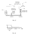
- FIG. 27 is a schematic illustrating structure associated with a currently preferred embodiment of the invention adapted to ensure presence of a bubble-free fluid sample
- FIG. 28 is a plot of impedance representative of measured values during a test performed with the embodiment of FIG. 27 ;
- FIG. 29 illustrates structure of an air bubble remover that may be included in certain embodiments of the invention.
- FIG. 30 is a cross-section view taken through section 30 - 30 in FIG. 29 ;
- FIG. 31 is a top view of a portion of structure carried by a cartridge structured according to certain aspects of the instant invention and adapted for serial and/or parallel interrogation of a fluid sample through a plurality of differently structured interrogation channels;
- FIG. 32 is a side cross-section view of the structure illustrated in FIG. 31 ;
- FIG. 33 is a plan view of structure carried by an embodiment of a cartridge according to certain aspects of the instant invention and operable selectively to permit flow of sample fluid for interrogation;
- FIG. 34 is a side cross-section view of the mixing chamber in FIG. 33 ;
- FIG. 35 is a side cross-section view of a chamber in FIG. 33 ;
- FIG. 36 is a side cross-section view of an operable sample chamber portion of a cartridge, including a rupturable container.
- Cartridge 100 includes fluid receiving structure, generally indicated at 104 , embodied as a capillary tube 108 .
- Tube 108 is adapted to receive a fluid sample by way of capillary action.
- One such fluid sample may conveniently be acquired from a drop of blood obtained from a prick wound.
- an operable receiving structure 104 may be adapted to receive fluid dispensed from a pipette, syringe, or other fluid dispensing structure.
- cartridge 100 is constructed as such a sufficiently simple and inexpensive device to permit its disposal subsequent to a single use.
- a preferred cartridge has a small form-factor to reduce its required storage volume and constituent material cost.
- One convenient size for a cartridge is about the size of a book of paper matches.
- Certain preferred cartridges may be embodied having a size approximately the size of a thick credit card.
- Grip-assist structure 110 may be provided to facilitate handling of a cartridge 100 .
- a window 112 can be provided for a user to visually ensure blood, or other sample fluid, is present inside the cartridge 100 .
- a vent 116 in communication with a sample chamber or channel through the cartridge 100 may be included to assist fluid flow from an external fluid source, through an entrance orifice, and into the device 100 .
- Such vent 116 if present, can typically be occluded subsequent to charging the CBC device's sample-holding reservoir.
- vents can be disposed at selected fluid-flow control points along a flow channel through a cartridge, such as a cartridge 100 .
- a cartridge such as a cartridge 100 .
- Such vents may be opened and closed to provide a convenient control arrangement, in cooperation with a pump arrangement, such as a low pressure or vacuum source coupled to the vent opening, to urge selective flow of the sample through the cartridge.
- a fluid sample may be pressurized to cause fluid flow, in which case valves and vents may be used to control such flow.
- a currently preferred hydrophobic membrane includes polytetrafluoroethylene (PTFE), although gas-permeable membranes that are manufactured from alternative materials, and which are resistant to fluid flow, are also workable.
- PTFE polytetrafluoroethylene
- a plurality of electrical contact pads are carried by a cartridge 100 in an arrangement adapted for coupling to an external electronic device.
- each of the electrical contacts 120 are in electrical communication with a selected electrode disposed in an interrogation portion of a MEMS chip 124 .
- One or more apertures 125 , 126 may be included to form structure providing access to permit electrical coupling of an external device to the electrical contact pads 120 .
- a cartridge 100 includes a tape layer 128 holding a gasket 132 in fluid sealing contact on top of a MEMS chip 120 and in reception in cartridge body 136 .
- An operable gasket 132 may be formed from silicone sheet.
- a body 136 may be plastic injection molded, cast, or machined.
- a channel is formed through a cartridge 100 providing fluid communication between fluid receiving structure 104 and a waste chamber, such as on-board waste chamber 140 .
- a waste chamber may also be located external from a cartridge.
- Connection structure may be disposed in fluid communication with the channel and arranged to couple with an external fluid motive source operable to drive fluid flow through a channel in a cartridge.
- Connection structure 144 may be configured as one or more illustrated orifice 148 to permit application of a pump or vacuum to urge fluid flow through a channel. It is within contemplation for connection structure 144 to include a length of conduit, or coupling structure, such as a hose barb.
- a hydrophobic membrane barrier (not illustrated) is disposed in association with waste reservoir 140 to permit evacuation of air from a cartridge along a vent path while resisting escape of fluid from the cartridge.
- the waste chamber 140 may include an absorbent material (such as a portion from a tissue sold under the trade name KimWipes) to participate in capillary-assisted internal flow, and/or as an aid to contain blood inside a CBC device 100 to resist spread of blood-born ailments subsequent to use of the device.
- Preferred embodiments may further, or also, include a hermetically sealable structure operable to contain the blood, or other fluid sample.
- closure structure may also be provided operable as a cap effective to occlude the blood collection tube 108 , or fluid receiving structure 104 having another configuration.
- FIGS. 3-5 illustrate additional details of construction of one embodiment of a MEMS chip 124 according to certain principles of the invention and adapted to perform a CBC test.
- a representative MEMS chip 124 is sized about 1 ⁇ 2 cm by about 1 cm.
- Certain MEMS chips 124 can be made by conventional photomasking and etching techniques.
- the MEMS chip 124 illustrated in FIGS. 3-5 provides a microchannel 152 that is sized to permit single-file cell passage of the red blood cells (RBC).
- Microchannel 152 is formed in the typically 5-20 micrometer thick epoxy photoresist layer 156 .
- the photoresist layer 156 is typically carried on a substantially dielectric substrate layer 158 .
- a downstream vacuum is applied to start the internal fluid/particle flow through the microchannel 152 of the illustrated MEMS chip 124 .
- the fluid sample is urged to flow from receiving structure 104 to a receiving chamber 159 on-board chip 124 .
- Receiving chamber may be an enlarged chamber, or simply a continuation of structure leading from fluid receiving structure 104 .
- the thinned or modified whole blood flows through the microchannel 152 and over a plurality of surface electrodes 164 disposed to permit direct interrogation of the fluid sample portion that is disposed inside the microchannel 152 and between one or more pairs of electrodes 164 . Fluid flow then continues along conduit portion 168 , through exit 170 , and into holding chamber 172 .
- Holding chamber 172 may constitute a waste chamber 140 , or may be in fluid communication with an off-chip waste chamber 140 .
- Certain cartridges 100 constructed according to the invention may include additional factors, such as diluents, solvents, interactors such as antigen-bound beads, or inhibitors of various kinds, which may be pre-loaded in operable position to interact with an introduced fluid/particle mix prior to interrogating that mix.
- Such reservoirs may be a component of a cartridge 100 , or part of a chip 124 .
- a reservoir holding diluent and/or a lysing agent desirably is arranged for mixing, typically at the start of a CBC test, with an introduced whole blood sample.
- the diluent may further include a blood anticoagulant (e.g. EDTA or Heparin), to resist blood clot formation in the MEMS sensor chip 124 .
- a blood anticoagulant e.g. EDTA or Heparin
- an interrogation platform 176 includes alignment structure, generally indicated at 180 , adapted to receive a cartridge 100 in an installed substantially fixed interrogation orientation and to resist installation of the cartridge in an improper orientation.
- One operable alignment structure 180 includes a socket 184 , which may be configured to provide visual orientation clues to an operator to assist in orienting a cartridge 100 .
- structure is provided to maintain a cartridge 100 in a substantially fixed installed position. As illustrated in FIG. 6 , biased retaining structure 188 is adapted to couple with cooperating held structure 192 of a cartridge 100 to hold the cartridge in such substantially fixed installed position.
- the interrogation platform 176 carries electrode-probes (not illustrated) disposed to make physical contact with electrode contact pads 120 of the MEMS chip.
- One way to make such contact includes rotating a probe-carrying platen about axis 194 . Contact may then be made with pads 120 by way of electrical probes having a push-pin configuration. It is within contemplation that insertion of an alternatively structured cartridge 100 can place pads 120 into reception in cooperating electrical connector structure, such as by way of an edge connector.
- the electrode contact pads 120 individually are in electrical communication with individual surface electrodes 164 disposed in the interrogation flow channel 152 .
- An electrical signal may therefore be applied to pads 120 by electronic interrogation circuitry 196 associated with the interrogation platform 176 (the signal typically having a radio frequency), and impedance may be measured, across pairs of the electrodes 164 .
- Fluid flow of a test sample can be urged by operation of a fluid motive source 198 associated with an interrogation platform 176 .
- a fluid motive source 198 may be configured to couple with connection structure 144 of the cartridge 100 .
- Passage of cells over successive downstream pairs of electrodes during a test can be used to determine time shifting of the impedance signal between those successive pairs of electrodes 164 using a cross-correlation technique.
- the time of flight of the cells used in conjunction with the cross-sectional area of microchannel 152 , may be used to calculate volumetric flow rate of the blood sample.
- Blood-cell types can be determined based upon their unique impedance signals. Discrimination may be made between platelets, RBCs and white blood cells (WBC), as well as between types of WBCs.
- FIGS. 7 and 8 An alternative embodiment of a disposable, single-use, cartridge, structured according to certain principles of the invention and generally indicated at 200 , is illustrated in FIGS. 7 and 8 .
- Cartridges 200 may be embodied to perform CBC tests, among other uses.
- Fluid receiving structure 104 of cartridge 200 includes a sample fluid channel entrance orifice disposed in a position effective to receive blood, or other fluid carrying particulate matter, from a fluid source for capillary, or otherwise assisted, flow into a receiving chamber 159 inside the device 200 .
- the illustrated embodiment 200 includes a MEMS chip 124 housed in cartridge body 204 .
- a gasket 208 is placed on top of chip 124 .
- a first vacant portion 212 of the gasket 206 forms walls for the blood channel and receiving chamber.
- a second vacant portion 216 of the gasket 206 forms walls for a holding chamber 172 in which to contain interrogated fluid.
- the gasket 208 and chip 124 are maintained in registration in body 204 by tape layer 220 .
- a tape layer 220 typically includes a self-adhesive surface disposed to form a sealed cover operable as a top to the chambers 159 , 172 and fluid channel through the chip 200 .
- One or more suction orifice 224 and one or more vent hole 228 are generally provided to provide communication of gases through the tape layer 220 , as illustrated.
- the vent hole(s) 228 is/are typically occluded subsequent to charging the receiving chamber 159 with fluid.
- Illustrated tape layer 220 includes an open portion 132 providing access structure configured to permit electrical coupling of an external device to the plurality of electrical contact pads 120 carried by cartridge 200 .
- a vacuum may be applied to the MEMS chip 124 by way of a flexible diaphragm that is integrated into an alternatively structured cartridge 200 .
- a vacuum enhances assurance that no blood leaves the cartridge subsequent to a CBC test, and thereby decreases chance of spreading blood-born disease.
- FIG. 9 illustrates another arrangement of structure desirably incorporated into a MEMS chip.
- the structure illustrated in FIG. 9 includes a receiving chamber 159 to hold a quantity of fluid and particulate matter, such as whole blood.
- a filter 160 may be provided to resist developing an undesired occlusion in a microchannel 152 by debris, or particles of too large size to pass through the microchannel 152 .
- the electrodes 164 and corresponding contact pads 120 are illustrated in one alternative side-mounted configuration.
- the illustrated contact pads 120 are numbered 1-4 in series, and are in electrical communication with cooperating electrodes 164 .
- the fluid flowing along the microchannel may be interrogated between pairs of electrodes, which generally are disposed on the “floor” of the channel.
- fluid mix is interrogated between successive pairs of electrodes.
- fluid it is within contemplation for fluid to be interrogated between overlapping pairs of electrodes.
- one typical arrangement interrogates fluid/particles between electrodes corresponding to pads 1 and 2 , and between subsequent downstream electrodes corresponding to pads 3 and 4 .
- a second alternative overlapping electrode setup includes interrogating fluid/particles flowing between electrodes 1 and 4 , while also interrogating fluid/particles flowing between electrodes 2 and 3 .
- a third interrogation scheme interrogates fluid/particles between electrodes 1 and 2 , and electrodes 2 and 3 .
- Electrodes may be shaped and configured to provide enhanced interrogation of a particle bearing fluid. Electrodes used in certain MEMS chips 124 may be characterized as surface-mounted electrodes, which are disposed in series along a floor of an interrogation conduit, such as channel portion 152 , at a plurality of axially spaced apart locations. Each surface-mounted electrode is typically disposed substantially on only one side of a cross-section through the channel 152 . Such single-sided placement permits electrical communication between electrodes in a direction substantially in parallel with the axis of the channel. It is also within contemplation for surface-mounted electrodes to be configured for electrical communication across the channel. FIGS. 10B-E illustrate various electrode configurations within contemplation.
- FIG. 10B illustrates twin pairs of surface-mounted electrodes, generally indicated at 232 .
- FIG. 10C illustrates Coulter-style electrodes, generally indicated at 236 .
- FIG. 10D illustrates a twin Coulter combination of electrodes, generally indicated at 238 .
- FIG. 10E illustrates double-sided electrodes, generally indicated at 240 , which are configured to permit electrical communication across an interrogation channel.
- FIG. 11 illustrates a MEMS chip 242 adapted to provide flow in a four radial directions from an axial direction of fluid flow into a fluid entrance chamber 244 .
- Interrogation zones are provided by sensors including electrodes located in interrogation channels 152 that permit fluid communication between chamber 244 and a plurality of holding chambers 248 . Any number of interrogation zones may be provided in separate interrogation channels 152 forming spokes radiating out from a central chamber 244 , within dictates of manufacturing constraints.
- Such plurality of hydraulically parallel sensors permit performing a plurality of simultaneous parallel electrically-based interrogations on divided subportions of a fluid sample.
- a chip 242 may be arranged in an alternative construction to provide fluid flow into chamber 244 that is in the plane of the page.
- Such an in-plane fluid flow arrangement may be provided from a single supply conduit 252 and through a plurality of separate interrogation channels 152 .
- FIG. 12 One such in-plane fluid flow arrangement is illustrated in FIG. 12 , embodied in MEMS chip 256 .
- holding chamber 248 may be located either on-board of a MEMS chip, or on a cartridge 260 . It is within contemplation to perform either parallel or serial analyses, with embodiments such as illustrated in FIGS. 11 and 12 , by applying a fluid motive source, such as a vacuum, selectively to cause fluid/particle flow through an individual channel 152 .
- a fluid motive source such as a vacuum
- MEMS chip 264 An alternative and currently preferred MEMS chip, generally indicated at 264 , is illustrated in FIG. 13 .
- Chips 264 can range in size from large to small, with a preferred chip being relatively small, at perhaps about 1 ⁇ 2 cm 2 in surface area.
- MEMS chip 264 includes a barrier element 268 disposed between a first stimulated electrode 270 and a second stimulated electrode 272 .
- Barrier element 268 includes a detection electrode 274 sandwiched between a substantially dielectric first layer 278 and a substantially dielectric second layer 282 .
- the dielectric material is desirably effective to resist electrical communication between each of the detection electrode 274 , the first stimulated electrode 270 , and the second stimulated electrode 272 .
- the detection electrode 274 is disposed inside a Coulter style orifice formed by at least a portion of interrogation channel 286 .
- Channel 286 form a conduit through detection electrode 274 .
- a fluid-contacting area of detection electrode 274 circumscribes a local portion of the conduit 286 .
- the conduit 286 provides an electrical continuity between first stimulated electrode 270 , detection electrode 274 , and second stimulated electrode 272 via electrically conductive liquid 290 communicating through conduit 286 . Therefore, a detection zone is formed in the vicinity of a detection electrode 274 of an electrical sensor formed inside a conduit 286 .
- a direction of fluid flow through the MEMS chip is indicated by arrow 294 .
- the interrogation channel 286 typically has an approximately circular cross-section for simplicity of manufacture. Alternative configurations are also workable, including rectangular and oval, among others.
- a channel 286 can be manufactured by micromachining methods, including laser drilling, water drilling, plasma etching, and the like.
- the currently preferred “small” sizes for a chip 264 encompass channels 286 having diameters between about 3-150 microns. Larger devices constructed according to principles of the invention may simply be drilled with conventional mechanical machining methods, including drilling, or with water jet or laser cutting. In devices adapted to perform a CBC test, the diameter of an interrogation channel may be around 10 micrometers. In a device adapted to perform a CD4+ test, the channel may have a diameter of about 35 micrometers. FIGS.
- a channel 286 may be constructed to have an entrance 298 that forms a metering structure, or may include a restriction within the channel 286 , such as illustrated in FIG. 14 .
- suitable coatings are applied to surfaces of a chip or cartridge that contact sample fluids.
- Such coating arrangement can be provided to reduce the clotting cascade in whole blood samples, for example.
- Coatings operable in sensors for use with such blood samples include Teflon, heparin, and PRO-based materials.
- Each insulating layer 278 , 282 may be formed from any material resistant to conductance of electricity.
- the insulating layer simply must function to place electrodes in electric isolation from each other, except for communication along (typically) a proscribed fluid path.
- the insulators it is currently preferred for the insulators to be formed from flexible, film-like plastic materials, including polyamides and polyesters such as Mylar and Kapton, respectively.
- Such films may be on the order of 0.0001 to 0.010 inches (2-200 microns) in thickness, although thinner or thicker materials may be used, as desired for particular applications.
- Chips or sensors 264 with resisting layers 278 , 282 made from thin film materials are sometimes characterized as flexible chips.
- the instant invention can be embodied using virtually any thicknesses for substrate insulators and electrodes, However, thickness of insulator and electrode layers, and channel sizes, in a particular sensor are typically sized in accordance with the intended use of that particular sensor. As non-limiting examples, it is within contemplation to form an alternative insulator layer from nonconductive sheet or plate material, or even from a portion of an electronic circuit board.
- Electrodes are generally made from metal or alloys of metals, including Aluminum, Platinum, Gold, Copper, Silver, Chromium, Iridium, Titanium, and the like, although any other operable electrically conductive material would suffice. It is currently preferred to coat the interrogation electrode (and sometimes one or more of the excited electrodes), onto an insulator film to improve material handing characteristics during assembly of the sensor. The coating operation may be carried out by electroplating, electro-chemical deposition, or using some other known method, such as sputtering or electro-deposition techniques, and the like. It is further within contemplation to incorporate micro-machining methods, such as masking and etching, as well as screen printing techniques and laser etching, to formulate individual electrode structures.
- micro-machining methods such as masking and etching, as well as screen printing techniques and laser etching
- a voltage induced by a signal generator 302 is applied to stimulate each of electrodes 270 and 272 .
- the applied voltage, or electric signal is a fluctuating voltage, typically having opposite sign (V + and V ⁇ ) and the same magnitude at each stimulated electrode.
- a passive voltage V m corresponding to the imposed signal, and any effect due to presence of one or more particles, is measured at the interrogation electrode 274 disposed between the stimulated electrodes 270 and 272 .
- the measured signal from chip 264 changes sign, and thereby causes a more distinct measured signal when compared to a signal generated in chips embodied as illustrated in FIG. 3 .
- the arrangement illustrated in FIG. 13 dramatically improves signal-to-noise ratio. Furthermore, the effect on the magnitude of measured voltage at the detection electrode due to particle departure from a consistent path is significantly reduced.
- FIGS. 16-18 Details of construction of a currently preferred flexible MEMS chip, generally indicated at 310 , will now be made with reference to FIGS. 16-18 . It is currently preferred to provide alignment features, such as the illustrated holes 314 , to assist in alignment of the constituent structures as respective layers forming the device are “stacked” on one another.
- the stacked components form a sensor assembly 310 that may be regarded as a “chip”.
- a plurality of interrogation channels 286 may be provided, numbering from one to as many as desired, up to a limit perhaps imposed by manufacturing or data acquisition considerations.
- the device illustrated in FIGS. 16-18 has eight interrogation channels 286 that may be used to perform a simultaneous parallel analysis of the fluid flowing therethrough. It is currently contemplated to manufacture sensor devices with up to 200, or more, parallel channels. In any case, it is currently preferred to form the channel 286 to provide a continuous stretch of electrode material disposed as a ring section of the channel. Such an encircling electrode configuration tends to average out the signal produced in the measurement electrode 274 , substantially regardless of the relative position of an undersize particle with respect to the channel centerline.
- each channel 286 is arranged to pass through the stimulated electrode 270 .
- a contact pad 318 is configured to communicate an electric signal from an external device along electric trace element 322 to the electrode 272 .
- the electrode 270 , electric trace element 322 , and contact pad 318 may be patterned on one side of dielectric layer 278 .
- Electrode 270 forms a plurality of electrodes, one associated with each channel 286 , that are electrically in common.
- one or more detecting electrode 274 can be patterned on the opposite side of layer 278 , and arranged to encompass a desired area in vertically stacked relation to the electrode 270 . As illustrated, eight such electrodes 274 are provided in the embodiment of FIGS. 16-18 . Each illustrated electrode 272 includes a contact pad 326 that communicates electrically with the electrode through electric trace element 330 . Note that a stretch of a channel 286 passes through a respective detecting electrode 272 .
- the bottom side of the sensor 310 carries stimulated electrode 272 and contact pad 334 for connection of the electrode to external signal generator, such as signal generator 302 .
- Contact pad 334 communicates an electric signal from a signal generator to the electrode 272 by way of an electric trace element 338 .
- electrode 272 , trace element 238 , and contact pad 334 are patterned on insulating layer 282 prior to assembly of the layers to form a chip 310 .
- channels 286 continue through the stimulated electrode 272 .
- Electrode 272 forms a plurality of electrodes, one associated with each channel 286 , that are electrically in common.
- Sensors formed in certain chip embodiments are desirably configured to provide spacing between electrodes with the spacing being on the order of the size of a characteristic size, such as a “diameter” of a particle of interest. If the spacing is even smaller, such as one-half the characteristic dimension, the resolution of the sensor portion may be even better.
- a characteristic size such as a “diameter” of a particle of interest. If the spacing is even smaller, such as one-half the characteristic dimension, the resolution of the sensor portion may be even better.
- a CBC or CD4 device it is currently preferred to manufacture a substrate layer from Kapton, due to the high melting temperature (350° C.) inherent in Kapton.
- the electrodes may conveniently be patterned on such substrate, and a second insulating layer of Mylar can be heat bonded to the substrate layer.
- the Kapton layer is typically about twice the thickness of the Mylar layer in currently preferred embodiments of the invention.
- Such difference in thickness of insulating layers can result in a bias, or a signal offset from zero in the absence of a particle, in a signal measured at a detecting electrode 274 sandwiched between the layers.
- Such bias can be reduced or eliminated by forming a larger entrance or exit, such as entrance 298 in FIG. 14 , in the thicker insulating layer.
- An optimized such entrance can be configured to provide a substantially electrically equivalent resistance between each stimulated electrode and a detecting electrode sandwiched therebetween.
- FIGS. 13-18 While a single interrogation “layer” is illustrated in FIGS. 13-18 , it is within contemplation to form alternative MEMS chips having a plurality of stacked interrogation layers, to provide a plurality of interrogation electrodes arranged along an axis of the interrogation channel 286 . Such alternative chips would enable serial analysis of a sample along a single conduit 286 . Furthermore, certain alternative serially stacked chips including a plurality of channels 286 would be capable of simultaneous parallel and serial analysis of a fluid sample.
- FIGS. 19 and 20 illustrate an experimental set up structured according to principles of the invention, and data corresponding to the illustrated arrangement, respectively.
- FIG. 19 depicts three particles; blood cells of different types, prepared to travel in succession through an interrogation channel 268 embodied in a thin film chip structured according to principles of the instant invention, such as chip 310 .
- the illustrated channel 286 is desirably about 10 micrometers in diameter, and can be between about 4 to about 400 micrometers, or so, in length. In such devices, the channel diameter can range between about 3 to about 150 micrometers, or so.
- the data shown in FIG. 20 assume an approximately constant and uniform travel velocity of the particles through the channel.
- the red blood cell (RBC) is smaller than the channel diameter, but produces a distinctive signal.
- the white blood cell (WBC) is larger than the channel, but can extrude therethrough. Contact between the WBC and the interrogation electrode produces a maximum signal, essentially “railing” the device.
- the platelet being of much smaller size, causes a lesser, albeit a distinct and discernable, signal.
- FIGS. 21A and 21B illustrate one exemplary arrangement forming a single-use cartridge constructed according to certain principles of the invention, and generally indicated at 350 .
- the cartridge 350 may include a snap-on cap 354 , as illustrated, to resist escape of a portion of a loaded fluid sample through the sample collection structure 104 .
- Snap-on cap 354 may maintain sterility before and after loading the sample.
- a cap 354 may also contain one or more fluids for use during a test, such as a diluent, solvent, or inhibitors of various kinds, that may be pre-loaded in operable position to interact with an introduced fluid/particle mix prior to interrogating that mix.
- a representative cartridge 350 may be between about 1 and 3 inches in a longest direction, although longer and shorter cartridges are operable.
- the body 358 of cartridge 350 is configured to provide a measure of protection to contact pads 120 , and to couple them in electrical communication with an interrogation platform, such as platform 176 .
- FIGS. 22 and 23 illustrate operable embodiments of electronic interrogation circuitry 196 that may be associated with an interrogation platform 176 .
- Such circuitry may include a multiplexor 362 to cycle signals and/or measurements between a plurality of electrodes.
- a signal generator 302 is adapted to output a desired signal to a plurality of contact pads on the MEMS chip being interrogated.
- An A/D converter 366 typically modifies the collected analog detection signal for use by another device.
- Representative such devices include a computer platform 382 , such as a PDA, hand-held computer, and a desktop or laptop computer.
- Electronic elements including one or more band pass filter 370 , amplitude detector 374 , and phase detector 378 may be included in an operable electronic arrangement 196 .
- FIG. 23 illustrates a currently preferred arrangement for electronics 386 that may be included in circuitry 196 .
- Electronic arrangement 386 includes a plurality of filters 390 and A/D converters 394 adapted to interface with an A/D controller 398 .
- a signal received from a detecting electrode is routed through a filter 390 and A/D converter 394 to a buffer 402 and data serializer 406 for output as a signal modified for use by a computer platform 382 .
- a signal from a switchable signal generator 410 may be selectively applied through buffers 414 to a plurality of stimulated electrodes, such as 270 and 272 in FIG. 13 .
- a clock 418 may be used to drive the signal generator 410 .
- a power supply 422 may provide power to the components through a switch, generally indicated at 426 .
- FIG. 24 illustrates structure, generally indicated at 450 , that desirably is provided on certain cartridges according to certain aspects of the invention.
- the input reservoir may be a chamber, or a portion of the channel from receiving structure 104 flowing through a cartridge.
- a reagent reservoir 458 may be disposed in a cap 354 , or on-board a cartridge. In any case, if present, a reagent reservoir 458 is generally placed into fluid communication with the sample for mixing prior to interrogation in a sensor portion of the cartridge.
- a chamber 462 defining a known volume in which to select a portion of the introduced fluid sample for evaluation in the sensor portion of the cartridge.
- Such chamber 462 may conveniently be defined between a first valve 464 and second valve 466 .
- the chamber 462 may be sequentially used to measure a quantity of sample fluid, and a quantity of reagent. Fluids may be drawn into an overflow chamber 470 by a vacuum 474 , or other motive source operable to urge fluid motion.
- the overflow chamber can operate to verify, or to ensure, that complete filling of the chamber 462 occurs.
- a hydrophobic membrane 478 is typically positioned to permit gasses to exit the cartridge, but to resist escape of fluids from the chamber 470 .
- a hydrophobic membrane such as membrane 478
- membrane 478 may be formed from a thin sheet of Teflon, or Teflon-like material. Certain Teflon-based materials are also operable. It is within contemplation to form a membrane from Teflon coated or impregnated materials. Certain other materials, such as polystyrene, may be formed into an alternative workable gas permeable and fluid retaining membrane.
- a central mixing chamber 482 may be included on a cartridge to permit mixing of a reagent with the introduced fluid sample to form a modified test fluid. Fluid can be drawn into mixing chamber 482 by a selective suction of gasses through a hydrophobic membrane 486 .
- a valve 490 may be included on a cartridge as a fluid-flow control device. Subsequent to test sample preparation, such valve 490 may be opened and fluid may be urged to flow through one or more sensors of a MEMS chip, such as chip 124 or 310 . In most cases, test fluids are urged to flow from a MEMS chip along a channel 488 into a waste chamber 490 contained in the cartridge.
- a venting membrane 494 desirably is provided in association with the chamber 490 to permit gasses to exit the cartridge while resisting escape of fluids.
- Membrane 494 in combination with a fluid motive source and one or more valves 464 , 466 and 490 serves as a way to facilitate control of fluid flow through a cartridge.
- a cartridge include dispensing structure, generally indicated at 498 , for a reagent that is confined in packaging, such as a pouch or packet 500 .
- the pouch can be made from foil, plastic, or other material effective to form a rupturable membrane in which a fluid may be temporarily confined.
- a convenient way to dispense the reagent from a packet 500 is also illustrated in FIGS. 25 and 26 , where a plunger 504 is adapted to press packet 500 into engagement with rupturing structure 508 .
- Certain operable rupturing structure 508 can be embodied as a needle-like pointed object, or may provide a sharp edge, such as a knife edge, or a jagged edge.
- the plunger 504 may also be employed to urge flow of the reagent through a cartridge as illustrated by arrow 510 , e.g. to mix with a sample in the cartridge. It is also within contemplation for piercing structure 508 to be associated with a plunger 504 , such as illustrated in FIG. 36 .
- a cartridge may include bubble detection structure.
- One workable bubble detection structure is indicated generally at 512 in FIG. 27 .
- An electrode 514 is disposed upstream of an area to be monitored for presence of bubbles.
- a second electrode 516 is disposed downstream of the monitored area.
- An impedance monitor 518 is applied in-circuit between the electrodes 514 , 516 to monitor impedance between them.
- the graph illustrated in FIG. 28 represents data that might be collected during operation of the bubble monitor 512 .
- time period 520 presence of one or more bubbles causes high impedance. Once the air or gasses are removed or replaced with gas-free solution, a discernibly lower impedance is measured.
- a bubble removing structure desirably is included in certain cartridges to ensure no bubbles are present in a sample prior to conducting a test.
- An operable bubble removing structure 522 may be formed by associating a hydrophobic membrane 524 with a chamber or portion of a channel 526 . A vacuum applied to one side of the membrane is therefore effective to remove gasses from the fluid retained on an opposite side of the membrane 524 .
- the bubble remover 522 is associated with a chamber having a known volume, effective to produce a bubble-free known volume of fluid for testing by a MEMS chip 124 , 310 . In such preferred embodiments, a particle count-per-known-volume may be obtained. Once the known volume is obtained, a vent or valve 528 may be opened to permit urging the test sample fluid through the MEMS chip 124 , 310 for interrogation in a sensor portion of the chip.
- a cartridge may carry structure arranged to deliver portions of a sample through selected channels to different sensors of a MEMS chip.
- One such arrangement is indicated generally at 530 in FIGS. 31 and 32 .
- Fluid from a chamber 532 flows through a channel portion 534 to valve 536 .
- Valve 536 may be oriented to permit flow through either of channel portion 538 or channel section 540 .
- Channel portion 538 terminates at entrance area 542 near sensor portion 544 of the MEMS chip 124 , 310 .
- Channel portion 540 terminates at area 546 near sensor portion 546 of the MEMS chip 124 , 310 .
- the sensors 544 and 546 may be similar to each other, or may be differently structured to interrogate different populations of particles.
- each sensor 544 , 548 may be sized in agreement with particles of a certain size. Tested sample fluid downstream of the MEMS chip then flows through channel extension 550 to waste chamber 552 . Fluid flow may be urged by a vacuum 554 applied through a membrane 556 .
- Structure 558 desirably carried by a cartridge configured to perform a CD4+ test is generally indicated at 558 in FIG. 33 .
- Structure 558 includes blood receiving structure or chamber 104 , coupled to a fluid metering arrangement, such as indicated by valve 560 .
- a bore 561 in valve 560 may be configured to contain, and thereby select, a desired known volume of sample fluid.
- a plurality of reagent chambers 562 - 566 desirably are disposed for introduction of reagents for sample manipulation.
- chamber 562 may contain solutions of latex or magnetic beads.
- Chambers 564 and 566 hold quantities of saline, and/or other fluids, for washing, treating, or diluting the test sample in mixing chamber 482 .
- reagent reservoirs may be adapted to dispense known quantities of fluids for selected sample manipulation.
- Fluid downstream of mix chamber 482 is directed for flow toward waste chamber 468 , or through the MEMS chip 124 , 310 .
- valve 536 may be associated with the mix chamber 482 .
- An impedance monitor 518 desirably is included to ensure full charging of the metering valve 560 during introduction of the sample for a test.
- Structure to hold-back certain particles, such as magnet 569 is also desirably included in operable association with the cartridge.
- the arrangement 558 may be used, in one nonlimiting example, as follows: A sample fluid is introduced to receiving structure 104 , and drawn through metering valve 560 using a vacuum source 570 applied through a hydrophobic membrane 572 associated with waste chamber 568 (see FIG. 35 ). A low impedance measured by monitor 518 indicates when the valve 560 is fully charged, and air is removed in the fluid stretch disposed between its electrodes (and from the known-volume conduit 561 ). Valve 560 is then rotated, to the illustrated position, to permit reagent including antigen-bound latex beads from chamber 562 to flow and urge the selected volume of sample fluid to flow toward, and mix in, chamber 482 .
- Latex monocyte blocking beads and fluid are used essentially to push the known volume of selected sample fluid into the mixing chamber.
- antigen-bound magnetic beads and solution is injected into chamber 482 from reagent chamber 574 and attach to the CD4 T cells, a magnetic field from magnet 569 can be applied on the mixing well to hold the bound cells in place during a first washing cycle using fluid from say, reservoir 564 .
- a second washing cycle from say, reservoir 566 can resuspend the bound cells in the diluent “wash” media.
- Valve 536 is then adjusted to direct flow of the washed test sample through MEMS chip 124 , 310 for counting.
- the known volume of blood is pushed into mixing chamber 482 using magnetic CD14 monocyte beads from chamber 562 .
- an external magnetic source is turned on and CD4+ latex beads are injected into the mixing chamber 482 from one of the lower-illustrated reagent chambers (say chamber 564 ).
- RBC lysing reagent is injected into the mixing chamber 482 from wash chamber (say from chamber 566 ) to lyse all the RBCs but not the WBCs.
- all of the WBCs are counted and the WBCs with the CD4+ latex beads attached (killer T cells) can be distinguished from regular WBCs because of their larger apparent diameter due to all of the small attached latex beads.
- This method provides both an absolute CD4 count and a WBC count. Such an alternative method may sometimes be used in milk WBC counting and human WBC counting with differential analysis.
- Another method of use of certain embodiments of the invention encompasses removal of bubbles from a test sample.
- One such method includes the steps of: loading a sample of fluid into the cartridge; urging a quantity of the sample into the known volume selection chamber; monitoring the electric impedance through the known volume selection chamber to determine when the sample is bubble free; urging the known and air bubble free volume of test fluid to flow past the sensor for interrogation by the platform; and then, disposing of the cartridge. Variations on such bubble-free solution testing can be performed with or without electric impedance monitoring, mixing with diluent, etc.
Abstract
Description
Claims (10)
Priority Applications (1)
| Application Number | Priority Date | Filing Date | Title |
|---|---|---|---|
| US12/639,095 US8329437B1 (en) | 2004-07-29 | 2009-12-16 | Disposable particle counter cartridge |
Applications Claiming Priority (3)
| Application Number | Priority Date | Filing Date | Title |
|---|---|---|---|
| US59235004P | 2004-07-29 | 2004-07-29 | |
| US19398405A | 2005-07-29 | 2005-07-29 | |
| US12/639,095 US8329437B1 (en) | 2004-07-29 | 2009-12-16 | Disposable particle counter cartridge |
Related Parent Applications (1)
| Application Number | Title | Priority Date | Filing Date |
|---|---|---|---|
| US19398405A Division | 2004-07-29 | 2005-07-29 |
Publications (1)
| Publication Number | Publication Date |
|---|---|
| US8329437B1 true US8329437B1 (en) | 2012-12-11 |
Family
ID=47289085
Family Applications (1)
| Application Number | Title | Priority Date | Filing Date |
|---|---|---|---|
| US12/639,095 Active 2025-11-16 US8329437B1 (en) | 2004-07-29 | 2009-12-16 | Disposable particle counter cartridge |
Country Status (1)
| Country | Link |
|---|---|
| US (1) | US8329437B1 (en) |
Cited By (27)
| Publication number | Priority date | Publication date | Assignee | Title |
|---|---|---|---|---|
| US20150346075A1 (en) * | 2014-06-03 | 2015-12-03 | Intellicyt | Flow Cytometry Sample Separation Methods and Apparatus |
| US20150362420A1 (en) * | 2014-06-13 | 2015-12-17 | Wafergen, Inc. | Systems for single or multiple cell counting and dispensing |
| US20160033435A1 (en) * | 2012-05-10 | 2016-02-04 | Industry-Academic Cooperation Foundation, Yonsei University | Method of measuring biological sample properties and biological sample property measuring apparatus |
| WO2016034564A1 (en) * | 2014-09-07 | 2016-03-10 | Selexis S.A. | Microfluidic methods and cartridges for cell separation |
| US9434937B2 (en) | 2011-03-07 | 2016-09-06 | Accelerate Diagnostics, Inc. | Rapid cell purification systems |
| US20170056880A1 (en) * | 2015-08-26 | 2017-03-02 | EMULATE, Inc. | Fluid connections using guide mechanisms |
| US9657327B2 (en) | 2003-07-12 | 2017-05-23 | Accelerate Diagnostics, Inc. | Rapid microbial detection and antimicrobial susceptibility testing |
| US9677109B2 (en) | 2013-03-15 | 2017-06-13 | Accelerate Diagnostics, Inc. | Rapid determination of microbial growth and antimicrobial susceptibility |
| US9757728B2 (en) * | 2016-01-26 | 2017-09-12 | Lidong Qin | Microfluidic aliquoting for single-cell isolation |
| WO2017161057A1 (en) * | 2016-03-15 | 2017-09-21 | Ei Spectra, Llc | Whole blood staining preparation cartridge and system |
| WO2017180549A1 (en) * | 2016-04-12 | 2017-10-19 | Dots Technology Corp. | Allergen detection using magnetics |
| US9841422B2 (en) | 2003-07-12 | 2017-12-12 | Accelerate Diagnostics, Inc. | Sensitive and rapid determination of antimicrobial susceptibility |
| US20180001319A1 (en) * | 2014-12-16 | 2018-01-04 | Medcom Advance, S.A. | Analysis device, analysis apparatus for identification of analytes in fluids and use of the analysis device |
| WO2018022026A1 (en) * | 2016-07-26 | 2018-02-01 | Hewlett-Packard Development Company, L.P. | Microfluidic apparatuses for fluid movement control |
| US10023895B2 (en) | 2015-03-30 | 2018-07-17 | Accelerate Diagnostics, Inc. | Instrument and system for rapid microogranism identification and antimicrobial agent susceptibility testing |
| US10092902B2 (en) * | 2009-04-10 | 2018-10-09 | Canon U.S. Life Sciences, Inc. | Fluid interface cartridge for a microfluidic chip |
| US20180356327A1 (en) * | 2015-11-24 | 2018-12-13 | Hewlett-Packard Development Company, L.P. | Devices having a sample delivery component |
| USD843009S1 (en) * | 2016-10-14 | 2019-03-12 | Illumina, Inc. | Sample preparation cartridge |
| US10253355B2 (en) | 2015-03-30 | 2019-04-09 | Accelerate Diagnostics, Inc. | Instrument and system for rapid microorganism identification and antimicrobial agent susceptibility testing |
| US10254204B2 (en) | 2011-03-07 | 2019-04-09 | Accelerate Diagnostics, Inc. | Membrane-assisted purification |
| EP3556841A1 (en) * | 2018-04-19 | 2019-10-23 | Aglaris Ltd | Disposable cartridge cooperating with a platform in a flexible system for handling and/or manipulating fluids |
| US10591502B2 (en) | 2017-04-03 | 2020-03-17 | Hewlett-Packard Development Company, L.P. | Cassettes including overflow reservoirs |
| US20200240260A1 (en) * | 2019-01-25 | 2020-07-30 | Precision Downhole Services Ltd. | Polymer insulated thermocouple bundles |
| US10913065B2 (en) | 2016-01-22 | 2021-02-09 | Hewlett-Packard Development Company, L.P. | Fluid sensing with control of particle aggregation in sensing zone |
| US11007525B2 (en) | 2015-01-30 | 2021-05-18 | Hewlett-Packard Development Company, L.P. | Vented microfluidic reservoirs |
| US11400452B2 (en) | 2018-06-05 | 2022-08-02 | Chronus Health, Inc. | Devices, cartridges, and sensors for analyzing a biological sample |
| US11585772B2 (en) | 2019-02-08 | 2023-02-21 | Tallinn University Of Technology | Microfluidic method and device |
Citations (15)
| Publication number | Priority date | Publication date | Assignee | Title |
|---|---|---|---|---|
| US5376878A (en) | 1991-12-12 | 1994-12-27 | Fisher; Timothy C. | Multiple-aperture particle counting sizing and deformability-measuring apparatus |
| US6169394B1 (en) | 1998-09-18 | 2001-01-02 | University Of The Utah Research Foundation | Electrical detector for micro-analysis systems |
| US6382228B1 (en) | 2000-08-02 | 2002-05-07 | Honeywell International Inc. | Fluid driving system for flow cytometry |
| US6426615B1 (en) | 1998-02-13 | 2002-07-30 | Shailesh Mehta | Apparatus and method for analyzing particles |
| US6440725B1 (en) | 1997-12-24 | 2002-08-27 | Cepheid | Integrated fluid manipulation cartridge |
| US20020117517A1 (en) | 2000-11-16 | 2002-08-29 | Fluidigm Corporation | Microfluidic devices for introducing and dispensing fluids from microfluidic systems |
| US6454945B1 (en) | 1995-06-16 | 2002-09-24 | University Of Washington | Microfabricated devices and methods |
| US6473551B2 (en) | 2000-11-28 | 2002-10-29 | Photon-X, Inc. | Thin film optical waveguides |
| US6488896B2 (en) | 2000-03-14 | 2002-12-03 | Micronics, Inc. | Microfluidic analysis cartridge |
| US6656431B2 (en) | 1998-05-18 | 2003-12-02 | University Of Washington | Sample analysis instrument |
| US6703819B2 (en) | 2001-12-03 | 2004-03-09 | Board Of Regents, The University Of Texas System | Particle impedance sensor |
| US20040151629A1 (en) | 2003-01-31 | 2004-08-05 | Grant Pease | Microfluidic device with thin-film electronic devices |
| US6794877B2 (en) | 2002-07-31 | 2004-09-21 | International Technidyne Corporation | Apparatus and method for analytical determinations |
| US20050054078A1 (en) | 2003-09-10 | 2005-03-10 | Miller Cary James | Immunoassay device with improved sample closure |
| US20050118705A1 (en) | 2003-11-07 | 2005-06-02 | Rabbitt Richard D. | Electrical detectors for microanalysis |
-
2009
- 2009-12-16 US US12/639,095 patent/US8329437B1/en active Active
Patent Citations (15)
| Publication number | Priority date | Publication date | Assignee | Title |
|---|---|---|---|---|
| US5376878A (en) | 1991-12-12 | 1994-12-27 | Fisher; Timothy C. | Multiple-aperture particle counting sizing and deformability-measuring apparatus |
| US6454945B1 (en) | 1995-06-16 | 2002-09-24 | University Of Washington | Microfabricated devices and methods |
| US6440725B1 (en) | 1997-12-24 | 2002-08-27 | Cepheid | Integrated fluid manipulation cartridge |
| US6426615B1 (en) | 1998-02-13 | 2002-07-30 | Shailesh Mehta | Apparatus and method for analyzing particles |
| US6656431B2 (en) | 1998-05-18 | 2003-12-02 | University Of Washington | Sample analysis instrument |
| US6169394B1 (en) | 1998-09-18 | 2001-01-02 | University Of The Utah Research Foundation | Electrical detector for micro-analysis systems |
| US6488896B2 (en) | 2000-03-14 | 2002-12-03 | Micronics, Inc. | Microfluidic analysis cartridge |
| US6382228B1 (en) | 2000-08-02 | 2002-05-07 | Honeywell International Inc. | Fluid driving system for flow cytometry |
| US20020117517A1 (en) | 2000-11-16 | 2002-08-29 | Fluidigm Corporation | Microfluidic devices for introducing and dispensing fluids from microfluidic systems |
| US6473551B2 (en) | 2000-11-28 | 2002-10-29 | Photon-X, Inc. | Thin film optical waveguides |
| US6703819B2 (en) | 2001-12-03 | 2004-03-09 | Board Of Regents, The University Of Texas System | Particle impedance sensor |
| US6794877B2 (en) | 2002-07-31 | 2004-09-21 | International Technidyne Corporation | Apparatus and method for analytical determinations |
| US20040151629A1 (en) | 2003-01-31 | 2004-08-05 | Grant Pease | Microfluidic device with thin-film electronic devices |
| US20050054078A1 (en) | 2003-09-10 | 2005-03-10 | Miller Cary James | Immunoassay device with improved sample closure |
| US20050118705A1 (en) | 2003-11-07 | 2005-06-02 | Rabbitt Richard D. | Electrical detectors for microanalysis |
Cited By (41)
| Publication number | Priority date | Publication date | Assignee | Title |
|---|---|---|---|---|
| US9841422B2 (en) | 2003-07-12 | 2017-12-12 | Accelerate Diagnostics, Inc. | Sensitive and rapid determination of antimicrobial susceptibility |
| US11054420B2 (en) | 2003-07-12 | 2021-07-06 | Accelerate Diagnostics, Inc. | Sensitive and rapid determination of antimicrobial susceptibility |
| US9657327B2 (en) | 2003-07-12 | 2017-05-23 | Accelerate Diagnostics, Inc. | Rapid microbial detection and antimicrobial susceptibility testing |
| US10092902B2 (en) * | 2009-04-10 | 2018-10-09 | Canon U.S. Life Sciences, Inc. | Fluid interface cartridge for a microfluidic chip |
| US10254204B2 (en) | 2011-03-07 | 2019-04-09 | Accelerate Diagnostics, Inc. | Membrane-assisted purification |
| US9434937B2 (en) | 2011-03-07 | 2016-09-06 | Accelerate Diagnostics, Inc. | Rapid cell purification systems |
| US10202597B2 (en) | 2011-03-07 | 2019-02-12 | Accelerate Diagnostics, Inc. | Rapid cell purification systems |
| US9714420B2 (en) | 2011-03-07 | 2017-07-25 | Accelerate Diagnostics, Inc. | Rapid cell purification systems |
| US20160033435A1 (en) * | 2012-05-10 | 2016-02-04 | Industry-Academic Cooperation Foundation, Yonsei University | Method of measuring biological sample properties and biological sample property measuring apparatus |
| US9952169B2 (en) * | 2012-05-10 | 2018-04-24 | Samsung Electronics Co., Ltd. | Method of measuring biological sample properties and biological sample property measuring apparatus |
| US9677109B2 (en) | 2013-03-15 | 2017-06-13 | Accelerate Diagnostics, Inc. | Rapid determination of microbial growth and antimicrobial susceptibility |
| US11603550B2 (en) | 2013-03-15 | 2023-03-14 | Accelerate Diagnostics, Inc. | Rapid determination of microbial growth and antimicrobial susceptibility |
| US20150346075A1 (en) * | 2014-06-03 | 2015-12-03 | Intellicyt | Flow Cytometry Sample Separation Methods and Apparatus |
| US9897531B2 (en) * | 2014-06-03 | 2018-02-20 | Intellicyt | Flow cytometry sample separation methods and apparatus |
| US20150362420A1 (en) * | 2014-06-13 | 2015-12-17 | Wafergen, Inc. | Systems for single or multiple cell counting and dispensing |
| WO2016034564A1 (en) * | 2014-09-07 | 2016-03-10 | Selexis S.A. | Microfluidic methods and cartridges for cell separation |
| AU2015310976B2 (en) * | 2014-09-07 | 2020-09-24 | Selexis S.A. | Microfluidic methods and cartridges for cell separation |
| US20180001319A1 (en) * | 2014-12-16 | 2018-01-04 | Medcom Advance, S.A. | Analysis device, analysis apparatus for identification of analytes in fluids and use of the analysis device |
| US11007525B2 (en) | 2015-01-30 | 2021-05-18 | Hewlett-Packard Development Company, L.P. | Vented microfluidic reservoirs |
| US10669566B2 (en) | 2015-03-30 | 2020-06-02 | Accelerate Giagnostics, Inc. | Instrument and system for rapid microorganism identification and antimicrobial agent susceptibility testing |
| US10253355B2 (en) | 2015-03-30 | 2019-04-09 | Accelerate Diagnostics, Inc. | Instrument and system for rapid microorganism identification and antimicrobial agent susceptibility testing |
| US10273521B2 (en) | 2015-03-30 | 2019-04-30 | Accelerate Diagnostics, Inc. | Instrument and system for rapid microorganism identification and antimicrobial agent susceptibility testing |
| US10023895B2 (en) | 2015-03-30 | 2018-07-17 | Accelerate Diagnostics, Inc. | Instrument and system for rapid microogranism identification and antimicrobial agent susceptibility testing |
| US10619180B2 (en) | 2015-03-30 | 2020-04-14 | Accelerate Diagnostics, Inc. | Instrument and system for rapid microorganism identification and antimicrobial agent susceptibility testing |
| US20170056880A1 (en) * | 2015-08-26 | 2017-03-02 | EMULATE, Inc. | Fluid connections using guide mechanisms |
| US20180356327A1 (en) * | 2015-11-24 | 2018-12-13 | Hewlett-Packard Development Company, L.P. | Devices having a sample delivery component |
| US11698332B2 (en) * | 2015-11-24 | 2023-07-11 | Hewlett-Packard Development Company, L.P. | Devices having a sample delivery component |
| US10913065B2 (en) | 2016-01-22 | 2021-02-09 | Hewlett-Packard Development Company, L.P. | Fluid sensing with control of particle aggregation in sensing zone |
| US9757728B2 (en) * | 2016-01-26 | 2017-09-12 | Lidong Qin | Microfluidic aliquoting for single-cell isolation |
| WO2017161057A1 (en) * | 2016-03-15 | 2017-09-21 | Ei Spectra, Llc | Whole blood staining preparation cartridge and system |
| WO2017180549A1 (en) * | 2016-04-12 | 2017-10-19 | Dots Technology Corp. | Allergen detection using magnetics |
| US11097272B2 (en) | 2016-07-26 | 2021-08-24 | Hewlett-Packard Development Company, L.P. | Microfluidic apparatuses for fluid movement control |
| WO2018022026A1 (en) * | 2016-07-26 | 2018-02-01 | Hewlett-Packard Development Company, L.P. | Microfluidic apparatuses for fluid movement control |
| USD843009S1 (en) * | 2016-10-14 | 2019-03-12 | Illumina, Inc. | Sample preparation cartridge |
| US10591502B2 (en) | 2017-04-03 | 2020-03-17 | Hewlett-Packard Development Company, L.P. | Cassettes including overflow reservoirs |
| WO2019202022A1 (en) * | 2018-04-19 | 2019-10-24 | Aglaris Ltd | Disposable cartridge cooperating with a platform in a flexible system for handling and/or manipulating fluids |
| EP3556841A1 (en) * | 2018-04-19 | 2019-10-23 | Aglaris Ltd | Disposable cartridge cooperating with a platform in a flexible system for handling and/or manipulating fluids |
| US11400452B2 (en) | 2018-06-05 | 2022-08-02 | Chronus Health, Inc. | Devices, cartridges, and sensors for analyzing a biological sample |
| US20230241615A1 (en) * | 2018-06-05 | 2023-08-03 | Chronus Health, Inc. | Devices, cartridges, and sensors for analyzing a biological sample |
| US20200240260A1 (en) * | 2019-01-25 | 2020-07-30 | Precision Downhole Services Ltd. | Polymer insulated thermocouple bundles |
| US11585772B2 (en) | 2019-02-08 | 2023-02-21 | Tallinn University Of Technology | Microfluidic method and device |
Similar Documents
| Publication | Publication Date | Title |
|---|---|---|
| US8329437B1 (en) | Disposable particle counter cartridge | |
| US7417418B1 (en) | Thin film sensor | |
| CN105728069B (en) | Multi-channel micro-fluidic chip for rapidly self-checking blood | |
| JP5658566B2 (en) | Instrument pipette tip | |
| US6637257B2 (en) | Micromachined fluid analysis device and method | |
| US7520164B1 (en) | Thin film particle sensor | |
| US20050118705A1 (en) | Electrical detectors for microanalysis | |
| EP2969220B1 (en) | Device and method for extracting target objects from a sample | |
| EP2764347B1 (en) | Devices for detecting a particle in a sample and methods for use thereof | |
| KR20080052036A (en) | Serum separator using microchannel for separating serum from whole blood and the method of separating serum by the same | |
| EP2995961A1 (en) | Flow channel device, analytical apparatus, and fluid apparatus | |
| Marcali et al. | Impedimetric detection and lumped element modelling of a hemagglutination assay in microdroplets | |
| JP2008039615A (en) | Separation device and method, and analysis method | |
| JP2016514965A (en) | Apparatus for classifying cells in a sample and method of using the apparatus | |
| US8728312B2 (en) | Method and device for filtering blood using magnetic force | |
| Layton et al. | Red blood cell sorting with a multi-bed microfabricated filter | |
| US20180128728A1 (en) | Leukocyte quantitation microfluidic method and device | |
| Yang et al. | Dielectrophoresis-based microfluidic separation and detection systems | |
| WO2015073952A1 (en) | Integrated and standalone label and reagent-free microfluidic devices and microsystems for differential white blood cell counts | |
| Frische et al. | Development of a biological detection platform utilizing a modular microfluidic stack | |
| Mohanty et al. | Micro electrical impedance spectroscopy of bovine chromaffin cells | |
| Subramaniam et al. | Fabrication of microfluidic impedance cytometer for leukocytes analysis | |
| Wu et al. | MEMS coulter counter for dynamic impedance measurement of cells | |
| Jagtiani | Novel multiplexed Coulter counters for high throughput parallel analysis of microparticles | |
| Dai et al. | A multi-channel clogging-resistant lab-on-a-chip cell counter and analyzer |
Legal Events
| Date | Code | Title | Description |
|---|---|---|---|
| STCF | Information on status: patent grant |
Free format text: PATENTED CASE |
|
| AS | Assignment |
Owner name: CELL SIGNALING TECHNOLOGY, INC., MASSACHUSETTS Free format text: SECURITY INTEREST;ASSIGNOR:EI SPECTRA, LLC;REEL/FRAME:036624/0797 Effective date: 20150922 |
|
| FPAY | Fee payment |
Year of fee payment: 4 |
|
| AS | Assignment |
Owner name: E I SPECTRA, LLC D/B/A ORFLO TECHNOLOGIES, WASHING Free format text: RELEASE BY SECURED PARTY;ASSIGNOR:CELL SIGNALING TECHNOLOGY, INC.;REEL/FRAME:050974/0329 Effective date: 20191108 |
|
| AS | Assignment |
Owner name: ORFLO TECHNOLOGIES, LLC, NEW YORK Free format text: ASSIGNMENT OF ASSIGNORS INTEREST;ASSIGNOR:E I SPECTRA, LLC D/B/A ORFLO TECHNOLOGIES;REEL/FRAME:052736/0378 Effective date: 20191108 |
|
| AS | Assignment |
Owner name: COMERICA BANK, MICHIGAN Free format text: SECURITY INTEREST;ASSIGNOR:ORFLO TECHNOLOGIES, LLC;REEL/FRAME:052837/0229 Effective date: 20200521 |
|
| FEPP | Fee payment procedure |
Free format text: MAINTENANCE FEE REMINDER MAILED (ORIGINAL EVENT CODE: REM.); ENTITY STATUS OF PATENT OWNER: SMALL ENTITY |
|
| FEPP | Fee payment procedure |
Free format text: 7.5 YR SURCHARGE - LATE PMT W/IN 6 MO, SMALL ENTITY (ORIGINAL EVENT CODE: M2555); ENTITY STATUS OF PATENT OWNER: SMALL ENTITY |
|
| MAFP | Maintenance fee payment |
Free format text: PAYMENT OF MAINTENANCE FEE, 8TH YR, SMALL ENTITY (ORIGINAL EVENT CODE: M2552); ENTITY STATUS OF PATENT OWNER: SMALL ENTITY Year of fee payment: 8 |
|
| AS | Assignment |
Owner name: ORFLO TECHNOLOGIES, LLC, CALIFORNIA Free format text: RELEASE BY SECURED PARTY;ASSIGNOR:COMERICA BANK;REEL/FRAME:057737/0988 Effective date: 20211007 |
|
| AS | Assignment |
Owner name: BROADOAK FUND V, L.P. , AS AGENT, MARYLAND Free format text: SECURITY INTEREST;ASSIGNORS:GEMINI BIOPRODUCTS, LLC;GEMINI BIOPRODUCTS HOLDING, INC.;ORFLO TECHNOLOGIES, LLC;REEL/FRAME:057806/0220 Effective date: 20211015 |