US8329118B2 - Method and apparatus for determining one or more operating parameters for a microfluidic circuit - Google Patents
Method and apparatus for determining one or more operating parameters for a microfluidic circuit Download PDFInfo
- Publication number
- US8329118B2 US8329118B2 US10/932,662 US93266204A US8329118B2 US 8329118 B2 US8329118 B2 US 8329118B2 US 93266204 A US93266204 A US 93266204A US 8329118 B2 US8329118 B2 US 8329118B2
- Authority
- US
- United States
- Prior art keywords
- flow
- fluid
- flow channel
- intersection region
- pressure
- Prior art date
- Legal status (The legal status is an assumption and is not a legal conclusion. Google has not performed a legal analysis and makes no representation as to the accuracy of the status listed.)
- Active, expires
Links
Images


Classifications
-
- G—PHYSICS
- G05—CONTROLLING; REGULATING
- G05D—SYSTEMS FOR CONTROLLING OR REGULATING NON-ELECTRIC VARIABLES
- G05D7/00—Control of flow
- G05D7/06—Control of flow characterised by the use of electric means
- G05D7/0617—Control of flow characterised by the use of electric means specially adapted for fluid materials
- G05D7/0629—Control of flow characterised by the use of electric means specially adapted for fluid materials characterised by the type of regulator means
- G05D7/0694—Control of flow characterised by the use of electric means specially adapted for fluid materials characterised by the type of regulator means by action on throttling means or flow sources of very small size, e.g. microfluidics
-
- B—PERFORMING OPERATIONS; TRANSPORTING
- B01—PHYSICAL OR CHEMICAL PROCESSES OR APPARATUS IN GENERAL
- B01L—CHEMICAL OR PHYSICAL LABORATORY APPARATUS FOR GENERAL USE
- B01L3/00—Containers or dishes for laboratory use, e.g. laboratory glassware; Droppers
- B01L3/50—Containers for the purpose of retaining a material to be analysed, e.g. test tubes
- B01L3/502—Containers for the purpose of retaining a material to be analysed, e.g. test tubes with fluid transport, e.g. in multi-compartment structures
- B01L3/5027—Containers for the purpose of retaining a material to be analysed, e.g. test tubes with fluid transport, e.g. in multi-compartment structures by integrated microfluidic structures, i.e. dimensions of channels and chambers are such that surface tension forces are important, e.g. lab-on-a-chip
-
- B—PERFORMING OPERATIONS; TRANSPORTING
- B01—PHYSICAL OR CHEMICAL PROCESSES OR APPARATUS IN GENERAL
- B01L—CHEMICAL OR PHYSICAL LABORATORY APPARATUS FOR GENERAL USE
- B01L2200/00—Solutions for specific problems relating to chemical or physical laboratory apparatus
- B01L2200/06—Fluid handling related problems
- B01L2200/0621—Control of the sequence of chambers filled or emptied
-
- B—PERFORMING OPERATIONS; TRANSPORTING
- B01—PHYSICAL OR CHEMICAL PROCESSES OR APPARATUS IN GENERAL
- B01L—CHEMICAL OR PHYSICAL LABORATORY APPARATUS FOR GENERAL USE
- B01L2300/00—Additional constructional details
- B01L2300/02—Identification, exchange or storage of information
- B01L2300/021—Identification, e.g. bar codes
-
- B—PERFORMING OPERATIONS; TRANSPORTING
- B01—PHYSICAL OR CHEMICAL PROCESSES OR APPARATUS IN GENERAL
- B01L—CHEMICAL OR PHYSICAL LABORATORY APPARATUS FOR GENERAL USE
- B01L2300/00—Additional constructional details
- B01L2300/08—Geometry, shape and general structure
- B01L2300/0809—Geometry, shape and general structure rectangular shaped
- B01L2300/0816—Cards, e.g. flat sample carriers usually with flow in two horizontal directions
-
- B—PERFORMING OPERATIONS; TRANSPORTING
- B01—PHYSICAL OR CHEMICAL PROCESSES OR APPARATUS IN GENERAL
- B01L—CHEMICAL OR PHYSICAL LABORATORY APPARATUS FOR GENERAL USE
- B01L2400/00—Moving or stopping fluids
- B01L2400/04—Moving fluids with specific forces or mechanical means
- B01L2400/0475—Moving fluids with specific forces or mechanical means specific mechanical means and fluid pressure
- B01L2400/0487—Moving fluids with specific forces or mechanical means specific mechanical means and fluid pressure fluid pressure, pneumatics
-
- Y—GENERAL TAGGING OF NEW TECHNOLOGICAL DEVELOPMENTS; GENERAL TAGGING OF CROSS-SECTIONAL TECHNOLOGIES SPANNING OVER SEVERAL SECTIONS OF THE IPC; TECHNICAL SUBJECTS COVERED BY FORMER USPC CROSS-REFERENCE ART COLLECTIONS [XRACs] AND DIGESTS
- Y02—TECHNOLOGIES OR APPLICATIONS FOR MITIGATION OR ADAPTATION AGAINST CLIMATE CHANGE
- Y02A—TECHNOLOGIES FOR ADAPTATION TO CLIMATE CHANGE
- Y02A50/00—TECHNOLOGIES FOR ADAPTATION TO CLIMATE CHANGE in human health protection, e.g. against extreme weather
- Y02A50/30—Against vector-borne diseases, e.g. mosquito-borne, fly-borne, tick-borne or waterborne diseases whose impact is exacerbated by climate change
-
- Y—GENERAL TAGGING OF NEW TECHNOLOGICAL DEVELOPMENTS; GENERAL TAGGING OF CROSS-SECTIONAL TECHNOLOGIES SPANNING OVER SEVERAL SECTIONS OF THE IPC; TECHNICAL SUBJECTS COVERED BY FORMER USPC CROSS-REFERENCE ART COLLECTIONS [XRACs] AND DIGESTS
- Y10—TECHNICAL SUBJECTS COVERED BY FORMER USPC
- Y10T—TECHNICAL SUBJECTS COVERED BY FORMER US CLASSIFICATION
- Y10T137/00—Fluid handling
- Y10T137/0318—Processes
- Y10T137/0391—Affecting flow by the addition of material or energy
-
- Y—GENERAL TAGGING OF NEW TECHNOLOGICAL DEVELOPMENTS; GENERAL TAGGING OF CROSS-SECTIONAL TECHNOLOGIES SPANNING OVER SEVERAL SECTIONS OF THE IPC; TECHNICAL SUBJECTS COVERED BY FORMER USPC CROSS-REFERENCE ART COLLECTIONS [XRACs] AND DIGESTS
- Y10—TECHNICAL SUBJECTS COVERED BY FORMER USPC
- Y10T—TECHNICAL SUBJECTS COVERED BY FORMER US CLASSIFICATION
- Y10T137/00—Fluid handling
- Y10T137/0318—Processes
- Y10T137/0396—Involving pressure control
-
- Y—GENERAL TAGGING OF NEW TECHNOLOGICAL DEVELOPMENTS; GENERAL TAGGING OF CROSS-SECTIONAL TECHNOLOGIES SPANNING OVER SEVERAL SECTIONS OF THE IPC; TECHNICAL SUBJECTS COVERED BY FORMER USPC CROSS-REFERENCE ART COLLECTIONS [XRACs] AND DIGESTS
- Y10—TECHNICAL SUBJECTS COVERED BY FORMER USPC
- Y10T—TECHNICAL SUBJECTS COVERED BY FORMER US CLASSIFICATION
- Y10T137/00—Fluid handling
- Y10T137/8593—Systems
- Y10T137/85978—With pump
-
- Y—GENERAL TAGGING OF NEW TECHNOLOGICAL DEVELOPMENTS; GENERAL TAGGING OF CROSS-SECTIONAL TECHNOLOGIES SPANNING OVER SEVERAL SECTIONS OF THE IPC; TECHNICAL SUBJECTS COVERED BY FORMER USPC CROSS-REFERENCE ART COLLECTIONS [XRACs] AND DIGESTS
- Y10—TECHNICAL SUBJECTS COVERED BY FORMER USPC
- Y10T—TECHNICAL SUBJECTS COVERED BY FORMER US CLASSIFICATION
- Y10T436/00—Chemistry: analytical and immunological testing
- Y10T436/12—Condition responsive control
Definitions
- the present invention relates generally to microfluidic circuits, and more particularly to methods and apparatus for determining one or more operating parameters for a microfluidic circuit.
- Microfluidic systems include devices with features having dimensions on the order of nanometers to 100s of microns, which cooperate to perform various desired functions.
- micro fluidic devices can be adapted to perform material analysis and manipulation functions, such as chemical, biological and/or physical analyses.
- material analysis and manipulation functions such as chemical, biological and/or physical analyses.
- Many microfluidic systems have the advantages of increased response time, smaller required sample volumes, and lower reagent consumption. When hazardous materials are used or generated, performing reactions in microfluidic volumes may also enhance safety and reduces disposal quantities.
- microfluidic cartridges are used in conjunction with a cartridge reader.
- the cartridge reader may, for example, provide support functions to the microfluidic cartridge.
- the cartridge reader may provide electrical control signals, light beams and/or light detectors, pneumatic control pressures or flows, electric flow drive signals or fields, signal processing, and/or other support functions.
- microfluidic cartridges include one or more reservoirs, flow channels, valves, pumps, and/or other structures that need to operate in concert to achieve a desired material analysis and/or manipulation function, such as chemical, biological and/or physical analyses.
- a desired material analysis and/or manipulation function such as chemical, biological and/or physical analyses.
- specific timing protocols are developed to help ensure that the various operations of the microfluidic cartridge are carried out in the proper order and/or at the proper time. Developing such timing protocols can be a difficult and time consuming process.
- microfluidic cartridges are manufactured from plastic laminates or molded parts, which can help reduce the size, cost and complexity of the microfluidic cartridge.
- manufacturing techniques may provide inexpensive parts, they are typically less dimensionally precise and repeatable, with asymmetrical dimensions and wider tolerance cross-sections.
- process variations may produce variations in fluid flows, component performance, etc., from cartridge to cartridge—which can degrade the performance of any timing protocols that are developed in advance for a particular class of microfluidic cartridges.
- the present invention is directed toward methods and apparatus for determining one or more operating parameters for a microfluidic circuit.
- the one or more operating parameters may relate to, for example, a timing protocol for a microfluidic cartridge.
- flow rates and/or other suitable parameters are calculated for various flow channels based on the desired microfluidic processing of the microfluidic cartridge. For example, in some cases, it may be desirable to provide a sheath fluid as a sheath that flows around another fluid or sample to form a core flow. In such cases, the flow rate for the sheath fluid may be greater than the flow rate of the core fluid or sample. Thus, the initial desired flow rates for the various flow channels may be selected to achieve the desired microfluidic function.
- one or more wet out times may be measured for various flow channels using the initial flow rates discussed above, and these wet out times may be compared to expected values.
- the flow rates for the various channels and/or other suitable parameters may then be adjusted, and then the one or more wet out times may again be measured and compared to expected values. This may continue until the adjusted flow rates produce wet out times that are consistent with the expected values.
- the flow of one flow channel can affect the flow of another flow channel, particularly if the flow channels are in fluid communication with one another—such as at an intersecting region.
- the wet out times for the two or more flow channels may be measured simultaneously, and compared to expected results. Based on the results, the flow rates for the two or more channels may be adjusted, and this may continue until the measured wet out times are consistent with expected values.
- the presence of bubbles, back flows, stop flows and/or other flow anomalies may also be monitored and corrected, if desired.
- a timing protocol may be developed using the adjusted flow rates. For example, start times for each fluid may be calculated based on the wet out times and the length of selected flow channel segments in the microfluidic cartridge. To perform some analysis, it may be desirable to have a first fluid reach a fluid intersection region shortly before a second fluid. In such a case, and depending on the length of the fluid channels to the fluid intersection region, as well as the wet out times discussed above, start times for both the first and second fluids can be calculated.
- the flow rates used with the timing protocol may be the adjusted flow rates discussed above.
- the start times may be adjusted to achieve the desired microfluidic function. That is, the start times, instead of or in addition to, the flow rates may be adjusted to achieve proper functional operation of the microfluidic cartridge.
- the start times may be adjusted so that each of the fluids reach a specified location in the microfluidic cartridge, such as an intersection region, at a desired time and/or in a desired sequence.
- the fluid rates may be selected for each fluid flow, and the corresponding wet out times may be measured using these fluid rates. Based on the measured wet out times, the initial start times may be adjusted so that each of the fluids reach a specified location in the microfluidic cartridge at the desired time and/or in the desired sequence.
- microfluidic cartridges are manufactured from plastic laminates or molded parts, which can help reduce the size, cost and complexity of the microfluidic cartridge.
- manufacturing techniques may provide inexpensive parts, they are typically less dimensionally precise and repeatable, with asymmetrical dimensions and wider tolerance cross-sections.
- process variations may produce variations in fluid flows, component performance, etc., from cartridge to cartridge—which can degrade the accuracy and/or performance of any timing protocols that are developed in advance for a particular class of microfluidic cartridges.
- one or more fluidic process monitor components/structures may be fabricated along with the functional components/structures of the microfluidic cartridge. Test may be performed on the process monitor components/structures to identify process variations in the particular microfluidic cartridge at hand.
- the process monitor components/structures may include a series of flow channels, sometimes with similar or identical dimensions as the flow channels on the functional part of the microfluidic cartridge. Wet out times of some or all of the process monitor flow channels may be measured to identify the specific wet out times for the microfluidic cartridge at hand, rather than identifying wet out times for a class of microfluidic cartridges generally.
- the timing protocol for the microfluidic cartridge may be made more accurate.
- Other fluidic process monitor components/structures may also be provided to help provide data that can be used by a microfluidic card reader to improve the operation and/or performance of a particular microfluidic cartridge.
- FIG. 1 is a schematic top view diagram showing certain structures of an illustrative microfluidic cartridge
- FIG. 2 is a schematic cross-sectional side view diagram showing one illustrative flow channel of microfluidic cartridge of FIG. 1 ;
- FIG. 3 and FIG. 4 are schematic cross-sectional side view diagrams showing another illustrative flow channel of microfluidic cartridge of FIG. 1 with fluid detecting electrodes;
- FIG. 5 is a schematic cross-sectional side view diagram showing an illustrative volume driven pressure source that is suitable for supplying pressure to one or more of the flow channels of FIG. 1 ;
- FIG. 6 is a schematic cross-sectional side view diagram showing another illustrative pressure source that is suitable for supplying pressure to one or more of the flow channels of FIG. 1 ;
- FIG. 7 is a flow diagram showing an illustrative method for determining a control sequence for a microfluidic cartridge that includes two or more flow channels intersecting at an intersection region;
- FIG. 8 is a flow diagram showing yet another illustrative method for determining a control sequence for a microfluidic cartridge that includes two or more flow channels that intersect at an intersection region;
- FIG. 9 is a flow diagram showing an illustrative method for controlling the flow of fluid through a microfluidic cartridge that includes two or more flow channels intersecting at an intersection region;
- FIG. 10 is a flow diagram showing another illustrative method for controlling the flow of fluid through a microfluidic cartridge that includes two or more flow channels;
- FIG. 11 is a timing diagram showing an illustrative timing protocol for the microfluidic cartridge of FIG. 1 ;
- FIG. 12 is a schematic top view diagram showing certain select structures of an illustrative microfluidic cartridge that includes one or more fluidic processes monitor structures;
- FIG. 13 is a schematic top view diagram showing a microfluidic card reader for operating the illustrative microfluidic cartridge of FIG. 12 ;
- FIG. 14 is a more detailed schematic top view diagram showing the process monitor region of the illustrative microfluidic cartridge of FIG. 12 ;
- FIG. 15 is a flow diagram showing an illustrative method for characterizing and operating a microfluidic cartridge
- FIG. 16 is a flow diagram showing another illustrative method for operating a microfluidic cartridge
- FIG. 17 is a flow diagram showing yet another illustrative method for characterizing a microfluidic cartridge.
- FIG. 18 is a flow diagram showing an illustrative method for binning microfluidic cartridges.
- FIG. 1 is a schematic top view diagram showing certain structures of an illustrative microfluidic cartridge 10 .
- the microfluidic cartridge 10 is only illustrative, and that the present invention can be applied to any microfluidic cartridge regardless of form, function or configuration.
- the microfluidic cartridge may be used for flow cytometry, hematology, clinical chemistry, blood chemistry analysis, urinalysis, and/or blood gas analysis, electrolyte measurements, etc.
- the illustrative microfluidic cartridge 10 may be made from any suitable material or material system including, for example, glass, silicon, one or more polymers, or any other suitable material or material system, or combination of materials or material systems.
- the illustrative microfluidic cartridge 10 includes a first flow channel 12 and a second flow channel 14 that intersect at a first intersecting region 16 .
- a third flow channel 18 extends from the first intersecting region 16 .
- a fourth flow channel 20 intersects the third flow channel in a second intersecting region 22 .
- a fifth flow channel 24 extends from the second intersecting region 22 .
- part of the fifth flow channel 24 passes through an optical window region 26 of the microfluidic cartridge 10 , which can be used to optically interrogate the flow in the fifth flow channel 24 , often using a microfluidic cartridge reader (see FIG. 13 ).
- a lyse reagent may be provided down the first flow channel 12 at a lyse flow rate, and a blood sample may be provided down the second flow channel 14 at a blood sample flow rate.
- the blood sample flow rate and the lyse flow rate may be controlled by any suitable pressure source, such as those shown and described below with reference to FIGS. 5 and 6 .
- the term pressure source as used herein may include positive or negative (e.g. vacuum) pressures, as desired.
- the lyse reagent and the blood sample are shown intersecting at the first intersecting region 16 .
- the first intersection region 16 may be configured so that the lyse reagent flows circumferentially around the blood sample when fluid from both the first and second flow channels 12 and 14 is flowing through the first intersection region 16 .
- the lyse flow rate may be higher than the blood sample flow rate, which may help improve the flow characteristics in the third channel 18 , and in some cases, to help form a thin ribbon of blood that is completely and uniformly surrounded by the lying reagent. Such a ribbon flow may help the lyse reagent uniformly lyse the blood cells as they travels through the third flow channel 18 .
- a sheath fluid may be provided down the fourth flow channel 20 at a sheath flow rate.
- the lysed blood sample flowing down the third flow channel 18 intersects the sheath fluid at the second intersecting region 22 .
- the second intersection region 22 may be configured so that the sheath fluid flows circumferentially around the lysed blood sample when fluid from both the third and fourth flow channels 18 and 20 is flowing through the second intersection region 22 .
- the sheath flow rate is significantly higher than the lysed blood sample flow rate, which may help improve core formation in the fifth channel 24 .
- the second intersecting region 22 may be configured to arrange the blood cells in the lysed blood sample in a single file core so that they can be individually optically interrogated by a microfluidic cartridge reader as they pass through optical window region 26 .
- the flow of a fluid in one flow channel can affect the flow in another flow channel.
- the flow in the second flow channel 18 may be prevented from entering the first intersection region (e.g. stop flow).
- the flow in the second flow channel 18 may actually cause the flow in the first flow channel 12 to reverse (e.g. back flow).
- the flow in the second flow channel 14 may introduce bubbles into the third flow channel 18 before the flow in the second flow channel 14 reaches the first intersection region 16 .
- bubbles can have adverse downstream effect on the operation of the microfluidic cartridge 10 .
- timing protocols can include, for example, start times, end times, flow rates, and other characteristics for some or all of the flow channels of the microfluidic cartridge 10 .
- FIG. 2 is a schematic cross-sectional side view showing one illustrative flow channel.
- the flow channel is generally shown at 40 , and includes a coating or inner liner on at least part of the inner surface thereof.
- the illustrative coating or liner includes a hydrophilic surface 42 and a hydrophobic surface 44 . When entering from the left, a fluid will thus tend to easily flow along the hydrophilic surface 42 , and will tend to flow less easily along the hydrophobic surface 44 .
- the transition between the hydrophilic surface 42 to the hydrophobic surface 44 may be provided at a location where a corresponding timing protocol indicates that a fluid flow should stop—at least temporarily stop. For example, it may be desirable to have the blood sample flow in the second flow channel 14 stop just before or at the first intersection region 16 . Then the lyse reagent may flow through the first intersection region 16 , before restarting the blood sample flow again. This may help reduce air (e.g. bubbles) that might otherwise be resident in the second flow channel from being injected into the third flow channel 18 .
- air e.g. bubbles
- FIG. 3 and FIG. 4 are schematic cross-sectional side view diagrams showing another illustrative flow channel 50 of the present invention.
- the illustrative flow channel 50 includes two conductive terminals 50 and 52 , which are routed to regions within the flow channel 50 that are close to one another but not in connect with one another. Electrical signals through such conductors may be used in a number of ways, both as inputs to the microfluidic cartridge and/or as outputs from the microfluidic cartridge.
- Some signals may involve making a circuit, part of which may include the fluid itself within the flow channel 50 .
- a circuit may be used to, for example, sense the presence or absence of the fluid at a particular location within the flow channel 50 .
- External electronics may monitor the impedance between the conductors 52 and 54 , by, for example, applying a small voltage between them and monitoring the current flow. When no fluid is present, the impedance will be very high. However, when fluid passes the electrodes 50 and 52 in the channel, the fluid will bridge the gap between the two terminals 50 and 52 . If the fluids are at least mildly conductive, the fluid will cause the impedance in the circuit to decrease dramatically. This decrease in impedance can be sensed by the electronics, and decisions may be made based on this input.
- FIG. 3 shows the fluid channel 50 with a fluid 56 that has not yet reached the terminals 50 and 52
- FIG. 4 shows the fluid channel 50 with the fluid 56 making the circuit.
- FIG. 5 is a schematic cross-sectional side view diagram showing an illustrative volume driven pressure source that is suitable for supplying pressure to one or more of the flow channels of the illustrative microfluidic cartridge of FIG. 1 .
- the volume driven pressure source is a syringe type pump generally shown at 60 , driven by a stepper motor 62 or the like.
- the volume driven pressure source may be controlled by a controller 64 , which may receive one or more input signals 66 as shown.
- FIG. 6 is a schematic cross-sectional side view diagram showing another illustrative pressure source that is suitable for supplying pressure to one or more of the flow channels of the illustrative microfluidic cartridge of FIG. 1 .
- the pressure source 70 includes an input chamber 72 and an output chamber 74 .
- a first valve 76 is provided between the input chamber 72 and the output chamber 74
- a second valve 78 is provided between the output chamber 74 and atmosphere.
- a controller 80 which may receive one or more input signals 82 , may control the first valve 76 and the second valve 78 .
- the input chamber 72 may receive an input pressure labeled P 1 from a pressure source.
- the controller 80 may instruct the first valve 76 to open to pressurize the output chamber 74 , and to produce the output pressure labeled P 2 . Once the output chamber 74 reaches the desired pressure, the controller 80 may instruct the first valve 76 is close. The controller 80 may also instruct the second valve 78 to open to reduce the pressure in the output chamber 74 , if necessary. While FIG. 5 and FIG. 6 show two illustrative pressure sources, it is contemplated that any suitable pressure source may be used to achieve a desired flow rate in the flow channels of the illustrative microfluidic cartridge 10 , including both positive pressure sources and negative (e.g. vacuum) pressure sources, as desired.
- FIG. 7 is a flow diagram showing an illustrative method for determining a control sequence for a microfluidic cartridge that includes two or more flow channels intersecting at an intersecting region.
- the flow diagram is entered at step 90 , and control is past to step 92 .
- a first wet out time is measured. The first wet out time may correspond to the time that is required to move a fluid though a first flow channel along a first length to a first designated location.
- Control is then passed to step 94 .
- a second wet out time is measured. The second wet out time may correspond to the time that is required to move a fluid through a second flow channel along a second length to a second designated location. Control is then passed to step 96 .
- step 96 at least the first wet out time and the second wet out time is used to determine a first start time for the first flow channel and a second start time for the second flow channel such that the fluid from the first flow channel flows through the intersecting region in a predetermined sequence relative to the fluid from the second flow channel.
- Control is then passed to step 98 , wherein the flow diagram is exited.
- FIG. 8 is a flow diagram showing yet another illustrative method for determining a control sequence for a microfluidic cartridge that includes two or more flow channels that intersect at an intersecting region.
- initial wet out times for selected fluidic channels are measured using initial flow rates.
- Control is then passed to step 102 .
- step 102 determines initial/another flow rate and initial/another start times for each of the selected fluidic channels so that fluids from each of the selected fluidic channels arrive at an intersecting flow location at an initial/another desired time and/or in an initial/another desired sequence.
- Control is then passed to step 106 .
- step 106 measures wet out times for selected fluidic channels when two or more of the fluidic channels are activated simultaneously, in some cases, using the initial/another flow rates and the initial/another start times. Control is then passed to step 108 .
- step 108 observations are made for backflows, bubbles and/or stop flows in the microfluidic cartridge. If any backflows, bubbles, and/or stop flows are observed, control is passed back to step 102 , where another start times and/or flow rates are selected. If no backflows, bubbles, and/or stop flows are observed, control is passed to step 112 .
- step 112 determines a final flow rate and a final start time for each of the selected fluidic channels so that fluids from each of the selected fluidic channels arrive at the intersecting flow location at a final desired time and/or in a final desired sequence.
- FIG. 9 is a flow diagram showing an illustrative method for controlling the flow of fluid through a microfluidic cartridge that includes two or more flow channels intersecting at an intersecting region.
- the flow diagram is entered at step 120 , and control is passed to step 122 .
- Step 122 causes flow of a fluid in a first flow channel.
- Control is then passed to step 124 .
- Step 124 slows or stops the flow of the fluid in the first flow channel when the fluid is at a predetermined location relative to an intersecting region.
- Control is then passed to step 126 .
- Step 126 causes fluid in the second flow channel to pass through the intersecting region.
- Control is then passed to step 128 .
- Step 128 causes the flow of the fluid in the first flow channel to flow through the intersecting region.
- Control is then passed to step 130 , wherein the flow diagram is exited. This method may help, for example, reduce bubbles in a downstream flow channel of the microfluidic cartridge.
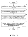
- FIG. 10 is a flow diagram showing another illustrative method for controlling the flow of fluid through a microfluidic cartridge that includes two or more flow channels.
- the flow diagram is entered at step 140 , wherein control is passed to step 144 .
- Step 144 causes flow of a fluid in a first flow channel at a first flow rate.
- Control is then passed to step 146 .
- Step 146 causes flow of a fluid in a second flow channel at a second flow rate.
- Control is then passed to step 148 .
- Step 148 increases the flow rate of the fluid in the first flow channel when the fluid in the first flow channel reaches or substantially reaches a first predetermined location.
- Control is then passed to step 150 .
- Step 150 increases the flow rate of the fluid in the second flow channel when the fluid in the second flow channel reaches or substantially reaches a second predetermined location.
- Control is then passed to step 152 , wherein the flow diagram is exited.
- FIG. 11 is a timing diagram showing an illustrative timing protocol for the illustrative microfluidic cartridge 10 of FIG. 1 .
- channel “A” corresponds to the first flow channel 12 of FIG. 1
- channel “B” corresponds to the second flow channel 14
- channel “C” corresponds to the fourth flow channel 20 .
- a blood sample is first initiated at a first blood sample flow rate 170 in channel “B”. This is continued for about twelve seconds. Then, a lyse reagent is initiated at a first lyse flow rate 172 , and at the same time the blood sample flow rate is increased to a second blood sample flow rate 174 . In this example, the blood sample flow rate is increased to help prevent a backflow of the blood sample in the second flow channel 14 .
- the first intersecting region 16 may be adapted to inject a ribbon of the blood sample between two sheathing layers of lyse reagent.
- the ribbon is stretched thinner during acceleration into the third flow channel 18 .
- the blood sample ribbon is two to three cells thick, so all of the blood cells are close to the lysing reagent, and all cells are exposed to the lysing reagent for an equal time. This “lysing on the fly” may provide more consistent results than batch lysing.
- the length of the third flow channel 18 may have a length that results in the blood sample being lysed for a desired amount of time before reaching the second intersecting region 22 .
- a sheath fluid is activated in channel “C” at a sheathing fluid flow rate 176 .
- the lyse flow rate is slightly increased to help prevent a backflow in the third flow channel 18 .
- the second intersecting region 22 may be configured to arrange the blood cells in the lysed blood sample into a single file so that they can be individually interrogated by a microfluidic cartridge reader as they pass through optical window region 26 . In the illustrative embodiment, twenty seconds is provided to achieve a consistent core flow through the fifth flow channel 24 in the region of the optical window region 26 , as shown at 180 .
- a run time period 182 having a duration of about 90 second, where the cells in the core are optically interrogated by a microfluidic cartridge reader.
- the flows in the first, second and third flow channels are terminated, and a fifteen second wait period 184 is entered.
- the wait period 184 may allow sufficient time to properly shut down the pressure sources, as well as close any valves on the microfluidic cartridge 10 and/or perform any other shut down operations. It should be recognized that this timing protocol is only given as an example, and that the particular sequence of events and timing of events will depend on the particular microfluidic cartridge design.
- FIG. 12 is a schematic top view diagram showing certain select structures of an illustrative microfluidic cartridge that includes one or more fluidic processes monitor structures.
- many microfluidic cartridges are manufactured from plastic laminates or molded parts, which can help reduce the size, cost and complexity of the microfluidic cartridge.
- manufacturing techniques may provide inexpensive parts, they are typically less dimensionally precise and repeatable, with asymmetrical dimensions and wider tolerance cross-sections.
- process variations may produce variations in fluid flows, component performance, etc., from cartridge to cartridge—which can degrade the accuracy and/or performance of any timing protocols that are developed in advance for a particular class of microfluidic cartridges.
- one or more fluidic process monitor components/structures may be fabricated along with the functional components/structures of the microfluidic cartridge.
- FIG. 12 show a microfluidic cartridge 200 that includes a separate process monitor region 202 . It is contemplated, however, that the process monitor components/structures may be dispersed among the functional components/structures of the microfluidic cartridge, if desired.
- the process monitor components/structures may include a series of flow channels, sometimes with similar or identical dimensions as the first, second, third, fourth and fifth flow channels 12 , 14 , 18 , 20 and 24 on the functional part of the microfluidic cartridge 200 .
- Wet out times of some or all of the process monitor flow channels may be measured to identify the specific wet out times for the microfluidic cartridge at hand, rather than identifying wet out times for a class of microfluidic cartridges generally.
- the timing protocol for the particular microfluidic cartridge may be more accurate.
- the some or all of the process monitor components/structures in the process monitor region 202 may be tested prior to shipment of the microfluidic cartridge 200 .
- data that is specific to the microfluidic cartridge 200 may be recorded on the microfluidic cartridge 200 .
- the data may be recorded in a machine readable format in a process-monitor data region 204 .
- the data may be recorded as a bar code printed on the microfluidic cartridge 200 .
- the data may be recorded on an optical, magnetic or RF tag that is secured to the microfluidic cartridge 200 .
- Any other sort of storage device may also be employed, including non-volatile memory and volatile memory, if desired.
- the process monitor region 202 may be removed from the microfluidic cartridge 200 along line 206 , if desired. This may be accomplished by, for example, cutting, sawing, or using any other suitable process. In some cases, a perforation may be provided along line 206 , which may help “snap off” the process monitor region 202 from the remainder of the microfluidic cartridge 200 .
- FIG. 13 is a schematic top view diagram showing a microfluidic card reader 220 for reading the illustrative microfluidic cartridge 200 of FIG. 12 .
- the microfluidic cartridge 200 is inserted into a slot or other opening in the microfluidic card reader 220 .
- the microfluidic card reader 220 may include the necessary hardware and/or software to operate the microfluidic cartridge 200 .
- the microfluidic card reader 220 may include pumps, valves, light sources and light detectors, a controller, etc.
- the controller may be adapted to implement a timing protocol for the microfluidic cartridge 200 , as discussed herein.
- the microfluidic card reader 220 may include a reader that is capable of reading the machine readable indicia recorded in the process-monitor data region 204 . Using this data, the operation of the microfluidic card reader 220 may be altered (e.g. customized) to accommodate the process variations present in the particular microfluidic cartridge 200 . For example, the start times, flow rates and/or other parameters of some timing protocols may be changed based on the process monitor data read from the process-monitor data region 204 .
- an entire timing protocol may be recorded in the process-monitor data region 204 .
- the type of card, the reagents used, the model number, the serial number, as well as other parameters may be recorded in the process-monitor data region 204 . This may help prevent errors during use, because some or all of the card characteristics may be read and used by the microfluidic card reader 220 .
- the microfluidic card reader 220 may be capable of performing some or all of the tests on the process monitor components/structures just prior to use. For example, the microfluidic card reader 220 may pump fluids through one or more flow channels in the process monitor region 202 , and then based on the results, change some of the parameters of the timing protocol that is ultimately used by the microfluidic card reader 220 during function operation of the microfluidic cartridge 200 .
- FIG. 14 is a more detailed schematic top view diagram showing the process monitor region 202 of the illustrative microfluidic cartridge 200 of FIG. 12 .
- the process monitor region 202 may include a variety of process monitor components/structures, as desired.
- the process monitor region 202 may include process monitor flow channel structures 230 , 232 and 234 , which may have the same cross-sectional dimensions, and in some cases the same overall shape, as the functional flow channels 12 , 14 and 20 on the functional part of the card.
- process monitor flow channel structures 230 , 232 and 234 are fabricated at the same time as the functional flow channels 12 , 14 and 20 , data collected from the process monitor flow channel structures 230 , 232 and 234 may be highly predictive of the performance of the functional flow channels 12 , 14 and 20 .
- process monitor components/structures may also be provided.
- a reservoir 240 may be provided.
- a copy of the second intersecting region 22 may be provided as shown at 250 , was well as a copy of the optical window 26 as shown at 260 .
- Other structures may also be provided including, for example, various flow channels 270 that extend between various lamination layers of the microfluidic cartridge 200 , one or more valves 280 , layer alignment features 290 , as well as any other suitable components/structures that may provide relevant data regarding the process/fabrication variations in the microfluidic cartridge 200 .
- FIG. 15 is a flow diagram showing an illustrative method for characterizing and operating a microfluidic cartridge.
- the flow diagram is entered at step 300 , and control is passed to step 302 .
- Step 302 provides one or more test elements on a microfluidic cartridge, wherein the one or more test elements are fabricated along with a functional part of the microfluidic cartridge.
- Control is then passed to step 304 .
- Step 304 performs one or more tests using the one or more test elements to generate characterization data for at least part of the functional part of the microfluidic cartridge.
- Control is then passed to step 306 .
- Step 306 operates the microfluidic cartridge using a microfluidic cartridge reader or the like, wherein one or more operating parameters of the microfluidic cartridge reader are changed in response to the characterization data. Control is then passed to step 308 , wherein the flow diagram is exited.
- FIG. 16 is a flow diagram showing another illustrative method for operating a microfluidic cartridge.
- the flow diagram is entered at step 320 , and control is passed to step 322 .
- Step 322 receives a microfluidic cartridge having a fluidic circuit.
- Control is then passed to step 324 .
- Step 324 reads one or more indicia from the microfluidic cartridge, wherein the one or more indicia include one or more performance characteristics of at least part of the microfluidic cartridge. At least some of the one or more performance characteristics are determined by making one or more measurements on one or more test elements that are fabricated along with the microfluidic cartridge.
- Control is then passed to step 326 .
- Step 326 changes one or more operating parameters of a microfluidic cartridge reader or the like in response to the information read. Control is then passed to step 328 . Step 328 operates the microfluidic cartridge reader or the like using the changed operating parameters. Control is then passed to step 330 , wherein the flow diagram is exited.
- FIG. 17 is a flow diagram showing yet another illustrative method for characterizing a microfluidic cartridge.
- the flow diagram is entered at step 340 , and control is passed to step 342 .
- Step 342 performs at least some of the steps of fabricating the fluidic circuit device, wherein the fluidic circuit device includes one or more test elements.
- Control is then passed to step 344 .
- Step 344 performs one or more tests on at least one of the test elements. If the test is a pass/fail type test, control is passed to step 346 , wherein it is determine if the test passed or failed. If the test passed, and additional fabrication steps are required to complete the fluidic circuit device, control is passed back to step 342 . If the test failed, control is passed to step 348 , wherein the microfluidic cartridge is rejected. Control is then passed to step 350 , wherein the flow diagram is exited.
- Step 344 determines whether the test was not a pass/fail type test. If the test was not a pass/fail type test, at least some of the test results are recorded, as shown at step 352 . Control is then passed to step 354 . Step 354 determines whether the fluidic cartridge device is completely fabricated. If the fluidic cartridge device is not completely fabricated, control is passed back to step 342 . However, if the fluidic cartridge device is completely fabricated, control is passed to step 350 , wherein the control diagram is exited.
- FIG. 18 is a flow diagram showing an illustrative method for binning microfluidic cartridges.
- the flow diagram is entered at step 360 , wherein control is passed to step 362 .
- Step 362 performs at least some of the steps of fabricating a fluidic circuit device, wherein the fluidic circuit device includes one or more test elements.
- Control is then passed to step 364 .
- Step 364 performs one or more tests on at least one of the test elements.
- Control is then passed to step 366 .
- Step 366 bins the microfluidic circuit device into one of two or more bins depending on the test results.
- Control is then passed to step 370 , wherein the flow diagram is exited.
Abstract
Description
Claims (28)
Priority Applications (10)
| Application Number | Priority Date | Filing Date | Title |
|---|---|---|---|
| US10/932,662 US8329118B2 (en) | 2004-09-02 | 2004-09-02 | Method and apparatus for determining one or more operating parameters for a microfluidic circuit |
| EP20110190039 EP2425895B1 (en) | 2004-09-02 | 2005-09-02 | Method and apparatus for determining one or more operating parameters for a microfluidic circuit |
| PCT/US2005/031340 WO2006135410A2 (en) | 2004-09-02 | 2005-09-02 | Method and apparatus for determining one or more operating parameters for a microfluidic circuit |
| JP2007530403A JP2008511842A (en) | 2004-09-02 | 2005-09-02 | Method and apparatus for determining one or more operating parameters of a microfluidic circuit |
| EP14181880.7A EP2805772B1 (en) | 2004-09-02 | 2005-09-02 | Method and apparatus for determining one or more operating parameters for a microfluidic circuit |
| EP20050857929 EP1784261B1 (en) | 2004-09-02 | 2005-09-02 | Method and apparatus for determining one or more operating parameters for a microfluidic circuit |
| CN2005800379695A CN101052469B (en) | 2004-09-02 | 2005-09-02 | Method and apparatus for determining one or more operating parameters for a microfluidic circuit |
| CN201110378729.9A CN102513168B (en) | 2004-09-02 | 2005-09-02 | Method and apparatus for determining one or more operating parameters for a microfluidic circuit |
| US11/306,508 US20060263888A1 (en) | 2000-06-02 | 2005-12-30 | Differential white blood count on a disposable card |
| US11/618,502 US7553453B2 (en) | 2000-06-02 | 2006-12-29 | Assay implementation in a microfluidic format |
Applications Claiming Priority (1)
| Application Number | Priority Date | Filing Date | Title |
|---|---|---|---|
| US10/932,662 US8329118B2 (en) | 2004-09-02 | 2004-09-02 | Method and apparatus for determining one or more operating parameters for a microfluidic circuit |
Related Parent Applications (1)
| Application Number | Title | Priority Date | Filing Date |
|---|---|---|---|
| US10/899,607 Continuation-In-Part US7242474B2 (en) | 2000-06-02 | 2004-07-27 | Cytometer having fluid core stream position control |
Related Child Applications (1)
| Application Number | Title | Priority Date | Filing Date |
|---|---|---|---|
| US11/306,508 Continuation-In-Part US20060263888A1 (en) | 2000-06-02 | 2005-12-30 | Differential white blood count on a disposable card |
Publications (2)
| Publication Number | Publication Date |
|---|---|
| US20060046300A1 US20060046300A1 (en) | 2006-03-02 |
| US8329118B2 true US8329118B2 (en) | 2012-12-11 |
Family
ID=35943771
Family Applications (1)
| Application Number | Title | Priority Date | Filing Date |
|---|---|---|---|
| US10/932,662 Active 2028-02-12 US8329118B2 (en) | 2000-06-02 | 2004-09-02 | Method and apparatus for determining one or more operating parameters for a microfluidic circuit |
Country Status (5)
| Country | Link |
|---|---|
| US (1) | US8329118B2 (en) |
| EP (3) | EP1784261B1 (en) |
| JP (1) | JP2008511842A (en) |
| CN (2) | CN102513168B (en) |
| WO (1) | WO2006135410A2 (en) |
Cited By (10)
| Publication number | Priority date | Publication date | Assignee | Title |
|---|---|---|---|---|
| US20130061936A1 (en) * | 2010-05-21 | 2013-03-14 | Hewlett-Packard Development Company, L.P. | Generating fluid flow in a fluidic network |
| US8802445B2 (en) | 2007-05-04 | 2014-08-12 | Opko Diagnostics, Llc | Fluidic connectors and microfluidic systems |
| US9366606B1 (en) | 2015-08-27 | 2016-06-14 | Ativa Medical Corporation | Fluid processing micro-feature devices and methods |
| US9395050B2 (en) | 2010-05-21 | 2016-07-19 | Hewlett-Packard Development Company, L.P. | Microfluidic systems and networks |
| US9827563B2 (en) | 2009-02-02 | 2017-11-28 | Opko Diagnostics, Llc | Fluidic systems and methods for analyses |
| US9963739B2 (en) | 2010-05-21 | 2018-05-08 | Hewlett-Packard Development Company, L.P. | Polymerase chain reaction systems |
| US10173435B2 (en) | 2010-05-21 | 2019-01-08 | Hewlett-Packard Development Company, L.P. | Fluid ejection device including recirculation system |
| US10612070B2 (en) | 2015-08-27 | 2020-04-07 | Ativa Medical Corporation | Fluid holding and dispensing micro-feature |
| US10672503B2 (en) | 2012-03-05 | 2020-06-02 | Opko Diagnostics, Llc | Methods and apparatuses for conducting analyses |
| US11071982B2 (en) | 2015-08-27 | 2021-07-27 | Ativa Medical Corporation | Fluid holding and dispensing micro-feature |
Families Citing this family (22)
| Publication number | Priority date | Publication date | Assignee | Title |
|---|---|---|---|---|
| JP5077227B2 (en) * | 2006-03-29 | 2012-11-21 | コニカミノルタエムジー株式会社 | Reaction method and analysis device in flow path of microchip |
| US9591994B2 (en) | 2007-01-23 | 2017-03-14 | Dtherapeutics, Llc | Systems and methods to obtain a myocardial mass index indicative of an at-risk myocardial region |
| WO2008091568A2 (en) | 2007-01-23 | 2008-07-31 | Dtherapeutics, Llc | Applications of scaling laws of tree structures |
| CN103143404B (en) * | 2007-05-03 | 2015-05-13 | 科隆迪亚戈有限公司 | Assays |
| US20110137596A1 (en) * | 2008-04-30 | 2011-06-09 | The Board Of Regents Of The University Of Texas System | Quality control method and micro/nano-channeled devices |
| US10066977B2 (en) | 2009-01-26 | 2018-09-04 | Canon U.S. Life Sciences, Inc. | Microfluidic flow monitoring |
| US9404152B2 (en) | 2009-01-26 | 2016-08-02 | Canon U.S. Life Sciences, Inc. | Microfluidic flow monitoring |
| JP5340760B2 (en) * | 2009-02-12 | 2013-11-13 | 倉敷紡績株式会社 | Fluid control method and fluid control apparatus |
| TW201116223A (en) * | 2009-08-13 | 2011-05-16 | Code Footwear Llc | Reconfigurable shoes and apparel and docking assembly therefor |
| US9000769B2 (en) | 2009-11-23 | 2015-04-07 | Proxim Diagnostics | Controlled electrochemical activation of carbon-based electrodes |
| US8580569B2 (en) | 2010-04-16 | 2013-11-12 | Opko Diagnostics, Llc | Feedback control in microfluidic systems |
| JP5622938B2 (en) * | 2010-09-09 | 2014-11-12 | フラウンホッファー−ゲゼルシャフト ツァ フェルダールング デァ アンゲヴァンテン フォアシュンク エー.ファオ | Microfluidic device, microfluidic injection system, and method of microfluidic flow measurement and injection |
| JP5782742B2 (en) * | 2011-02-22 | 2015-09-24 | 株式会社島津製作所 | Analysis system |
| US9638663B2 (en) * | 2011-07-25 | 2017-05-02 | Proxim Diagnostics Corporation | Cartridge for diagnostic testing |
| US10610861B2 (en) | 2012-12-17 | 2020-04-07 | Accellix Ltd. | Systems, compositions and methods for detecting a biological condition |
| EP3508848B1 (en) | 2012-12-17 | 2022-10-05 | Accellix Ltd | Systems and methods for determining a chemical state |
| US9759722B2 (en) | 2012-12-17 | 2017-09-12 | Leukodx Ltd. | Systems and methods for determining a chemical state |
| US9925319B2 (en) * | 2015-04-02 | 2018-03-27 | Purdue Research Foundation | Methods and apparatuses for impedance-based gas detection for microfluidic systems |
| JP6102980B2 (en) * | 2015-05-18 | 2017-03-29 | 株式会社島津製作所 | Analysis system |
| US10207266B2 (en) * | 2015-09-29 | 2019-02-19 | Foxconn Interconnect Technology Limited | Microfluidic device for detecting cells of blood |
| JP6896104B2 (en) * | 2018-07-27 | 2021-06-30 | ゼプト ライフ テクノロジー, エルエルシーZepto Life Technology, Llc | Biomarker detection system and method by GMR |
| CN110927085A (en) * | 2019-12-13 | 2020-03-27 | 循证医疗科技(杭州)有限公司 | Blood sample detection system |
Citations (132)
| Publication number | Priority date | Publication date | Assignee | Title |
|---|---|---|---|---|
| US3822095A (en) | 1972-08-14 | 1974-07-02 | Block Engineering | System for differentiating particles |
| US3928094A (en) | 1975-01-16 | 1975-12-23 | Fairchild Camera Instr Co | Method of aligning a wafer beneath a mask and system therefor and wafer having a unique alignment pattern |
| US3976862A (en) | 1975-03-18 | 1976-08-24 | Block Engineering, Inc. | Flow stream processor |
| US4284412A (en) | 1979-07-13 | 1981-08-18 | Ortho Diagnostics, Inc. | Method and apparatus for automated identification and enumeration of specified blood cell subclasses |
| US4478076A (en) | 1982-09-30 | 1984-10-23 | Honeywell Inc. | Flow sensor |
| US4478077A (en) | 1982-09-30 | 1984-10-23 | Honeywell Inc. | Flow sensor |
| US4501144A (en) | 1982-09-30 | 1985-02-26 | Honeywell Inc. | Flow sensor |
| US4599000A (en) | 1982-02-19 | 1986-07-08 | Canon Kabushiki Kaisha | Position detection signal processing apparatus |
| US4651564A (en) | 1982-09-30 | 1987-03-24 | Honeywell Inc. | Semiconductor device |
| US4683159A (en) | 1982-09-30 | 1987-07-28 | Honeywell Inc. | Semiconductor device structure and processing |
| US4695034A (en) | 1984-11-27 | 1987-09-22 | Stec Inc. | Fluid control device |
| US4704033A (en) | 1986-03-06 | 1987-11-03 | Micronix Corporation | Multiple wavelength linear zone plate alignment apparatus and method |
| US4745279A (en) | 1986-01-02 | 1988-05-17 | American Hospital Supply Corporation | Hematocrit measuring apparatus |
| US4818263A (en) | 1987-06-11 | 1989-04-04 | Tektronix, Inc. | Method and apparatus for precisely positioning microlenses on optical fibers |
| US4874949A (en) | 1987-09-14 | 1989-10-17 | Vanderbilt University | Method of measuring lung vascular function and transcapillary transport by the use of nonradioactive markers |
| US4911616A (en) | 1988-01-19 | 1990-03-27 | Laumann Jr Carl W | Micro miniature implantable pump |
| US4932989A (en) | 1989-04-05 | 1990-06-12 | At&T Bell Laboratories | Method and apparatus for fabricating microlenses on optical fibers |
| US4980292A (en) | 1984-10-01 | 1990-12-25 | Baxter International Inc. | Tablet dispensing |
| US5017497A (en) | 1986-04-21 | 1991-05-21 | Sequoia-Turner Corporation | Particle discriminator and method |
| US5050429A (en) | 1990-02-22 | 1991-09-24 | Yamatake-Honeywell Co., Ltd. | Microbridge flow sensor |
| US5078581A (en) | 1989-08-07 | 1992-01-07 | International Business Machines Corporation | Cascade compressor |
| US5082242A (en) | 1989-12-27 | 1992-01-21 | Ulrich Bonne | Electronic microvalve apparatus and fabrication |
| US5085562A (en) | 1989-04-11 | 1992-02-04 | Westonbridge International Limited | Micropump having a constant output |
| US5096388A (en) | 1990-03-22 | 1992-03-17 | The Charles Stark Draper Laboratory, Inc. | Microfabricated pump |
| US5108623A (en) | 1990-11-19 | 1992-04-28 | Gould Inc. | Moving web filter assembly |
| US5129794A (en) | 1990-10-30 | 1992-07-14 | Hewlett-Packard Company | Pump apparatus |
| US5171132A (en) | 1989-12-27 | 1992-12-15 | Seiko Epson Corporation | Two-valve thin plate micropump |
| US5176358A (en) | 1991-08-08 | 1993-01-05 | Honeywell Inc. | Microstructure gas valve control |
| EP0269076B1 (en) | 1986-11-27 | 1993-01-13 | Nokia (Deutschland) GmbH | Positioning device |
| US5185641A (en) | 1990-11-03 | 1993-02-09 | Horiba, Ltd. | Apparatus for simultaneously measuring large and small particle size distribution |
| US5194909A (en) | 1990-12-04 | 1993-03-16 | Tycko Daniel H | Apparatus and method for measuring volume and hemoglobin concentration of red blood cells |
| US5219278A (en) | 1989-11-10 | 1993-06-15 | Westonbridge International, Ltd. | Micropump with improved priming |
| US5224843A (en) | 1989-06-14 | 1993-07-06 | Westonbridge International Ltd. | Two valve micropump with improved outlet |
| US5244537A (en) | 1989-12-27 | 1993-09-14 | Honeywell, Inc. | Fabrication of an electronic microvalve apparatus |
| US5405510A (en) | 1992-05-18 | 1995-04-11 | Ppg Industries, Inc. | Portable analyte measuring system for multiple fluid samples |
| US5413764A (en) | 1989-04-08 | 1995-05-09 | Boehringer Mannheim Gmbh | Test carrier analysis system |
| US5441597A (en) | 1992-12-01 | 1995-08-15 | Honeywell Inc. | Microstructure gas valve control forming method |
| US5452878A (en) | 1991-06-18 | 1995-09-26 | Danfoss A/S | Miniature actuating device |
| US5457526A (en) | 1992-08-10 | 1995-10-10 | Toa Medical Electronics Co., Ltd. | Apparatus for analyzing particles in fluid samples |
| US5510267A (en) | 1989-05-15 | 1996-04-23 | Abbott Laboratories | Flow cytometry lytic agent and method enabling 5-part leukocyte differential count |
| US5528045A (en) | 1995-04-06 | 1996-06-18 | Becton Dickinson And Company | Particle analyzer with spatially split wavelength filter |
| US5570193A (en) | 1992-07-02 | 1996-10-29 | Indigo N.V. | Concentration detector for colored toner |
| US5601080A (en) | 1994-12-28 | 1997-02-11 | Coretech Medical Technologies Corporation | Spectrophotometric blood analysis |
| US5616501A (en) | 1993-05-14 | 1997-04-01 | Coulter Corporation | Reticulocyte analyzing method and apparatus utilizing light scatter techniques |
| US5620657A (en) | 1989-11-27 | 1997-04-15 | Behringwerke Ag | Device and method for completing a fluidic circuit |
| US5633724A (en) | 1995-08-29 | 1997-05-27 | Hewlett-Packard Company | Evanescent scanning of biochemical array |
| US5683159A (en) | 1997-01-03 | 1997-11-04 | Johnson; Greg P. | Hardware mounting rail |
| US5716852A (en) | 1996-03-29 | 1998-02-10 | University Of Washington | Microfabricated diffusion-based chemical sensor |
| US5717631A (en) | 1995-07-21 | 1998-02-10 | Carnegie Mellon University | Microelectromechanical structure and process of making same |
| US5726751A (en) | 1995-09-27 | 1998-03-10 | University Of Washington | Silicon microchannel optical flow cytometer |
| US5757476A (en) | 1995-12-19 | 1998-05-26 | Toa Medical Electronics Co., Ltd. | Analyzer for analyzing particle components in urine with flow cytometry |
| US5760900A (en) | 1989-03-18 | 1998-06-02 | Canon Kabushiki Kaisha | Method and apparatus for optically measuring specimen |
| US5793485A (en) | 1995-03-20 | 1998-08-11 | Sandia Corporation | Resonant-cavity apparatus for cytometry or particle analysis |
| US5799030A (en) | 1996-07-26 | 1998-08-25 | Honeywell Inc. | Semiconductor device with a laser and a photodetector in a common container |
| US5822170A (en) | 1997-10-09 | 1998-10-13 | Honeywell Inc. | Hydrophobic coating for reducing humidity effect in electrostatic actuators |
| US5836750A (en) | 1997-10-09 | 1998-11-17 | Honeywell Inc. | Electrostatically actuated mesopump having a plurality of elementary cells |
| US5837547A (en) | 1995-12-27 | 1998-11-17 | Caribbean Microparticles Corporation | Flow cytometer calibration method |
| US5839807A (en) | 1995-11-09 | 1998-11-24 | C.R.F. Societa Consortile Per Azioni | Device with micro-filters for selecting colors and images |
| US5863502A (en) | 1996-01-24 | 1999-01-26 | Sarnoff Corporation | Parallel reaction cassette and associated devices |
| US5874990A (en) | 1996-04-01 | 1999-02-23 | Star Micronics, Inc. | Supervisory camera system |
| US5880474A (en) | 1997-08-29 | 1999-03-09 | Becton Dickinson And Company | Multi-illumination-source flow particle analyzer with inter-location emissions crosstalk cancelation |
| US5893722A (en) | 1996-06-28 | 1999-04-13 | Honeywell Inc. | Fabrication of vertical cavity surface emitting laser with current confinement |
| US5901939A (en) | 1997-10-09 | 1999-05-11 | Honeywell Inc. | Buckled actuator with enhanced restoring force |
| US5922210A (en) | 1995-06-16 | 1999-07-13 | University Of Washington | Tangential flow planar microfabricated fluid filter and method of using thereof |
| US5932100A (en) | 1995-06-16 | 1999-08-03 | University Of Washington | Microfabricated differential extraction device and method |
| US5948684A (en) | 1997-03-31 | 1999-09-07 | University Of Washington | Simultaneous analyte determination and reference balancing in reference T-sensor devices |
| US5971158A (en) | 1996-06-14 | 1999-10-26 | University Of Washington | Absorption-enhanced differential extraction device |
| US5974867A (en) | 1997-06-13 | 1999-11-02 | University Of Washington | Method for determining concentration of a laminar sample stream |
| US6007775A (en) | 1997-09-26 | 1999-12-28 | University Of Washington | Multiple analyte diffusion based chemical sensor |
| JP2000056228A (en) | 1998-08-04 | 2000-02-25 | Carl Zeiss Jena Gmbh | System for detection by wavelengths to be used for laser scanning microscope, and image recording method |
| US6032689A (en) | 1998-10-30 | 2000-03-07 | Industrial Technology Research Institute | Integrated flow controller module |
| US6054335A (en) | 1997-12-12 | 2000-04-25 | Xerox Corporation | Fabrication of scanning III-V compound light emitters integrated with Si-based actuators |
| US6082185A (en) | 1997-07-25 | 2000-07-04 | Research International, Inc. | Disposable fluidic circuit cards |
| US6091502A (en) | 1998-12-23 | 2000-07-18 | Micronics, Inc. | Device and method for performing spectral measurements in flow cells with spatial resolution |
| US6091537A (en) | 1998-12-11 | 2000-07-18 | Xerox Corporation | Electro-actuated microlens assemblies |
| US6091197A (en) | 1998-06-12 | 2000-07-18 | Xerox Corporation | Full color tunable resonant cavity organic light emitting diode |
| US6094293A (en) | 1998-07-23 | 2000-07-25 | Mitsubishi Denki Kabushiki Kaisha | Optical switching apparatus for use in an optical communication system |
| US6097485A (en) | 1999-03-08 | 2000-08-01 | Integrated Waveguides, Inc. | Microchip optical transport technology for use in a personal flow cytometer |
| US6097859A (en) | 1998-02-12 | 2000-08-01 | The Regents Of The University Of California | Multi-wavelength cross-connect optical switch |
| US6106245A (en) | 1997-10-09 | 2000-08-22 | Honeywell | Low cost, high pumping rate electrostatically actuated mesopump |
| US6109889A (en) | 1995-12-13 | 2000-08-29 | Hahn-Schickard-Gesellschaft Fur Angewandte Forschung E.V. | Fluid pump |
| US6116756A (en) | 1997-12-12 | 2000-09-12 | Xerox Corporation | Monolithic scanning light emitting devices |
| US6124663A (en) | 1996-12-16 | 2000-09-26 | The Boeing Company | Fiber optic connector having a microelectromechanical positioning apparatus and an associated fabrication method |
| US6139800A (en) | 1997-06-23 | 2000-10-31 | Luminex Corporation | Interlaced lasers for multiple fluorescence measurement |
| US6179586B1 (en) | 1999-09-15 | 2001-01-30 | Honeywell International Inc. | Dual diaphragm, single chamber mesopump |
| US6184607B1 (en) | 1998-12-29 | 2001-02-06 | Honeywell International Inc. | Driving strategy for non-parallel arrays of electrostatic actuators sharing a common electrode |
| US6215221B1 (en) | 1998-12-29 | 2001-04-10 | Honeywell International Inc. | Electrostatic/pneumatic actuators for active surfaces |
| US6237619B1 (en) | 1996-10-03 | 2001-05-29 | Westonbridge International Limited | Micro-machined device for fluids and method of manufacture |
| US6240944B1 (en) | 1999-09-23 | 2001-06-05 | Honeywell International Inc. | Addressable valve arrays for proportional pressure or flow control |
| US6249341B1 (en) | 1999-01-25 | 2001-06-19 | Amnis Corporation | Imaging and analyzing parameters of small moving objects such as cells |
| US6281975B1 (en) | 2000-03-07 | 2001-08-28 | Eldex Laboratories, Inc. | Capillary flow cell with bulbous ends |
| EP0694784B1 (en) | 1994-07-28 | 2002-02-27 | Hitachi, Ltd. | Liquid sampling apparatus |
| DE10122321A1 (en) | 2000-05-09 | 2002-04-11 | Busch Dieter & Co Prueftech | Alignment of two machine parts, especially axles, is determined using an opto-electronic measurement instrument provided with two separately controlled devices for emitting a laser beam and with one laser light receiver |
| US6382228B1 (en) | 2000-08-02 | 2002-05-07 | Honeywell International Inc. | Fluid driving system for flow cytometry |
| US6408884B1 (en) * | 1999-12-15 | 2002-06-25 | University Of Washington | Magnetically actuated fluid handling devices for microfluidic applications |
| US6409832B2 (en) | 2000-03-31 | 2002-06-25 | Micronics, Inc. | Protein crystallization in microfluidic structures |
| US20020108097A1 (en) | 2000-06-27 | 2002-08-08 | Fluidigm Corporation | Object oriented microfluidic design method and system |
| US20020108096A1 (en) | 2000-06-27 | 2002-08-08 | Michael Lee | Microfluidic design automation method and system |
| US20020110926A1 (en) | 2001-01-16 | 2002-08-15 | Caliper Technologies Corp. | Emulator device |
| US6440725B1 (en) | 1997-12-24 | 2002-08-27 | Cepheid | Integrated fluid manipulation cartridge |
| US20020149766A1 (en) | 2001-04-03 | 2002-10-17 | Ronald Bardell | Split focusing cytometer |
| US6488896B2 (en) | 2000-03-14 | 2002-12-03 | Micronics, Inc. | Microfluidic analysis cartridge |
| US20020185184A1 (en) | 2001-06-07 | 2002-12-12 | Nanostream, Inc. | Microfluidic synthesis devices and methods |
| US20030057968A1 (en) | 2001-09-26 | 2003-03-27 | Wang Da Yu | Liquid property sensor |
| US6549275B1 (en) | 2000-08-02 | 2003-04-15 | Honeywell International Inc. | Optical detection system for flow cytometry |
| US6557427B2 (en) | 2000-05-24 | 2003-05-06 | Micronics, Inc. | Capillaries for fluid movement within microfluidic channels |
| US6581899B2 (en) | 2000-06-23 | 2003-06-24 | Micronics, Inc. | Valve for use in microfluidic structures |
| US6594009B2 (en) | 2001-02-27 | 2003-07-15 | Honeywell International Inc. | Flow cytometer and ultraviolet light disinfecting systems |
| US6597438B1 (en) | 2000-08-02 | 2003-07-22 | Honeywell International Inc. | Portable flow cytometry |
| US20030142291A1 (en) | 2000-08-02 | 2003-07-31 | Aravind Padmanabhan | Portable scattering and fluorescence cytometer |
| US20030148535A1 (en) | 2000-03-07 | 2003-08-07 | Bruno Colin | Method for producing a test sample card |
| US6632619B1 (en) * | 1997-05-16 | 2003-10-14 | The Governors Of The University Of Alberta | Microfluidic system and methods of use |
| EP1359419A1 (en) | 2002-05-01 | 2003-11-05 | Lifescan, Inc. | Device and method for analyte concentration determination |
| US6664104B2 (en) | 1999-06-25 | 2003-12-16 | Cepheid | Device incorporating a microfluidic chip for separating analyte from a sample |
| US6700130B2 (en) | 2001-06-29 | 2004-03-02 | Honeywell International Inc. | Optical detection system for flow cytometry |
| US20040065143A1 (en) | 2002-10-03 | 2004-04-08 | Husher Frederick K. | Apparatus and method for analyzing a liquid in a capillary tube of a hematology instrument |
| US20040072278A1 (en) | 2002-04-01 | 2004-04-15 | Fluidigm Corporation | Microfluidic particle-analysis systems |
| US6742661B1 (en) | 2001-04-03 | 2004-06-01 | Micronics, Inc. | Well-plate microfluidics |
| US6743399B1 (en) | 1999-10-08 | 2004-06-01 | Micronics, Inc. | Pumpless microfluidics |
| US20040109386A1 (en) | 2002-11-18 | 2004-06-10 | Gold Kenneth S. | Particle analyzer with specimen tube in-line mixer and fluid detector |
| WO2004059316A1 (en) | 2002-12-17 | 2004-07-15 | The Regents Of The University Of Michigan | Device for the determination of blood clotting by capacitance or resistance |
| US20040154933A1 (en) | 2003-02-11 | 2004-08-12 | Instrumentation Laboratory Company | Polymeric membranes for use in electrochemical sensors |
| JP2004257756A (en) | 2003-02-24 | 2004-09-16 | Nippon Koden Corp | Flow cell positioning method and flow cytometer capable of adjusting position of flow cell |
| US20040233424A1 (en) | 2003-05-21 | 2004-11-25 | National Cheng Kung University | Chip-based microfluidic particle detector with three dimensional focusing mechanisms |
| US20050105077A1 (en) | 2000-08-02 | 2005-05-19 | Aravind Padmanabhan | Miniaturized cytometer for detecting multiple species in a sample |
| EP1001326B1 (en) | 1998-05-29 | 2005-08-31 | Fujikin Inc. | Gas supply equipment with pressure type flow rate control device |
| WO2005108963A1 (en) | 2004-05-06 | 2005-11-17 | Nanyang Technological University | Microfluidic cell sorter system |
| WO2005090983A3 (en) | 2004-02-27 | 2005-11-17 | Univ Texas | Membrane assay system including preloaded particles |
| WO2005114144A1 (en) | 2004-05-14 | 2005-12-01 | Honeywell International, Inc. | Portable sample analyzer cartridge |
| EP1134548B1 (en) | 2000-03-10 | 2006-06-14 | HAMAR LASER INSTRUMENTS, Inc. | Laser alignment system with plural lasers for impingement on a single target |
| WO2005114142A3 (en) | 2004-05-14 | 2006-08-17 | Honeywell Int Inc | Portable sample analyzer with removable cartridge |
| US7143785B2 (en) * | 2002-09-25 | 2006-12-05 | California Institute Of Technology | Microfluidic large scale integration |
Family Cites Families (14)
| Publication number | Priority date | Publication date | Assignee | Title |
|---|---|---|---|---|
| DE3650409T2 (en) * | 1985-11-07 | 1996-02-29 | Bifok Ab | Sample delivery system for non-segmented continuous flow analysis. |
| JP2948069B2 (en) * | 1993-09-20 | 1999-09-13 | 株式会社日立製作所 | Chemical analyzer |
| US6399023B1 (en) * | 1996-04-16 | 2002-06-04 | Caliper Technologies Corp. | Analytical system and method |
| CA2264389A1 (en) * | 1996-09-04 | 1998-03-12 | Technical University Of Denmark | A micro flow system for particle separation and analysis |
| WO1999064836A1 (en) * | 1998-06-08 | 1999-12-16 | Caliper Technologies Corp. | Microfluidic devices, systems and methods for performing integrated reactions and separations |
| EP1125129A1 (en) * | 1998-10-13 | 2001-08-22 | Biomicro Systems, Inc. | Fluid circuit components based upon passive fluid dynamics |
| US6416642B1 (en) * | 1999-01-21 | 2002-07-09 | Caliper Technologies Corp. | Method and apparatus for continuous liquid flow in microscale channels using pressure injection, wicking, and electrokinetic injection |
| WO2001077683A1 (en) * | 2000-04-06 | 2001-10-18 | Caliper Technologies Corp. | Methods and devices for achieving long incubation times in high-throughput systems |
| US6970245B2 (en) * | 2000-08-02 | 2005-11-29 | Honeywell International Inc. | Optical alignment detection system |
| US20020098122A1 (en) * | 2001-01-22 | 2002-07-25 | Angad Singh | Active disposable microfluidic system with externally actuated micropump |
| JP2003004752A (en) * | 2001-06-15 | 2003-01-08 | Minolta Co Ltd | Microchip and inspection apparatus using the same |
| WO2003000417A2 (en) * | 2001-06-20 | 2003-01-03 | Cytonome, Inc. | Microfluidic system including a virtual wall fluid interface port for interfacing fluids with the microfluidic system |
| US7524462B2 (en) * | 2002-03-29 | 2009-04-28 | Agilent Technologies, Inc. | Capillary flow for a heterogenous assay in a micro-channel environment |
| EP1746158A4 (en) * | 2004-05-07 | 2009-11-25 | Konica Minolta Med & Graphic | Micro-reactor for testing, genetic testing apparatus, and genetic testing method |
-
2004
- 2004-09-02 US US10/932,662 patent/US8329118B2/en active Active
-
2005
- 2005-09-02 CN CN201110378729.9A patent/CN102513168B/en not_active Expired - Fee Related
- 2005-09-02 EP EP20050857929 patent/EP1784261B1/en not_active Expired - Fee Related
- 2005-09-02 CN CN2005800379695A patent/CN101052469B/en active Active
- 2005-09-02 EP EP20110190039 patent/EP2425895B1/en not_active Expired - Fee Related
- 2005-09-02 EP EP14181880.7A patent/EP2805772B1/en active Active
- 2005-09-02 WO PCT/US2005/031340 patent/WO2006135410A2/en active Application Filing
- 2005-09-02 JP JP2007530403A patent/JP2008511842A/en active Pending
Patent Citations (138)
| Publication number | Priority date | Publication date | Assignee | Title |
|---|---|---|---|---|
| US3822095A (en) | 1972-08-14 | 1974-07-02 | Block Engineering | System for differentiating particles |
| US3928094A (en) | 1975-01-16 | 1975-12-23 | Fairchild Camera Instr Co | Method of aligning a wafer beneath a mask and system therefor and wafer having a unique alignment pattern |
| US3976862A (en) | 1975-03-18 | 1976-08-24 | Block Engineering, Inc. | Flow stream processor |
| US4284412A (en) | 1979-07-13 | 1981-08-18 | Ortho Diagnostics, Inc. | Method and apparatus for automated identification and enumeration of specified blood cell subclasses |
| US4599000A (en) | 1982-02-19 | 1986-07-08 | Canon Kabushiki Kaisha | Position detection signal processing apparatus |
| US4651564A (en) | 1982-09-30 | 1987-03-24 | Honeywell Inc. | Semiconductor device |
| US4478076A (en) | 1982-09-30 | 1984-10-23 | Honeywell Inc. | Flow sensor |
| US4478077A (en) | 1982-09-30 | 1984-10-23 | Honeywell Inc. | Flow sensor |
| US4683159A (en) | 1982-09-30 | 1987-07-28 | Honeywell Inc. | Semiconductor device structure and processing |
| US4501144A (en) | 1982-09-30 | 1985-02-26 | Honeywell Inc. | Flow sensor |
| US4980292A (en) | 1984-10-01 | 1990-12-25 | Baxter International Inc. | Tablet dispensing |
| US4695034A (en) | 1984-11-27 | 1987-09-22 | Stec Inc. | Fluid control device |
| US4745279A (en) | 1986-01-02 | 1988-05-17 | American Hospital Supply Corporation | Hematocrit measuring apparatus |
| US4704033A (en) | 1986-03-06 | 1987-11-03 | Micronix Corporation | Multiple wavelength linear zone plate alignment apparatus and method |
| US5017497A (en) | 1986-04-21 | 1991-05-21 | Sequoia-Turner Corporation | Particle discriminator and method |
| EP0269076B1 (en) | 1986-11-27 | 1993-01-13 | Nokia (Deutschland) GmbH | Positioning device |
| US4818263A (en) | 1987-06-11 | 1989-04-04 | Tektronix, Inc. | Method and apparatus for precisely positioning microlenses on optical fibers |
| US4874949A (en) | 1987-09-14 | 1989-10-17 | Vanderbilt University | Method of measuring lung vascular function and transcapillary transport by the use of nonradioactive markers |
| US4911616A (en) | 1988-01-19 | 1990-03-27 | Laumann Jr Carl W | Micro miniature implantable pump |
| US5760900A (en) | 1989-03-18 | 1998-06-02 | Canon Kabushiki Kaisha | Method and apparatus for optically measuring specimen |
| US4932989A (en) | 1989-04-05 | 1990-06-12 | At&T Bell Laboratories | Method and apparatus for fabricating microlenses on optical fibers |
| US5413764A (en) | 1989-04-08 | 1995-05-09 | Boehringer Mannheim Gmbh | Test carrier analysis system |
| US5085562A (en) | 1989-04-11 | 1992-02-04 | Westonbridge International Limited | Micropump having a constant output |
| US5510267A (en) | 1989-05-15 | 1996-04-23 | Abbott Laboratories | Flow cytometry lytic agent and method enabling 5-part leukocyte differential count |
| US5224843A (en) | 1989-06-14 | 1993-07-06 | Westonbridge International Ltd. | Two valve micropump with improved outlet |
| US5078581A (en) | 1989-08-07 | 1992-01-07 | International Business Machines Corporation | Cascade compressor |
| US5219278A (en) | 1989-11-10 | 1993-06-15 | Westonbridge International, Ltd. | Micropump with improved priming |
| US5620657A (en) | 1989-11-27 | 1997-04-15 | Behringwerke Ag | Device and method for completing a fluidic circuit |
| US5171132A (en) | 1989-12-27 | 1992-12-15 | Seiko Epson Corporation | Two-valve thin plate micropump |
| US5082242A (en) | 1989-12-27 | 1992-01-21 | Ulrich Bonne | Electronic microvalve apparatus and fabrication |
| US5244537A (en) | 1989-12-27 | 1993-09-14 | Honeywell, Inc. | Fabrication of an electronic microvalve apparatus |
| US5050429A (en) | 1990-02-22 | 1991-09-24 | Yamatake-Honeywell Co., Ltd. | Microbridge flow sensor |
| US5096388A (en) | 1990-03-22 | 1992-03-17 | The Charles Stark Draper Laboratory, Inc. | Microfabricated pump |
| US5129794A (en) | 1990-10-30 | 1992-07-14 | Hewlett-Packard Company | Pump apparatus |
| US5185641A (en) | 1990-11-03 | 1993-02-09 | Horiba, Ltd. | Apparatus for simultaneously measuring large and small particle size distribution |
| US5108623A (en) | 1990-11-19 | 1992-04-28 | Gould Inc. | Moving web filter assembly |
| US5194909A (en) | 1990-12-04 | 1993-03-16 | Tycko Daniel H | Apparatus and method for measuring volume and hemoglobin concentration of red blood cells |
| US5452878A (en) | 1991-06-18 | 1995-09-26 | Danfoss A/S | Miniature actuating device |
| US5323999A (en) | 1991-08-08 | 1994-06-28 | Honeywell Inc. | Microstructure gas valve control |
| US5176358A (en) | 1991-08-08 | 1993-01-05 | Honeywell Inc. | Microstructure gas valve control |
| US5405510A (en) | 1992-05-18 | 1995-04-11 | Ppg Industries, Inc. | Portable analyte measuring system for multiple fluid samples |
| US5570193A (en) | 1992-07-02 | 1996-10-29 | Indigo N.V. | Concentration detector for colored toner |
| US5457526A (en) | 1992-08-10 | 1995-10-10 | Toa Medical Electronics Co., Ltd. | Apparatus for analyzing particles in fluid samples |
| US5441597A (en) | 1992-12-01 | 1995-08-15 | Honeywell Inc. | Microstructure gas valve control forming method |
| US5616501A (en) | 1993-05-14 | 1997-04-01 | Coulter Corporation | Reticulocyte analyzing method and apparatus utilizing light scatter techniques |
| EP0694784B1 (en) | 1994-07-28 | 2002-02-27 | Hitachi, Ltd. | Liquid sampling apparatus |
| US5601080A (en) | 1994-12-28 | 1997-02-11 | Coretech Medical Technologies Corporation | Spectrophotometric blood analysis |
| US5793485A (en) | 1995-03-20 | 1998-08-11 | Sandia Corporation | Resonant-cavity apparatus for cytometry or particle analysis |
| US5528045A (en) | 1995-04-06 | 1996-06-18 | Becton Dickinson And Company | Particle analyzer with spatially split wavelength filter |
| US5922210A (en) | 1995-06-16 | 1999-07-13 | University Of Washington | Tangential flow planar microfabricated fluid filter and method of using thereof |
| US5932100A (en) | 1995-06-16 | 1999-08-03 | University Of Washington | Microfabricated differential extraction device and method |
| US5717631A (en) | 1995-07-21 | 1998-02-10 | Carnegie Mellon University | Microelectromechanical structure and process of making same |
| US5970315A (en) | 1995-07-21 | 1999-10-19 | Carnegie Mellon University | Microelectromechanical structure and process of making same |
| US5633724A (en) | 1995-08-29 | 1997-05-27 | Hewlett-Packard Company | Evanescent scanning of biochemical array |
| US5726751A (en) | 1995-09-27 | 1998-03-10 | University Of Washington | Silicon microchannel optical flow cytometer |
| US5839807A (en) | 1995-11-09 | 1998-11-24 | C.R.F. Societa Consortile Per Azioni | Device with micro-filters for selecting colors and images |
| US6109889A (en) | 1995-12-13 | 2000-08-29 | Hahn-Schickard-Gesellschaft Fur Angewandte Forschung E.V. | Fluid pump |
| US5757476A (en) | 1995-12-19 | 1998-05-26 | Toa Medical Electronics Co., Ltd. | Analyzer for analyzing particle components in urine with flow cytometry |
| US5837547A (en) | 1995-12-27 | 1998-11-17 | Caribbean Microparticles Corporation | Flow cytometer calibration method |
| US5863502A (en) | 1996-01-24 | 1999-01-26 | Sarnoff Corporation | Parallel reaction cassette and associated devices |
| US5972710A (en) | 1996-03-29 | 1999-10-26 | University Of Washington | Microfabricated diffusion-based chemical sensor |
| US5716852A (en) | 1996-03-29 | 1998-02-10 | University Of Washington | Microfabricated diffusion-based chemical sensor |
| US5874990A (en) | 1996-04-01 | 1999-02-23 | Star Micronics, Inc. | Supervisory camera system |
| US5971158A (en) | 1996-06-14 | 1999-10-26 | University Of Washington | Absorption-enhanced differential extraction device |
| US5893722A (en) | 1996-06-28 | 1999-04-13 | Honeywell Inc. | Fabrication of vertical cavity surface emitting laser with current confinement |
| US5799030A (en) | 1996-07-26 | 1998-08-25 | Honeywell Inc. | Semiconductor device with a laser and a photodetector in a common container |
| US6237619B1 (en) | 1996-10-03 | 2001-05-29 | Westonbridge International Limited | Micro-machined device for fluids and method of manufacture |
| US6124663A (en) | 1996-12-16 | 2000-09-26 | The Boeing Company | Fiber optic connector having a microelectromechanical positioning apparatus and an associated fabrication method |
| US5683159A (en) | 1997-01-03 | 1997-11-04 | Johnson; Greg P. | Hardware mounting rail |
| US5948684A (en) | 1997-03-31 | 1999-09-07 | University Of Washington | Simultaneous analyte determination and reference balancing in reference T-sensor devices |
| US6632619B1 (en) * | 1997-05-16 | 2003-10-14 | The Governors Of The University Of Alberta | Microfluidic system and methods of use |
| US5974867A (en) | 1997-06-13 | 1999-11-02 | University Of Washington | Method for determining concentration of a laminar sample stream |
| US6139800A (en) | 1997-06-23 | 2000-10-31 | Luminex Corporation | Interlaced lasers for multiple fluorescence measurement |
| US6082185A (en) | 1997-07-25 | 2000-07-04 | Research International, Inc. | Disposable fluidic circuit cards |
| US5880474A (en) | 1997-08-29 | 1999-03-09 | Becton Dickinson And Company | Multi-illumination-source flow particle analyzer with inter-location emissions crosstalk cancelation |
| US6007775A (en) | 1997-09-26 | 1999-12-28 | University Of Washington | Multiple analyte diffusion based chemical sensor |
| US5822170A (en) | 1997-10-09 | 1998-10-13 | Honeywell Inc. | Hydrophobic coating for reducing humidity effect in electrostatic actuators |
| US5901939A (en) | 1997-10-09 | 1999-05-11 | Honeywell Inc. | Buckled actuator with enhanced restoring force |
| US5836750A (en) | 1997-10-09 | 1998-11-17 | Honeywell Inc. | Electrostatically actuated mesopump having a plurality of elementary cells |
| US6106245A (en) | 1997-10-09 | 2000-08-22 | Honeywell | Low cost, high pumping rate electrostatically actuated mesopump |
| US6116756A (en) | 1997-12-12 | 2000-09-12 | Xerox Corporation | Monolithic scanning light emitting devices |
| US6054335A (en) | 1997-12-12 | 2000-04-25 | Xerox Corporation | Fabrication of scanning III-V compound light emitters integrated with Si-based actuators |
| US6440725B1 (en) | 1997-12-24 | 2002-08-27 | Cepheid | Integrated fluid manipulation cartridge |
| US6097859A (en) | 1998-02-12 | 2000-08-01 | The Regents Of The University Of California | Multi-wavelength cross-connect optical switch |
| EP1001326B1 (en) | 1998-05-29 | 2005-08-31 | Fujikin Inc. | Gas supply equipment with pressure type flow rate control device |
| US6091197A (en) | 1998-06-12 | 2000-07-18 | Xerox Corporation | Full color tunable resonant cavity organic light emitting diode |
| US6094293A (en) | 1998-07-23 | 2000-07-25 | Mitsubishi Denki Kabushiki Kaisha | Optical switching apparatus for use in an optical communication system |
| JP2000056228A (en) | 1998-08-04 | 2000-02-25 | Carl Zeiss Jena Gmbh | System for detection by wavelengths to be used for laser scanning microscope, and image recording method |
| US6032689A (en) | 1998-10-30 | 2000-03-07 | Industrial Technology Research Institute | Integrated flow controller module |
| US6091537A (en) | 1998-12-11 | 2000-07-18 | Xerox Corporation | Electro-actuated microlens assemblies |
| US6091502A (en) | 1998-12-23 | 2000-07-18 | Micronics, Inc. | Device and method for performing spectral measurements in flow cells with spatial resolution |
| US6184607B1 (en) | 1998-12-29 | 2001-02-06 | Honeywell International Inc. | Driving strategy for non-parallel arrays of electrostatic actuators sharing a common electrode |
| US6215221B1 (en) | 1998-12-29 | 2001-04-10 | Honeywell International Inc. | Electrostatic/pneumatic actuators for active surfaces |
| US6249341B1 (en) | 1999-01-25 | 2001-06-19 | Amnis Corporation | Imaging and analyzing parameters of small moving objects such as cells |
| US6097485A (en) | 1999-03-08 | 2000-08-01 | Integrated Waveguides, Inc. | Microchip optical transport technology for use in a personal flow cytometer |
| US6664104B2 (en) | 1999-06-25 | 2003-12-16 | Cepheid | Device incorporating a microfluidic chip for separating analyte from a sample |
| US6179586B1 (en) | 1999-09-15 | 2001-01-30 | Honeywell International Inc. | Dual diaphragm, single chamber mesopump |
| US6240944B1 (en) | 1999-09-23 | 2001-06-05 | Honeywell International Inc. | Addressable valve arrays for proportional pressure or flow control |
| US6743399B1 (en) | 1999-10-08 | 2004-06-01 | Micronics, Inc. | Pumpless microfluidics |
| US6408884B1 (en) * | 1999-12-15 | 2002-06-25 | University Of Washington | Magnetically actuated fluid handling devices for microfluidic applications |
| US6415821B2 (en) * | 1999-12-15 | 2002-07-09 | University Of Washington | Magnetically actuated fluid handling devices for microfluidic applications |
| US6281975B1 (en) | 2000-03-07 | 2001-08-28 | Eldex Laboratories, Inc. | Capillary flow cell with bulbous ends |
| US20030148535A1 (en) | 2000-03-07 | 2003-08-07 | Bruno Colin | Method for producing a test sample card |
| EP1134548B1 (en) | 2000-03-10 | 2006-06-14 | HAMAR LASER INSTRUMENTS, Inc. | Laser alignment system with plural lasers for impingement on a single target |
| US6488896B2 (en) | 2000-03-14 | 2002-12-03 | Micronics, Inc. | Microfluidic analysis cartridge |
| US6409832B2 (en) | 2000-03-31 | 2002-06-25 | Micronics, Inc. | Protein crystallization in microfluidic structures |
| DE10122321A1 (en) | 2000-05-09 | 2002-04-11 | Busch Dieter & Co Prueftech | Alignment of two machine parts, especially axles, is determined using an opto-electronic measurement instrument provided with two separately controlled devices for emitting a laser beam and with one laser light receiver |
| US6557427B2 (en) | 2000-05-24 | 2003-05-06 | Micronics, Inc. | Capillaries for fluid movement within microfluidic channels |
| US6581899B2 (en) | 2000-06-23 | 2003-06-24 | Micronics, Inc. | Valve for use in microfluidic structures |
| US20020108096A1 (en) | 2000-06-27 | 2002-08-08 | Michael Lee | Microfluidic design automation method and system |
| US20020183996A1 (en) | 2000-06-27 | 2002-12-05 | Fluidigm Corporation | Computer aided design method and system for developing a microfluidic system |
| US20020108097A1 (en) | 2000-06-27 | 2002-08-08 | Fluidigm Corporation | Object oriented microfluidic design method and system |
| US20050105077A1 (en) | 2000-08-02 | 2005-05-19 | Aravind Padmanabhan | Miniaturized cytometer for detecting multiple species in a sample |
| US6597438B1 (en) | 2000-08-02 | 2003-07-22 | Honeywell International Inc. | Portable flow cytometry |
| US20030142291A1 (en) | 2000-08-02 | 2003-07-31 | Aravind Padmanabhan | Portable scattering and fluorescence cytometer |
| US6382228B1 (en) | 2000-08-02 | 2002-05-07 | Honeywell International Inc. | Fluid driving system for flow cytometry |
| US6549275B1 (en) | 2000-08-02 | 2003-04-15 | Honeywell International Inc. | Optical detection system for flow cytometry |
| US20020110926A1 (en) | 2001-01-16 | 2002-08-15 | Caliper Technologies Corp. | Emulator device |
| US6594009B2 (en) | 2001-02-27 | 2003-07-15 | Honeywell International Inc. | Flow cytometer and ultraviolet light disinfecting systems |
| US6674525B2 (en) | 2001-04-03 | 2004-01-06 | Micronics, Inc. | Split focusing cytometer |
| US6742661B1 (en) | 2001-04-03 | 2004-06-01 | Micronics, Inc. | Well-plate microfluidics |
| US20020149766A1 (en) | 2001-04-03 | 2002-10-17 | Ronald Bardell | Split focusing cytometer |
| US20020185184A1 (en) | 2001-06-07 | 2002-12-12 | Nanostream, Inc. | Microfluidic synthesis devices and methods |
| US6700130B2 (en) | 2001-06-29 | 2004-03-02 | Honeywell International Inc. | Optical detection system for flow cytometry |
| US20030057968A1 (en) | 2001-09-26 | 2003-03-27 | Wang Da Yu | Liquid property sensor |
| US20040072278A1 (en) | 2002-04-01 | 2004-04-15 | Fluidigm Corporation | Microfluidic particle-analysis systems |
| EP1359419A1 (en) | 2002-05-01 | 2003-11-05 | Lifescan, Inc. | Device and method for analyte concentration determination |
| US7143785B2 (en) * | 2002-09-25 | 2006-12-05 | California Institute Of Technology | Microfluidic large scale integration |
| US20040065143A1 (en) | 2002-10-03 | 2004-04-08 | Husher Frederick K. | Apparatus and method for analyzing a liquid in a capillary tube of a hematology instrument |
| US20040109386A1 (en) | 2002-11-18 | 2004-06-10 | Gold Kenneth S. | Particle analyzer with specimen tube in-line mixer and fluid detector |
| WO2004059316A1 (en) | 2002-12-17 | 2004-07-15 | The Regents Of The University Of Michigan | Device for the determination of blood clotting by capacitance or resistance |
| US20040154933A1 (en) | 2003-02-11 | 2004-08-12 | Instrumentation Laboratory Company | Polymeric membranes for use in electrochemical sensors |
| JP2004257756A (en) | 2003-02-24 | 2004-09-16 | Nippon Koden Corp | Flow cell positioning method and flow cytometer capable of adjusting position of flow cell |
| US20040233424A1 (en) | 2003-05-21 | 2004-11-25 | National Cheng Kung University | Chip-based microfluidic particle detector with three dimensional focusing mechanisms |
| WO2005090983A3 (en) | 2004-02-27 | 2005-11-17 | Univ Texas | Membrane assay system including preloaded particles |
| WO2005108963A1 (en) | 2004-05-06 | 2005-11-17 | Nanyang Technological University | Microfluidic cell sorter system |
| WO2005114144A1 (en) | 2004-05-14 | 2005-12-01 | Honeywell International, Inc. | Portable sample analyzer cartridge |
| WO2005114142A3 (en) | 2004-05-14 | 2006-08-17 | Honeywell Int Inc | Portable sample analyzer with removable cartridge |
Non-Patent Citations (44)
| Title |
|---|
| Altendorf et al., "Differential Blood Cell Counts Obtained Using a Microchannel Based Flow Cytometer", Solid State Sensors & Actuators, vol. 1, 531, 1997. |
| Altendorf et al., "Implementation of Novel Optical Detection Methods for Clinically Important Blood Analytes Using Microfabricated Flow Structures (T-Sensors(TM))", MicroTAS 98, Banff, Canada, Apr. 1998. |
| Altendorf et al., "Implementation of Novel Optical Detection Methods for Clinically Important Blood Analytes Using Microfabricated Flow Structures (T-Sensors™)", MicroTAS 98, Banff, Canada, Apr. 1998. |
| Altendorf et al., "Microfabrication Technology for Research and Diagnostics, Silicon Microchannel Optical Flow Cytometry", SPIE Proceedings, Biomedical Optics 96, Jan. 1996. |
| Altendorf et al., "Results Obtained Using a Prototype Microfluidics-Based Hematology Analyzer", SPIE Biomedical Optics 97, 1997. |
| Cabuz, et al., "Mesoscopic Sampler Based on 3D Array of Electrostatically Activated Diaphragms", Transducers '99, The 10th International Conference on Solid-State Sensors and Actuators, Digest of Technical Papers, vol. 2, Jun. 7-10, 1999. |
| Chovan et al., "Microfabricated devices in biotechnology and biochemical processing," Trends in Biotechnology, vol. 20 No. 3, pp. 116-122, Mar. 2002. |
| Darling et al., "Integration of Microelectrodes With Etched Microchannels for In-Stream Electrochemical Analysis", MicroTAS 98, Banff, Canada, Apr. 1998. |
| Dutta et al., "Multi-Analyte Detection Handheld Analyzer for Point-of-Care Applicatoin with Disposable Biochips," IEEE, pp. 617-621, 2003. |
| Fedder et al., "Laminated High-Aspect-Ratio Microstructures in a Conventional CMOS Process", Proc. Micro Electro Mechanical Systems Workshop, MEMS 96, San Diego, California, Feb. 11-15, 1996, pp. 13-18. |
| Hatch et al., "Microfluidic Approaches to Immunoassays", SPIE conference on Micromachining and Microfabrication Symposium at Santa Clara, CA, Sep. 20-22, 1999. |
| HemoCue Hb 201+, Operating Manual, pp. 1-41, prior to Dec. 2006. |
| http://www.micronics.net/hfilter.htm, pp. 1-3, downloaded Jun. 14, 2000. |
| http://www.micronics.net/mcytometry.htm, pp. 1-4, downloaded Jun. 14, 2000. |
| http://www.micronics.net/orcafluidics.htm, pp. 1-4, downloaded Jun. 14, 2000. |
| http://www.micronics.net/tsensor.htm, pp. 1-4, downloaded Jun. 14, 2000. |
| Huang. et al., "Development of a Flow Cytometry Based Miniature Chemical Fluid Analysis System Using Fluorescent Microbeads", SPIE Biomedical optics, BIOS 97, conference proceedings, 1997. |
| Lamvik et al., Nonlabeled Secondary Antibodies Augment/Maintain the Binding of Primary, Specific Antibodies to Cell Membrande Antigens, Cytometery 45, pp. 187-193, 2001. |
| Lehman et al., "High-Frequency Modulation Characteristics of Red VCSELs", Electronics Letters, Feb. 13, 1997, vol. 33(4), pp. 298-300. Copyright 1997 IEE. |
| Melin et al., "A liquid-triggered liquid microvalve for on-chip flow channel," Sensors and Actuators, B 100, pp. 463-468, 2004. |
| Ohnstein et al., "Micromachined Silicon Microvalve", Proceedings of MEMS, 1990, IEEE Micro Electromechanical Systems, Napa Valley, California, Feb. 11-14, 1990, pp. 95-98. |
| Roulet et al., "Fabrication of Multilayer Systems Combining Microfluidic and Microoptical Elements for Fluorescence Detection," Journal of Microelectromechanical Systems, vol. 10, No. 4, pp. 482-491, Dec. 2001. |
| Shapiro, "Practical Flow Cytometry", third edition, 1995, p. 237. |
| Strzelecka et al., "Parallel Free-Space Optical Interconnect Based on Arrays of Vertical-Cavity Lasers and Detectors with Monolithic Microlenses", Applied Optics, v. 37(14), May 10, 1998, pp. 2811-2821. Copyright 1998 Optical Society of America. |
| Terstappen, et al., "Four-Parameter White Blood Cell Differential Counting Based on Light Scattering Measurements", Alan R. Liss, Inc., Cytometery 9:39-43, 1988. |
| Toshiyoshi et al., "Micromechanical Lens Scanner for Fiber Optic Switches", Proc. 3rd International Conference on Micro Opto Electro Mechanical Systems (MOEMS 99), Aug. 30-Sep. 1, 1999, Mainz, Germany, pp. 165-170. |
| Toshiyoshi et al., "Surface micromachined 2D Lens Scanner Array", Proc. IEEE?LEOS International Coference on Optical EMMS/Sheraton Kauai Resort, Kauai, Hawaii, Aug. 21-24, 2000, 3 pages. |
| Tuantranont et al., "Flip Chip Integration of Lenslet Arrays on Segmented Deformable Micromirrors", Part of the Symposium on Design, Test and Microfabrication of MEMS and MOEMS, Paris, France, Mar.-Apr. 1999, SPIE vol. 3680, 0277-786X/99, pp. 668-678. |
| Tuantranont et al., "MEMS-Controllable Microlens Array for Beam Steering and Precision Alignment in Optical Interconnect Systems", Solid-State Sensor and Actuator Workshop, Hilton Head Island, South Carolina, Jun. 4-8, 2000, pp. 101-104. |
| Weigl et al., "Diffusion-Based Optical Chemical Detection in Silicon Flow Structures", Analytical Methods & Instrumentation, muTTAS 96 special edition, 1996. |
| Weigl et al., "Diffusion-Based Optical Chemical Detection in Silicon Flow Structures", Analytical Methods & Instrumentation, μTTAS 96 special edition, 1996. |
| Weigl et al., "Microfluidic Diffusion-Based Separation and Detection", Science, vol. 283, pp. 346-347, Jan. 15, 1999. |
| Weigl et al., "Optical and Electrochemical Diffusion-Based Detection of Analytes in Complex Samples Using Microfabricated Flow Structures (T-SensorSTM)", Micro- and nanofabn'cated electro-optical mechanical systems for biomedical and environmental applications II-SPIE vol. 3606, Jan. 25-26, 1999. |
| Weigl et al., "Rapid Sequential Chemical Analysis Using Multiple Fluorescent Reporter Beads", muTTAS 96 Conference Proceedings, 1996. |
| Weigl et al., "Rapid Sequential Chemical Analysis Using Multiple Fluorescent Reporter Beads", μTTAS 96 Conference Proceedings, 1996. |
| Weigl et al., "Silicon-microfabricated diffusion-based optical chemical sensor," Sensors and Actuators, B 38-39, pp. 452-457, 1997. |
| Weigl et al., "Simultaneous Self-Referencing Analyte Determination in Complex Sample Solutions Using Microfabricated Flow Structures (T-Sensors(TM))", Proceedings of MicroTAS 98, 81-4, Banff, Canada, 1998. |
| Weigl et al., "Simultaneous Self-Referencing Analyte Determination in Complex Sample Solutions Using Microfabricated Flow Structures (T-Sensors™)", Proceedings of MicroTAS 98, 81-4, Banff, Canada, 1998. |
| Weigl, "Microfluidic Diffusion Based Electrochemical Detection Using Microfabricated Flow Structures (T-Sensors(TM))", Analytical Chemistry, submitted 1999. |
| Weigl, "Microfluidic Diffusion Based Electrochemical Detection Using Microfabricated Flow Structures (T-Sensors™)", Analytical Chemistry, submitted 1999. |
| Weigl, "Whole Blood Assays Using Microfluidics-Based T-SensorSTm Technology", Medical Design Online, http://news.medicaldesignonline.com/featuresarticles/19990416-5922.html, Apr. 1999. |
| Weigl, et al., "Fluorescence and Absorbance Analyte Sensing in Whole Blood Based on Diffusion Separation in Silicon-Microfabricated Flow Structures," SPIE Proceedings, J. Lakowitz (ed.), Advances in Fluorescence Sensing Technology III, 1997, pp. 171-181. |
| Yager et al., "Applying Microfluidic Chemical Analytical Systems to Imperfect Samples", Micro Total Analysis Systems 98, Kluwer Academic Publishers, Dordrecht, 207-212, 1998. |
| Yager et al., "Design of Microfluidic Sample Preconditioning Systems for Detection of Biological Agents in Environmental Samples", SPIE Proceedings, 3515, 252-259, 1998. |
Cited By (19)
| Publication number | Priority date | Publication date | Assignee | Title |
|---|---|---|---|---|
| US8802445B2 (en) | 2007-05-04 | 2014-08-12 | Opko Diagnostics, Llc | Fluidic connectors and microfluidic systems |
| US9075047B2 (en) | 2007-05-04 | 2015-07-07 | Opko Diagnostics, Llc | Fluidic connectors and microfluidic systems |
| US9234888B2 (en) | 2007-05-04 | 2016-01-12 | Opko Diagnostics, Llc | Fluidic connectors and microfluidic systems |
| US10775369B2 (en) | 2007-05-04 | 2020-09-15 | Opko Diagnostics, Llc | Fluidic systems for analyses |
| US10408824B2 (en) | 2007-05-04 | 2019-09-10 | Opko Diagnostics, Llc | Fluidic connectors and microfluidic systems |
| US9827564B2 (en) | 2009-02-02 | 2017-11-28 | Opko Diagnostics, Llc | Fluidic systems and methods for analyses |
| US9827563B2 (en) | 2009-02-02 | 2017-11-28 | Opko Diagnostics, Llc | Fluidic systems and methods for analyses |
| US9963739B2 (en) | 2010-05-21 | 2018-05-08 | Hewlett-Packard Development Company, L.P. | Polymerase chain reaction systems |
| US20130061936A1 (en) * | 2010-05-21 | 2013-03-14 | Hewlett-Packard Development Company, L.P. | Generating fluid flow in a fluidic network |
| US10132303B2 (en) * | 2010-05-21 | 2018-11-20 | Hewlett-Packard Development Company, L.P. | Generating fluid flow in a fluidic network |
| US10173435B2 (en) | 2010-05-21 | 2019-01-08 | Hewlett-Packard Development Company, L.P. | Fluid ejection device including recirculation system |
| US10272691B2 (en) | 2010-05-21 | 2019-04-30 | Hewlett-Packard Development Company, L.P. | Microfluidic systems and networks |
| US9395050B2 (en) | 2010-05-21 | 2016-07-19 | Hewlett-Packard Development Company, L.P. | Microfluidic systems and networks |
| US10415086B2 (en) | 2010-05-21 | 2019-09-17 | Hewlett-Packard Development Company, L.P. | Polymerase chain reaction systems |
| US11260668B2 (en) | 2010-05-21 | 2022-03-01 | Hewlett-Packard Development Company, L.P. | Fluid ejection device including recirculation system |
| US10672503B2 (en) | 2012-03-05 | 2020-06-02 | Opko Diagnostics, Llc | Methods and apparatuses for conducting analyses |
| US10612070B2 (en) | 2015-08-27 | 2020-04-07 | Ativa Medical Corporation | Fluid holding and dispensing micro-feature |
| US9366606B1 (en) | 2015-08-27 | 2016-06-14 | Ativa Medical Corporation | Fluid processing micro-feature devices and methods |
| US11071982B2 (en) | 2015-08-27 | 2021-07-27 | Ativa Medical Corporation | Fluid holding and dispensing micro-feature |
Also Published As
| Publication number | Publication date |
|---|---|
| CN102513168B (en) | 2015-04-29 |
| WO2006135410A2 (en) | 2006-12-21 |
| CN102513168A (en) | 2012-06-27 |
| EP2805772A1 (en) | 2014-11-26 |
| CN101052469A (en) | 2007-10-10 |
| EP2425895B1 (en) | 2014-08-27 |
| EP2425895A3 (en) | 2014-04-16 |
| CN101052469B (en) | 2012-05-09 |
| EP2425895A2 (en) | 2012-03-07 |
| WO2006135410A3 (en) | 2007-05-18 |
| EP1784261B1 (en) | 2012-07-04 |
| JP2008511842A (en) | 2008-04-17 |
| EP1784261A2 (en) | 2007-05-16 |
| US20060046300A1 (en) | 2006-03-02 |
| EP2805772B1 (en) | 2016-11-30 |
Similar Documents
| Publication | Publication Date | Title |
|---|---|---|
| US8329118B2 (en) | Method and apparatus for determining one or more operating parameters for a microfluidic circuit | |
| US10928296B2 (en) | Fluidic cartridge for cytometry and additional analysis | |
| EP1901847B1 (en) | Microfluidic hematology analyzer | |
| US20110244581A1 (en) | Biologic fluid analysis system with sample motion | |
| EP1963819A2 (en) | Portable sample analyzer system | |
| WO2007075920A2 (en) | Hematological analyzer system with removable cartridge | |
| EP3237898B1 (en) | Method of manufacturing a gas sensor device for determining at least one gaseous sample in a measurement medium, as well as method and gas sensor device for determining at least one gaseous sample in a measurement medium | |
| JP7455827B2 (en) | Microfluidic sample preparation device offering high reproducibility | |
| JP2010008100A (en) | Microchannel sensor chip, and measuring device | |
| JP3754038B2 (en) | Flow control device and flow control system | |
| US20230264194A1 (en) | System for analysis | |
| US20210164881A1 (en) | Fluidic cartridge for cytometry and additional analysis | |
| CN110177619B (en) | Fluidic cartridge for cell counting and additional analysis | |
| JPH11101777A (en) | Liquid sample injection apparatus | |
| JP2000338116A (en) | Automatic analyzing device | |
| CN111542393A (en) | Flow control in microfluidic routing | |
| JP2006153494A (en) | Fluid conveyance method |
Legal Events
| Date | Code | Title | Description |
|---|---|---|---|
| AS | Assignment |
Owner name: HONEYWELL INTERNATIONAL INC., NEW JERSEY Free format text: ASSIGNMENT OF ASSIGNORS INTEREST;ASSIGNORS:PADMANABHAN, ARAVIND;REUTIMAN, PETER;CABUZ, EUGEN I.;REEL/FRAME:015770/0929;SIGNING DATES FROM 20040824 TO 20040830 Owner name: HONEYWELL INTERNATIONAL INC., NEW JERSEY Free format text: ASSIGNMENT OF ASSIGNORS INTEREST;ASSIGNORS:PADMANABHAN, ARAVIND;REUTIMAN, PETER;CABUZ, EUGEN I.;SIGNING DATES FROM 20040824 TO 20040830;REEL/FRAME:015770/0929 |
|
| AS | Assignment |
Owner name: DARPA, VIRGINIA Free format text: CONFIRMATORY LICENSE;ASSIGNOR:HONEYWELL INTERNATIONAL INCORPORATED;REEL/FRAME:016675/0358 Effective date: 20050602 |
|
| STCF | Information on status: patent grant |
Free format text: PATENTED CASE |
|
| FPAY | Fee payment |
Year of fee payment: 4 |
|
| MAFP | Maintenance fee payment |
Free format text: PAYMENT OF MAINTENANCE FEE, 8TH YEAR, LARGE ENTITY (ORIGINAL EVENT CODE: M1552); ENTITY STATUS OF PATENT OWNER: LARGE ENTITY Year of fee payment: 8 |