BACKGROUND OF THE INVENTION
The present invention relates to a transmission housing for a main rotor assembly, and more particularly to a composite transmission housing which utilizes a resin transfer molding (RTM) or vacuum assisted resin transfer molding (VARTM) manufacturing process combined with discontinuous fiber preforms and a method for facilitating the manufacture thereof.
The main rotor assembly of a helicopter develops large magnitude dynamic and static longitudinal, lateral, vertical, and torsional loads. Known helicopter design methodology utilizes a support structure to integrate elements of the main rotor assembly such as the rotor mast and the engine transmission with the helicopter airframe.
Typically, the transmission housing is manufactured of high strength metallic materials such as magnesium or aluminum. Although offering significant structural integrity, metallic transmission housings are relatively heavy in weight compared to composite components and have lower long-term corrosion resistance which decreases life cycle.
More recently, composite transmission housings are being manufactured of fiber reinforced resin matrix composite materials due to their advantageous strength to weight ratio. Despite the inherent weight and strength advantages, widespread use thereof has been impeded by the high cost of materials and associated fabrication methods. Composite transmission housings are relatively complicated to fabricate as the housings typically have thick and thin wall thickness sections, require high stiffness, are large in size, and must be lightweight while requiring process repeatability superior to conventional hand lay-up composite fabrication techniques. As a result, composite transmission housings may be too expensive to produce in significant volume.
Accordingly, it is desirable to provide a composite transmission housing which is lightweight, inexpensive, relatively uncomplicated to fabricate while facilitating process repeatability superior to conventional hand lay-up composite fabrication techniques.
SUMMARY OF THE INVENTION
The composite transmission housing according to the present invention includes a multiple of discontinuous fiber preforms. Structures, such as transmission housings, are designed primarily for stiffness. Such structures are ideal candidates for using discontinuous fiber preforms because the stiffness loss (i.e. reduction in material modulus) is minimal with discontinuous versus continuous fiber properties.
The preforms are assembled in a prepared injection and cure mold with additional details. Continuous fiber filler materials such as unitapes, fabrics, braid, warp knit, in dry or prepreg form are also assembled into the mold. The preforms are constructed to be assembled into the mold in a specific order and in the proper orientations.
Once the preforms are assembled into the mold, vacuum seals are installed, the mold is closed, vacuum checked, and heated to resin infusion temperature. Using a combination of vacuum and pressure, a resin is injected into the mold to completely infuse the assembled preforms. Liquid molding such as resin transfer molding [RTM] or vacuum assisted resin transfer molding [VARTM] is utilized to infuse the assembled preforms within the mold.
At completion, the mold is heated to the resin cure temperature and held at this temperature for sufficient time to insure complete cure. The mold is cooled to a point that the composite component is removed from the mold. The composite component is inspected then a number of machining and finishing operations are performed. Sub-assembly operations are then performed to complete the composite component.
The present invention therefore provides a composite transmission housing which is lightweight, inexpensive, relatively uncomplicated to fabricate, while facilitating process repeatability superior to conventional hand lay-up composite fabrication techniques.
BRIEF DESCRIPTION OF THE DRAWINGS
The various features and advantages of this invention will become apparent to those skilled in the art from the following detailed description of the currently preferred embodiment. The drawings that accompany the detailed description can be briefly described as follows:
FIG. 1 is a general perspective view of a rotary wing aircraft and support structure for use with the present invention;
FIG. 2 is an expanded view of a rotary wing rotor assembly;
FIG. 3 is an exploded perspective view of a composite transmission housing assembly;
FIG. 4A is a top perspective view of a lower composite transmission housing;
FIG. 4B is a bottom perspective view of a lower composite transmission housing;
FIG. 5 is a process flow diagram for lower housing P4A preforms;
FIG. 6 is a process flow diagram for a composite molding lower housing;
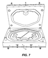
FIG. 7 is a perspective view of a cure and injection mold for a composite transmission housing according to the present invention;
FIG. 8A is a comparison of a discontinuous fiber preform process with a conventional prior art woven fabric preform process;
FIG. 8B is an automated P4A process flow diagram as compared to a conventional prior art fabric hand lay-up process;
FIG. 9A is a top perspective view of an upper composite transmission housing;
FIG. 9B is a bottom perspective view of a composite upper transmission housing;
FIG. 10 is a process flow diagram for a skin and tail take-off preforms for an upper composite transmission housing;
FIG. 11 is a P4A preform process flow diagram;
FIG. 12 is a braided preform process flow diagram;
FIG. 13 is a process flow diagram for a compression molded details for a P4A preform;
FIG. 14 is a process flow diagram for a composite upper housing preform assembly within a cure and injection mold; and
FIG. 15 is a process flow diagram for a composite upper transmission housing.
DETAILED DESCRIPTION OF THE PREFERRED EMBODIMENT
FIG. 1 illustrates a general perspective view of a main rotor support structure assembly 10 according to the present invention. The main rotor support structure assembly 10 includes a support housing 12 having a substantially cylindrical body member 14 which defines a main axis A about which a main rotor assembly (not shown) rotates. The support housing 12 is preferably manufactured from composite and/or other materials.
The main rotor support structure assembly 10 structurally supports elements of a helicopter main rotor head assembly 15 (FIG. 2) including a rotor standpipe 16 and rotor transmission housing assembly 18 with the airframe (illustrated schematically at 20.) At least one support strut 22 (two illustrated) extends from the substantially cylindrical body member 14 for securing the main rotor support structure assembly 10 to a transmission deck 24 mounted to the airframe 20. It should be understood that various other configurations will likewise benefit from the present invention.
Referring to FIG. 3, the rotor transmission housing assembly 18 includes a machined upper transmission housing 26 m, a machined lower transmission housing 28 m and a machined sump housing 30 m. That is, the housing portions 26 m, 28 m, and 30 m are illustrated after machining operations and in an installable state. It should be understood that relative positional terms such as “forward,” “aft,” “upper,” “lower,” “above,” “below,” and the like are with reference to the normal operational attitude of the vehicle and should not be considered otherwise limiting. It should also be understood that although a particular component arrangement is disclosed in the illustrated embodiment, other arrangements will benefit from the instant invention.
Referring to FIGS. 4A and 4B, the machined lower transmission housing 28 m (as illustrated in FIG. 3) is illustrated prior to machining as a lower transmission housing 28 as molded. The lower transmission housing includes a multiple of discontinuous fiber preforms 32 a-32 e such as a LH main body preform 32 a, RH main body preform 32 b, bearing build up preforms 32 c, rib preform 32 d and beehive base preform 32 e. It should be understood that any number and configuration of preform portions will benefit from the present invention.
The discontinuous fiber preforms are preferably fabricated by a Programmable Powder Preform Process for Aerospace (P4A) process such as that developed by National Composites Center, Dayton Ohio. The process is capable of fabricating both random and oriented discontinuous fiber preforms from both glass and carbon (graphite) continuous fiber raw material. It is also potentially capable of handling very high modulus pitch based carbon fiber, which may often not be practical in a woven form.
Referring to FIG. 5, a method for fabricating the preforms is illustrated in a process flow diagram. The preforms 32 a-32 e are each laid-up using contoured porous tooling attached to a vacuum system. The fibrous material is applied through a chopper head, which is attached to a programmable robot arm. Powered resin (tackifier) is also applied, in a programmed manner simultaneously with the chopped fiber. Vacuum holds the chopped fiber in place after deposition on the porous tooling. During this lay-up period other materials such as inserts, veil cloth, or woven fabric may be added to the preform as required.
After deposition of a programmed thickness of material, or the complete amount for a specific preform, a second porous tool is placed over the lay-up sandwiching it between the two porous tools. With vacuum the two tools are positioned so that the preform lay-up is consolidated to a controlled thickness. The consolidated preform, supported by the porous tools, is heated in an oven or with hot air to a temperature to fuse the powdered resin. After cooling, the preforms 32 a-32 e, which now are sufficient rigid for handling, is removed from the tooling.
Structures such as transmission housings are designed primarily for stiffness. Such structures are ideal candidates for using discontinuous fiber preforms such as the P4A preforms, because the stiffness loss (i.e. reduction in material modulus) is minimal with discontinuous versus continuous fiber properties. Also, fibrous materials not suited to weaving are readily applicable to the discontinuous form. The present invention thereby provides a new level of optimization of structural properties for stiffness.
Referring to FIG. 6, a method for fabricating the lower transmission housing 28 is illustrated in a process flow diagram. Generally, the preforms 32 a-32 e are assembled in a prepared injection and cure mold 34 (FIG. 7). Additional details and fillers (one such detail I in one preform illustrated schematically in FIG. 5) such as metal inserts, supports, reinforcements and the like are also added to the preform assembly and/or within the mold 34. Continuous fiber filler materials (illustrated schematically at F in FIG. 4B) such as unitapes, fabrics, braid, warp knit, in dry or prepreg form are also assembled into the mold 34. Preferably, the continuous fiber filler materials provide a further interface between two or more preforms 32 a-32 e which, in contrast, are formed of randomly-oriented fibers.
The preforms 32 a-32 e are preferably assembled upon a male portion 34A (FIG. 7) of the mold 34. Most preferably, the preforms 32 a-32 e are constructed such that the preforms 32 a-32 e can only be assembled into the mold 34 in a specific order and in the proper arrangement. That is, the preforms 32 a-32 e are interleaved to fit together in a manner of jig-saw puzzle pieces to prevent improper assembly.
Once the preforms 32 a-32 e are assembled into the mold 34, vacuum seals are installed, the mold 34 is closed, vacuum checked, and heated to resin infusion temperature. Using a combination of vacuum and pressure, a resin is injected into the mold to completely infuse the preform. That is, liquid molding such as resin transfer molding [RTM] or vacuum assisted resin transfer molding [VARTM] is utilized to infuse the assembled preforms 32 a-32 e within the mold 34.
Epoxies, Bismaleimides, and Cyanate Esters are preferably used with P4A fiberglass and graphite preforms 32 a-32 e for high performance applications using conventional resin transfer molding (RTM) processes.
At completion the mold 34 is heated to the resin cure temperature and held at this temperature for sufficient time to insure complete part cure. The part and the mold are cooled to a point that the part can be removed from the mold.
The part is inspected then a number of machining and finishing operations are performed. Next a number of sub-assembly operations are performed to complete the composite transmission housing 28 (FIG. 2).
Referring to FIG. 8, the present invention provides a fabrication approach that significantly reduces the fabrication costs for structures fabricated using RTM/VARTM processing as-compared to conventional hand lay-up methods of preform fabrication. FIG. 8 shows both labor & material savings (lower raw material cost of tow versus fabric & less than half as much scrap from trimming, cutting, etc).
Referring to FIGS. 9A and 9B the machined upper transmission housing 26 m (as illustrated in FIG. 2) is illustrated prior to machining as an upper transmission housing 26 as molded. The upper transmission housing 26 is manufactured as described with the lower transmission housing 28 through assembly of a multiple of discontinuous fiber preforms (as illustrated by the process flow diagrams in FIGS. 10-15). Although of a more complicated geometry which necessitates additional preforms (FIGS. 10-12) which utilize compression details themselves (FIG. 13), the upper transmission housing 26 likewise generally follows the method of: fabricating a multiple of discontinuous fiber preforms; assembling the multiple of discontinuous fiber preforms within an injection and cure mold; and resin injecting the multiple of discontinuous fiber preforms to form the final component.
The present invention utilizing the P4A preforms alone or in combination with other continuous fiber forms is particularly suited to structure, such as the disclosed composite transmission housing, that incorporates both thick and thin laminate sections with abrupt thickness transitions. The P4A process, as proposed for the disclosed transmission housing RTM preforms, is particularly suited to incorporating cured composite or metal inserts as integral parts of these preforms and hence the related structure after resin infusion and cure to provide localized strength.
The present invention may be used in the fabrication of components with similar requirements such as components which typically have thick and thin wall thickness sections, require high stiffness, large size, lightweight when compared to non composite structure, process repeatability superior to conventional hand lay-up composite processes, and quality and structural integrity typical of aerospace components.
Although particular step sequences are shown, described, and claimed, it should be understood that steps may be performed in any order, separated or combined unless otherwise indicated and will still benefit from the present invention.
The foregoing description is exemplary rather than defined by the limitations within. Many modifications and variations of the present invention are possible in light of the above teachings. The preferred embodiments of this invention have been disclosed, however, one of ordinary skill in the art would recognize that certain modifications would come within the scope of this invention. It is, therefore, to be understood that within the scope of the appended claims, the invention may be practiced otherwise than as specifically described. For that reason the following claims should be studied to determine the true scope and content of this invention.