US8325965B2 - Audio speaker having a tweeter capable of continuous rotation - Google Patents
Audio speaker having a tweeter capable of continuous rotation Download PDFInfo
- Publication number
- US8325965B2 US8325965B2 US11/649,716 US64971607A US8325965B2 US 8325965 B2 US8325965 B2 US 8325965B2 US 64971607 A US64971607 A US 64971607A US 8325965 B2 US8325965 B2 US 8325965B2
- Authority
- US
- United States
- Prior art keywords
- axis mount
- tweeter
- audio speaker
- mount assembly
- connection member
- Prior art date
- Legal status (The legal status is an assumption and is not a legal conclusion. Google has not performed a legal analysis and makes no representation as to the accuracy of the status listed.)
- Active, expires
Links
- 125000006850 spacer group Chemical group 0.000 claims abstract description 18
- 239000004020 conductor Substances 0.000 description 4
- 230000008901 benefit Effects 0.000 description 3
- 230000004048 modification Effects 0.000 description 3
- 238000012986 modification Methods 0.000 description 3
- 239000012811 non-conductive material Substances 0.000 description 3
- 230000005855 radiation Effects 0.000 description 3
- -1 but not limited to Substances 0.000 description 2
- 239000000919 ceramic Substances 0.000 description 2
- 238000010586 diagram Methods 0.000 description 2
- 239000000463 material Substances 0.000 description 2
- 239000004033 plastic Substances 0.000 description 2
- 229920003023 plastic Polymers 0.000 description 2
- 229910001369 Brass Inorganic materials 0.000 description 1
- RYGMFSIKBFXOCR-UHFFFAOYSA-N Copper Chemical compound [Cu] RYGMFSIKBFXOCR-UHFFFAOYSA-N 0.000 description 1
- 229910052782 aluminium Inorganic materials 0.000 description 1
- XAGFODPZIPBFFR-UHFFFAOYSA-N aluminium Chemical compound [Al] XAGFODPZIPBFFR-UHFFFAOYSA-N 0.000 description 1
- 239000010951 brass Substances 0.000 description 1
- 229910052802 copper Inorganic materials 0.000 description 1
- 239000010949 copper Substances 0.000 description 1
- 230000007812 deficiency Effects 0.000 description 1
- 230000003993 interaction Effects 0.000 description 1
- 229910052751 metal Inorganic materials 0.000 description 1
- 239000002184 metal Substances 0.000 description 1
- 239000004800 polyvinyl chloride Substances 0.000 description 1
- 239000002023 wood Substances 0.000 description 1
Images


Classifications
-
- H—ELECTRICITY
- H04—ELECTRIC COMMUNICATION TECHNIQUE
- H04R—LOUDSPEAKERS, MICROPHONES, GRAMOPHONE PICK-UPS OR LIKE ACOUSTIC ELECTROMECHANICAL TRANSDUCERS; DEAF-AID SETS; PUBLIC ADDRESS SYSTEMS
- H04R1/00—Details of transducers, loudspeakers or microphones
- H04R1/20—Arrangements for obtaining desired frequency or directional characteristics
- H04R1/32—Arrangements for obtaining desired frequency or directional characteristics for obtaining desired directional characteristic only
- H04R1/34—Arrangements for obtaining desired frequency or directional characteristics for obtaining desired directional characteristic only by using a single transducer with sound reflecting, diffracting, directing or guiding means
- H04R1/345—Arrangements for obtaining desired frequency or directional characteristics for obtaining desired directional characteristic only by using a single transducer with sound reflecting, diffracting, directing or guiding means for loudspeakers
-
- H—ELECTRICITY
- H04—ELECTRIC COMMUNICATION TECHNIQUE
- H04R—LOUDSPEAKERS, MICROPHONES, GRAMOPHONE PICK-UPS OR LIKE ACOUSTIC ELECTROMECHANICAL TRANSDUCERS; DEAF-AID SETS; PUBLIC ADDRESS SYSTEMS
- H04R1/00—Details of transducers, loudspeakers or microphones
- H04R1/20—Arrangements for obtaining desired frequency or directional characteristics
- H04R1/22—Arrangements for obtaining desired frequency or directional characteristics for obtaining desired frequency characteristic only
- H04R1/24—Structural combinations of separate transducers or of two parts of the same transducer and responsive respectively to two or more frequency ranges
-
- H—ELECTRICITY
- H04—ELECTRIC COMMUNICATION TECHNIQUE
- H04R—LOUDSPEAKERS, MICROPHONES, GRAMOPHONE PICK-UPS OR LIKE ACOUSTIC ELECTROMECHANICAL TRANSDUCERS; DEAF-AID SETS; PUBLIC ADDRESS SYSTEMS
- H04R2201/00—Details of transducers, loudspeakers or microphones covered by H04R1/00 but not provided for in any of its subgroups
- H04R2201/02—Details casings, cabinets or mounting therein for transducers covered by H04R1/02 but not provided for in any of its subgroups
- H04R2201/021—Transducers or their casings adapted for mounting in or to a wall or ceiling
-
- H—ELECTRICITY
- H04—ELECTRIC COMMUNICATION TECHNIQUE
- H04R—LOUDSPEAKERS, MICROPHONES, GRAMOPHONE PICK-UPS OR LIKE ACOUSTIC ELECTROMECHANICAL TRANSDUCERS; DEAF-AID SETS; PUBLIC ADDRESS SYSTEMS
- H04R2201/00—Details of transducers, loudspeakers or microphones covered by H04R1/00 but not provided for in any of its subgroups
- H04R2201/02—Details casings, cabinets or mounting therein for transducers covered by H04R1/02 but not provided for in any of its subgroups
- H04R2201/025—Transducer mountings or cabinet supports enabling variable orientation of transducer of cabinet
-
- H—ELECTRICITY
- H04—ELECTRIC COMMUNICATION TECHNIQUE
- H04R—LOUDSPEAKERS, MICROPHONES, GRAMOPHONE PICK-UPS OR LIKE ACOUSTIC ELECTROMECHANICAL TRANSDUCERS; DEAF-AID SETS; PUBLIC ADDRESS SYSTEMS
- H04R2499/00—Aspects covered by H04R or H04S not otherwise provided for in their subgroups
- H04R2499/10—General applications
- H04R2499/13—Acoustic transducers and sound field adaptation in vehicles
-
- H—ELECTRICITY
- H04—ELECTRIC COMMUNICATION TECHNIQUE
- H04R—LOUDSPEAKERS, MICROPHONES, GRAMOPHONE PICK-UPS OR LIKE ACOUSTIC ELECTROMECHANICAL TRANSDUCERS; DEAF-AID SETS; PUBLIC ADDRESS SYSTEMS
- H04R9/00—Transducers of moving-coil, moving-strip, or moving-wire type
- H04R9/06—Loudspeakers
Definitions
- the present invention is generally related to audio speakers, and more particularly is related to an audio speaker having a tweeter that is capable of continuous rotation.
- audio speakers are typically directed toward a specific location within the enclosed environment where a listener, or listeners, will be located.
- entire audio speakers are typically placed in an arrangement so that speaker projection is directed to the listener.
- speaker cabinets having audio speakers therein, may be angled to face where a listener would be located.
- openings for receiving audio speakers in an automobile are typically predefined by the manufacturer of the automobile.
- audio speakers are inserted into the predefined openings, resulting in the sound typically being projected in a direction that is not toward a passenger or driver of the automobile.
- typical locations for automobile speakers are at the bottom of a door, on a dashboard, and in the back of the automobile, however, the audio speakers typically do not face a passenger or driver of the automobile. Instead, passengers and drivers of automobiles receive audio sound after sound waves have bounced about the interior of the automobile.
- Embodiments of the present invention provide an audio speaker having a tweeter capable of continuous rotation.
- the audio speaker contains a tweeter having a top portion and a bottom portion, and an axis mount assembly, where the tweeter is removably connected to the axis mount assembly.
- the audio speaker also contains a first connection member, capable of maintaining electrical communication with the axis mount assembly throughout continuous rotation of the axis mount assembly within the audio speaker.
- the axis mount assembly contains a terminal plate capable of connecting to the bottom portion of the tweeter, wherein the terminal plate maintains electrical communication with the tweeter.
- the axis mount assembly also contains an axis mount face plate having a top portion and a bottom portion, wherein the axis mount face plate is capable of receiving the terminal plate and tweeter within an indented portion of the top portion of the axis mount face plate.
- the axis mount assembly further contains an axis mount spacer located beneath the axis mount face plate and a second connection member that maintains electrical communication with the first connection member throughout continuous rotation of the axis mount assembly within the audio speaker.
- FIG. 1A is a cross-sectional view of the present audio speaker, where a tweeter assembly is rotatably connected to the audio speaker.
- FIG. 1B is a cross-sectional line drawing illustrating the audio speaker of FIG. 1A .
- FIG. 1C further illustrates the audio speaker of FIG. 1A and FIG. 1B , without the tweeter assembly connected.
- FIG. 2 is a sectional schematic view of the tweeter assembly, located internal to the audio speaker of FIG. 1A .
- FIG. 3 further illustrates the axis mount assembly of FIG. 2 .
- FIG. 4 is a schematic diagram further illustrating the tweeter of FIG. 2 .
- FIG. 5A is a top view of the tweeter of FIG. 4 .
- FIG. 5B is a bottom view of the tweeter of FIG. 4 .
- FIG. 6A is a top view of the terminal plate of FIG. 2 .
- FIG. 6B is a bottom view of the terminal plate of FIG. 2 .
- FIG. 7A is a top view of the axis mount faceplate of FIG. 2 .
- FIG. 7B is a bottom view of the faceplate of FIG. 2 .
- FIG. 8A is a top view of the axis mount spacer of FIG. 2 .
- FIG. 8B is a bottom view of the axis mount spacer of FIG. 2 .
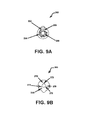
- FIG. 9A is a top view of the male PCB of FIG. 2 .
- FIG. 9B is a bottom view of the male PCB of FIG. 2 .
- FIG. 10A is a top view of the female PCB of FIG. 2 .
- FIG. 10B is a bottom view of the female PCB of FIG. 2 .
- FIG. 11 illustrates a speaker grill connected to the audio speaker of FIG. 1A .
- the audio speaker having a rotatable tweeter aiming system also referred to herein as a tweeter assembly
- the location for use of the audio speaker having the rotatable tweeter is not limited to automobiles, but instead, may be use in any environment that would benefit from having a tweeter that can be directed by rotation to optimize sound projection of the audio speaker.
- the audio speaker may be wall or ceiling mounted within a room.
- FIG. 1A is a cross-sectional view of the present audio speaker 100 , where a tweeter assembly 120 is rotatably connected to the audio speaker 100 .
- FIG. 1B is a cross-sectional line drawing illustrating the audio speaker 100 of FIG. 1A .
- the audio speaker 100 contains a back plate 102 , an electro-magnet 104 , a top plate 106 , a phase plug 108 (i.e., base), and a tweeter assembly 120 .
- the electro-magnet 104 is supported between the back plate 102 and the top plate 106 .
- the phase plug 108 is a fixed waveguide.
- the phase plug 108 has an indented central portion for receiving the tweeter assembly 120 . Since the combination of a back plate 102 , electro-magnet 104 , top plate 106 , and phase plug 108 is known, further description of functions provided by the same is not provided herein, except to mention that the combination provides the basic functionality of a woofer. Connections within the tweeter assembly 120 and interaction with the audio speaker 100 , so as to provide the capability of a tweeter and axis mount assembly rotating more that 360 degrees, is further defined herein.
- the audio speaker 100 also contains a frame 112 .
- the phase plug 108 and frame 112 may serve as heat sinks for the woofer.
- FIG. 1C further illustrates the audio speaker 100 of FIG. 1A and FIG. 1B , without the tweeter assembly 120 connected, also referred to herein as the woofer.
- FIG. 1C better illustrates the indented central portion 109 of the phase plug 108 .
- FIG. 1C also illustrates receiving holes 320 , which are described in more detail hereinbelow.
- FIG. 2 is a sectional schematic view of the tweeter assembly 120 , located internal to the audio speaker 100 , which is associated with providing the tweeter 150 with the capability of rotating over 360 degrees.
- the tweeter assembly 120 contains a tweeter 150 , an axis mount assembly 200 , a female printed circuit board (PCB) 280 , and a conductive strip 290 .
- the tweeter 150 is connected to the axis mount assembly 200 , thereby providing continuous rotational capability of the tweeter 150 .
- connection of the tweeter 150 to the axis mount assembly 200 provides a stationary connection between the tweeter 150 and the axis mount assembly 200 . Since the axis mount assembly 200 is capable of rotating over 360 degrees within the audio speaker 100 , the tweeter 150 is provided with the capability of rotating over 360 degrees within the audio speaker 100 .
- the axis mount assembly 200 contains a terminal plate 210 , an axis mount faceplate 220 , an axis mount spacer 250 , and a male PCB 260 . Each portion of the axis mount assembly 200 is described in detail herein. In addition, FIG. 3 further illustrates the axis mount assembly 200 of FIG. 2 .
- FIG. 4 is a schematic diagram further illustrating the tweeter 150 of FIG. 2 .
- FIG. 5A is a top view of the tweeter 150 of FIG. 4
- FIG. 5B is a bottom view of the tweeter 150 of FIG. 4 .
- a bottom portion 152 of the tweeter 150 contains a first conductive leg 154 , a second conductive leg 156 , and a back opening 158 , where the back opening 158 is for receiving a bolt (not shown).
- the first conductive leg 154 provides a positive electrical connection to the tweeter 150 and the second conductive leg 156 provides a negative electrical connection to the tweeter 150 .
- the tweeter 150 contains a diffuser ring 162 .
- the diffuser ring 162 is located on a top face 160 of the tweeter 150 , above a tweeter dome 164 .
- Prior use of a diffuser ring 162 has the diffuser ring 162 being mounted directly above a center line/center point of a tweeter dome and causes even radiation of acoustic energy.
- Prior use of the diffuser ring 162 is described in U.S. Pat. No. 5,689,573, entitled, “FREQUENCY-DEPENDENT AMPLITUDE MODIFICATION DEVICES FOR ACOUSTIC SOURCES”, which is hereby incorporated by reference in its entirety.
- the present tweeter 150 has the diffuser ring 162 offset from the center line/center point of the tweeter 150 . Due to the above-mentioned offset of the diffuser ring 162 from the center line/center point, the radiation pattern shifts/tilts away from the center line/center point of the tweeter dome 164 . As an example, looking at the top view provided by FIG. 5A , the diffuser ring 162 is offset so as to be shifted toward a bottom portion of the tweeter 150 top face 160 . As a result, the radiation pattern of the tweeter 150 is shifted/tilted toward the bottom portion of the tweeter 150 top face 160 .
- tweeter energy being capable of being directed when mounted.
- the audio speaker 100 is located low and forward in a door of a vehicle, the tweeter 150 energy can be directed up and back toward a listener.
- Directional control of tweeter 150 energy is provided at least by rotation of the axis mount assembly 200 .
- FIG. 6A is a top view of the terminal plate 210 of FIG. 2
- FIG. 6B is a bottom view of the terminal plate 210 of FIG. 2
- the terminal plate 210 contains a body 212 , a first connection terminal 214 , a second connection terminal 216 , a first connection wire 218 , and a second connection wire 219 .
- the body 212 is shaped so as to allow the body 212 to fit within a shaped central indented portion 222 ( FIG. 7A and FIG. 7B ) of the axis mount faceplate 220 ( FIG. 7A and FIG. 7B ).
- the body 212 is made of a nonconductive material, such as, but not limited to, plastic or ceramic.
- the terminal plate 210 made be made of polyvinyl chloride (PVC).
- the first and second connection terminals 214 , 216 are created from conductive material such as, but not limited to, brass or copper.
- the first and second connection terminals 214 , 216 are capable of snap fitting to the bottom portion 152 of the tweeter 150 .
- the first connection terminal 214 of the terminal plate 210 connects to the first conductive leg 154 of the tweeter 150 and the second connection terminal 216 of the terminal plate 210 connects to the second conductive leg 156 of the tweeter 150 .
- a conductive path is provided from the first connection wire 218 of the terminal plate 210 to the second connection terminal 216 , and a separate conductive path is provided from the second connection wire 219 of the terminal plate 210 to the first connection terminal 214 . Due to conductive paths described herein, when the terminal plate 210 is snap-fitted to the bottom of the tweeter 150 , a conductive path is provided from the first connection wire 218 of the terminal plate 210 , to the second connection terminal 216 of the terminal plate 210 , to the second conductive leg 156 of the tweeter 150 . In addition, a conductive path is provided from the second connection wire 219 of the terminal plate 210 , to the first connection terminal 214 of the terminal plate 210 , to the first conductive leg 154 of the tweeter 150 .
- the terminal plate 210 may be connected to the tweeter 150 in a manner other than being snap-fitted, as long as a conductive path is provided to the tweeter 150 .
- FIG. 7A is a top view of the axis mount faceplate 220 (hereafter, “faceplate”) of FIG. 2
- FIG. 7B is a bottom view of the faceplate 220 of FIG. 2
- the faceplate 220 is capable of receiving the terminal plate 210 within the central indented portion 222 of the faceplate 220 .
- the body 212 of the terminal plate 210 rests within the central indented portion 222 of the faceplate 220 , where the central indented portion 222 of the faceplate 220 is shaped to receive the body 212 of the terminal plate 210 .
- the faceplate 220 contains a first opening 224 , a second opening 226 , a third opening 228 , and a fourth opening 230 .
- the first opening 224 is capable of receiving a bolt that enters from the back 240 of the faceplate 220 , through the first opening 224 , and into the back opening 158 of the tweeter 150 .
- the second opening 226 is a connection wire opening capable of allowing the first and second connection wires 218 , 219 of the terminal plate 210 traverse therethrough. It should be noted that the first and second connection wires 218 , 219 of the terminal plate 210 do not connect directly to the faceplate 220 , thereby allowing the faceplate 220 to be fabricated from a conductive material. As a result, the faceplate 220 may be fabricated from different materials, including, but not limited to, aluminum, plastic, ceramic, wood or other conductive and/or non-conductive materials.
- the third opening 228 is capable of receiving an axle screw 229 ( FIG. 1B ) that traverses from a top 242 of the faceplate 220 , through the third opening 228 , through a first opening 252 ( FIG. 8A and FIG. 8B ) of the axis mount spacer 250 , through an opening of the male PCB 260 , through an opening of the female PCB 280 , and into the phase plug 108 of the audio speaker 100 .
- the axle screw 229 is a shoulder screw that is threaded into a threaded hole of the phase plug 108 , until positioned therein to prevent removal during rotation. Since shoulder screws are known to those having ordinary skill in the art, further description of the shoulder screw is not provided herein.
- the fourth opening 230 is capable of receiving a positioning bolt 244 ( FIG. 1B ) that traverses through the top of the faceplate 220 , through the fourth opening 230 , through a second opening 254 ( FIG. 8A and FIG. 8B ) of the axis mount spacer 250 , and into a top portion of the phase plug 108 .
- the phase plug 108 has a top positioning opening that is capable of receiving the positioning bolt 244 . When the positioning bolt 244 is tightened, the positioning bolt 244 locks the axis mount assembly 200 in a desired position.
- the axis mount assembly 200 is secured from rotation, after the tweeter 150 and axis mount assembly 200 have been properly directed, by tightening the positioning bolt 244 , thereby causing an intentional friction lock between the axis mount assembly 200 and the phase plug 108 .
- the tweeter 150 and axis mount assembly 200 are capable of being entirely removed from the audio speaker 100 by removal of the axle screw 229 and loosening of the positioning bolt 244 .
- a plane of the top 242 of the faceplate 220 is not perpendicular to a central axis of the audio speaker 100 . Instead, the faceplate 220 is at an angle to the central axis of the audio speaker 100 , where the faceplate 220 is angled inward toward the center of the audio speaker 100 . The angle of the faceplate 220 maintains the tweeter 150 at an angle, thereby providing for better control of sound projection. As an example, the combination of the faceplate 220 maintaining the tweeter 150 at an angle inward toward the center of the audio speaker 100 , and the offset diffuser ring 162 , results in the rotation of the tweeter 150 and axis mount assembly 200 controlling sound projection.
- the audio speaker 100 is located in a factory speaker location of an automobile, namely, in a low and forward position in a door of the vehicle, energy of the audio speaker 100 can be directed up and back toward a listener. This direction is provided by rotation of the tweeter 150 and axis mount assembly 200 within the audio speaker 100 .
- the plane of the top 242 of the faceplate 220 may be at a different angle to the central axis.
- the faceplate 220 may serve as a heat sink for the tweeter 150 , thereby improving overall system handling of the audio speaker 100 .
- FIG. 8A is a top view of the axis mount spacer 250 of FIG. 2
- FIG. 8B is a bottom view of the axis mount spacer 250 of FIG. 2
- the axis mount spacer 250 contains a first opening 252 and a second opening 254 .
- the first opening 252 is capable of allowing the axle screw 229 and the first and second connection wires 218 , 219 traverse therethrough.
- the second opening 254 is capable of allowing the positioning bolt 224 traverse therethrough.
- the axis mount spacer 250 also dictates a distance that the tweeter 150 and axis mount assembly 200 extend out from the audio speaker 100 .
- the axis mount spacer 250 may be removed from the axis mount assembly 200 , or the axis mount spacer 250 may be formed as an extension of the axis mount face plate 220 .
- FIG. 9A is a top view of the male PCB 260 of FIG. 2 and FIG. 9B is a bottom view of the male PCB 260 of FIG. 2 .
- the top portion of the male PCB 260 contains a first conductive pad 262 and a second conductive pad 266 .
- the first conductive pad 262 has a positive polarity and receives the second connection wire 219 of the terminal plate 210 .
- a first conductive path 264 is connected to the first conductive pad 262 .
- the second conductive pad 266 has a negative polarity and receives the first connection wire 218 of the terminal plate 210 .
- a second conductive path 268 is connected to the second conductive pad 266 .
- the bottom portion of the male PCB 260 contains a first set of conductive pins 270 and a second set of conductive pins 272 .
- the first set of conductive pins 270 are conductively connected to the first conductive path 264
- the second set of conductive pins 272 are conductively connected to the second conductive path 268 .
- the first set of conductive pins 270 have a positive polarity
- the second set of conductive pins 272 have a negative polarity.
- the first and second sets of conductive pins 270 , 272 are shown to have three conductive pins each, the number of conductive pins may be more or fewer.
- FIG. 10A is a top view of the female PCB 280 of FIG. 2 and FIG. 10B is a bottom view of the female PCB 280 of FIG. 2 .
- a top portion of the female PCB 280 contains a first concentric trace 282 and a second concentric trace 284 .
- the first concentric trace 282 is capable of receiving the first set of pins 270 and has a positive polarity
- the second concentric trace 284 is capable of receiving the second set of pins 272 and has a negative polarity.
- the concentric traces 282 , 284 are spaced apart so that one concentric trace is located outside of the other. It should be noted, however, that it does not matter which of the two concentric traces 282 , 284 is located on the outside or inside.
- the female PCB 280 contains a first conductive contact 286 and a second conductive contact 288 , where the first conductive contact 286 has a positive polarity and the second conductive contact 288 has a negative polarity.
- the conductive strip 290 is connected to the first and second conductive contacts 286 , 288 , where a positive lead of the conductive strip 290 is connected to the first conductive contact 286 and a negative lead of the conductive strip 290 is connected to the second conductive contact 288 .
- the conductive strip 290 is flat and flexible, and contains a first conductive path and a second conductive path located between two layers of non-conductive material.
- the first and second conductive paths may be flat metal conductors.
- the positive lead of the conductive strip 290 is connected to the first conductive path within the conductive strip 290 and the negative lead of the conductive strip 290 is connected to the second conductive path within the conductive strip 290 .
- the first and second set of pins 270 , 272 conductively communicate with the first and second concentric traces 282 , 284 , respectively.
- Pressure to push the sets of pins 270 , 272 onto the concentric traces 282 , 284 may be provided by, for example, a series of springs.
- a first set of springs may cause the first set of pins 270 to press against the first concentric trace 282
- a second set of springs may cause the second set of pins 272 to press against the second concentric trace 284 .
- a rubber bumper or other material may be provided for maintaining conductive communication between the pins and traces.
- the axis mount assembly 200 Since conductive communication between the male PCB 260 and the female PCB 280 is maintained by the pin/concentric trace relationship, the axis mount assembly 200 , having the tweeter 150 therein, is capable of continuous and infinite variability of rotation and any degree of 360 can be set without binding. It should be noted that, in accordance with an alternative embodiment of the invention, the male PCB 260 and the female PCB 280 may be in opposite locations, where the female PCB 280 is instead a portion of the axis mount assembly 200 , and the male PCB 260 is connected to the conductive strip 290 . In addition, the pins may be replaced by different conductive members that are capable of maintaining connection to the concentric traces.
- the conductive strip 290 may traverse an outer portion of the audio speaker 100 frame 112 , to a mounting location (not shown) located on an outer side portion of the frame 112 .
- the mounting location has a positive connection port (not shown) and a negative connection port (not shown).
- a speaker grill 300 may be provided that is capable of being rotated without full disassembly from the audio speaker 100 .
- Locking bolts 310 provide this capability, where optionally, the locking bolts 310 may not allow the speaker grill 300 to be fully removed from the audio speaker 100 .
- the locking bolts 310 are capable of being received by the receiving holes 320 of the audio speaker frame 112 .
Abstract
Description
Claims (22)
Priority Applications (1)
| Application Number | Priority Date | Filing Date | Title |
|---|---|---|---|
| US11/649,716 US8325965B2 (en) | 2006-01-04 | 2007-01-04 | Audio speaker having a tweeter capable of continuous rotation |
Applications Claiming Priority (2)
| Application Number | Priority Date | Filing Date | Title |
|---|---|---|---|
| US75615806P | 2006-01-04 | 2006-01-04 | |
| US11/649,716 US8325965B2 (en) | 2006-01-04 | 2007-01-04 | Audio speaker having a tweeter capable of continuous rotation |
Publications (2)
| Publication Number | Publication Date |
|---|---|
| US20070189557A1 US20070189557A1 (en) | 2007-08-16 |
| US8325965B2 true US8325965B2 (en) | 2012-12-04 |
Family
ID=38256880
Family Applications (2)
| Application Number | Title | Priority Date | Filing Date |
|---|---|---|---|
| US12/160,912 Abandoned US20090003633A1 (en) | 2006-01-04 | 2007-01-04 | Filter Element |
| US11/649,716 Active 2030-11-25 US8325965B2 (en) | 2006-01-04 | 2007-01-04 | Audio speaker having a tweeter capable of continuous rotation |
Family Applications Before (1)
| Application Number | Title | Priority Date | Filing Date |
|---|---|---|---|
| US12/160,912 Abandoned US20090003633A1 (en) | 2006-01-04 | 2007-01-04 | Filter Element |
Country Status (6)
| Country | Link |
|---|---|
| US (2) | US20090003633A1 (en) |
| EP (1) | EP1969900B1 (en) |
| JP (1) | JP2009522931A (en) |
| RU (1) | RU2436256C2 (en) |
| TW (1) | TW200806065A (en) |
| WO (1) | WO2007081712A2 (en) |
Cited By (3)
| Publication number | Priority date | Publication date | Assignee | Title |
|---|---|---|---|---|
| US9743164B2 (en) | 2015-03-30 | 2017-08-22 | Bose Corporation | Displaceable speaker array and related assemblies |
| US20220194303A1 (en) * | 2020-12-21 | 2022-06-23 | Harman International Industries, Incorporated | Tweeter flush, surface, and starfish mount installation |
| US11470410B1 (en) * | 2021-05-17 | 2022-10-11 | Coastal Source, LLC | Speaker mounting system and method of mounting within a panel |
Families Citing this family (5)
| Publication number | Priority date | Publication date | Assignee | Title |
|---|---|---|---|---|
| US8229155B2 (en) * | 2008-05-07 | 2012-07-24 | Three Amigos LLC | Speaker assembly with directional adjustability |
| US9906847B2 (en) * | 2008-08-17 | 2018-02-27 | Doug S. Wright | Speaker mountings |
| US20110281493A1 (en) * | 2010-05-11 | 2011-11-17 | Barley Christopher B | Electronic wildlife call |
| US10241746B2 (en) | 2017-05-01 | 2019-03-26 | Mastercraft Boat Company, Llc | Control and audio systems for a boat |
| US10484767B1 (en) * | 2018-04-25 | 2019-11-19 | Jl Audio, Inc. | Loudspeaker system with multi-component grill assembly |
Citations (43)
| Publication number | Priority date | Publication date | Assignee | Title |
|---|---|---|---|---|
| US4165797A (en) | 1977-06-06 | 1979-08-28 | Mack Spetalnik | Adjustable high frequency sound dispersion system |
| US4365114A (en) | 1979-09-14 | 1982-12-21 | Pioneer Electronic Corporation | Automotive loudspeaker having variable speaker orientation and particular electrical connections |
| JPS5948193A (en) | 1982-09-09 | 1984-03-19 | 小林 廣 | Method of detecting finish of bookbinding |
| US4441577A (en) | 1981-10-30 | 1984-04-10 | Clarion Co., Ltd | Direction-variable speaker system |
| US4554414A (en) | 1983-04-28 | 1985-11-19 | Harman International Industries Incorporated | Multi-driver loudspeaker |
| US4553630A (en) | 1984-01-19 | 1985-11-19 | Pioneer Electronic Corporation | Speaker with tweeter angle adjusting device |
| JPS6213197A (en) * | 1985-07-11 | 1987-01-21 | Matsushita Electric Ind Co Ltd | Coaxial speaker |
| JPS63203365A (en) | 1987-02-20 | 1988-08-23 | Canon Inc | Ink ribbon |
| US4811406A (en) | 1982-03-31 | 1989-03-07 | Pioneer Electronic Corporation | Compound speaker system |
| US4875233A (en) * | 1987-10-16 | 1989-10-17 | Derhaag Robert L | Headset construction and method of making same |
| US5148490A (en) | 1990-10-01 | 1992-09-15 | Culver Electronic Sales, Inc. | Speaker with tweeter assembly mounted to the interior of the windshield of a vehicle |
| US5181253A (en) | 1991-01-08 | 1993-01-19 | Southern Audio Services, Inc. | Loudspeaker assembly |
| JPH06269076A (en) | 1993-03-16 | 1994-09-22 | Sanyo Electric Co Ltd | Coaxial speaker |
| JPH0798831A (en) | 1993-09-30 | 1995-04-11 | Kao Corp | Magnetic recording medium, its production and producing device |
| JPH07287941A (en) | 1994-04-18 | 1995-10-31 | Sony Corp | Clock generating device for digital data |
| JPH07300853A (en) | 1994-05-02 | 1995-11-14 | Shohei Senda | Method for improving soft ground and device therefor |
| US5512714A (en) | 1994-06-23 | 1996-04-30 | Fenton; Robert | Composite speaker system having a directional adjustable tweeter |
| US5568562A (en) * | 1994-11-28 | 1996-10-22 | Vocal Co., Ltd. | Releasably mounted compound loudspeakers |
| US5629501A (en) | 1994-06-23 | 1997-05-13 | Fenton; Robert | Composite speaker system having a directional adjustable transducer |
| US5751821A (en) | 1993-10-28 | 1998-05-12 | Mcintosh Laboratory, Inc. | Speaker system with reconfigurable, high-frequency dispersion pattern |
| US5859917A (en) * | 1997-08-04 | 1999-01-12 | Infinity Systems Inc. | Flush-mount swivel tweeter system for vehicular audio |
| US6002780A (en) | 1998-07-06 | 1999-12-14 | Harman International Industries, Incorporated | Audio speaker having rotatable tweeter |
| US6026927A (en) | 1998-09-04 | 2000-02-22 | Niles Audio Corporation, Inc. | Speaker assembly |
| US6070694A (en) | 1998-09-04 | 2000-06-06 | Niles Audio Corporation, Inc. | Loudspeaker assembly |
| US6101262A (en) | 1999-01-07 | 2000-08-08 | Speakercraft, Inc. | Flush-mount pivoting speaker |
| JP2001147940A (en) | 1999-11-22 | 2001-05-29 | Toshiba Corp | Retrieval system and retrieval method |
| JP2001157291A (en) | 1999-11-29 | 2001-06-08 | Onkyo Corp | Tweeter unit simply attachable to/detachable from speaker |
| US6282297B1 (en) | 2000-07-12 | 2001-08-28 | Steff Lin | Angle adjustment structure for speaker system |
| WO2002019761A2 (en) | 2000-08-31 | 2002-03-07 | Niles Audio Corporation | Pivoting and rotating loudspeaker assembly |
| US6356640B1 (en) | 2001-05-16 | 2002-03-12 | Steff Lin | Direction adjusting arrangement for tweeter |
| US6374942B1 (en) | 2000-01-21 | 2002-04-23 | John M. Huggins | System and method for a combined rotatable mechanical and electrical speaker mounting system |
| US20020081980A1 (en) | 2000-12-27 | 2002-06-27 | Reus Richard J. | Sound reproduction apparatus for use in vehicular audio applications |
| US20030044039A1 (en) | 2001-08-31 | 2003-03-06 | Frank Sterns | Interchangeable pivoting loudspeaker assembly with spring retained high frequency transducer |
| US20030142844A1 (en) | 2001-11-21 | 2003-07-31 | Rivera Dean M. | Dual-tweeter loudspeaker |
| WO2004030408A1 (en) | 2002-09-27 | 2004-04-08 | Boston Acoustics, Inc. | Loud speaker |
| US6724907B1 (en) | 2002-11-15 | 2004-04-20 | Yen-Chen Chan | Tweeter support rack structure |
| US6792125B1 (en) | 2000-08-23 | 2004-09-14 | Boston Acoustics, Inc. | Pivotable speaker mounting apparatus |
| US6876752B1 (en) | 1995-01-06 | 2005-04-05 | Godehard A. Guenther | Loudspeakers systems and components thereof |
| US20050123156A1 (en) | 2003-08-26 | 2005-06-09 | Wright Doug S. | Audio device post extension and angling system |
| US20050265566A1 (en) | 2004-05-31 | 2005-12-01 | Honda Motor Co., Ltd. | Motorcycle with acoustic system |
| JP2005340924A (en) | 2004-05-24 | 2005-12-08 | Matsushita Electric Ind Co Ltd | Information reproducing apparatus |
| US20060023903A1 (en) | 2004-07-27 | 2006-02-02 | Minebea Co., Ltd. | Coaxial speaker including support member having hollow to function as back cavity |
| US7801323B2 (en) * | 2003-07-24 | 2010-09-21 | Floyd Bell, Inc. | Sound modifying cap for housing |
Family Cites Families (12)
| Publication number | Priority date | Publication date | Assignee | Title |
|---|---|---|---|---|
| US518253A (en) * | 1894-04-17 | Sash-fastener | ||
| JPS58149887U (en) * | 1982-03-31 | 1983-10-07 | パイオニア株式会社 | Composite speaker system |
| JPS5948193U (en) * | 1982-11-22 | 1984-03-30 | パイオニア株式会社 | Composite speaker system |
| JPS60111192U (en) * | 1983-12-28 | 1985-07-27 | フオスタ−電機株式会社 | composite speaker |
| DE4134223C1 (en) * | 1991-10-16 | 1992-11-12 | Stora Feldmuehle Ag, 4000 Duesseldorf, De | |
| US5689573A (en) | 1992-01-07 | 1997-11-18 | Boston Acoustics, Inc. | Frequency-dependent amplitude modification devices for acoustic sources |
| FR2720953B1 (en) * | 1994-06-08 | 1996-08-30 | Tami Ind | Multichannel inorganic element for the filtration of a fluid. |
| FR2741821B1 (en) * | 1995-12-05 | 1998-02-20 | Tami Ind | INORGANIC FILTRATION TUBULAR ELEMENT HAVING INCREASED FILTRATION SURFACE AND MECHANICAL STRENGTH |
| JPH11331975A (en) * | 1998-05-18 | 1999-11-30 | Kenwood Corp | Structure for speaker |
| FR2805331B1 (en) * | 2000-02-21 | 2002-05-31 | Ceramiques Tech Soc D | MULTICHANNEL ELEMENT AND METHOD FOR MANUFACTURING SUCH AN ELEMENT |
| JP2004015148A (en) * | 2002-06-04 | 2004-01-15 | Kenwood Corp | Wiring structure for composite speaker |
| JP2004023433A (en) * | 2002-06-17 | 2004-01-22 | Kenwood Corp | Composite speaker |
-
2007
- 2007-01-04 US US12/160,912 patent/US20090003633A1/en not_active Abandoned
- 2007-01-04 RU RU2008131933/28A patent/RU2436256C2/en not_active IP Right Cessation
- 2007-01-04 JP JP2008549544A patent/JP2009522931A/en active Pending
- 2007-01-04 US US11/649,716 patent/US8325965B2/en active Active
- 2007-01-04 WO PCT/US2007/000089 patent/WO2007081712A2/en active Application Filing
- 2007-01-04 EP EP07716251.9A patent/EP1969900B1/en active Active
- 2007-01-04 TW TW096100347A patent/TW200806065A/en unknown
Patent Citations (46)
| Publication number | Priority date | Publication date | Assignee | Title |
|---|---|---|---|---|
| US4165797A (en) | 1977-06-06 | 1979-08-28 | Mack Spetalnik | Adjustable high frequency sound dispersion system |
| US4365114A (en) | 1979-09-14 | 1982-12-21 | Pioneer Electronic Corporation | Automotive loudspeaker having variable speaker orientation and particular electrical connections |
| US4441577A (en) | 1981-10-30 | 1984-04-10 | Clarion Co., Ltd | Direction-variable speaker system |
| US4811406A (en) | 1982-03-31 | 1989-03-07 | Pioneer Electronic Corporation | Compound speaker system |
| JPS5948193A (en) | 1982-09-09 | 1984-03-19 | 小林 廣 | Method of detecting finish of bookbinding |
| US4554414A (en) | 1983-04-28 | 1985-11-19 | Harman International Industries Incorporated | Multi-driver loudspeaker |
| US4553630A (en) | 1984-01-19 | 1985-11-19 | Pioneer Electronic Corporation | Speaker with tweeter angle adjusting device |
| JPS6213197A (en) * | 1985-07-11 | 1987-01-21 | Matsushita Electric Ind Co Ltd | Coaxial speaker |
| JPS63203365A (en) | 1987-02-20 | 1988-08-23 | Canon Inc | Ink ribbon |
| US4875233A (en) * | 1987-10-16 | 1989-10-17 | Derhaag Robert L | Headset construction and method of making same |
| US5148490A (en) | 1990-10-01 | 1992-09-15 | Culver Electronic Sales, Inc. | Speaker with tweeter assembly mounted to the interior of the windshield of a vehicle |
| US5181253A (en) | 1991-01-08 | 1993-01-19 | Southern Audio Services, Inc. | Loudspeaker assembly |
| JPH06269076A (en) | 1993-03-16 | 1994-09-22 | Sanyo Electric Co Ltd | Coaxial speaker |
| JPH0798831A (en) | 1993-09-30 | 1995-04-11 | Kao Corp | Magnetic recording medium, its production and producing device |
| US5751821A (en) | 1993-10-28 | 1998-05-12 | Mcintosh Laboratory, Inc. | Speaker system with reconfigurable, high-frequency dispersion pattern |
| JPH07287941A (en) | 1994-04-18 | 1995-10-31 | Sony Corp | Clock generating device for digital data |
| JPH07300853A (en) | 1994-05-02 | 1995-11-14 | Shohei Senda | Method for improving soft ground and device therefor |
| US5512714A (en) | 1994-06-23 | 1996-04-30 | Fenton; Robert | Composite speaker system having a directional adjustable tweeter |
| US5629501A (en) | 1994-06-23 | 1997-05-13 | Fenton; Robert | Composite speaker system having a directional adjustable transducer |
| US5635686A (en) | 1994-06-23 | 1997-06-03 | Fenton; Robert | Composite speaker system having a directional adjustable tweeter |
| US5568562A (en) * | 1994-11-28 | 1996-10-22 | Vocal Co., Ltd. | Releasably mounted compound loudspeakers |
| US6876752B1 (en) | 1995-01-06 | 2005-04-05 | Godehard A. Guenther | Loudspeakers systems and components thereof |
| US5859917A (en) * | 1997-08-04 | 1999-01-12 | Infinity Systems Inc. | Flush-mount swivel tweeter system for vehicular audio |
| US6002780A (en) | 1998-07-06 | 1999-12-14 | Harman International Industries, Incorporated | Audio speaker having rotatable tweeter |
| US6070694A (en) | 1998-09-04 | 2000-06-06 | Niles Audio Corporation, Inc. | Loudspeaker assembly |
| US6026927A (en) | 1998-09-04 | 2000-02-22 | Niles Audio Corporation, Inc. | Speaker assembly |
| US6101262A (en) | 1999-01-07 | 2000-08-08 | Speakercraft, Inc. | Flush-mount pivoting speaker |
| JP2001147940A (en) | 1999-11-22 | 2001-05-29 | Toshiba Corp | Retrieval system and retrieval method |
| JP2001157291A (en) | 1999-11-29 | 2001-06-08 | Onkyo Corp | Tweeter unit simply attachable to/detachable from speaker |
| US6374942B1 (en) | 2000-01-21 | 2002-04-23 | John M. Huggins | System and method for a combined rotatable mechanical and electrical speaker mounting system |
| US6282297B1 (en) | 2000-07-12 | 2001-08-28 | Steff Lin | Angle adjustment structure for speaker system |
| US6792125B1 (en) | 2000-08-23 | 2004-09-14 | Boston Acoustics, Inc. | Pivotable speaker mounting apparatus |
| WO2002019761A2 (en) | 2000-08-31 | 2002-03-07 | Niles Audio Corporation | Pivoting and rotating loudspeaker assembly |
| US20020081980A1 (en) | 2000-12-27 | 2002-06-27 | Reus Richard J. | Sound reproduction apparatus for use in vehicular audio applications |
| US6356640B1 (en) | 2001-05-16 | 2002-03-12 | Steff Lin | Direction adjusting arrangement for tweeter |
| US6683963B2 (en) | 2001-08-31 | 2004-01-27 | Niles Audio Corporation | Interchangeable pivoting loudspeaker assembly with spring retained high frequency transducer |
| US20030044039A1 (en) | 2001-08-31 | 2003-03-06 | Frank Sterns | Interchangeable pivoting loudspeaker assembly with spring retained high frequency transducer |
| US20030142844A1 (en) | 2001-11-21 | 2003-07-31 | Rivera Dean M. | Dual-tweeter loudspeaker |
| WO2004030408A1 (en) | 2002-09-27 | 2004-04-08 | Boston Acoustics, Inc. | Loud speaker |
| US6724907B1 (en) | 2002-11-15 | 2004-04-20 | Yen-Chen Chan | Tweeter support rack structure |
| US7801323B2 (en) * | 2003-07-24 | 2010-09-21 | Floyd Bell, Inc. | Sound modifying cap for housing |
| US20050123156A1 (en) | 2003-08-26 | 2005-06-09 | Wright Doug S. | Audio device post extension and angling system |
| US7121756B2 (en) | 2003-08-26 | 2006-10-17 | Conextion Systems, Inc. | Audio device post extension and angling system |
| JP2005340924A (en) | 2004-05-24 | 2005-12-08 | Matsushita Electric Ind Co Ltd | Information reproducing apparatus |
| US20050265566A1 (en) | 2004-05-31 | 2005-12-01 | Honda Motor Co., Ltd. | Motorcycle with acoustic system |
| US20060023903A1 (en) | 2004-07-27 | 2006-02-02 | Minebea Co., Ltd. | Coaxial speaker including support member having hollow to function as back cavity |
Cited By (4)
| Publication number | Priority date | Publication date | Assignee | Title |
|---|---|---|---|---|
| US9743164B2 (en) | 2015-03-30 | 2017-08-22 | Bose Corporation | Displaceable speaker array and related assemblies |
| US20220194303A1 (en) * | 2020-12-21 | 2022-06-23 | Harman International Industries, Incorporated | Tweeter flush, surface, and starfish mount installation |
| US11780378B2 (en) * | 2020-12-21 | 2023-10-10 | Harman International Industries, Incorporated | Tweeter flush, surface, and starfish mount installation |
| US11470410B1 (en) * | 2021-05-17 | 2022-10-11 | Coastal Source, LLC | Speaker mounting system and method of mounting within a panel |
Also Published As
| Publication number | Publication date |
|---|---|
| WO2007081712A3 (en) | 2008-08-07 |
| TW200806065A (en) | 2008-01-16 |
| WO2007081712A2 (en) | 2007-07-19 |
| EP1969900B1 (en) | 2017-10-11 |
| RU2008131933A (en) | 2010-02-10 |
| RU2436256C2 (en) | 2011-12-10 |
| US20090003633A1 (en) | 2009-01-01 |
| JP2009522931A (en) | 2009-06-11 |
| EP1969900A2 (en) | 2008-09-17 |
| EP1969900A4 (en) | 2010-07-28 |
| US20070189557A1 (en) | 2007-08-16 |
Similar Documents
| Publication | Publication Date | Title |
|---|---|---|
| US8325965B2 (en) | Audio speaker having a tweeter capable of continuous rotation | |
| US11407362B1 (en) | Sound bar for mounting on a recreational land vehicle or watercraft | |
| US8837767B2 (en) | Loudspeaker system | |
| US8116099B2 (en) | Circuit board device, electronic device provided with the same, and GND connecting method | |
| WO2017128858A1 (en) | Sound chamber structure and terminal | |
| CN1910904B (en) | Monitor camera and dehumidifying adjusting body | |
| US8948436B2 (en) | Loudspeaker system | |
| US7374427B2 (en) | Coaxial cable distributor | |
| US11476565B2 (en) | Patch antenna and antenna device for vehicle | |
| WO2005081581A1 (en) | A parallelepiped type directional condenser microphone | |
| TW201841103A (en) | Embedded device | |
| US6798892B2 (en) | Rotatable removeable speaker assembly | |
| US6801632B2 (en) | Microphone assembly for vehicular installation | |
| KR20180002172U (en) | a camera housing of hinge-type-rear-facing camera | |
| US10644392B2 (en) | Lighting device cover with built-in antenna | |
| JP5508911B2 (en) | Wireless base station | |
| JPH05152820A (en) | Antenna system | |
| JP2008041551A (en) | Connector for electric component and microphone unit | |
| CN212012719U (en) | Security and protection equipment | |
| TWI690213B (en) | Planar module sound device | |
| JP2008131191A (en) | Condenser microphone unit | |
| JP2002264722A (en) | Room lamp unit for automobile | |
| CN114071317A (en) | Sound post capable of freely combining loudspeaker directions | |
| JP2000101318A (en) | Portable communication equipment | |
| JPH10294982A (en) | Loud speaker and telephone system provided with the loud speaker |
Legal Events
| Date | Code | Title | Description |
|---|---|---|---|
| AS | Assignment |
Owner name: BOSTON ACOUSTICS, INC., MASSACHUSETTS Free format text: ASSIGNMENT OF ASSIGNORS INTEREST;ASSIGNORS:BLACKMON, LEIF;COX, BRIAN;HIGGINS, TIM;REEL/FRAME:019127/0454;SIGNING DATES FROM 20070313 TO 20070402 Owner name: BOSTON ACOUSTICS, INC., MASSACHUSETTS Free format text: ASSIGNMENT OF ASSIGNORS INTEREST;ASSIGNORS:BLACKMON, LEIF;COX, BRIAN;HIGGINS, TIM;SIGNING DATES FROM 20070313 TO 20070402;REEL/FRAME:019127/0454 |
|
| AS | Assignment |
Owner name: MIZUHO CORPORATE BANK, LTD., LONDON BRANCH AS OFFS Free format text: SECURITY AGREEMENT;ASSIGNOR:BOSTON ACOUSTICS, INC.;REEL/FRAME:024686/0239 Effective date: 20090313 |
|
| STCF | Information on status: patent grant |
Free format text: PATENTED CASE |
|
| FPAY | Fee payment |
Year of fee payment: 4 |
|
| AS | Assignment |
Owner name: DIGITAL NETWORKS NORTH AMERICA, INC., CALIFORNIA Free format text: TERMINATION AND RELEASE OF SECURITY INTEREST;ASSIGNOR:MIZUHO BANK, LTD., LONDON BRANCH;REEL/FRAME:041843/0928 Effective date: 20170228 Owner name: BOSTON ACOUSTICS, INC., CALIFORNIA Free format text: TERMINATION AND RELEASE OF SECURITY INTEREST;ASSIGNOR:MIZUHO BANK, LTD., LONDON BRANCH;REEL/FRAME:041843/0928 Effective date: 20170228 |
|
| AS | Assignment |
Owner name: CERBERUS BUSINESS FINANCE, LLC, AS COLLATERAL AGENT, NEW YORK Free format text: NOTICE OF SECURITY INTEREST -- PATENTS;ASSIGNORS:POLK AUDIO, LLC;DIRECTED, LLC;DEFINITIVE TECHNOLOGY, LLC;AND OTHERS;REEL/FRAME:041909/0611 Effective date: 20170228 Owner name: CERBERUS BUSINESS FINANCE, LLC, AS COLLATERAL AGEN Free format text: NOTICE OF SECURITY INTEREST -- PATENTS;ASSIGNORS:POLK AUDIO, LLC;DIRECTED, LLC;DEFINITIVE TECHNOLOGY, LLC;AND OTHERS;REEL/FRAME:041909/0611 Effective date: 20170228 |
|
| MAFP | Maintenance fee payment |
Free format text: PAYMENT OF MAINTENANCE FEE, 8TH YEAR, LARGE ENTITY (ORIGINAL EVENT CODE: M1552); ENTITY STATUS OF PATENT OWNER: LARGE ENTITY Year of fee payment: 8 |
|
| AS | Assignment |
Owner name: CERBERUS BUSINESS FINANCE, LLC, AS THE COLLATERAL AGENT, NEW YORK Free format text: NOTICE OF SECURITY INTEREST - PATENTS;ASSIGNORS:DEI SALES, INC.;D&M HOLDINGS U.S. INC.;BOSTON ACOUSTICS, INC.;AND OTHERS;REEL/FRAME:054300/0611 Effective date: 20201009 |
|
| AS | Assignment |
Owner name: BANK OF AMERICA, N.A., AS COLLATERAL AGENT, NORTH CAROLINA Free format text: ABL PATENT SECURITY AGREEMENT;ASSIGNORS:BOSTON ACOUSTICS, INC.;DEI SALES, INC.;DEI HOLDINGS, INC.;AND OTHERS;REEL/FRAME:056193/0207 Effective date: 20210429 Owner name: BANK OF AMERICA, N.A., AS COLLATERAL AGENT, NORTH CAROLINA Free format text: FIRST LIEN PATENT SECURITY AGREEMENT;ASSIGNORS:BOSTON ACOUSTICS, INC.;DEI SALES, INC.;DEI HOLDINGS, INC.;AND OTHERS;REEL/FRAME:056193/0230 Effective date: 20210429 |
|
| AS | Assignment |
Owner name: D&M HOLDINGS INC., CALIFORNIA Free format text: RELEASE OF SECURITY INTEREST IN INTELLECTUAL PROPERTY;ASSIGNOR:CERBERUS BUSINESS FINANCE, LLC, AS AGENT;REEL/FRAME:059127/0278 Effective date: 20210429 Owner name: B & W LOUDSPEAKERS LTD, UNITED KINGDOM Free format text: RELEASE OF SECURITY INTEREST IN INTELLECTUAL PROPERTY;ASSIGNOR:CERBERUS BUSINESS FINANCE, LLC, AS AGENT;REEL/FRAME:059127/0278 Effective date: 20210429 Owner name: SOUND UNITED, LLC, CALIFORNIA Free format text: RELEASE OF SECURITY INTEREST IN INTELLECTUAL PROPERTY;ASSIGNOR:CERBERUS BUSINESS FINANCE, LLC, AS AGENT;REEL/FRAME:059127/0278 Effective date: 20210429 Owner name: B & W GROUP LTD, UNITED KINGDOM Free format text: RELEASE OF SECURITY INTEREST IN INTELLECTUAL PROPERTY;ASSIGNOR:CERBERUS BUSINESS FINANCE, LLC, AS AGENT;REEL/FRAME:059127/0278 Effective date: 20210429 Owner name: D&M EUROPE B.V., CALIFORNIA Free format text: RELEASE OF SECURITY INTEREST IN INTELLECTUAL PROPERTY;ASSIGNOR:CERBERUS BUSINESS FINANCE, LLC, AS AGENT;REEL/FRAME:059127/0278 Effective date: 20210429 Owner name: BOSTON ACOUSTICS, INC., CALIFORNIA Free format text: RELEASE OF SECURITY INTEREST IN INTELLECTUAL PROPERTY;ASSIGNOR:CERBERUS BUSINESS FINANCE, LLC, AS AGENT;REEL/FRAME:059127/0278 Effective date: 20210429 Owner name: DEFINITIVE TECHNOLOGY, LLC, CALIFORNIA Free format text: RELEASE OF SECURITY INTEREST IN INTELLECTUAL PROPERTY;ASSIGNOR:CERBERUS BUSINESS FINANCE, LLC, AS AGENT;REEL/FRAME:059127/0278 Effective date: 20210429 Owner name: DIRECTED, LLC, CALIFORNIA Free format text: RELEASE OF SECURITY INTEREST IN INTELLECTUAL PROPERTY;ASSIGNOR:CERBERUS BUSINESS FINANCE, LLC, AS AGENT;REEL/FRAME:059127/0278 Effective date: 20210429 Owner name: POLK AUDIO, LLC, CALIFORNIA Free format text: RELEASE OF SECURITY INTEREST IN INTELLECTUAL PROPERTY;ASSIGNOR:CERBERUS BUSINESS FINANCE, LLC, AS AGENT;REEL/FRAME:059127/0278 Effective date: 20210429 |
|
| AS | Assignment |
Owner name: EQUITY INTERNATIONAL LLC, MASSACHUSETTS Free format text: RELEASE OF SECURITY INTEREST IN PATENT COLLATERAL (REEL/FRAME 056193/0207);ASSIGNOR:BANK OF AMERICA, N.A., AS COLLATERAL AGENT;REEL/FRAME:059988/0637 Effective date: 20220404 Owner name: D&M PREMIUM SOUD SOLUTIONS, LLC, CALIFORNIA Free format text: RELEASE OF SECURITY INTEREST IN PATENT COLLATERAL (REEL/FRAME 056193/0207);ASSIGNOR:BANK OF AMERICA, N.A., AS COLLATERAL AGENT;REEL/FRAME:059988/0637 Effective date: 20220404 Owner name: BOSTON ACOUSTICS, INC., CALIFORNIA Free format text: RELEASE OF SECURITY INTEREST IN PATENT COLLATERAL (REEL/FRAME 056193/0207);ASSIGNOR:BANK OF AMERICA, N.A., AS COLLATERAL AGENT;REEL/FRAME:059988/0637 Effective date: 20220404 Owner name: D&M DIRECT, INC., CALIFORNIA Free format text: RELEASE OF SECURITY INTEREST IN PATENT COLLATERAL (REEL/FRAME 056193/0207);ASSIGNOR:BANK OF AMERICA, N.A., AS COLLATERAL AGENT;REEL/FRAME:059988/0637 Effective date: 20220404 Owner name: D & M SALES & MARKETING AMERICAS LLC, CALIFORNIA Free format text: RELEASE OF SECURITY INTEREST IN PATENT COLLATERAL (REEL/FRAME 056193/0207);ASSIGNOR:BANK OF AMERICA, N.A., AS COLLATERAL AGENT;REEL/FRAME:059988/0637 Effective date: 20220404 Owner name: MARANTZ AMERICA, LLC, CALIFORNIA Free format text: RELEASE OF SECURITY INTEREST IN PATENT COLLATERAL (REEL/FRAME 056193/0207);ASSIGNOR:BANK OF AMERICA, N.A., AS COLLATERAL AGENT;REEL/FRAME:059988/0637 Effective date: 20220404 Owner name: DENEN ELECTRONICS (USA), LLC, CALIFORNIA Free format text: RELEASE OF SECURITY INTEREST IN PATENT COLLATERAL (REEL/FRAME 056193/0207);ASSIGNOR:BANK OF AMERICA, N.A., AS COLLATERAL AGENT;REEL/FRAME:059988/0637 Effective date: 20220404 Owner name: THE SPEAKER COMPANY, CALIFORNIA Free format text: RELEASE OF SECURITY INTEREST IN PATENT COLLATERAL (REEL/FRAME 056193/0207);ASSIGNOR:BANK OF AMERICA, N.A., AS COLLATERAL AGENT;REEL/FRAME:059988/0637 Effective date: 20220404 Owner name: D&M HOLDINGS U.S. INC., CALIFORNIA Free format text: RELEASE OF SECURITY INTEREST IN PATENT COLLATERAL (REEL/FRAME 056193/0207);ASSIGNOR:BANK OF AMERICA, N.A., AS COLLATERAL AGENT;REEL/FRAME:059988/0637 Effective date: 20220404 Owner name: DEFINITIVE TECHNOLOGY, LLC, CALIFORNIA Free format text: RELEASE OF SECURITY INTEREST IN PATENT COLLATERAL (REEL/FRAME 056193/0207);ASSIGNOR:BANK OF AMERICA, N.A., AS COLLATERAL AGENT;REEL/FRAME:059988/0637 Effective date: 20220404 Owner name: POLK AUDIO, LLC, CALIFORNIA Free format text: RELEASE OF SECURITY INTEREST IN PATENT COLLATERAL (REEL/FRAME 056193/0207);ASSIGNOR:BANK OF AMERICA, N.A., AS COLLATERAL AGENT;REEL/FRAME:059988/0637 Effective date: 20220404 Owner name: SOUND UNITED, LLC, CALIFORNIA Free format text: RELEASE OF SECURITY INTEREST IN PATENT COLLATERAL (REEL/FRAME 056193/0207);ASSIGNOR:BANK OF AMERICA, N.A., AS COLLATERAL AGENT;REEL/FRAME:059988/0637 Effective date: 20220404 Owner name: DEI HOLDINGS, INC., CALIFORNIA Free format text: RELEASE OF SECURITY INTEREST IN PATENT COLLATERAL (REEL/FRAME 056193/0207);ASSIGNOR:BANK OF AMERICA, N.A., AS COLLATERAL AGENT;REEL/FRAME:059988/0637 Effective date: 20220404 Owner name: DEI SALES, INC., CALIFORNIA Free format text: RELEASE OF SECURITY INTEREST IN PATENT COLLATERAL (REEL/FRAME 056193/0207);ASSIGNOR:BANK OF AMERICA, N.A., AS COLLATERAL AGENT;REEL/FRAME:059988/0637 Effective date: 20220404 Owner name: EQUITY INTERNATIONAL LLC, MASSACHUSETTS Free format text: RELEASE OF SECURITY INTEREST IN PATENT COLLATERAL (REEL/FRAME 056193/0230);ASSIGNOR:BANK OF AMERICA, N.A., AS COLLATERAL AGENT;REEL/FRAME:060003/0212 Effective date: 20220404 Owner name: D&M PREMIUM SOUD SOLUTIONS, LLC, CALIFORNIA Free format text: RELEASE OF SECURITY INTEREST IN PATENT COLLATERAL (REEL/FRAME 056193/0230);ASSIGNOR:BANK OF AMERICA, N.A., AS COLLATERAL AGENT;REEL/FRAME:060003/0212 Effective date: 20220404 Owner name: BOSTON ACOUSTICS, INC., CALIFORNIA Free format text: RELEASE OF SECURITY INTEREST IN PATENT COLLATERAL (REEL/FRAME 056193/0230);ASSIGNOR:BANK OF AMERICA, N.A., AS COLLATERAL AGENT;REEL/FRAME:060003/0212 Effective date: 20220404 Owner name: D&M DIRECT, INC., CALIFORNIA Free format text: RELEASE OF SECURITY INTEREST IN PATENT COLLATERAL (REEL/FRAME 056193/0230);ASSIGNOR:BANK OF AMERICA, N.A., AS COLLATERAL AGENT;REEL/FRAME:060003/0212 Effective date: 20220404 Owner name: D & M SALES & MARKETING AMERICAS LLC, CALIFORNIA Free format text: RELEASE OF SECURITY INTEREST IN PATENT COLLATERAL (REEL/FRAME 056193/0230);ASSIGNOR:BANK OF AMERICA, N.A., AS COLLATERAL AGENT;REEL/FRAME:060003/0212 Effective date: 20220404 Owner name: MARANTZ AMERICA, LLC, CALIFORNIA Free format text: RELEASE OF SECURITY INTEREST IN PATENT COLLATERAL (REEL/FRAME 056193/0230);ASSIGNOR:BANK OF AMERICA, N.A., AS COLLATERAL AGENT;REEL/FRAME:060003/0212 Effective date: 20220404 Owner name: DENEN ELECTRONICS (USA), LLC, CALIFORNIA Free format text: RELEASE OF SECURITY INTEREST IN PATENT COLLATERAL (REEL/FRAME 056193/0230);ASSIGNOR:BANK OF AMERICA, N.A., AS COLLATERAL AGENT;REEL/FRAME:060003/0212 Effective date: 20220404 Owner name: THE SPEAKER COMPANY, CALIFORNIA Free format text: RELEASE OF SECURITY INTEREST IN PATENT COLLATERAL (REEL/FRAME 056193/0230);ASSIGNOR:BANK OF AMERICA, N.A., AS COLLATERAL AGENT;REEL/FRAME:060003/0212 Effective date: 20220404 Owner name: D&M HOLDINGS U.S. INC., CALIFORNIA Free format text: RELEASE OF SECURITY INTEREST IN PATENT COLLATERAL (REEL/FRAME 056193/0230);ASSIGNOR:BANK OF AMERICA, N.A., AS COLLATERAL AGENT;REEL/FRAME:060003/0212 Effective date: 20220404 Owner name: DEFINITIVE TECHNOLOGY, LLC, CALIFORNIA Free format text: RELEASE OF SECURITY INTEREST IN PATENT COLLATERAL (REEL/FRAME 056193/0230);ASSIGNOR:BANK OF AMERICA, N.A., AS COLLATERAL AGENT;REEL/FRAME:060003/0212 Effective date: 20220404 Owner name: POLK AUDIO, LLC, CALIFORNIA Free format text: RELEASE OF SECURITY INTEREST IN PATENT COLLATERAL (REEL/FRAME 056193/0230);ASSIGNOR:BANK OF AMERICA, N.A., AS COLLATERAL AGENT;REEL/FRAME:060003/0212 Effective date: 20220404 Owner name: SOUND UNITED, LLC, CALIFORNIA Free format text: RELEASE OF SECURITY INTEREST IN PATENT COLLATERAL (REEL/FRAME 056193/0230);ASSIGNOR:BANK OF AMERICA, N.A., AS COLLATERAL AGENT;REEL/FRAME:060003/0212 Effective date: 20220404 Owner name: DEI HOLDINGS, INC., CALIFORNIA Free format text: RELEASE OF SECURITY INTEREST IN PATENT COLLATERAL (REEL/FRAME 056193/0230);ASSIGNOR:BANK OF AMERICA, N.A., AS COLLATERAL AGENT;REEL/FRAME:060003/0212 Effective date: 20220404 Owner name: DEI SALES, INC., CALIFORNIA Free format text: RELEASE OF SECURITY INTEREST IN PATENT COLLATERAL (REEL/FRAME 056193/0230);ASSIGNOR:BANK OF AMERICA, N.A., AS COLLATERAL AGENT;REEL/FRAME:060003/0212 Effective date: 20220404 |