US8325331B2 - Method for obtaining incident angle - Google Patents
Method for obtaining incident angle Download PDFInfo
- Publication number
- US8325331B2 US8325331B2 US12/568,173 US56817309A US8325331B2 US 8325331 B2 US8325331 B2 US 8325331B2 US 56817309 A US56817309 A US 56817309A US 8325331 B2 US8325331 B2 US 8325331B2
- Authority
- US
- United States
- Prior art keywords
- icon
- distance
- incident angle
- light
- obtaining
- Prior art date
- Legal status (The legal status is an assumption and is not a legal conclusion. Google has not performed a legal analysis and makes no representation as to the accuracy of the status listed.)
- Expired - Fee Related, expires
Links
Images


Classifications
-
- H—ELECTRICITY
- H04—ELECTRIC COMMUNICATION TECHNIQUE
- H04M—TELEPHONIC COMMUNICATION
- H04M1/00—Substation equipment, e.g. for use by subscribers
- H04M1/02—Constructional features of telephone sets
- H04M1/22—Illumination; Arrangements for improving the visibility of characters on dials
-
- G—PHYSICS
- G09—EDUCATION; CRYPTOGRAPHY; DISPLAY; ADVERTISING; SEALS
- G09F—DISPLAYING; ADVERTISING; SIGNS; LABELS OR NAME-PLATES; SEALS
- G09F13/00—Illuminated signs; Luminous advertising
- G09F13/04—Signs, boards or panels, illuminated from behind the insignia
-
- H—ELECTRICITY
- H04—ELECTRIC COMMUNICATION TECHNIQUE
- H04M—TELEPHONIC COMMUNICATION
- H04M1/00—Substation equipment, e.g. for use by subscribers
- H04M1/72—Mobile telephones; Cordless telephones, i.e. devices for establishing wireless links to base stations without route selection
- H04M1/724—User interfaces specially adapted for cordless or mobile telephones
- H04M1/72469—User interfaces specially adapted for cordless or mobile telephones for operating the device by selecting functions from two or more displayed items, e.g. menus or icons
Landscapes
- Engineering & Computer Science (AREA)
- Signal Processing (AREA)
- Physics & Mathematics (AREA)
- General Physics & Mathematics (AREA)
- Theoretical Computer Science (AREA)
- Illuminated Signs And Luminous Advertising (AREA)
- Planar Illumination Modules (AREA)
- Optical Communication System (AREA)
Abstract
Description
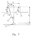
θi=Tan−1(W/2)/
Claims (16)
Applications Claiming Priority (3)
| Application Number | Priority Date | Filing Date | Title |
|---|---|---|---|
| TW97151500 | 2008-12-30 | ||
| TW97151500A | 2008-12-30 | ||
| TW097151500A TWI390475B (en) | 2008-12-30 | 2008-12-30 | Method for searching for a superior angle of incidence |
Publications (2)
| Publication Number | Publication Date |
|---|---|
| US20100165331A1 US20100165331A1 (en) | 2010-07-01 |
| US8325331B2 true US8325331B2 (en) | 2012-12-04 |
Family
ID=42284559
Family Applications (1)
| Application Number | Title | Priority Date | Filing Date |
|---|---|---|---|
| US12/568,173 Expired - Fee Related US8325331B2 (en) | 2008-12-30 | 2009-09-28 | Method for obtaining incident angle |
Country Status (2)
| Country | Link |
|---|---|
| US (1) | US8325331B2 (en) |
| TW (1) | TWI390475B (en) |
Citations (3)
| Publication number | Priority date | Publication date | Assignee | Title |
|---|---|---|---|---|
| US4803371A (en) * | 1987-09-30 | 1989-02-07 | The Coe Manufacturing Company | Optical scanning method and apparatus useful for determining the configuration of an object |
| CN2227369Y (en) | 1995-06-27 | 1996-05-15 | 宋桂源 | Stereo-advertisement lamp box |
| CN1683968A (en) | 2004-04-12 | 2005-10-19 | 株式会社可乐丽 | Lighting system, image display apparatus using the same and light diffusion plate used therefor |
-
2008
- 2008-12-30 TW TW097151500A patent/TWI390475B/en not_active IP Right Cessation
-
2009
- 2009-09-28 US US12/568,173 patent/US8325331B2/en not_active Expired - Fee Related
Patent Citations (5)
| Publication number | Priority date | Publication date | Assignee | Title |
|---|---|---|---|---|
| US4803371A (en) * | 1987-09-30 | 1989-02-07 | The Coe Manufacturing Company | Optical scanning method and apparatus useful for determining the configuration of an object |
| CN2227369Y (en) | 1995-06-27 | 1996-05-15 | 宋桂源 | Stereo-advertisement lamp box |
| CN1683968A (en) | 2004-04-12 | 2005-10-19 | 株式会社可乐丽 | Lighting system, image display apparatus using the same and light diffusion plate used therefor |
| US7237930B2 (en) * | 2004-04-12 | 2007-07-03 | Kuraray Co., Ltd. | Lighting system image display apparatus using the same and light diffusion plate used therefor |
| US7556393B2 (en) * | 2004-04-12 | 2009-07-07 | Kuraray Co., Ltd. | Lighting system, image display apparatus using the same and light diffusion plate used therefor |
Non-Patent Citations (1)
| Title |
|---|
| Office Action for Chinese Application No. 200910003093.2, dated May 9, 2011. |
Also Published As
| Publication number | Publication date |
|---|---|
| TW201025226A (en) | 2010-07-01 |
| TWI390475B (en) | 2013-03-21 |
| US20100165331A1 (en) | 2010-07-01 |
Similar Documents
| Publication | Publication Date | Title |
|---|---|---|
| JP6073415B2 (en) | Touch panel with fingerprint authentication function | |
| US20100156793A1 (en) | System and Method For An Information Handling System Touchscreen Keyboard | |
| US20160109636A1 (en) | Backlight module capable of avoiding light leakage | |
| TW201435672A (en) | Touch panel and method of manufacturing the same | |
| TW201432532A (en) | Touch panel and manufacturing method thereof and touch display panel | |
| WO2022228376A1 (en) | Message processing method and apparatus, and electronic device | |
| TW201621609A (en) | Method and system for displaying desktop | |
| US10354193B2 (en) | Run-time image display on a device | |
| TWI619050B (en) | Touch sensor | |
| US8325331B2 (en) | Method for obtaining incident angle | |
| CN111831064B (en) | Electronic device with luminous decorative strip | |
| US9557823B1 (en) | Keyboard customization according to finger positions | |
| US10614152B2 (en) | Exposing formatting properties of content for accessibility | |
| US20060267946A1 (en) | Methods and systems for providing feedback corresponding to user input | |
| CN203966912U (en) | The back lighting device of keyboard | |
| Cholewiak et al. | Distinguishing between texture and shading flows for 3D shape estimation | |
| Garmon et al. | Contextual influences on shape perception | |
| CN204257467U (en) | A kind of anti-key assembling structure of floating | |
| Liu et al. | Object stability is determined by the geometric centroid | |
| CN103677641A (en) | Information processing method and device | |
| Schönmann et al. | Using an Odd-One-Out Design Affects Consistency, Agreement and Decision Criteria in Similarity Judgement Tasks Involving Natural Images. | |
| BRPI1010765B1 (en) | Method implemented by a mobile communication device, computer readable medium and mobile communication device | |
| Li et al. | Generalized representation of shapes from different cues in parts of IPS areas | |
| CN101782683A (en) | Method for searching for angle of incidence | |
| Portley et al. | The second elbow in number perception |
Legal Events
| Date | Code | Title | Description |
|---|---|---|---|
| AS | Assignment |
Owner name: ARCADYAN TECHNOLOGY CORP.,TAIWAN Free format text: ASSIGNMENT OF ASSIGNORS INTEREST;ASSIGNORS:CHEN, SHENG CHUNG;WU, CHIN YI;REEL/FRAME:023291/0129 Effective date: 20090922 Owner name: ARCADYAN TECHNOLOGY CORP., TAIWAN Free format text: ASSIGNMENT OF ASSIGNORS INTEREST;ASSIGNORS:CHEN, SHENG CHUNG;WU, CHIN YI;REEL/FRAME:023291/0129 Effective date: 20090922 |
|
| STCF | Information on status: patent grant |
Free format text: PATENTED CASE |
|
| FPAY | Fee payment |
Year of fee payment: 4 |
|
| FEPP | Fee payment procedure |
Free format text: MAINTENANCE FEE REMINDER MAILED (ORIGINAL EVENT CODE: REM.); ENTITY STATUS OF PATENT OWNER: LARGE ENTITY |
|
| LAPS | Lapse for failure to pay maintenance fees |
Free format text: PATENT EXPIRED FOR FAILURE TO PAY MAINTENANCE FEES (ORIGINAL EVENT CODE: EXP.); ENTITY STATUS OF PATENT OWNER: LARGE ENTITY |
|
| STCH | Information on status: patent discontinuation |
Free format text: PATENT EXPIRED DUE TO NONPAYMENT OF MAINTENANCE FEES UNDER 37 CFR 1.362 |
|
| FP | Lapsed due to failure to pay maintenance fee |
Effective date: 20201204 |