US8325108B2 - System for controlling brightness flicker of parallax barrier LCD that has wide viewing angle and method thereof - Google Patents
System for controlling brightness flicker of parallax barrier LCD that has wide viewing angle and method thereof Download PDFInfo
- Publication number
- US8325108B2 US8325108B2 US12/829,868 US82986810A US8325108B2 US 8325108 B2 US8325108 B2 US 8325108B2 US 82986810 A US82986810 A US 82986810A US 8325108 B2 US8325108 B2 US 8325108B2
- Authority
- US
- United States
- Prior art keywords
- split
- viewer
- barrier electrodes
- viewing angle
- image
- Prior art date
- Legal status (The legal status is an assumption and is not a legal conclusion. Google has not performed a legal analysis and makes no representation as to the accuracy of the status listed.)
- Expired - Fee Related, expires
Links
Images


Classifications
-
- H—ELECTRICITY
- H04—ELECTRIC COMMUNICATION TECHNIQUE
- H04N—PICTORIAL COMMUNICATION, e.g. TELEVISION
- H04N13/00—Stereoscopic video systems; Multi-view video systems; Details thereof
-
- G—PHYSICS
- G09—EDUCATION; CRYPTOGRAPHY; DISPLAY; ADVERTISING; SEALS
- G09G—ARRANGEMENTS OR CIRCUITS FOR CONTROL OF INDICATING DEVICES USING STATIC MEANS TO PRESENT VARIABLE INFORMATION
- G09G3/00—Control arrangements or circuits, of interest only in connection with visual indicators other than cathode-ray tubes
- G09G3/20—Control arrangements or circuits, of interest only in connection with visual indicators other than cathode-ray tubes for presentation of an assembly of a number of characters, e.g. a page, by composing the assembly by combination of individual elements arranged in a matrix no fixed position being assigned to or needed to be assigned to the individual characters or partial characters
- G09G3/34—Control arrangements or circuits, of interest only in connection with visual indicators other than cathode-ray tubes for presentation of an assembly of a number of characters, e.g. a page, by composing the assembly by combination of individual elements arranged in a matrix no fixed position being assigned to or needed to be assigned to the individual characters or partial characters by control of light from an independent source
- G09G3/36—Control arrangements or circuits, of interest only in connection with visual indicators other than cathode-ray tubes for presentation of an assembly of a number of characters, e.g. a page, by composing the assembly by combination of individual elements arranged in a matrix no fixed position being assigned to or needed to be assigned to the individual characters or partial characters by control of light from an independent source using liquid crystals
-
- G—PHYSICS
- G02—OPTICS
- G02B—OPTICAL ELEMENTS, SYSTEMS OR APPARATUS
- G02B27/00—Optical systems or apparatus not provided for by any of the groups G02B1/00 - G02B26/00, G02B30/00
- G02B27/0093—Optical systems or apparatus not provided for by any of the groups G02B1/00 - G02B26/00, G02B30/00 with means for monitoring data relating to the user, e.g. head-tracking, eye-tracking
-
- G—PHYSICS
- G02—OPTICS
- G02B—OPTICAL ELEMENTS, SYSTEMS OR APPARATUS
- G02B30/00—Optical systems or apparatus for producing three-dimensional [3D] effects, e.g. stereoscopic images
- G02B30/20—Optical systems or apparatus for producing three-dimensional [3D] effects, e.g. stereoscopic images by providing first and second parallax images to an observer's left and right eyes
- G02B30/26—Optical systems or apparatus for producing three-dimensional [3D] effects, e.g. stereoscopic images by providing first and second parallax images to an observer's left and right eyes of the autostereoscopic type
- G02B30/27—Optical systems or apparatus for producing three-dimensional [3D] effects, e.g. stereoscopic images by providing first and second parallax images to an observer's left and right eyes of the autostereoscopic type involving lenticular arrays
-
- G—PHYSICS
- G02—OPTICS
- G02B—OPTICAL ELEMENTS, SYSTEMS OR APPARATUS
- G02B30/00—Optical systems or apparatus for producing three-dimensional [3D] effects, e.g. stereoscopic images
- G02B30/20—Optical systems or apparatus for producing three-dimensional [3D] effects, e.g. stereoscopic images by providing first and second parallax images to an observer's left and right eyes
- G02B30/26—Optical systems or apparatus for producing three-dimensional [3D] effects, e.g. stereoscopic images by providing first and second parallax images to an observer's left and right eyes of the autostereoscopic type
- G02B30/30—Optical systems or apparatus for producing three-dimensional [3D] effects, e.g. stereoscopic images by providing first and second parallax images to an observer's left and right eyes of the autostereoscopic type involving parallax barriers
-
- G—PHYSICS
- G02—OPTICS
- G02F—OPTICAL DEVICES OR ARRANGEMENTS FOR THE CONTROL OF LIGHT BY MODIFICATION OF THE OPTICAL PROPERTIES OF THE MEDIA OF THE ELEMENTS INVOLVED THEREIN; NON-LINEAR OPTICS; FREQUENCY-CHANGING OF LIGHT; OPTICAL LOGIC ELEMENTS; OPTICAL ANALOGUE/DIGITAL CONVERTERS
- G02F1/00—Devices or arrangements for the control of the intensity, colour, phase, polarisation or direction of light arriving from an independent light source, e.g. switching, gating or modulating; Non-linear optics
- G02F1/01—Devices or arrangements for the control of the intensity, colour, phase, polarisation or direction of light arriving from an independent light source, e.g. switching, gating or modulating; Non-linear optics for the control of the intensity, phase, polarisation or colour
- G02F1/13—Devices or arrangements for the control of the intensity, colour, phase, polarisation or direction of light arriving from an independent light source, e.g. switching, gating or modulating; Non-linear optics for the control of the intensity, phase, polarisation or colour based on liquid crystals, e.g. single liquid crystal display cells
- G02F1/133—Constructional arrangements; Operation of liquid crystal cells; Circuit arrangements
- G02F1/1333—Constructional arrangements; Manufacturing methods
- G02F1/1335—Structural association of cells with optical devices, e.g. polarisers or reflectors
-
- G—PHYSICS
- G02—OPTICS
- G02F—OPTICAL DEVICES OR ARRANGEMENTS FOR THE CONTROL OF LIGHT BY MODIFICATION OF THE OPTICAL PROPERTIES OF THE MEDIA OF THE ELEMENTS INVOLVED THEREIN; NON-LINEAR OPTICS; FREQUENCY-CHANGING OF LIGHT; OPTICAL LOGIC ELEMENTS; OPTICAL ANALOGUE/DIGITAL CONVERTERS
- G02F1/00—Devices or arrangements for the control of the intensity, colour, phase, polarisation or direction of light arriving from an independent light source, e.g. switching, gating or modulating; Non-linear optics
- G02F1/01—Devices or arrangements for the control of the intensity, colour, phase, polarisation or direction of light arriving from an independent light source, e.g. switching, gating or modulating; Non-linear optics for the control of the intensity, phase, polarisation or colour
- G02F1/13—Devices or arrangements for the control of the intensity, colour, phase, polarisation or direction of light arriving from an independent light source, e.g. switching, gating or modulating; Non-linear optics for the control of the intensity, phase, polarisation or colour based on liquid crystals, e.g. single liquid crystal display cells
- G02F1/133—Constructional arrangements; Operation of liquid crystal cells; Circuit arrangements
- G02F1/1333—Constructional arrangements; Manufacturing methods
- G02F1/1343—Electrodes
-
- G—PHYSICS
- G09—EDUCATION; CRYPTOGRAPHY; DISPLAY; ADVERTISING; SEALS
- G09G—ARRANGEMENTS OR CIRCUITS FOR CONTROL OF INDICATING DEVICES USING STATIC MEANS TO PRESENT VARIABLE INFORMATION
- G09G3/00—Control arrangements or circuits, of interest only in connection with visual indicators other than cathode-ray tubes
- G09G3/001—Control arrangements or circuits, of interest only in connection with visual indicators other than cathode-ray tubes using specific devices not provided for in groups G09G3/02 - G09G3/36, e.g. using an intermediate record carrier such as a film slide; Projection systems; Display of non-alphanumerical information, solely or in combination with alphanumerical information, e.g. digital display on projected diapositive as background
- G09G3/003—Control arrangements or circuits, of interest only in connection with visual indicators other than cathode-ray tubes using specific devices not provided for in groups G09G3/02 - G09G3/36, e.g. using an intermediate record carrier such as a film slide; Projection systems; Display of non-alphanumerical information, solely or in combination with alphanumerical information, e.g. digital display on projected diapositive as background to produce spatial visual effects
-
- G—PHYSICS
- G09—EDUCATION; CRYPTOGRAPHY; DISPLAY; ADVERTISING; SEALS
- G09G—ARRANGEMENTS OR CIRCUITS FOR CONTROL OF INDICATING DEVICES USING STATIC MEANS TO PRESENT VARIABLE INFORMATION
- G09G3/00—Control arrangements or circuits, of interest only in connection with visual indicators other than cathode-ray tubes
- G09G3/20—Control arrangements or circuits, of interest only in connection with visual indicators other than cathode-ray tubes for presentation of an assembly of a number of characters, e.g. a page, by composing the assembly by combination of individual elements arranged in a matrix no fixed position being assigned to or needed to be assigned to the individual characters or partial characters
-
- H—ELECTRICITY
- H04—ELECTRIC COMMUNICATION TECHNIQUE
- H04N—PICTORIAL COMMUNICATION, e.g. TELEVISION
- H04N13/00—Stereoscopic video systems; Multi-view video systems; Details thereof
- H04N13/30—Image reproducers
- H04N13/302—Image reproducers for viewing without the aid of special glasses, i.e. using autostereoscopic displays
- H04N13/31—Image reproducers for viewing without the aid of special glasses, i.e. using autostereoscopic displays using parallax barriers
- H04N13/315—Image reproducers for viewing without the aid of special glasses, i.e. using autostereoscopic displays using parallax barriers the parallax barriers being time-variant
-
- H—ELECTRICITY
- H04—ELECTRIC COMMUNICATION TECHNIQUE
- H04N—PICTORIAL COMMUNICATION, e.g. TELEVISION
- H04N13/00—Stereoscopic video systems; Multi-view video systems; Details thereof
- H04N13/30—Image reproducers
- H04N13/366—Image reproducers using viewer tracking
- H04N13/376—Image reproducers using viewer tracking for tracking left-right translational head movements, i.e. lateral movements
-
- G—PHYSICS
- G09—EDUCATION; CRYPTOGRAPHY; DISPLAY; ADVERTISING; SEALS
- G09G—ARRANGEMENTS OR CIRCUITS FOR CONTROL OF INDICATING DEVICES USING STATIC MEANS TO PRESENT VARIABLE INFORMATION
- G09G2320/00—Control of display operating conditions
- G09G2320/02—Improving the quality of display appearance
- G09G2320/0247—Flicker reduction other than flicker reduction circuits used for single beam cathode-ray tubes
-
- G—PHYSICS
- G09—EDUCATION; CRYPTOGRAPHY; DISPLAY; ADVERTISING; SEALS
- G09G—ARRANGEMENTS OR CIRCUITS FOR CONTROL OF INDICATING DEVICES USING STATIC MEANS TO PRESENT VARIABLE INFORMATION
- G09G2354/00—Aspects of interface with display user
-
- G—PHYSICS
- G09—EDUCATION; CRYPTOGRAPHY; DISPLAY; ADVERTISING; SEALS
- G09G—ARRANGEMENTS OR CIRCUITS FOR CONTROL OF INDICATING DEVICES USING STATIC MEANS TO PRESENT VARIABLE INFORMATION
- G09G2356/00—Detection of the display position w.r.t. other display screens
Definitions
- the present invention relates to a parallax barrier LCD, and more particularly, to a system for controlling brightness flicker of a parallax barrier LCD having a wide viewing angle that is capable of minimizing the brightness flicker by adjusting a permittivity curve depending on different times into a predetermined waveform when split barriers are on/off by movement of a viewer's viewing angle, and a method thereof.
- One of representative methods allows a viewer to acquire a cubic effect by installing a lenticular lens or a parallax barrier spaced by a predetermine distance on a 2D image panel to cause different image information to be transmitted to a viewer's left and right eyes.
- left and right images are arranged on a focus surface of a lens called a semi-cylindrical lenticular screen in a stripe pattern, and the left and right images are split depending on the directionality of a lens plate through the lens to allow the viewer to view a stereoscopic image without glasses.
- the width of one lens is determined by a pixel width of a display device.
- Two pixels respectively corresponding to the left and right eyes are provided to allow a pixel at the left side of the lens to be viewed by only a right eye and a pixel at the right side of the lens to be viewed by only a left eye, thereby splitting the left and right images.
- thin stripe vertical slits for transmitting or shielding light are arranged between a viewer's eye and an image at a regular interval and left and right images are alternately disposed at the front or back of the slits by an appropriate interval, and as a result, the left and right images are optically split when the image is viewed through the slit at a predetermined location, causing the viewer to acquire the cubic effect.
- a stripe parallax barrier optical plate serving as special glasses is installed in front of a monitor screen to allow the viewer to recognize the stereoscopic image without wearing the glasses.
- the stereoscopic display technology adopts the method using the binocular disparity.
- FIG. 1 is a diagram showing a concept of a known stereoscopic display, which is disclosed in U.S. Pat. No. 6,108,029.
- the stereoscopic display is configured by installing a parallax barrier 12 in the rear of an image display panel 11 by a predetermined distance.
- a left image L and a right image R are alternately arranged with a pixel pitch P
- a transparent part 12 a and an opaque part 12 b are alternately arranged with a barrier pitch q.
- Light emitted from a light source passes through the transparent part 12 a of the parallax barrier 12 and reaches both eyes RE and LE of a viewer through the image display panel 11 .
- a light source not shown
- Light that passes through the right image R of the image display panel 11 reaches the right eye RE of the viewer and light that passes though the left image L of the image display panel 11 reaches the left eye LE of the viewer.
- the left image L and the right image R of the image display panel 11 are inputted into the left and right eyes RE and LE of the viewer as different 2D image information to allow the viewer to acquire image information having a cubic effect.
- the parallax barrier 12 is installed in the rear of the image display panel 11 , but the image display panel 11 may be installed in the rear of the parallax barrier 12 .
- the stereoscopic display may display both the planar image and the stereoscopic image by adjusting the opaque part of the parallax barrier 12 .
- Equation 1 d (2 n+ 1) P ( D+d )/ S,q 2 P ( D+d )/ D d (2 n+ 1) P ( D+d )/ S,q 2 P ( D+d )/ D (Equation 1)
- n a positive integer
- S represents a distance between the left and right eyes of the viewer
- D represents the shortest distance between the image display panel and the viewer's eye
- d represents the shortest distance between the parallax barrier and the image display panel
- q represents the barrier pitch of the parallax barrier
- P represents the pixel pitch of the image display panel.
- FIG. 2 is diagram showing a parallax barrier applied to a known stereoscopic display.
- the parallax barrier applied to the stereoscopic display includes a common electrode 21 of an upper plate or a lower plate, strip electrodes 22 of an opposite plate arranged at a regular interval of a barrier pitch q, and a power supply device 23 adjusting a transparent state and an opaque state by inducing rearrangement of a liquid crystal layer positioned between the common electrode 21 and the strip electrode 22 by supplying power to the common electrode 21 and the strip electrode 22 .
- FIGS. 3 and 4 are diagrams for describing disadvantages generated in a known stereoscopic display.
- the stereoscopic display allows the right eye RE of the viewer to view a right image R of an image display panel 31 and the left eye LE of the viewer to view a left image L of the image display panel 31 by actuating a parallax barrier 32 . Therefore, the viewer acquires the cubic effect by synthesizing two images viewed to the right eye RE and the left eye LE in the brain of the viewer.
- the parallax barrier 32 when a viewing angle of the viewer deviates from a predetermined location, a part of an image is covered by the barrier, and as a result, the stereoscopic image is not implemented.
- the viewing angle of the viewer moves from locations of RE and LE to locations of RE′ and LE′, a part of the image is covered by the parallax barrier 32 , and as a result, the parallax barrier 32 should be moved by W in order to maintain a stable stereoscopic image.
- FIG. 5 is a diagram showing movement of a barrier by a change of a viewing angle of a viewer in a stereoscopic display adopting a known split barrier scheme.
- the barrier is moved by appropriately combining and driving 8 split fine electrodes depending on the viewing angle of the viewer.
- the parallax barrier is moved by actuating the resulting split fine electrodes, thereby providing a stable stereoscopic image of which distortion is not generated at the moved viewing angle of the viewer.
- FIG. 6 is a diagram showing an on/off relationship of split barriers depending on movement of a viewing angle of a viewer in a known stereoscopic display.
- an on/off operation of a bundle of 6 split barriers is as shown in FIG. 6 .
- a split barrier that is turned off and a split barrier that is turned on have different permittivity characteristics, and as a result, the brightness flicker occurs at a region where ON and OFF intersect each other as shown in “A” of FIG. 7 .
- the brightness flicker occurs due to moire of the viewing angle of the viewer.
- the brightness flicker that occurs due to the on/off operation of the split barriers or the moire of the viewing angle of the viewer offends the eyes of the viewer at the time when the viewer views the stereoscopic image, and as a result, the viewer can view a comfortable stereoscopic image only by solving the brightness flicker.
- the present invention has been made in an effort to provide a system for controlling brightness flicker of a parallax barrier LCD having a wide viewing angle, having an advantage of minimizing occurrence of the brightness flicker by adjusting a permittivity curve through controlling a voltage applied to each electrode (cell) of a display panel in order to display an image.
- the present invention has been made in an effort to provide a system for controlling brightness flicker of a parallax barrier LCD having a wide viewing angle having another advantage of minimizing occurrence of the brightness flicker by adjusting the permittivity curve through splitting a permittivity curve depending on an “ON” state or a permittivity curve depending on an “OFF” state of the voltage applied to each electrode (cell) of the display panel by time, and applying a voltage waveform of a modulated phase depending on the shape of the split permittivity curve in order to display the image.
- the present invention has been made in an effort to provide a system for controlling brightness flicker of a parallax barrier LCD having a wide viewing angle having yet another advantage of minimizing occurrence of the brightness flicker caused due to moire as the viewer's viewing angle moves by adjusting the brightness of the barrier through separately driving the split barrier electrodes.
- the present invention has been made in an effort to provide a system for controlling brightness flicker of a parallax barrier LCD having a wide viewing angle having still another advantage of minimizing occurrence of the brightness flicker caused due to moire by applying a factor value depending on movement velocity of the viewer's viewing angle.
- an image input section installed at a predetermined portion of a display panel to acquire a real-time image of a viewer; a controller recognizing an image of the viewer and extracting locations and coordinates of eyes of a viewer, and controlling all operations of a stereoscopic image display depending on a change of a viewing angle of the viewer; and split barrier electrodes turned on/off depending on the control by the controller to implement a stereoscopic image,
- controller removes the brightness flicker by adjusting a permittivity characteristic depending on turn-on of split barriers by applying a predetermined set voltage to the split barrier electrodes.
- an image input section installed at a predetermined portion of a display panel to acquire a real-time image of a viewer; a controller recognizing an image of the viewer and extracting locations and coordinates of eyes of a viewer, and controlling all operations of a stereoscopic image display depending on a change of a viewing angle of the viewer; and split barrier electrodes turned on/off depending on the control by the controller to implement a stereoscopic image,
- controller splits and sets one or more curvature points on a permittivity curve by time while turning on/off the split barrier electrodes and supplies a voltage having a modulated phase to each curvature point to remove the brightness flicker.
- an image input section installed at a predetermined portion of a display panel to acquire a real-time image of a viewer; a controller recognizing the image of the viewer and extracting locations and coordinates of eyes of the viewer, and controlling all operations of a stereoscopic image display depending on a change of a viewing angle of the viewer; and split barrier electrodes turned on/off depending on the control by the controller to implement a stereoscopic image,
- controller controls the split barrier electrodes for each independent electrode while split barriers are moved and supplies one or more different voltages to the independent electrodes to remove the occurrence of the brightness flicker between adjacent electrodes.
- an image input section installed at a predetermined portion of a display panel to acquire a real-time image of a viewer; a controller recognizing the image of the viewer and extracting locations and coordinates of eyes of the viewer, and controlling all operations of a stereoscopic image display depending on a change of a viewing angle of the viewer; and split barrier electrodes turned on/off depending on the control by the controller to implement a stereoscopic image,
- control unit controls on/off timings of the split barrier electrodes that are turned on and the split barrier electrodes that are turned off to be different from each other while split barriers are moved to adjust a permittivity characteristic.
- an image input section installed at a predetermined portion of a display panel to acquire a real-time image of a viewer; a controller recognizing the image of the viewer and extracting locations and coordinates of eyes of the viewer, and controlling all operations of a stereoscopic image display depending on a change of a viewing angle of the viewer; and split barrier electrodes turned on/off depending on the control by the controller to implement a stereoscopic image,
- controller determines a movement velocity when the change of the viewing angle of the viewer is detected, and controls movement of the split barrier electrodes by applying a set factor value only when the movement velocity is lower than a threshold velocity and does not move the split barrier electrodes when the movement velocity is equal to or higher than the threshold velocity.
- Yet another embodiment of the present invention provides a method of controlling brightness flicker of a parallax barrier LCD having a wide viewing angle for controlling brightness of a display providing a stereoscopic image by acquiring a real-time image of a viewer, recognizing the image of the viewer and extracting locations and coordinates of eyes of the viewer, and controlling turn-on/off of split barrier electrodes, including at least one of:
- controlling movement of the split barrier electrodes by applying a set factor value only when a changing velocity of a viewing angle of the viewer is lower than a threshold velocity and not moving the split barrier electrodes when the changing velocity is equal to or higher than the threshold velocity.
- FIG. 1 is a diagram showing a concept of a known stereoscopic display
- FIG. 2 is diagram showing a parallax barrier applied to a known stereoscopic display
- FIGS. 3 and 4 are diagrams for describing disadvantages generated in a known stereoscopic display
- FIG. 5 is a diagram showing movement of a barrier by a change of a viewing angle of a viewer in a known stereoscopic display
- FIG. 6 is a diagram of an on/off relationship of split barriers depending on movement of a viewing angle of a viewer in a known stereoscopic display
- FIG. 7 is a diagram showing brightness flicker generated by movement of a barrier in a known stereoscopic display
- FIG. 8 is a diagram showing a brightness flicker phenomenon caused due to moire of a viewing angle of a viewer in a known stereoscopic display
- FIG. 9 is a diagram showing a schematic configuration of a system for controlling brightness flicker of a parallax barrier LCD having a wide viewing angle according to an exemplary embodiment of the present invention.
- FIGS. 10 and 11 are graphs showing one example of brightness flicker generated depending on an applied voltage in a stereoscopic display
- FIG. 12 is a graph showing an example in which brightness flicker depending on each applied voltage supplied to a display panel in a stereoscopic display is studied;
- FIG. 13 is a diagram showing improvement of brightness flicker by phase modulation in a system for controlling brightness flicker of a parallax barrier LCD having a wide viewing angle according to an exemplary embodiment of the present invention
- FIG. 14 is a diagram showing a control of phase modulation in a system for controlling brightness flicker of a parallax barrier LCD having a wide viewing angle according to an exemplary embodiment of the present invention
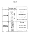
- FIG. 15 is a diagram showing control of independent driving of split barriers in a system for controlling brightness flicker of a parallax barrier LCD having a wide viewing angle according to an exemplary embodiment of the present invention
- FIG. 16 is a conceptual diagram showing correction adaptation depending on a changing velocity of a viewing angle of a viewer in a system for controlling brightness flicker of a parallax barrier LCD having a wide viewing angle according to an exemplary embodiment of the present invention.
- FIG. 17 is a conceptual diagram showing minimization of brightness flicker by controlling on/off timings of split barrier electrodes to be different from each other in a system for controlling brightness flicker of a parallax barrier LCD having a wide viewing angle according to an exemplary embodiment of the present invention.
- FIG. 9 is a diagram showing a schematic configuration of a system for controlling brightness flicker of a parallax barrier LCD having a wide viewing angle according to an exemplary embodiment of the present invention.
- the system includes an image input section 101 , a controller 102 , a driver 103 , and split barrier electrodes 104 .
- the image input section 101 is constituted by a camera installed at a predetermined location, preferably at the upper center of a display panel formed of a liquid crystal display device, and acquires a real-time image of a viewer who views a stereoscopic image and applies it to the controller 102 .
- the controller 102 recognizes and processes the real-time image of the viewer applied from the image input section 101 to extract locations and coordinates of eyes of the viewer and a changed coordinate of a viewing angle by movement of the viewer, thereby controlling movement of split barriers in order to provide a stable stereoscopic image.
- the controller 102 applies a predetermined set voltage to the split barrier electrode 104 through the driver 103 as the stereoscopic image is displayed, and adjusts permittivity characteristics of split barriers that are turned on to thereby minimize the brightness flicker.
- the controller 102 splits a permittivity curve depending on turn-on or a permittivity curve depending on turn-off by time while the split barrier electrodes 104 are turned on/off through the driver 103 as the stereoscopic image is displayed, and applies an appropriate waveform through phase modulation for each step to thereby prevent the brightness flicker from occurring at the time of the on/off operation depending on movement of the split barriers.
- the controller 102 may select and use any one of adjusting the permittivity curve depending on turn-on of the split barrier electrodes 104 and adjusting the permittivity curve depending on turn-off of the split barrier electrode 104 in order to minimize the brightness flicker by applying the phase-modulated waveform, and in addition, the controller 102 may adjust the permittivity curves depending on both turn-on and turn-off.
- the controller 102 splits the permittivity curves depending on turn-on and turn-off of the split barrier electrode 104 through the driver 103 by time to generate several curvature points, and applies an appropriate waveform to each of the curvature points through phase modulation.
- the controller 102 when the controller 102 detects a change of the viewing angle at the time of analyzing the image of the viewer who views the stereoscopic image, the controller 102 minimizes the brightness flicker through brightness correction by adding one or more intermediate steps and driving fine split barrier electrodes in order to correct brightness that is decreased while changing the split barriers.
- the controller 102 determines movement velocity and applies a factor depending on the velocity to control the on/off voltage of the split barrier electrodes 104 , thereby minimizing the brightness flicker.
- controller 102 controls on/off timings of the split barrier electrodes 104 that are turned on and the split barrier electrodes 104 that are turned off to be different from each other while moving the split barriers by controlling turn on/off of the split barrier electrodes 104 through the driver 103 so as to minimize the brightness flicker.
- voltage application timing of the split barrier electrodes 104 that are turned on is normally controlled and voltage elimination timing of the split barrier electrodes 104 that are turned off is controlled to be delayed by a predetermined time, or the voltage application timing of the split barrier electrodes 104 that are turned on is controlled to be earlier than the normal voltage application timing and the voltage elimination timing of the split barrier electrodes 104 that are turned off is normally controlled so as to minimize the brightness flicker through brightness correction.
- the split barrier electrodes 104 that are turned on are actuated earlier than the split barrier electrodes 104 that are turned off by a predetermined time.
- the driver 103 turns on/off the split barrier electrodes 104 by generating a patternized waveform depending on the control signal applied from the controller 102 to provide the stereoscopic image to the viewer through the display panel.
- the split barrier electrodes 104 are turned on/off depending on the waveform applied from the driver 103 to implement the stereoscopic image through the display panel.
- the display panel formed of the liquid crystal display device maintains a balance state even when a driving voltage is not applied to the electrode (cell), but when the driving voltage is applied to the electrode (cell), alignment of liquid crystals is changed depending on the voltage to display an image by using the resulting change of a polarization state. On the contrary, when the driving voltage applied to each electrode (cell) is eliminated, the display panel is restored to the original balance state.
- FIGS. 10 and 11 are graphs showing one example in which brightness flicker generated depending on driving voltage in a stereoscopic display is detected
- FIG. 12 as an experimental example of the present invention is a graph showing an example in which brightness flicker depending on each driving voltage in a stereoscopic display is studied.
- FIG. 10 shows a result of measuring characteristics of brightness while the split barrier electrodes 104 are turned on/off with a voltage of 3.3V through the driver 103 by the controller 102 in order to display the stereoscopic image.
- a characteristic in which brightness is increased and then restored to a normal state at a cross point where split barrier electrodes 104 are turned on and off is detected.
- FIG. 11 shows a result of measuring characteristics of brightness while the split barrier electrodes 104 are turned on/off with a voltage of 4.0V through the driver 103 by the controller 102 in order to display the stereoscopic image.
- a characteristic in which brightness is decreased and then restored to the normal state at the cross point where the split barrier electrodes 104 are turned on and off is detected.
- FIG. 12 shows data acquired by measuring a change of brightness depending on the voltage applied to the split barrier electrodes by using a 7-inch mini-monitor as one example.
- a permittivity deviation is 6.1%
- the permittivity deviation is 2.2%
- the permittivity deviation is 1.4%
- the permittivity deviation is 1.5%
- the permittivity deviation is 2.1%
- the split barrier electrodes 104 are turned on/off with a voltage of 4.7V
- the permittivity deviation is 2.7%
- the split barrier electrodes 104 are turned on/off with a voltage of 5.0V
- the permittivity deviation is 6.1%
- the split barrier electrodes 104 are turned on/off with a voltage of 4.0V
- the permittivity deviation is 2.2%
- the split barrier electrodes 104 are turned on/off with a voltage of 4.2V
- the permittivity deviation is 1.4%
- the split barrier electrodes 104 are turned on/off with a voltage of 4.3V
- the permittivity deviation is 1.5%
- the voltage is used as the driving voltage.
- the permittivity deviation is the smallest at 1.4% in the case in which the split barrier electrode 104 are actuated with the voltage of 4.2V. Therefore, the voltage is determined as a voltage to minimize the brightness flicker.
- the brightness flicker may be minimized by using an independent driving scheme of the split barrier electrodes 104 .
- the controller 102 first actuates the split barrier electrodes 104 with the voltage of 4.2V showing the smallest permittivity deviation, and thereafter boosts the voltage to the voltage of 5.0V or by steps after the boosting of the voltage through the driver 103 so as to minimize the brightness flicker.
- the controller 102 splits the permittivity curve depending on turn-on of the split barrier electrodes 104 by time while turning on/off the split barrier electrodes 104 by controlling the voltage applied to the split barrier electrodes 104 through the driver 103 in order to display the stereoscopic image, and applies an appropriate waveform by modulating the phase of the voltage applied depending on each of split timings so as to minimize the brightness flicker.
- FIG. 13 is a diagram showing improvement of brightness flicker by phase modulation in a system for controlling brightness flicker of a parallax barrier LCD having a wide viewing angle according to an exemplary embodiment of the present invention
- FIG. 14 is a diagram showing control of phase modulation in a system for controlling brightness flicker of a parallax barrier LCD having a wide viewing angle according to an exemplary embodiment of the present invention.
- the controller 102 extracts various curvature points a to f by splitting the permittivity curve depending on turn-off of the split barrier electrodes 104 while controlling the split barrier electrodes 104 through the driver 103 in order to display the stereoscopic image by time, and thereafter applies different waveforms through modulation of the voltage applied at each curvature point.
- Extraction of the curvature points in the permittivity curve is determined by a program regardless of the number of curvature points. Assuming that the voltage is driven at a phase of 120 Hz when the number of curvature points a to f is determined to be 6 as shown in FIG. 13 , the permittivity curve is split by time of approximately 8.33 msec.
- Modulation of the phase of the voltage at each curvature point is determined by using a table showing predetermined permittivity and voltage characteristics.
- an adjustable curvature point is extracted in the middle of the first barrier No 1 that is switched from the “ON” state to the “OFF” state in accordance with the barrier movement command Com and voltages having different phases are applied by modulating the phase of the voltage at each curvature point, thereby implementing the brightness flicker generated like A 101 of FIG. 13 to the stable brightness flicker like B 101 .
- a third embodiment shows a method of minimizing brightness flicker caused due to moire depending on a viewing angle.
- the split barriers are not continuously changed but are changed in a stepwise fashion depending on the number of split barriers.
- the brightness is continuously changed as shown in FIG. 8 .
- the brightness flicker caused due to moire depends on design and characteristics of the display, brightness flicker of approximately 30% is substantially generated depending on the change of the viewing angle. Therefore, in the present invention, the brightness flicker is minimized by controlling independent driving of the split barrier electrodes as shown in FIG. 15 .
- one or more intermediate steps are provided while moving the split barriers to the right side or the left side in order to correct decreased brightness by changing the viewing angle of the viewer, thereby minimizing the brightness flicker.
- the split barriers are moved from X 1 to X 4 to X 2 to X 5 in order to correct the brightness in accordance with a movement coordinate.
- one or more intermediate steps are further included while the split barriers are moved from the split barriers of the bundle of X 1 to X 4 to the split barriers of the bundle of X 2 to X 5 so as to prevent a brightness deviation from being generated between adjacent split barriers.
- the control unit 102 enters an intermediate step 1 to supply a second voltage bV having a minimum brightness deviation to the first split barrier electrode X 1 that is switched from the “ON” state to the “OFF” state, supply the second voltage bV having the minimum brightness deviation to the fifth split barrier electrode X 5 that is switched from the “OFF” state to the “ON” state and the fourth split barrier electrode X 4 adjacent to the fifth split barrier electrode X 5 , and supply the normal voltage aV to the second split barrier electrode X 2 and the second split barrier electrode X 3 .
- the first voltage aV which provides the stable stereoscopic characteristic, is higher than the second voltage bV, and as a result, the brightness in the display panel when the first voltage aV is supplied is higher than that when the second voltage bV is supplied.
- the brightness deviation is decreased between the first split barrier electrode X 1 and the second split barrier electrode X 2 to thereby minimize the brightness flicker, and the brightness deviation is also decreased between the third split barrier electrode X 3 and the fourth split barrier electrode X 4 to thereby minimize the brightness flicker.
- the controller 102 enters an intermediate step 2 to switch the first split barrier electrode X 1 from the “ON” state to the “OFF” state by completely interrupting the voltage supplied to the first split barrier electrode X 1 , supply the second voltage bV to the second split barrier electrode X 2 , and supply the second voltage bV to the fifth split barrier electrode X 5 .
- controller 102 supplies the first voltage aV to the third split barrier electrode X 3 and the fourth split barrier electrode X 4 .
- the brightness deviation is decreased between the second split barrier electrode X 2 and the third split barrier electrode X 3 to thereby minimize the occurrence of the flicker, and the brightness deviation is decreased between the fourth split barrier electrode X 4 and the fifth split barrier electrode X 5 that is switched from the “OFF” state to the “ON” state to thereby minimize the occurrence of the flicker.
- the first voltage aV is supplied to the second split barrier electrode X 2 to the fifth barrier electrode X 5 that constitute one bundle, thereby achieving display ensuring the stable stereoscopic characteristic in the display panel.
- the intermediate step is constituted by a plurality of steps and as a result the voltage is partitioned, the brightness flicker between the split barrier electrodes is further minimized. Further, the brightness flicker is variable depending on a designer.
- the first voltage aV actuating the split barrier electrodes a voltage of 5V or more at which the display panel displays sufficient contrast is supplied, as the voltage at the intermediate steps 1 and 2, a voltage of 4.2V at which the brightness deviation is minimized is applied, and when movement of the split barrier electrode is completed, a voltage of 5V having the excellent stereoscopic characteristic is supplied, thereby minimizing the occurrence of the brightness flicker.
- a voltage (final voltage) having the excellent stereoscopic characteristic and a voltage (intermediate voltage) having the smallest brightness flicker are selected and applied through repeated tests.
- the number of split barrier electrodes controlled at the initial step and the intermediate step and the step after the movement is completed may the same or different for each step.
- a fourth embodiment shows a method of adopting a correction factor depending on a changing velocity of a viewing angle of a viewer.
- FIG. 16 is a conceptual diagram showing correction adaptation depending on a changing velocity of a viewing angle of a viewer in a system for controlling brightness flicker of a parallax barrier LCD having a wide viewing angle according to an exemplary embodiment of the present invention.
- the controller 102 controls the movement velocity of the viewing angle of the viewer by adjusting the voltage applied to the split barrier electrode 104 by adopting a factor value depending on the movement velocity, thereby minimizing the occurrence of the brightness flicker while the split barrier electrode 104 is moved.
- a fifth embodiment shows a method of minimizing brightness flicker by controlling on/off timings of split barrier electrodes to be different from each other.
- FIGS. 17A and 17B are conceptual diagrams showing minimization of brightness flicker by controlling on/off timings of split barrier electrodes to be different from each other in a system for controlling brightness flicker of a parallax barrier LCD having a wide viewing angle according to an exemplary embodiment of the present invention.
- the split barrier electrodes 104 are turned on and off by the driver 103 .
- the timing when the voltage is applied to the split barrier electrode 104 that is turned on is normally controlled and the timing when the voltage applied to the split barrier electrode 104 that is turned off is eliminated is controlled to be delayed for a predetermined time to compensate brightness between adjacent split barrier electrodes, thereby minimizing the occurrence of the brightness flicker.
- the timing when the voltage is applied to the split barrier electrode 104 that is turned on is controlled to be earlier than the normal timing by a predetermined time and the timing when the voltage is applied to the split barrier electrode 104 that is turned off is normally controlled to compensate the brightness between the adjacent split barrier electrodes, thereby minimizing the occurrence of the brightness flicker.
- the voltage is applied to the split barrier electrode 104 that is turned on to be turned on at a time t 1 and the voltage applied to the split barrier electrode 104 that is turned off is eliminated at a time t 2 to thereby minimize the brightness flicker.
- the “ON” operation is executed faster than the “OFF” operation by a predetermined set time while the split barrier electrode 104 is controlled to be turned on/off.
- the above-mentioned exemplary embodiment of the present invention is not implemented by only the device and method, but may be implemented by a program that can realize functions corresponding to components of the exemplary embodiment of the present invention or a recording medium in which the program is recorded.
Abstract
Description
d(2n+1)P(D+d)/S,q2P(D+d)/D
d(2n+1)P(D+d)/S,q2P(D+d)/D (Equation 1)
Claims (12)
Applications Claiming Priority (2)
| Application Number | Priority Date | Filing Date | Title |
|---|---|---|---|
| KR10-2009-0063087 | 2009-07-10 | ||
| KR1020090063087A KR101057098B1 (en) | 2009-07-10 | 2009-07-10 | Luminance flicker control apparatus and method for wide viewing angle stereoscopic display |
Publications (2)
| Publication Number | Publication Date |
|---|---|
| US20110006979A1 US20110006979A1 (en) | 2011-01-13 |
| US8325108B2 true US8325108B2 (en) | 2012-12-04 |
Family
ID=43427063
Family Applications (1)
| Application Number | Title | Priority Date | Filing Date |
|---|---|---|---|
| US12/829,868 Expired - Fee Related US8325108B2 (en) | 2009-07-10 | 2010-07-02 | System for controlling brightness flicker of parallax barrier LCD that has wide viewing angle and method thereof |
Country Status (3)
| Country | Link |
|---|---|
| US (1) | US8325108B2 (en) |
| JP (1) | JP2011018049A (en) |
| KR (1) | KR101057098B1 (en) |
Cited By (3)
| Publication number | Priority date | Publication date | Assignee | Title |
|---|---|---|---|---|
| US9508182B2 (en) | 2012-01-05 | 2016-11-29 | Samsung Display Co., Ltd. | Method of displaying 3D image and display apparatus for performing the method |
| US10809664B2 (en) | 2016-11-10 | 2020-10-20 | Samsung Electronics Co., Ltd. | Holographic display apparatus for providing expanded viewing window |
| US11143868B2 (en) | 2018-04-24 | 2021-10-12 | Samsung Electronics Co., Ltd. | 3-dimensional image display apparatus and method of providing expanded viewing window |
Families Citing this family (38)
| Publication number | Priority date | Publication date | Assignee | Title |
|---|---|---|---|---|
| JP5462672B2 (en) * | 2010-03-16 | 2014-04-02 | 株式会社ジャパンディスプレイ | Display device and electronic device |
| JP5632764B2 (en) * | 2011-02-02 | 2014-11-26 | セイコーインスツル株式会社 | Stereoscopic image display device |
| JP5010746B1 (en) * | 2011-02-25 | 2012-08-29 | 株式会社東芝 | Image display device |
| US8534900B2 (en) | 2011-03-25 | 2013-09-17 | Unipixel Displays, Inc. | Interleaved lighting system for 2D-3D display having orthogonally arranged light extraction features |
| WO2012137879A1 (en) | 2011-04-08 | 2012-10-11 | シャープ株式会社 | Display device |
| US9036013B2 (en) | 2011-06-20 | 2015-05-19 | Electronics And Telecommunications Research Institute | Segmented dual layer parallax barrier-based 3D display device and method |
| US8988411B2 (en) * | 2011-07-08 | 2015-03-24 | Semiconductor Energy Laboratory Co., Ltd. | Display device |
| JP5562298B2 (en) * | 2011-07-19 | 2014-07-30 | 三菱電機株式会社 | Display device |
| KR101214719B1 (en) * | 2011-09-30 | 2012-12-21 | 삼성전기주식회사 | Barrier pannel, apparatus and method for displaying 3d image |
| KR101896695B1 (en) | 2011-10-05 | 2018-09-10 | 한국전자통신연구원 | Stereo-scopic image panel, stereo-scopic image display apparatus having the same and driving method thereof |
| US20130093753A1 (en) * | 2011-10-14 | 2013-04-18 | Nokia Corporation | Auto-stereoscopic display control |
| CN103163650A (en) * | 2011-12-08 | 2013-06-19 | 武汉天马微电子有限公司 | Naked eye three-dimensional (3D) grating structure |
| KR20130072502A (en) * | 2011-12-22 | 2013-07-02 | 삼성디스플레이 주식회사 | Parallax barrier panel and display apparatus having the same |
| KR101572406B1 (en) * | 2012-02-15 | 2015-11-26 | 샤프 가부시키가이샤 | Three-dimensional display device |
| GB2499426A (en) * | 2012-02-16 | 2013-08-21 | Dimenco B V | Autostereoscopic display device with viewer tracking system |
| WO2013125466A1 (en) * | 2012-02-21 | 2013-08-29 | シャープ株式会社 | Display device |
| JP5907758B2 (en) * | 2012-03-02 | 2016-04-26 | 株式会社ジャパンディスプレイ | Display device and liquid crystal barrier element |
| JP5805566B2 (en) * | 2012-03-22 | 2015-11-04 | セイコーインスツル株式会社 | Barrier liquid crystal device and stereoscopic image display device |
| KR101958447B1 (en) | 2012-05-16 | 2019-03-15 | 삼성디스플레이 주식회사 | 3 dimensional image display device and driving method thereof |
| CN102662283B (en) * | 2012-05-25 | 2015-04-29 | 天马微电子股份有限公司 | Liquid-crystal slit grating, stereoscopic display device and calibration method of stereoscopic display device |
| KR101983248B1 (en) * | 2012-06-13 | 2019-05-29 | 삼성디스플레이 주식회사 | Method of driving a display panel, display panel driving apparatus for performing the method and display apparatus having the display panel driving apparatus |
| JP6213812B2 (en) * | 2012-07-31 | 2017-10-18 | Tianma Japan株式会社 | Stereoscopic image display apparatus and stereoscopic image processing method |
| CN102798982B (en) | 2012-08-31 | 2015-11-25 | 深圳超多维光电子有限公司 | A kind of stereoscopic display device and stereo display control method |
| JP5910470B2 (en) * | 2012-11-21 | 2016-04-27 | 三菱電機株式会社 | Display device and driving method thereof |
| WO2014141813A1 (en) * | 2013-03-11 | 2014-09-18 | シャープ株式会社 | Stereoscopic display device |
| KR101981530B1 (en) * | 2013-03-29 | 2019-05-23 | 엘지디스플레이 주식회사 | Stereoscopic image display device and method for driving the same |
| TWI489148B (en) * | 2013-08-23 | 2015-06-21 | Au Optronics Corp | Stereoscopic display and the driving method |
| KR102142250B1 (en) * | 2013-08-30 | 2020-08-07 | 엘지디스플레이 주식회사 | 3-dimension image display device and driving method thereof |
| KR102174898B1 (en) * | 2013-12-19 | 2020-11-06 | 삼성디스플레이 주식회사 | Method of driving a display panel, display panel driving apparatus performing the method and display apparatus having the display panel driving apparatus |
| JP6076893B2 (en) * | 2013-12-27 | 2017-02-08 | 株式会社ジャパンディスプレイ | Display device and manufacturing method of display device |
| US9843792B2 (en) * | 2014-04-02 | 2017-12-12 | Telefonaktiebolaget L M Ericsson (Publ) | Multi-view display control |
| KR101658629B1 (en) * | 2014-05-02 | 2016-09-22 | 삼성전자주식회사 | Dispaly apparatus and controlling method thereof |
| GB2540376A (en) * | 2015-07-14 | 2017-01-18 | Sharp Kk | Parallax barrier with independently controllable regions |
| GB2540377A (en) | 2015-07-14 | 2017-01-18 | Sharp Kk | Parallax barrier with independently controllable regions |
| JP6848043B2 (en) * | 2016-08-08 | 2021-03-24 | 昆山龍騰光電有限公司 | Liquid crystal display device that can switch the viewing angle and its viewing angle switching method |
| JP7336782B2 (en) * | 2018-12-21 | 2023-09-01 | 公立大学法人大阪 | 3D display device, 3D display system, head-up display, and moving object |
| JP7228033B2 (en) * | 2019-05-30 | 2023-02-22 | 京セラ株式会社 | 3D display device, head-up display system, and moving body |
| CN114173108B (en) * | 2021-09-30 | 2023-12-12 | 合肥京东方光电科技有限公司 | Control method and device of 3D display panel, computer equipment and storage medium |
Citations (23)
| Publication number | Priority date | Publication date | Assignee | Title |
|---|---|---|---|---|
| US4847603A (en) * | 1986-05-01 | 1989-07-11 | Blanchard Clark E | Automatic closed loop scaling and drift correcting system and method particularly for aircraft head up displays |
| US5671007A (en) * | 1994-03-28 | 1997-09-23 | Magma, Inc. | Two-dimensional and three-dimensional imaging device with improved light valve and field rate |
| US5907364A (en) * | 1995-05-29 | 1999-05-25 | Hitachi, Ltd. | Display device for information signals |
| US6108029A (en) | 1997-08-22 | 2000-08-22 | Lo; Allen Kwok Wah | Dual-mode 2D/3D display system |
| US6307589B1 (en) * | 1993-01-07 | 2001-10-23 | Francis J. Maquire, Jr. | Head mounted camera with eye monitor and stereo embodiments thereof |
| US6377295B1 (en) * | 1996-09-12 | 2002-04-23 | Sharp Kabushiki Kaisha | Observer tracking directional display |
| US20030025995A1 (en) * | 2001-07-27 | 2003-02-06 | Peter-Andre Redert | Autostereoscopie |
| US20030076423A1 (en) * | 1991-02-21 | 2003-04-24 | Eugene Dolgoff | Optical element to reshape light with color and brightness uniformity |
| US20030118183A1 (en) * | 2001-08-03 | 2003-06-26 | Struyk David A. | Image altering apparatus and method for providing confidential viewing of a fundamental display image |
| US20030169213A1 (en) * | 2002-03-07 | 2003-09-11 | Spero Yechezkal Evan | Enhanced vision for driving |
| US6727866B2 (en) * | 2001-05-31 | 2004-04-27 | Industrial Technology Research Institute | Parallax barrier type autostereoscopic display device |
| US6778150B1 (en) * | 1993-09-14 | 2004-08-17 | Francis J. Maguire, Jr. | Method and apparatus for eye tracking |
| US6953249B1 (en) * | 2001-01-29 | 2005-10-11 | Maguire Jr Francis J | Method and devices for displaying images for viewing with varying accommodation |
| KR20060096844A (en) | 2005-03-04 | 2006-09-13 | 주식회사 소디 | Variable parallax barrier and 3d image display device using the barrier |
| KR20070023849A (en) | 2005-08-25 | 2007-03-02 | (주)엔디스 | Parallax barrier lcd which has wide viewing angle |
| KR100765131B1 (en) | 2006-05-12 | 2007-10-22 | (주)엔디스 | Parallax barrier lcd which has wide viewing angle |
| KR20080056592A (en) | 2006-12-18 | 2008-06-23 | 삼성전자주식회사 | Auto stereoscopic display |
| US20080258997A1 (en) * | 2007-04-18 | 2008-10-23 | Seiko Epson Corporation | Display device, method of driving display device, and electronic apparatus |
| US20090085912A1 (en) * | 2007-10-01 | 2009-04-02 | Scott Miles L | Full-Color Anaglyph Three-Dimensional Display |
| US20100002295A1 (en) * | 2008-07-01 | 2010-01-07 | Tom Kimpe | Methods and systems for stereoscopic imaging |
| US7688509B2 (en) * | 2003-02-21 | 2010-03-30 | Koninklijke Philips Electronics N.V. | Autostereoscopic display |
| US7864419B2 (en) * | 2004-06-08 | 2011-01-04 | Ellis Amalgamated LLC | Optical scanning assembly |
| US8013944B2 (en) * | 2004-10-25 | 2011-09-06 | Koninklijke Philips Electronics N.V. | Display device for reducing cross-talk between displayed images |
-
2009
- 2009-07-10 KR KR1020090063087A patent/KR101057098B1/en active IP Right Grant
-
2010
- 2010-07-02 US US12/829,868 patent/US8325108B2/en not_active Expired - Fee Related
- 2010-07-12 JP JP2010158236A patent/JP2011018049A/en active Pending
Patent Citations (23)
| Publication number | Priority date | Publication date | Assignee | Title |
|---|---|---|---|---|
| US4847603A (en) * | 1986-05-01 | 1989-07-11 | Blanchard Clark E | Automatic closed loop scaling and drift correcting system and method particularly for aircraft head up displays |
| US20030076423A1 (en) * | 1991-02-21 | 2003-04-24 | Eugene Dolgoff | Optical element to reshape light with color and brightness uniformity |
| US6307589B1 (en) * | 1993-01-07 | 2001-10-23 | Francis J. Maquire, Jr. | Head mounted camera with eye monitor and stereo embodiments thereof |
| US6778150B1 (en) * | 1993-09-14 | 2004-08-17 | Francis J. Maguire, Jr. | Method and apparatus for eye tracking |
| US5671007A (en) * | 1994-03-28 | 1997-09-23 | Magma, Inc. | Two-dimensional and three-dimensional imaging device with improved light valve and field rate |
| US5907364A (en) * | 1995-05-29 | 1999-05-25 | Hitachi, Ltd. | Display device for information signals |
| US6377295B1 (en) * | 1996-09-12 | 2002-04-23 | Sharp Kabushiki Kaisha | Observer tracking directional display |
| US6108029A (en) | 1997-08-22 | 2000-08-22 | Lo; Allen Kwok Wah | Dual-mode 2D/3D display system |
| US6953249B1 (en) * | 2001-01-29 | 2005-10-11 | Maguire Jr Francis J | Method and devices for displaying images for viewing with varying accommodation |
| US6727866B2 (en) * | 2001-05-31 | 2004-04-27 | Industrial Technology Research Institute | Parallax barrier type autostereoscopic display device |
| US20030025995A1 (en) * | 2001-07-27 | 2003-02-06 | Peter-Andre Redert | Autostereoscopie |
| US20030118183A1 (en) * | 2001-08-03 | 2003-06-26 | Struyk David A. | Image altering apparatus and method for providing confidential viewing of a fundamental display image |
| US20030169213A1 (en) * | 2002-03-07 | 2003-09-11 | Spero Yechezkal Evan | Enhanced vision for driving |
| US7688509B2 (en) * | 2003-02-21 | 2010-03-30 | Koninklijke Philips Electronics N.V. | Autostereoscopic display |
| US7864419B2 (en) * | 2004-06-08 | 2011-01-04 | Ellis Amalgamated LLC | Optical scanning assembly |
| US8013944B2 (en) * | 2004-10-25 | 2011-09-06 | Koninklijke Philips Electronics N.V. | Display device for reducing cross-talk between displayed images |
| KR20060096844A (en) | 2005-03-04 | 2006-09-13 | 주식회사 소디 | Variable parallax barrier and 3d image display device using the barrier |
| KR20070023849A (en) | 2005-08-25 | 2007-03-02 | (주)엔디스 | Parallax barrier lcd which has wide viewing angle |
| KR100765131B1 (en) | 2006-05-12 | 2007-10-22 | (주)엔디스 | Parallax barrier lcd which has wide viewing angle |
| KR20080056592A (en) | 2006-12-18 | 2008-06-23 | 삼성전자주식회사 | Auto stereoscopic display |
| US20080258997A1 (en) * | 2007-04-18 | 2008-10-23 | Seiko Epson Corporation | Display device, method of driving display device, and electronic apparatus |
| US20090085912A1 (en) * | 2007-10-01 | 2009-04-02 | Scott Miles L | Full-Color Anaglyph Three-Dimensional Display |
| US20100002295A1 (en) * | 2008-07-01 | 2010-01-07 | Tom Kimpe | Methods and systems for stereoscopic imaging |
Cited By (4)
| Publication number | Priority date | Publication date | Assignee | Title |
|---|---|---|---|---|
| US9508182B2 (en) | 2012-01-05 | 2016-11-29 | Samsung Display Co., Ltd. | Method of displaying 3D image and display apparatus for performing the method |
| US10809664B2 (en) | 2016-11-10 | 2020-10-20 | Samsung Electronics Co., Ltd. | Holographic display apparatus for providing expanded viewing window |
| US11143868B2 (en) | 2018-04-24 | 2021-10-12 | Samsung Electronics Co., Ltd. | 3-dimensional image display apparatus and method of providing expanded viewing window |
| US11768380B2 (en) | 2018-04-24 | 2023-09-26 | Samsung Electronics Co., Ltd. | 3-dimensional image display apparatus and method of providing expanded viewing window |
Also Published As
| Publication number | Publication date |
|---|---|
| JP2011018049A (en) | 2011-01-27 |
| KR20110005494A (en) | 2011-01-18 |
| US20110006979A1 (en) | 2011-01-13 |
| KR101057098B1 (en) | 2011-08-16 |
Similar Documents
| Publication | Publication Date | Title |
|---|---|---|
| US8325108B2 (en) | System for controlling brightness flicker of parallax barrier LCD that has wide viewing angle and method thereof | |
| US9838674B2 (en) | Multi-view autostereoscopic display and method for controlling optimal viewing distance thereof | |
| US8773602B2 (en) | Stereoscopic image display | |
| US8970570B2 (en) | Display device and method for operating the display device | |
| US8111285B2 (en) | Stereoscopic display apparatus and display method | |
| US20130027525A1 (en) | Liquid-crystal display device and three-dimensional display system | |
| US9509984B2 (en) | Three dimensional image display method and device utilizing a two dimensional image signal at low-depth areas | |
| US8988412B2 (en) | Driving method of a display device | |
| WO2018141161A1 (en) | 3d display device and operating method therefor | |
| US8836613B2 (en) | Stereoscopic image display for improving luminance of 2D image and vertical viewing angle of 3D image | |
| CN108630154A (en) | A kind of lenticular lenses, optical-mechanical system and 3D display device | |
| KR102285258B1 (en) | Display apparatus and Method for driving light-source thereof | |
| KR20150026029A (en) | 3-dimension image display device and driving method thereof | |
| KR102407343B1 (en) | Display apparatus and controlling method thereof | |
| KR20150080354A (en) | Stereopsis image display device and method of driving the same | |
| US8988339B2 (en) | Stereoscopic image displaying system and method | |
| KR20120029602A (en) | Stereoscopic image display device and driving method the same | |
| KR102633407B1 (en) | Barrier panel and stereoscopic display device comprising the barrier panel | |
| KR101787980B1 (en) | Display Apparatus For Displaying Three Dimensional Picture | |
| KR101889911B1 (en) | Stereoscopic image display device and driving method thereof | |
| KR102135914B1 (en) | Image data processing method and multi-view autostereoscopic image display using the same | |
| KR101938881B1 (en) | Stereoscopic image display | |
| KR102191979B1 (en) | 3-dimension image display device and driving method thereof | |
| KR102307203B1 (en) | Three dimension display device | |
| KR101941956B1 (en) | Stereoscopic image display and control method thereof |
Legal Events
| Date | Code | Title | Description |
|---|---|---|---|
| AS | Assignment |
Owner name: NDIS CORPORATION, KOREA, REPUBLIC OF Free format text: ASSIGNMENT OF ASSIGNORS INTEREST;ASSIGNORS:MIN, KWAN-SIK;PARK, SANG HYUN;KWON, SOON BUM;AND OTHERS;REEL/FRAME:024632/0796 Effective date: 20100624 |
|
| FEPP | Fee payment procedure |
Free format text: PAYOR NUMBER ASSIGNED (ORIGINAL EVENT CODE: ASPN); ENTITY STATUS OF PATENT OWNER: SMALL ENTITY |
|
| AS | Assignment |
Owner name: NDIS CORPORATION, KOREA, REPUBLIC OF Free format text: CORRECTIVE ASSIGNMENT TO CORRECT NAMES OF CONVEYING PARTIES RECORDED AT REEL 024632 AND FRAME 0796-0801;ASSIGNORS:MIN, KWAN-SIK;PARK, SANG HYUN;KWON, SOON BUM;AND OTHERS;REEL/FRAME:028745/0303 Effective date: 20100624 |
|
| STCF | Information on status: patent grant |
Free format text: PATENTED CASE |
|
| FPAY | Fee payment |
Year of fee payment: 4 |
|
| FEPP | Fee payment procedure |
Free format text: MAINTENANCE FEE REMINDER MAILED (ORIGINAL EVENT CODE: REM.); ENTITY STATUS OF PATENT OWNER: SMALL ENTITY |
|
| LAPS | Lapse for failure to pay maintenance fees |
Free format text: PATENT EXPIRED FOR FAILURE TO PAY MAINTENANCE FEES (ORIGINAL EVENT CODE: EXP.); ENTITY STATUS OF PATENT OWNER: SMALL ENTITY |
|
| STCH | Information on status: patent discontinuation |
Free format text: PATENT EXPIRED DUE TO NONPAYMENT OF MAINTENANCE FEES UNDER 37 CFR 1.362 |
|
| FP | Lapsed due to failure to pay maintenance fee |
Effective date: 20201204 |