US8322367B2 - Chemical delivery system - Google Patents
Chemical delivery system Download PDFInfo
- Publication number
- US8322367B2 US8322367B2 US12/246,317 US24631708A US8322367B2 US 8322367 B2 US8322367 B2 US 8322367B2 US 24631708 A US24631708 A US 24631708A US 8322367 B2 US8322367 B2 US 8322367B2
- Authority
- US
- United States
- Prior art keywords
- eductor
- bulk fluid
- chemical
- dispensing
- port
- Prior art date
- Legal status (The legal status is an assumption and is not a legal conclusion. Google has not performed a legal analysis and makes no representation as to the accuracy of the status listed.)
- Active, expires
Links
- 239000000126 substance Substances 0.000 title claims abstract description 103
- 239000012530 fluid Substances 0.000 claims abstract description 101
- 230000008878 coupling Effects 0.000 claims abstract description 31
- 238000010168 coupling process Methods 0.000 claims abstract description 31
- 238000005859 coupling reaction Methods 0.000 claims abstract description 31
- 230000000712 assembly Effects 0.000 claims description 35
- 238000000429 assembly Methods 0.000 claims description 35
- 238000007789 sealing Methods 0.000 claims description 9
- 238000000034 method Methods 0.000 claims description 8
- 238000002156 mixing Methods 0.000 claims description 6
- 230000007246 mechanism Effects 0.000 claims description 2
- 230000000717 retained effect Effects 0.000 claims 1
- 238000009434 installation Methods 0.000 abstract description 3
- 238000003780 insertion Methods 0.000 description 6
- 230000037431 insertion Effects 0.000 description 6
- 239000004809 Teflon Substances 0.000 description 5
- 229920006362 Teflon® Polymers 0.000 description 5
- 238000009428 plumbing Methods 0.000 description 4
- 239000007788 liquid Substances 0.000 description 3
- 238000012423 maintenance Methods 0.000 description 3
- 239000000463 material Substances 0.000 description 3
- 238000010790 dilution Methods 0.000 description 2
- 239000012895 dilution Substances 0.000 description 2
- 238000002347 injection Methods 0.000 description 2
- 239000007924 injection Substances 0.000 description 2
- 239000000565 sealant Substances 0.000 description 2
- 239000007921 spray Substances 0.000 description 2
- XLYOFNOQVPJJNP-UHFFFAOYSA-N water Substances O XLYOFNOQVPJJNP-UHFFFAOYSA-N 0.000 description 2
- 239000004677 Nylon Substances 0.000 description 1
- UCKMPCXJQFINFW-UHFFFAOYSA-N Sulphide Chemical compound [S-2] UCKMPCXJQFINFW-UHFFFAOYSA-N 0.000 description 1
- RTAQQCXQSZGOHL-UHFFFAOYSA-N Titanium Chemical compound [Ti] RTAQQCXQSZGOHL-UHFFFAOYSA-N 0.000 description 1
- DHKHKXVYLBGOIT-UHFFFAOYSA-N acetaldehyde Diethyl Acetal Natural products CCOC(C)OCC DHKHKXVYLBGOIT-UHFFFAOYSA-N 0.000 description 1
- 125000002777 acetyl group Chemical class [H]C([H])([H])C(*)=O 0.000 description 1
- 229910052782 aluminium Inorganic materials 0.000 description 1
- XAGFODPZIPBFFR-UHFFFAOYSA-N aluminium Chemical compound [Al] XAGFODPZIPBFFR-UHFFFAOYSA-N 0.000 description 1
- 239000003795 chemical substances by application Substances 0.000 description 1
- 239000011248 coating agent Substances 0.000 description 1
- 238000000576 coating method Methods 0.000 description 1
- 238000004891 communication Methods 0.000 description 1
- 238000010276 construction Methods 0.000 description 1
- 238000005260 corrosion Methods 0.000 description 1
- 230000007797 corrosion Effects 0.000 description 1
- 238000005336 cracking Methods 0.000 description 1
- 230000003247 decreasing effect Effects 0.000 description 1
- 238000002716 delivery method Methods 0.000 description 1
- 238000013461 design Methods 0.000 description 1
- 239000003599 detergent Substances 0.000 description 1
- 230000003993 interaction Effects 0.000 description 1
- 230000002452 interceptive effect Effects 0.000 description 1
- 230000014759 maintenance of location Effects 0.000 description 1
- 230000013011 mating Effects 0.000 description 1
- 239000002184 metal Substances 0.000 description 1
- 229910052751 metal Inorganic materials 0.000 description 1
- 238000012986 modification Methods 0.000 description 1
- 230000004048 modification Effects 0.000 description 1
- 229920001778 nylon Polymers 0.000 description 1
- 239000004033 plastic Substances 0.000 description 1
- 229920006389 polyphenyl polymer Polymers 0.000 description 1
- 230000008569 process Effects 0.000 description 1
- 230000008439 repair process Effects 0.000 description 1
- 239000000243 solution Substances 0.000 description 1
- 238000005507 spraying Methods 0.000 description 1
- 229910001220 stainless steel Inorganic materials 0.000 description 1
- 239000010935 stainless steel Substances 0.000 description 1
- 239000010936 titanium Substances 0.000 description 1
- 229910052719 titanium Inorganic materials 0.000 description 1
- 238000011144 upstream manufacturing Methods 0.000 description 1
- 238000005406 washing Methods 0.000 description 1
Images


Classifications
-
- F—MECHANICAL ENGINEERING; LIGHTING; HEATING; WEAPONS; BLASTING
- F16—ENGINEERING ELEMENTS AND UNITS; GENERAL MEASURES FOR PRODUCING AND MAINTAINING EFFECTIVE FUNCTIONING OF MACHINES OR INSTALLATIONS; THERMAL INSULATION IN GENERAL
- F16K—VALVES; TAPS; COCKS; ACTUATING-FLOATS; DEVICES FOR VENTING OR AERATING
- F16K27/00—Construction of housing; Use of materials therefor
- F16K27/003—Housing formed from a plurality of the same valve elements
-
- F—MECHANICAL ENGINEERING; LIGHTING; HEATING; WEAPONS; BLASTING
- F16—ENGINEERING ELEMENTS AND UNITS; GENERAL MEASURES FOR PRODUCING AND MAINTAINING EFFECTIVE FUNCTIONING OF MACHINES OR INSTALLATIONS; THERMAL INSULATION IN GENERAL
- F16L—PIPES; JOINTS OR FITTINGS FOR PIPES; SUPPORTS FOR PIPES, CABLES OR PROTECTIVE TUBING; MEANS FOR THERMAL INSULATION IN GENERAL
- F16L37/00—Couplings of the quick-acting type
- F16L37/08—Couplings of the quick-acting type in which the connection between abutting or axially overlapping ends is maintained by locking members
- F16L37/12—Couplings of the quick-acting type in which the connection between abutting or axially overlapping ends is maintained by locking members using hooks, pawls or other movable or insertable locking members
- F16L37/14—Joints secured by inserting between mating surfaces an element, e.g. a piece of wire, a pin, a chain
- F16L37/142—Joints secured by inserting between mating surfaces an element, e.g. a piece of wire, a pin, a chain where the securing element is inserted tangentially
- F16L37/144—Joints secured by inserting between mating surfaces an element, e.g. a piece of wire, a pin, a chain where the securing element is inserted tangentially the securing element being U-shaped
-
- F—MECHANICAL ENGINEERING; LIGHTING; HEATING; WEAPONS; BLASTING
- F16—ENGINEERING ELEMENTS AND UNITS; GENERAL MEASURES FOR PRODUCING AND MAINTAINING EFFECTIVE FUNCTIONING OF MACHINES OR INSTALLATIONS; THERMAL INSULATION IN GENERAL
- F16L—PIPES; JOINTS OR FITTINGS FOR PIPES; SUPPORTS FOR PIPES, CABLES OR PROTECTIVE TUBING; MEANS FOR THERMAL INSULATION IN GENERAL
- F16L39/00—Joints or fittings for double-walled or multi-channel pipes or pipe assemblies
-
- F—MECHANICAL ENGINEERING; LIGHTING; HEATING; WEAPONS; BLASTING
- F16—ENGINEERING ELEMENTS AND UNITS; GENERAL MEASURES FOR PRODUCING AND MAINTAINING EFFECTIVE FUNCTIONING OF MACHINES OR INSTALLATIONS; THERMAL INSULATION IN GENERAL
- F16L—PIPES; JOINTS OR FITTINGS FOR PIPES; SUPPORTS FOR PIPES, CABLES OR PROTECTIVE TUBING; MEANS FOR THERMAL INSULATION IN GENERAL
- F16L41/00—Branching pipes; Joining pipes to walls
- F16L41/02—Branch units, e.g. made in one piece, welded, riveted
- F16L41/03—Branch units, e.g. made in one piece, welded, riveted comprising junction pieces for four or more pipe members
-
- Y—GENERAL TAGGING OF NEW TECHNOLOGICAL DEVELOPMENTS; GENERAL TAGGING OF CROSS-SECTIONAL TECHNOLOGIES SPANNING OVER SEVERAL SECTIONS OF THE IPC; TECHNICAL SUBJECTS COVERED BY FORMER USPC CROSS-REFERENCE ART COLLECTIONS [XRACs] AND DIGESTS
- Y10—TECHNICAL SUBJECTS COVERED BY FORMER USPC
- Y10T—TECHNICAL SUBJECTS COVERED BY FORMER US CLASSIFICATION
- Y10T137/00—Fluid handling
- Y10T137/0318—Processes
- Y10T137/0324—With control of flow by a condition or characteristic of a fluid
- Y10T137/0329—Mixing of plural fluids of diverse characteristics or conditions
- Y10T137/0352—Controlled by pressure
-
- Y—GENERAL TAGGING OF NEW TECHNOLOGICAL DEVELOPMENTS; GENERAL TAGGING OF CROSS-SECTIONAL TECHNOLOGIES SPANNING OVER SEVERAL SECTIONS OF THE IPC; TECHNICAL SUBJECTS COVERED BY FORMER USPC CROSS-REFERENCE ART COLLECTIONS [XRACs] AND DIGESTS
- Y10—TECHNICAL SUBJECTS COVERED BY FORMER USPC
- Y10T—TECHNICAL SUBJECTS COVERED BY FORMER US CLASSIFICATION
- Y10T137/00—Fluid handling
- Y10T137/0318—Processes
- Y10T137/0402—Cleaning, repairing, or assembling
- Y10T137/0441—Repairing, securing, replacing, or servicing pipe joint, valve, or tank
-
- Y—GENERAL TAGGING OF NEW TECHNOLOGICAL DEVELOPMENTS; GENERAL TAGGING OF CROSS-SECTIONAL TECHNOLOGIES SPANNING OVER SEVERAL SECTIONS OF THE IPC; TECHNICAL SUBJECTS COVERED BY FORMER USPC CROSS-REFERENCE ART COLLECTIONS [XRACs] AND DIGESTS
- Y10—TECHNICAL SUBJECTS COVERED BY FORMER USPC
- Y10T—TECHNICAL SUBJECTS COVERED BY FORMER US CLASSIFICATION
- Y10T137/00—Fluid handling
- Y10T137/0318—Processes
- Y10T137/0402—Cleaning, repairing, or assembling
- Y10T137/0491—Valve or valve element assembling, disassembling, or replacing
-
- Y—GENERAL TAGGING OF NEW TECHNOLOGICAL DEVELOPMENTS; GENERAL TAGGING OF CROSS-SECTIONAL TECHNOLOGIES SPANNING OVER SEVERAL SECTIONS OF THE IPC; TECHNICAL SUBJECTS COVERED BY FORMER USPC CROSS-REFERENCE ART COLLECTIONS [XRACs] AND DIGESTS
- Y10—TECHNICAL SUBJECTS COVERED BY FORMER USPC
- Y10T—TECHNICAL SUBJECTS COVERED BY FORMER US CLASSIFICATION
- Y10T137/00—Fluid handling
- Y10T137/598—With repair, tapping, assembly, or disassembly means
- Y10T137/6007—Assembling or disassembling multi way valve
-
- Y—GENERAL TAGGING OF NEW TECHNOLOGICAL DEVELOPMENTS; GENERAL TAGGING OF CROSS-SECTIONAL TECHNOLOGIES SPANNING OVER SEVERAL SECTIONS OF THE IPC; TECHNICAL SUBJECTS COVERED BY FORMER USPC CROSS-REFERENCE ART COLLECTIONS [XRACs] AND DIGESTS
- Y10—TECHNICAL SUBJECTS COVERED BY FORMER USPC
- Y10T—TECHNICAL SUBJECTS COVERED BY FORMER US CLASSIFICATION
- Y10T137/00—Fluid handling
- Y10T137/8593—Systems
- Y10T137/87249—Multiple inlet with multiple outlet
-
- Y—GENERAL TAGGING OF NEW TECHNOLOGICAL DEVELOPMENTS; GENERAL TAGGING OF CROSS-SECTIONAL TECHNOLOGIES SPANNING OVER SEVERAL SECTIONS OF THE IPC; TECHNICAL SUBJECTS COVERED BY FORMER USPC CROSS-REFERENCE ART COLLECTIONS [XRACs] AND DIGESTS
- Y10—TECHNICAL SUBJECTS COVERED BY FORMER USPC
- Y10T—TECHNICAL SUBJECTS COVERED BY FORMER US CLASSIFICATION
- Y10T137/00—Fluid handling
- Y10T137/8593—Systems
- Y10T137/87571—Multiple inlet with single outlet
- Y10T137/87587—Combining by aspiration
- Y10T137/87619—With selectively operated flow control means in inlet
- Y10T137/87627—Flow control means is located in aspirated fluid inlet
-
- Y—GENERAL TAGGING OF NEW TECHNOLOGICAL DEVELOPMENTS; GENERAL TAGGING OF CROSS-SECTIONAL TECHNOLOGIES SPANNING OVER SEVERAL SECTIONS OF THE IPC; TECHNICAL SUBJECTS COVERED BY FORMER USPC CROSS-REFERENCE ART COLLECTIONS [XRACs] AND DIGESTS
- Y10—TECHNICAL SUBJECTS COVERED BY FORMER USPC
- Y10T—TECHNICAL SUBJECTS COVERED BY FORMER US CLASSIFICATION
- Y10T137/00—Fluid handling
- Y10T137/8593—Systems
- Y10T137/877—With flow control means for branched passages
- Y10T137/87877—Single inlet with multiple distinctly valved outlets
-
- Y—GENERAL TAGGING OF NEW TECHNOLOGICAL DEVELOPMENTS; GENERAL TAGGING OF CROSS-SECTIONAL TECHNOLOGIES SPANNING OVER SEVERAL SECTIONS OF THE IPC; TECHNICAL SUBJECTS COVERED BY FORMER USPC CROSS-REFERENCE ART COLLECTIONS [XRACs] AND DIGESTS
- Y10—TECHNICAL SUBJECTS COVERED BY FORMER USPC
- Y10T—TECHNICAL SUBJECTS COVERED BY FORMER US CLASSIFICATION
- Y10T137/00—Fluid handling
- Y10T137/8593—Systems
- Y10T137/877—With flow control means for branched passages
- Y10T137/87885—Sectional block structure
Definitions
- the present invention relates generally to chemical dispensing systems. More specifically, the present invention is directed to a dispensing system having a common, expandable manifold that supplies a bulk fluid to a plurality of chemical eductors attached to the manifold.
- Water is often used as a bulk fluid to transport various chemicals which are intended to be used in a dilution ratio. Since it is often inconvenient or expensive to transport and store chemical solutions at their intended working concentrations, various methods have been devolved to mix concentrated chemicals into a flow stream of other fluids. Metering pumps, batch tanks, spraying of concentrated chemicals are all typical methods currently in use today. Feeding chemicals by using a venturi is also very common.
- a particular orifice is chosen to create a low-pressure region.
- a port is adapted to allow another feed of fluid to be drawn into the main flow stream. It is under this low pressure that concentrated chemicals can be metered in using a partial vacuum.
- these venturi-based chemical delivery systems are simple, reliable and work very well.
- NPT National Pipe Thread Tapered Thread
- Pipe threads are commonly understood to be a permanent method of connecting pipe sections and fittings. While it is possible to remove a pipe thread joint and reassemble it, it generally requires tools and significant maintenance time. Depending upon the fluids and operational environments, oftentimes the mating threads will deteriorate with use. Also, pipe thread connections can be prone to leaking unless large forces are used to tighten and eliminate any gaps. In many instances, connection sealants such as Teflon tape can be used to seal pipe thread connections but this method can facilitate very high hoop-stresses in the pipe fittings, which can result in splitting within the metal or plastic fittings during assembly or alternatively, lead to fatigue cracking over time.
- connection sealants such as Teflon tape can be used to seal pipe thread connections but this method can facilitate very high hoop-stresses in the pipe fittings, which can result in splitting within the metal or plastic fittings during assembly or alternatively, lead to fatigue cracking over time.
- Teflon is a very friction-free material and will allow much higher hoop-stress to be attained relative to torque. Also, Teflon tape builds thickness and can add to the effective diameter leading to additional hoop-stress. Finally, the use of Teflon tape or can result in fouling of precision orifices, valves and other critical components by the release of small shards of debris. While other conventional thread sealants may overcome many of the disadvantages of using Teflon tape with pipe threads, these pastes and liquids can be messy and tend to harden over time which can make joint disassembly almost impossible.
- Each eductor member can be individually operated by selectively actuating a corresponding valve assembly. In this manner, the plurality of individual eductor members can be supplied via a single common bulk fluid stream at the direction of multiple valve assemblies.
- representative embodiments of expandable chemical delivery systems can utilize a manifold body having easy push-to-connect/lockable interfaces for its replaceable components allowing the manifold body to be selectively configured without disassembling existing connections including associated upstream or downstream piping or tubing connections.
- an expandable chemical delivery system can be used in vehicle washing applications or in other suitable fluid handling applications wherein a plurality of eductors are used to introduce different chemicals or liquids using a shared bulk fluid.
- the manifold body has a common bulk fluid inlet that feeds all eductors attached to the manifold.
- expandable chemical delivery systems provide for a compact manifold system that avoids the use of excess space.
- the expandable chemical delivery system allows for easy configuration, installation, maintenance and repair without requiring additional clearance or work space for disassembly and the use of tools.
- an expandable chemical delivery system can have a smaller manifold footprint by providing for a plurality of selectively operable chemical eductors that are placed in close proximity to one another.
- a manifold footprint By the use of quick-connect fittings to couple the chemical eductors to a manifold body, the rotation and disassembly space needed with conventional distribution manifolds is avoided.
- connections can be made to the manifold body by pushing the component into an eductor port on the manifold body without any rotation of the eductor member. Once the eductor member is operably connected to the eductor port, the eductor member can be rotated to allow for physical adjustment of eductor orientation without compromising the seal or joint integrity.
- connections can include a locking member such as, for example, a spring/loaded clip or shear pin, that prevents disassembly of the quick-connect connection without the express intent and physical intervention of the operator who must generally release the locking feature in order to disconnect the component.
- a locking member such as, for example, a spring/loaded clip or shear pin, that prevents disassembly of the quick-connect connection without the express intent and physical intervention of the operator who must generally release the locking feature in order to disconnect the component.
- an expandable chemical delivery system can comprise a plurality of individual manifold bodies that are coupled together with a coupling system so as to define a common bulk fluid flow path having a shared bulk fluid inlet.
- Each manifold body can further include a valve assembly and eductor assembly such that administration of a chemical through a particular eductor assembly is controlled through actuation of the corresponding valve assembly.
- a high-pressure expandable chemical delivery system can comprise a common manifold body with a plurality of eductor members and a plurality of valve assemblies.
- the common manifold body can include a single bulk fluid inlet supplying a bulk fluid conduit and a plurality of eductor conduits in fluid communication with the bulk fluid conduit.
- Each eductor conduit is fluidly connected to a valve port such that actuation of selected valve assemblies allows the bulk fluid to flow through the selected eductor conduit and to the selected eductor member.
- Representative embodiments of the common manifold body can assume a radial or linear orientation and in some instance, are operable at pressures up to 1000 psig.
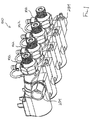
- FIG. 1 is a perspective view of a representative embodiment of an expandable chemical delivery system according to the present invention.
- FIG. 2 is a rear view of the expandable chemical delivery system of FIG. 1 .
- FIG. 3 is a front view of the expandable chemical delivery system of FIG. 1 .
- FIG. 4 is an end view of the expandable chemical delivery system of FIG. 1 .
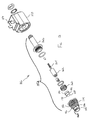
- FIG. 5 is a section view of a representative embodiment of an eductor assembly according to the present invention.
- FIG. 6 is a perspective view of a representative embodiment of a manifold body according to the present invention.
- FIG. 7 is a perspective view of the manifold body of FIG. 6 .
- FIG. 8 is a perspective view of the manifold body of FIG. 6 .
- FIG. 9 is a perspective view of the manifold body of FIG. 6 .
- FIG. 10 is a perspective, partial section view of the manifold body of FIG. 6 .
- FIG. 11 is a perspective view of the manifold body of FIG. 6 prior to attachment to a representative embodiment of a valve assembly according to the present invention.
- FIG. 12 is a perspective view of the coupled manifold body of FIG. 6 with the valve assembly of FIG. 11 .
- FIG. 13 is an exploded perspective view of the valve assembly
- FIG. 14 is a perspective view of a representative embodiment of an eductor member according to the present invention.
- FIG. 15 is a perspective view of the manifold body of FIG. 6 prior to attachment to the eductor member of FIG. 14 .
- FIG. 16 is a perspective view of the coupled manifold body of FIG. 6 with the eductor member of FIG. 14 .
- FIG. 17 is a perspective view of the eductor member of FIG. 14 .
- FIG. 18 is a perspective view of a first and second eductor assembly prior to being approximated to form the expandable chemical delivery system.
- FIG. 19 is a perspective view of the first and second eductor assembly arranged in approximated relation.
- FIG. 20 is a perspective view of four eductor assemblies arranged in approximated relation.
- FIG. 21 is a perspective, partial section view of the expandable chemical delivery system of FIG. 1 taken at line 21 - 21 of FIG. 4 .
- FIG. 22 is a front, perspective view of a representative embodiment of a high-pressure expandable chemical delivery system utilizing a rotary manifold body according to the present invention.
- FIG. 23 is a rear, perspective view of the high-pressure expandable chemical delivery system of FIG. 22 .
- FIG. 24 is a section view of the high pressure expandable chemical delivery system of FIG. 22 .
- FIG. 25 is a front, perspective view of a representative embodiment of a high-pressure expandable chemical delivery system utilizing a linear manifold body according to the present invention.
- FIG. 26 is a front, perspective view of the high-pressure expandable chemical delivery system of FIG. 25 .
- FIG. 27 is an exploded, perspective view of the high-pressure expandable chemical delivery system of FIG. 25 .
- a representative expandable chemical delivery system 100 generally comprises a plurality of eductor assemblies 102 .
- the plurality of eductor assemblies 102 are mechanically and fluidly interconnected such that expandable chemical delivery system 100 is capable of being positioned and mounted as an integral unit.
- expandable chemical delivery system 100 can comprise four eductor assemblies 102 though it will be understood that expandable chemical delivery system 100 generally includes at least two eductor assemblies 102 .
- each eductor assembly 102 generally comprises a manifold body 104 , a valve assembly 106 and an eductor member 108 .
- Manifold body 104 is illustrated generally in FIGS. 6 , 7 , 8 and 9 .
- Manifold body 104 generally comprises a unitary molded body 110 having a substantially flat mounting surface 111 with two or more mounting holes 112 .
- Manifold body 104 is preferably fabricated of a suitable polymeric material that combines the qualities of strength and chemical resistance such as, for example, acetal, nylon, polyphenyl sulfide and the like.
- Manifold body 104 includes a bulk fluid inlet 114 and an axially aligned bulk fluid outlet 116 that are fluidly interconnected with a bulk fluid flow path 118 .
- Bulk fluid inlet 114 and bulk fluid outlet 116 have substantially similar configurations and generally include a mounting face 120 and a sealing groove 122 .
- Manifold body 104 further comprises an eductor port 124 and an axially aligned valve port 126 that are fluidly interconnected by a dispensing fluid flow path 128 .
- Bulk fluid flow path 118 and dispensing fluid flow path 128 are generally arranged transversely to one another and have substantially large enough diameters such that the bulk fluid flow path 118 and dispensing fluid flow path 128 are fluidly interconnected even though their respective flow axis reside on different planes within the manifold body 104 .
- Eductor port 124 generally includes a pair of upper locking apertures 130 and a pair of lower locking apertures 132 .
- a pair of locking grooves 134 reside between corresponding upper locking apertures 130 and lower locking apertures 132 such that a pair of continuous locking bores 135 connect corresponding upper locking apertures 130 and lower locking apertures 132 as shown in FIG. 10 .
- a locking member 136 having a pair of insertion legs 138 is configured such that each leg 138 is simultaneously slidably insertable into corresponding upper locking aperture 130 and lower locking aperture 132 with a portion of legs 138 residing within locking groove 134 .
- Valve port 126 generally includes a valve mounting face 140 and an internal port thread 142 .
- valve assembly 106 typically comprises an actuator portion 150 and a valve portion 152 .
- Valve assembly 106 generally comprises any of a variety of suitable valve constructions including, for example, a cartridge-style valve having a solenoid, armature and a valve seat.
- valve assembly 106 comprises a solenoid valve assembly.
- Actuator portion 150 generally includes an electrical connector 154 and an enclosed electrical coil.
- Valve portion 152 includes a valve seat 156 , a valve plunger 158 , a friction ring 160 , a piston 162 , a spring 164 and a valve stem 166 .
- a valve cap 168 generally comprises a cover member 170 that is positionable over the valve seat 156 to maintain the positioning of the components making up the valve portion 152 as the valve assembly 106 is attached to the manifold body 104 .
- Cover member 170 generally comprises an internal cap thread 172 that is threadably engaged to a valve seat thread 174 as well as an external cap thread 176 that is configured to engage internal port thread 142 on the manifold body 104 .
- Valve plunger 158 includes a projecting portion 178 and an oversized portion 180 defining a sealing flange 182 . Sealing flange 182 is configured to selectively, sealingly engage a dispensing surface 184 within the valve seat 156 .
- Valve seat 156 includes a plurality of valve inlets 186 that allow the bulk fluid from the bulk fluid flow path 118 into the dispensing fluid flow path 128 .
- eductor member 108 generally comprises a molded body 190 having a dispensing inlet 192 , a dispensing outlet 194 and a chemical inlet 196 .
- eductor member 108 can comprise an eductor assembly as disclosed and taught in United States Patent Publication No. 2006/0157131A1, which is hereby incorporated by reference.
- Eductor member 108 is generally sized and selected by a user based upon its capacity to deliver a specified amount of chemical into the bulk fluid for dispensing out the dispensing outlet 194 .
- Dispensing inlet 192 is generally sized for slidable insertion within eductor port 124 and includes a tapered leading edge 198 , a radial sealing groove 200 and a radial locking groove 202 .
- Dispensing outlet 194 generally includes an outlet thread 204 that is configured for connection to a conventional tube fitting for delivering fluid to a point of use. Alternatively, dispensing outlet 194 could further comprise connection orientations such as, for example, a hose barb, a Joint Industry Council (JIC) fitting or a quick-release configuration similar to that employed on dispensing inlet 192 .
- Chemical inlet 196 includes a barbed fitting 206 that is configured for attachment to conventional chemical supply tubing.
- the bulk fluid enters through the dispensing inlet 192 and passes through a spray nozzle 208 entering a mixing zone 210 immediately thereafter. After the bulk fluid exits the spray nozzle 208 , the bulk fluid enters the mixing zone 210 wherein educted chemical and bulk fluid combine and are then conducted out of the eductor member 108 through a divergent zone 212 downstream of the mixing zone 210 .
- Educted chemical is fed to an eductor leg inlet passageway 214 which is comprised of an injection housing 216 , a retention sleeve 218 , a spring 220 , a check ball 222 , and a check valve o-ring 224 .
- bulk fluid typically water
- each eductor assembly 102 is assembled by sealingly attaching the valve assembly 106 and eductor member 108 to the manifold body 104 .
- valve assembly 106 is attached to the valve port 126 by threadably coupling the external cap thread 176 to the internal port thread 142 .
- locking member 136 is slidably inserted into the upper locking apertures 130 such that each insertion leg 138 resides within the corresponding continuous locking bore 135 .
- Dispensing inlet 192 is slidingly inserted into the eductor port 124 such that tapered leading edge 198 advances past the insertion legs 138 residing within locking grooves 134 such that the insertion legs 138 are captured within the radial locking groove 202 .
- An o-ring placed within radial sealing groove 200 seals against an interior perimeter surface of the eductor port 124 .
- the radial sealing mechanism allows the molded body 190 and especially the chemical inlet 196 to be rotatably positioned so as to facilitate easy attachment of the chemical supply tubing to the barbed fitting 206 without interfering with attachment of chemical supply tubing to an adjacent eductor assembly 102 .
- any number of eductor assemblies 102 can be arranged as shown in FIGS. 18 and 19 so as to form expandable chemical delivery system 100 .
- a pair of eductor assemblies 102 are arranged such that the bulk fluid inlet 114 of the first eductor assembly 102 is aligned with the bulk fluid outlet 116 of the second eductor assembly 102 .
- an o-ring is captured within the approximated scaling grooves 122 as the mounting faces 120 come into contact.
- the bulk fluid flow paths 118 of the first and second eductor assemblies 102 are aligned so as to define a common bulk fluid flow path 118 .
- additional eductor assemblies 102 can be arranged and approximated such as, for example, the four eductor assemblies 102 shown in FIG. 20 .
- Coupling assembly 230 generally comprises a coupling tube 232 and a pair of coupling nuts 234 .
- Coupling tube 232 has a diameter smaller than the bulk fluid flow path 118 and includes a first end 236 and a second end 238 .
- a plurality of inlet wall apertures 240 are arranged proximate the first end 236 and a plurality of outlet wall apertures 242 are located proximate the closed end 238 .
- wall apertures can be positioned anywhere along the coupling tube 230 between first end 236 and second end 238 .
- Each end of coupling tube 232 includes an external tube thread 244 and an internal tube thread 245 .
- the coupling tube 232 is inserted through the common bulk fluid flow path 118 defined by the adjacently positioned eductor assemblies 102 such that the external tube thread 244 on the second end 238 extends from the single exposed bulk fluid outlet 116 and the external tube thread 244 on the first end 236 extends from the bulk fluid inlet 114 .
- the coupling nuts 234 are positioned over the first end 236 and second end 238 respectively and tightened over external tube threads 244 .
- the eductor assemblies 102 are forcibly tightened against one another so as to form a sealed and now integral expandable chemical delivery system 100 .
- a bulk fluid supply can be connected at the first end 236 while the internal tube thread 245 at the second end 238 can be used to connect a plumbing connector to an additional chemical delivery system 100 or alternatively, for receiving a conventional threaded plug 248 to close the second end 238 .
- coupling tube 232 is chosen to have a selected tube length 246 corresponding to the number of eductor assemblies 102 .
- the chemical dispensing capacity of expandable chemical delivery system 100 can be selectively increased or decreased by adding/removing eductor assemblies 102 and selecting coupling tube 232 with the corresponding tube length 246 .
- expandable chemical delivery system 100 is assembled based on the number of eductor assemblies 102 necessary to deliver the desired chemicals.
- expandable delivery system 100 can be utilized in an automated car wash using a detergent, a spot-free rinse agent and a liquid wax such that three eductor assemblies 102 are required.
- a control system such as, for example, a microprocessor, Programmable Logic Controller or other known control system actuates the selected valve assembly 106 so as to allow the bulk fluid to flow from bulk fluid inlet 114 , into the coupling tube 232 and out inlet wall apertures 240 and outlet wall apertures 242 such that the bulk fluid enters the bulk fluid flow path 118 .
- valve assemblies 106 can be actuated causing valve plunger 158 to be withdrawn such that sealing flange 182 disengages from the dispensing surface 184 such that the bulk fluid enters the dispensing fluid flow path 128 through the valve inlets 186 .
- valve plunger 158 is withdrawn such that sealing flange 182 disengages from the dispensing surface 184 such that the bulk fluid enters the dispensing fluid flow path 128 through the valve inlets 186 .
- the bulk fluid is directed through the eductor member 108 and out the dispensing outlet 194 with the desired chemical introduced through chemical inlet 196 .
- one or more of the valve assemblies 106 can be simultaneously actuated such that introduction of the bulk fluid through the single bulk fluid inlet 114 allows a plurality of distinct mixed chemical streams to be delivered simultaneously through a plurality of dispensing outlets 194 .
- an alternative embodiment of a high-pressure expandable chemical delivery system 300 performs similarly to expandable chemical delivery system 100 but utilizes a single rotary manifold block 302 with a plurality of valve assemblies 304 , eductor assemblies 306 and a mounting bracket 307 .
- Rotary manifold block 302 includes a single bulk fluid inlet 308 providing bulk fluid to a bulk fluid flow conduit 310 within the rotary manifold block 302 .
- Fluidly interconnected to the bulk fluid flow conduit 310 is a plurality of individual eductor flow conduits 312 that are fluidly connected to an eductor mounting port 314 .
- Each eductor flow conduit 312 is intersected by a valve bore 316 arranged generally transversely to its corresponding eductor flow conduit 312 .
- Each valve bore 316 includes a valve mounting port 318 .
- manifold body 302 can be fabricated to accommodate any number of valve assemblies 304 and eductor assemblies 306 for example, four or six valve and eductor assemblies in a variety of physical arrangements.
- Manifold body 302 can be fabricated of suitable materials including for example, aluminum, stainless steel, titanium and the like and can include resistant coating on wetted parts to improve chemical compatibility and corrosion resistance.
- a high pressure expanable chemical delivery system 400 can comprise a linear manifold block 402 with valve assemblies 106 and eductor members 108 .
- valve assembly 304 can substantially resemble valve assembly 106 such that valve assembly 304 is threadably mountable to the valve mounting port 316 in a manner similar to that of valve assembly 102 and valve port 126 .
- valve assembly 304 can comprise an actuator portion 320 and a valve portion 322 wherein the valve portion 322 includes a valve plunger 324 that is generally configured to slidably engage (closing) or disengage (opening) the eductor flow conduit 310 through the valve bore 314 .
- a user can selectively allow bulk fluid to flow through the educator flow conduit 310 by directing the actuator portion 320 to withdraw the valve plunger 324 from the eductor flow conduit 310 .
- Each eductor assembly 306 can substantially resemble eductor member 108 and can mount to eductor mounting port 312 in a manner similar to eductor member 108 and eductor port 124 .
- Each eductor port 312 includes a pair of locking apertures 330 and corresponding locking groves 332 located within the eductor port 312 to define a pair of continuous locking bores 334 .
- Locking member 136 is again utilized to attach each eductor assembly 306 to its eductor mounting port 312 by simultaneously sliding the insertion legs 138 into the continuous locking bores 334 .
- the eductor assembly 306 can be slidably inserted and captured within the eductor mounting port 312 in a similar manner as previously described with respect to the eductor member 108 and eductor port 124 .
- expandable chemical delivery system 100 and high-pressure expandable chemical delivery system 300 With the current design of expandable chemical delivery system 100 and high-pressure expandable chemical delivery system 300 , no disconnection of bulk fluid supply piping is necessary to accomplish replacement or perform maintenance on individual eductor assemblies or valve assemblies.
- the mounting arrangement of the educator assembly to the manifold body for both expandable chemical delivery system 100 and high-pressure expandable chemical delivery system 300 allow an operator to rotatably manipulate the orientation and position of the eductor assembly, and more specifically, the chemical inlet based upon available space, access and ease of connection to chemical supply piping/tubing.
Abstract
Description
Claims (9)
Priority Applications (2)
| Application Number | Priority Date | Filing Date | Title |
|---|---|---|---|
| US12/246,317 US8322367B2 (en) | 2007-10-05 | 2008-10-06 | Chemical delivery system |
| US13/690,498 US20130160865A1 (en) | 2007-10-05 | 2012-11-30 | Chemical delivery system |
Applications Claiming Priority (2)
| Application Number | Priority Date | Filing Date | Title |
|---|---|---|---|
| US99802107P | 2007-10-05 | 2007-10-05 | |
| US12/246,317 US8322367B2 (en) | 2007-10-05 | 2008-10-06 | Chemical delivery system |
Related Child Applications (1)
| Application Number | Title | Priority Date | Filing Date |
|---|---|---|---|
| US13/690,498 Continuation US20130160865A1 (en) | 2007-10-05 | 2012-11-30 | Chemical delivery system |
Publications (2)
| Publication Number | Publication Date |
|---|---|
| US20090090415A1 US20090090415A1 (en) | 2009-04-09 |
| US8322367B2 true US8322367B2 (en) | 2012-12-04 |
Family
ID=40522256
Family Applications (2)
| Application Number | Title | Priority Date | Filing Date |
|---|---|---|---|
| US12/246,317 Active 2031-05-16 US8322367B2 (en) | 2007-10-05 | 2008-10-06 | Chemical delivery system |
| US13/690,498 Abandoned US20130160865A1 (en) | 2007-10-05 | 2012-11-30 | Chemical delivery system |
Family Applications After (1)
| Application Number | Title | Priority Date | Filing Date |
|---|---|---|---|
| US13/690,498 Abandoned US20130160865A1 (en) | 2007-10-05 | 2012-11-30 | Chemical delivery system |
Country Status (2)
| Country | Link |
|---|---|
| US (2) | US8322367B2 (en) |
| WO (1) | WO2009046433A2 (en) |
Cited By (9)
| Publication number | Priority date | Publication date | Assignee | Title |
|---|---|---|---|---|
| US20150000096A1 (en) * | 2011-12-26 | 2015-01-01 | The Gates Corporation | Extraction device for removing an adapter secured in a port |
| US9339773B2 (en) | 2012-01-31 | 2016-05-17 | Hydra-Flex, Inc. | Chemical dispensing apparatus and related methods |
| US9421559B2 (en) | 2013-02-10 | 2016-08-23 | Hydra-Flex, Inc. | Air driven dispenser for delivery of undiluted chemical |
| US20180065097A1 (en) * | 2015-04-23 | 2018-03-08 | B. Braun Medical Inc. | Compounding device, system, kit, software, and method |
| US10443747B2 (en) | 2016-01-13 | 2019-10-15 | Hydra-Flex Inc. | Manifold with integrated valve |
| US11009143B1 (en) * | 2020-12-22 | 2021-05-18 | Zap Mosquito Solutions Inc. | Expandable solenoid system |
| US11549502B2 (en) * | 2013-07-09 | 2023-01-10 | Deka Products Limited Partnership | Modular valve apparatus and system |
| US11719347B2 (en) * | 2018-05-14 | 2023-08-08 | Cooler Master Co., Ltd. | Control valve |
| US11719350B2 (en) * | 2019-06-12 | 2023-08-08 | Vitesco Technologies USA, LLC | Coolant flow control module |
Families Citing this family (29)
| Publication number | Priority date | Publication date | Assignee | Title |
|---|---|---|---|---|
| US8887743B2 (en) * | 2009-09-10 | 2014-11-18 | Hydra-Flex, Inc. | Chemical delivery system and platform |
| WO2011047088A1 (en) * | 2009-10-13 | 2011-04-21 | Coast Pneumatics, Inc. | Flow controller |
| US9421566B2 (en) * | 2009-12-04 | 2016-08-23 | Hydra-Flex, Inc. | Chemical delivery data acquisition system |
| US8336573B2 (en) * | 2010-03-10 | 2012-12-25 | Coast Pneumatics, Inc. | Modular manifold with quick disconnect valve fittings |
| US8333214B2 (en) * | 2010-03-10 | 2012-12-18 | Coast Pneumatics, Inc. | Modular manifold with quick disconnect valve fittings |
| US8327879B2 (en) * | 2010-03-10 | 2012-12-11 | Coast Pneumatics, Inc. | Modular manifold with quick disconnect valve fittings |
| US8678237B2 (en) | 2011-04-29 | 2014-03-25 | Hydra-Flex, Inc. | Micro dosing panel system |
| US20120279912A1 (en) * | 2011-05-02 | 2012-11-08 | Dubois Chemicals, Inc. | Chemical Mixing System and Method |
| EP2636933B8 (en) * | 2012-03-06 | 2014-08-20 | AFRISO-Euro-Index GmbH | Modular fluid distributor |
| JP6003716B2 (en) * | 2012-04-17 | 2016-10-05 | 株式会社デンソー | Channel switching device |
| US8939322B2 (en) * | 2012-05-07 | 2015-01-27 | Rodney Laible | Wall mounted dispenser |
| ES2443083B1 (en) * | 2012-07-17 | 2014-09-10 | Bnstar Innovations, S. L. | EMPOTRABLE HYDRAULIC CONNECTION ASSEMBLY |
| AU2014302481B2 (en) * | 2013-06-27 | 2017-06-01 | Gates Corporation | Extraction device for removing an adapter secured in a port |
| US10786795B2 (en) * | 2013-11-30 | 2020-09-29 | John Boticki | Individualized flow regulation system and method |
| DE102014216696A1 (en) * | 2014-08-22 | 2016-02-25 | Zf Friedrichshafen Ag | Valve block for a hydraulic or pneumatic system of a gearbox |
| ES2576693B1 (en) | 2015-01-08 | 2017-04-18 | Istobal, S.A. | Distribution panel and modular dosing for car wash centers |
| JP6467711B2 (en) * | 2015-06-24 | 2019-02-13 | Smc株式会社 | Multiple integrated manifold valve |
| DE102016202026A1 (en) * | 2016-02-10 | 2017-08-10 | Mack & Schneider Gmbh | valve means |
| US10731768B2 (en) * | 2016-10-12 | 2020-08-04 | Ecolab Usa Inc. | Systems and methods for manifold valves |
| CN106523743A (en) * | 2016-12-11 | 2017-03-22 | 丹东通博电器(集团)有限公司 | Micro- and small-flow control valve device |
| BE1024953B1 (en) * | 2017-01-31 | 2018-08-30 | Out And Out Chemistry Sprl | Method for connecting at least two fluidic valves and the fluidic communication system implemented |
| US10856668B2 (en) * | 2017-04-10 | 2020-12-08 | Hill-Rom Services, Inc. | Mattress overlay control system with rotary valves and graphical user interface for percussion and vibration, turn assist and microclimate management |
| CN111051752A (en) * | 2017-09-07 | 2020-04-21 | 东京流量仪器仪表株式会社 | Flow control unit |
| ES2959840T3 (en) * | 2018-05-14 | 2024-02-28 | Faster Srl | Support system for quick couplings, in particular for flat-faced cartridge couplings |
| CN110513558A (en) * | 2018-08-21 | 2019-11-29 | 浙江长兴杭华玻璃有限公司 | A kind of air delivering pipeline is died automatic switching control equipment |
| US11808019B2 (en) * | 2019-04-11 | 2023-11-07 | As America, Inc. | Universal rough-in valve and manifold |
| CN210716185U (en) * | 2019-08-28 | 2020-06-09 | 浙江盾安禾田金属有限公司 | Valve body connecting structure and valve assembly with same |
| US20220026004A1 (en) * | 2020-07-22 | 2022-01-27 | Enerco Group, Inc. | Quick connect system and method |
| AU2022256238A1 (en) * | 2021-04-16 | 2023-10-19 | Australian Valve Group Pty Ltd | Modular valve assemblies with optional swing out |
Citations (16)
| Publication number | Priority date | Publication date | Assignee | Title |
|---|---|---|---|---|
| US3788344A (en) | 1971-08-18 | 1974-01-29 | Dyckes Sprinkler Co Ltd | Stacked valve system |
| US4691850A (en) * | 1984-08-09 | 1987-09-08 | Kirschmann John D | Chemical dispensing system |
| US4781467A (en) | 1986-04-09 | 1988-11-01 | Cca, Inc. | Foam-generating apparatus |
| US4848391A (en) | 1988-07-12 | 1989-07-18 | Midtec, Inc. Of America | Expandable manifold for water delivery system |
| US5050631A (en) | 1989-08-23 | 1991-09-24 | Honda Giken Kogyo Kabushiki Kaisha | Fluid diverging system |
| US5435157A (en) * | 1994-01-27 | 1995-07-25 | Sunburst Chemicals, Inc. | Laundry chemical dispenser |
| USD368298S (en) | 1994-05-17 | 1996-03-26 | Midtec, Inc. Of America | Multiple water line valved manifold |
| US5607651A (en) * | 1994-12-06 | 1997-03-04 | Ecolab Inc. | Multiple product dispensing system including dispenser for forming use solution from solid chemical compositions |
| US5927337A (en) * | 1997-03-10 | 1999-07-27 | Lsp Industries, Inc. | Fluid valve and manifold assembly |
| US6240953B1 (en) * | 1998-04-13 | 2001-06-05 | Sunburst Chemicals, Inc. | Multiple cleaning chemical dispenser |
| US6322242B1 (en) | 2000-07-12 | 2001-11-27 | S. C. Johnson Commercial Markets, Inc. | Multistation color coded liquid mixing and dispensing apparatus |
| US6619318B2 (en) * | 2001-09-25 | 2003-09-16 | Hydro Systems Company | Multiple flow rate eductive dispenser |
| JP2004000878A (en) | 2002-04-25 | 2004-01-08 | Yaskawa Electric Corp | Fluid mixing apparatus |
| US6733044B2 (en) * | 2001-08-24 | 2004-05-11 | Yin Hsiang Huang | Device for linking fluid-conditioning units |
| US20060157131A1 (en) * | 2005-01-20 | 2006-07-20 | Harris Jaime L | Eductor assembly with dual-material eductor body |
| US7111644B2 (en) | 2003-04-02 | 2006-09-26 | Sea Tech, Inc. | Manifold |
-
2008
- 2008-10-06 WO PCT/US2008/078967 patent/WO2009046433A2/en active Application Filing
- 2008-10-06 US US12/246,317 patent/US8322367B2/en active Active
-
2012
- 2012-11-30 US US13/690,498 patent/US20130160865A1/en not_active Abandoned
Patent Citations (16)
| Publication number | Priority date | Publication date | Assignee | Title |
|---|---|---|---|---|
| US3788344A (en) | 1971-08-18 | 1974-01-29 | Dyckes Sprinkler Co Ltd | Stacked valve system |
| US4691850A (en) * | 1984-08-09 | 1987-09-08 | Kirschmann John D | Chemical dispensing system |
| US4781467A (en) | 1986-04-09 | 1988-11-01 | Cca, Inc. | Foam-generating apparatus |
| US4848391A (en) | 1988-07-12 | 1989-07-18 | Midtec, Inc. Of America | Expandable manifold for water delivery system |
| US5050631A (en) | 1989-08-23 | 1991-09-24 | Honda Giken Kogyo Kabushiki Kaisha | Fluid diverging system |
| US5435157A (en) * | 1994-01-27 | 1995-07-25 | Sunburst Chemicals, Inc. | Laundry chemical dispenser |
| USD368298S (en) | 1994-05-17 | 1996-03-26 | Midtec, Inc. Of America | Multiple water line valved manifold |
| US5607651A (en) * | 1994-12-06 | 1997-03-04 | Ecolab Inc. | Multiple product dispensing system including dispenser for forming use solution from solid chemical compositions |
| US5927337A (en) * | 1997-03-10 | 1999-07-27 | Lsp Industries, Inc. | Fluid valve and manifold assembly |
| US6240953B1 (en) * | 1998-04-13 | 2001-06-05 | Sunburst Chemicals, Inc. | Multiple cleaning chemical dispenser |
| US6322242B1 (en) | 2000-07-12 | 2001-11-27 | S. C. Johnson Commercial Markets, Inc. | Multistation color coded liquid mixing and dispensing apparatus |
| US6733044B2 (en) * | 2001-08-24 | 2004-05-11 | Yin Hsiang Huang | Device for linking fluid-conditioning units |
| US6619318B2 (en) * | 2001-09-25 | 2003-09-16 | Hydro Systems Company | Multiple flow rate eductive dispenser |
| JP2004000878A (en) | 2002-04-25 | 2004-01-08 | Yaskawa Electric Corp | Fluid mixing apparatus |
| US7111644B2 (en) | 2003-04-02 | 2006-09-26 | Sea Tech, Inc. | Manifold |
| US20060157131A1 (en) * | 2005-01-20 | 2006-07-20 | Harris Jaime L | Eductor assembly with dual-material eductor body |
Non-Patent Citations (2)
| Title |
|---|
| Zurn QickPort� Manifold Brochure, 2007, 2 pages. |
| Zurn QickPort® Manifold Brochure, 2007, 2 pages. |
Cited By (14)
| Publication number | Priority date | Publication date | Assignee | Title |
|---|---|---|---|---|
| US20150000096A1 (en) * | 2011-12-26 | 2015-01-01 | The Gates Corporation | Extraction device for removing an adapter secured in a port |
| US9939090B2 (en) * | 2011-12-26 | 2018-04-10 | Gates Corporation | Extraction device for removing an adapter secured in a port |
| US9339773B2 (en) | 2012-01-31 | 2016-05-17 | Hydra-Flex, Inc. | Chemical dispensing apparatus and related methods |
| US9421559B2 (en) | 2013-02-10 | 2016-08-23 | Hydra-Flex, Inc. | Air driven dispenser for delivery of undiluted chemical |
| US11549502B2 (en) * | 2013-07-09 | 2023-01-10 | Deka Products Limited Partnership | Modular valve apparatus and system |
| US10617863B2 (en) * | 2015-04-23 | 2020-04-14 | B. Braun Medical Inc. | Compounding device, system, kit, software, and method |
| US20180065097A1 (en) * | 2015-04-23 | 2018-03-08 | B. Braun Medical Inc. | Compounding device, system, kit, software, and method |
| US10443747B2 (en) | 2016-01-13 | 2019-10-15 | Hydra-Flex Inc. | Manifold with integrated valve |
| US11092251B2 (en) | 2016-01-13 | 2021-08-17 | Hydra-Flex Inc. | Manifold with integrated valve |
| US20210341067A1 (en) * | 2016-01-13 | 2021-11-04 | Hydra-Flex, Inc. | Manifold with integrated valve |
| US11867301B2 (en) * | 2016-01-13 | 2024-01-09 | Sonny's Hfi Holdings, Llc | Manifold with integrated valve |
| US11719347B2 (en) * | 2018-05-14 | 2023-08-08 | Cooler Master Co., Ltd. | Control valve |
| US11719350B2 (en) * | 2019-06-12 | 2023-08-08 | Vitesco Technologies USA, LLC | Coolant flow control module |
| US11009143B1 (en) * | 2020-12-22 | 2021-05-18 | Zap Mosquito Solutions Inc. | Expandable solenoid system |
Also Published As
| Publication number | Publication date |
|---|---|
| WO2009046433A3 (en) | 2009-06-25 |
| WO2009046433A2 (en) | 2009-04-09 |
| US20130160865A1 (en) | 2013-06-27 |
| US20090090415A1 (en) | 2009-04-09 |
Similar Documents
| Publication | Publication Date | Title |
|---|---|---|
| US8322367B2 (en) | Chemical delivery system | |
| US5772116A (en) | Recirculating paint system having an improved spray gun | |
| US8807158B2 (en) | Eductor assembly with dual-material eductor body | |
| US11867301B2 (en) | Manifold with integrated valve | |
| US5501397A (en) | Recirculating paint system having a valved quick disconnect fluid coupling assembly | |
| US3424439A (en) | Device for mixing and applying foams | |
| US20020003174A1 (en) | Dual material chemical injector for vehicle wash system | |
| US20140042242A1 (en) | Quick-disconnect keyed venturi | |
| US20190105675A1 (en) | Mix on demand sprayer with external by-pass circuit | |
| US6105880A (en) | Mixing block for mixing multi-component reactive material coating systems and an apparatus using same | |
| US6116261A (en) | Solvent and air mixing system with air bleed backflow | |
| US20020157716A1 (en) | Valve system | |
| CN112236609B (en) | Mixing manifold and valve seal assembly | |
| US6233933B1 (en) | Arrangement and method for removal of air from a hydraulic system | |
| WO2021080584A1 (en) | Spool valve for polyurethane foam dispenser | |
| US11110474B2 (en) | Fluid control assembly for mix-on-demand sprayer | |
| CA3092648A1 (en) | Fluid control assembly for mix-on-demand sprayer | |
| WO2021080579A1 (en) | Metal foam dispenser and method of use for polyurethane foam dispensing |
Legal Events
| Date | Code | Title | Description |
|---|---|---|---|
| AS | Assignment |
Owner name: HYDRA-FLEX INC., MINNESOTA Free format text: ASSIGNMENT OF ASSIGNORS INTEREST;ASSIGNORS:HARRIS, JAIME L.;BROWN, GARY A.;KENSINGER, DAVID G.;AND OTHERS;REEL/FRAME:021748/0738;SIGNING DATES FROM 20081010 TO 20081022 Owner name: HYDRA-FLEX INC., MINNESOTA Free format text: ASSIGNMENT OF ASSIGNORS INTEREST;ASSIGNORS:HARRIS, JAIME L.;BROWN, GARY A.;KENSINGER, DAVID G.;AND OTHERS;SIGNING DATES FROM 20081010 TO 20081022;REEL/FRAME:021748/0738 |
|
| STCF | Information on status: patent grant |
Free format text: PATENTED CASE |
|
| REMI | Maintenance fee reminder mailed | ||
| FPAY | Fee payment |
Year of fee payment: 4 |
|
| SULP | Surcharge for late payment | ||
| FEPP | Fee payment procedure |
Free format text: PAYOR NUMBER ASSIGNED (ORIGINAL EVENT CODE: ASPN); ENTITY STATUS OF PATENT OWNER: SMALL ENTITY |
|
| MAFP | Maintenance fee payment |
Free format text: PAYMENT OF MAINTENANCE FEE, 8TH YR, SMALL ENTITY (ORIGINAL EVENT CODE: M2552); ENTITY STATUS OF PATENT OWNER: SMALL ENTITY Year of fee payment: 8 |
|
| AS | Assignment |
Owner name: SONNY'S HFI HOLDINGS, LLC, DELAWARE Free format text: ASSIGNMENT OF ASSIGNORS INTEREST;ASSIGNOR:HYDRA-FLEX, INC.;REEL/FRAME:057056/0062 Effective date: 20210730 |
|
| AS | Assignment |
Owner name: OWL ROCK CAPITAL CORPORATION, NEW YORK Free format text: SECURITY INTEREST;ASSIGNOR:SONNY'S HFI HOLDINGS, LLC;REEL/FRAME:057294/0639 Effective date: 20210825 |
|
| FEPP | Fee payment procedure |
Free format text: ENTITY STATUS SET TO UNDISCOUNTED (ORIGINAL EVENT CODE: BIG.); ENTITY STATUS OF PATENT OWNER: LARGE ENTITY |
|
| MAFP | Maintenance fee payment |
Free format text: PAYMENT OF MAINTENANCE FEE, 12TH YEAR, LARGE ENTITY (ORIGINAL EVENT CODE: M1553); ENTITY STATUS OF PATENT OWNER: LARGE ENTITY Year of fee payment: 12 |