US8322278B2 - Embossing system for embossing pre-formed marker elements - Google Patents
Embossing system for embossing pre-formed marker elements Download PDFInfo
- Publication number
- US8322278B2 US8322278B2 US13/099,988 US201113099988A US8322278B2 US 8322278 B2 US8322278 B2 US 8322278B2 US 201113099988 A US201113099988 A US 201113099988A US 8322278 B2 US8322278 B2 US 8322278B2
- Authority
- US
- United States
- Prior art keywords
- carrier
- elements
- embossing
- marker
- marker elements
- Prior art date
- Legal status (The legal status is an assumption and is not a legal conclusion. Google has not performed a legal analysis and makes no representation as to the accuracy of the status listed.)
- Active
Links
Images


Classifications
-
- G—PHYSICS
- G09—EDUCATION; CRYPTOGRAPHY; DISPLAY; ADVERTISING; SEALS
- G09F—DISPLAYING; ADVERTISING; SIGNS; LABELS OR NAME-PLATES; SEALS
- G09F3/00—Labels, tag tickets, or similar identification or indication means; Seals; Postage or like stamps
- G09F3/02—Forms or constructions
- G09F3/0295—Labels or tickets for tubes, pipes and the like
-
- B—PERFORMING OPERATIONS; TRANSPORTING
- B44—DECORATIVE ARTS
- B44B—MACHINES, APPARATUS OR TOOLS FOR ARTISTIC WORK, e.g. FOR SCULPTURING, GUILLOCHING, CARVING, BRANDING, INLAYING
- B44B5/00—Machines or apparatus for embossing decorations or marks, e.g. embossing coins
- B44B5/02—Dies; Accessories
-
- B—PERFORMING OPERATIONS; TRANSPORTING
- B65—CONVEYING; PACKING; STORING; HANDLING THIN OR FILAMENTARY MATERIAL
- B65C—LABELLING OR TAGGING MACHINES, APPARATUS, OR PROCESSES
- B65C9/00—Details of labelling machines or apparatus
- B65C9/08—Label feeding
- B65C9/10—Label magazines
-
- B—PERFORMING OPERATIONS; TRANSPORTING
- B65—CONVEYING; PACKING; STORING; HANDLING THIN OR FILAMENTARY MATERIAL
- B65C—LABELLING OR TAGGING MACHINES, APPARATUS, OR PROCESSES
- B65C9/00—Details of labelling machines or apparatus
- B65C9/08—Label feeding
- B65C9/12—Removing separate labels from stacks
-
- B—PERFORMING OPERATIONS; TRANSPORTING
- B65—CONVEYING; PACKING; STORING; HANDLING THIN OR FILAMENTARY MATERIAL
- B65H—HANDLING THIN OR FILAMENTARY MATERIAL, e.g. SHEETS, WEBS, CABLES
- B65H5/00—Feeding articles separated from piles; Feeding articles to machines
-
- G—PHYSICS
- G09—EDUCATION; CRYPTOGRAPHY; DISPLAY; ADVERTISING; SEALS
- G09F—DISPLAYING; ADVERTISING; SIGNS; LABELS OR NAME-PLATES; SEALS
- G09F3/00—Labels, tag tickets, or similar identification or indication means; Seals; Postage or like stamps
- G09F3/08—Fastening or securing by means not forming part of the material of the label itself
- G09F3/18—Casings, frames or enclosures for labels
- G09F3/20—Casings, frames or enclosures for labels for adjustable, removable, or interchangeable labels
- G09F3/205—Casings, frames or enclosures for labels for adjustable, removable, or interchangeable labels specially adapted for electric cables, pipes or the like
Definitions
- FIGS. 5 to 8 An alternative embodiment of carrier device 101 is shown in FIGS. 5 to 8 .
- the device 101 is generally similar to the device of FIGS. 1 to 4 , however in this instance the spines 113 of the carrier elements are mounted pivotally in a housing case 151 within which the carrier elements 103 are received in the compact configuration as shown in FIG. 5 .
- the carrier elements 103 are configured generally as the carrier elements 3 of the previous embodiment except in relation to the free end detail.
- the free end of the carrier elements is provided with a resilient detent 154 to cooperate with a detent shoulder (not shown) on the inside of the distal end wall 155 of the housing case 151 .
- the carrier device 1 provides a convenient means of carrying and selecting the markers when in use.
Abstract
A marker carrier device has carrier elements for carrying respective markers, the device being re-configurable between a compact configuration and a selection configuration in which the markers are accessibly presented for selection. Carrier devices loaded with markers are received at a receiving station of a marking unit. The markers are selected from the carrier individually while in the marking unit and marked by a marking device with a predetermined indicium.
Description
This is a divisional application based on U.S. National Phase application Ser. No. 11/913,040, filed Mar. 19, 2008, which is a National Phase of PCT/GB2006/001572 (WO 2006/117528 A2), filed Apr. 28, 2006, which claims priority to United Kingdom Application No. 0508728.3, filed Apr. 29, 2005 and United Kingdom Application No. 0520474.8, filed Oct. 10, 2005.
The present invention relates to a marker system and a carrier device for carrying individual pre-formed markers.
Elongate marker strips of plastics, metal or other materials are known for the purpose of identifying, for example electric cables. The markers are typically printed or embossed with an identifier indicia and attached to the cable, in order to identify the relevant cable.
An improved marker system and carrier device for such markers have been devised.
According to a first aspect, the present invention provides a carrier device for marker elements, the carrier device comprising a plurality of carrier elements for carrying respective marker elements, the device being re-configurable between a compact configuration and a selection configuration in which the markers are accessibly presented for selection.
It is preferred that the marker elements are presented in a fanned out configuration in the selection configuration, and in a non fanned out configuration in the compact configuration. Beneficially, the marker elements are presented in a radially spaced array in the selection configuration. The carrier elements preferably interlock one another in the compact configuration.
The carrier elements are preferably rotatable relative to one another to move between the compact configuration and the selection configuration.
Desirably, the carrier elements are arranged in a stack or row when in the compact configuration.
It is preferred that the system includes detent means for retaining the carrier elements interlocked in the compact configuration. Advantageously, the carrier elements are provided with complementary engaging formations comprising the detent means. It is desirable that the detent means is capable of being overcome by hand force in order to move the carrier elements from the compact position.
The carrier elements preferably include grip means for retaining the respective marker elements. The grip means may comprise one or more resilient clamp elements provided for a respective carrier element. The clamp element is preferably biased to a normally clamped position.
Typically, the carrier elements and the marker elements are elongate and the carrier elements are configured to facilitate insertion and removal of the marker elements in a transfer direction which is transverse to the longitudinal direction. Preferably the carrier elements are rotatable about a common pivot spine. Beneficially the common pivot spine is positioned proximate one end of the respective carrier elements.
It is a preferred feature of the arrangement that the marker elements can be removed from the respective carrier elements in both the compact and the selection configuration. This aids in automatic handling such as for example enabling the marker elements to be picked from the device when in the compact configuration, loaded in a printing or embossing device.
The carrier elements are configured, beneficially, to receive a single marker element. Desirably, the marker elements are substantially laid flat received on a support of the respective carrier element.
According to an alternative aspect, the present invention provides a marker system for marking preformed markers the marker system including:
-
- a marker carrier device for carrying a plurality of markers received in respective carrier elements comprising the marker carrier device;
- a marking unit including:
- a receiving station for receiving the marker carrier device;
- a marking device; and,
- means for selecting individual marker elements in the carrier device and operating the marking device to mark the respective marker element with a predetermined indicium.
It is preferred that the marking unit includes a picker arrangement to remove the marker elements from the carrier device and present the respective marker elements to the marking device.
Beneficially, the respective marker elements are returned to the carrier device following marking.
Desirably, the system is programmable to predetermine the indicium applied to a respective marker. Beneficially the system therefore includes user input means (such as a keypad or the like) to determine the indicium applied to the marker element.
The marking device preferably comprises an embossing device arranged to impart an embossed indicium to the marker element.
The carrier device preferably comprises a plurality of movable carrier elements re-configurable between a compact configuration and a selection configuration in which the markers are accessibly presented for selection, the carrier elements being moved to the selection configuration to enable the marker elements to be selected for marking in the marking unit.
In one embodiment the carrier device and marking device are sequentially relatively indexed to enable marker elements to be selected for marking. In alternative embodiment the marker carrier device could be indexed. The marked marker elements are preferably returned to the carrier elements from whence they came for dispatch from the unit.
The marker carrier used in the system has preferred and advantageous features in accordance with the marker carrier device according to the first aspect of the invention.
The invention will now be further described, by way of example only, and with reference to the accompanying drawings, in which:
Referring to the drawings, and initially to FIGS. 1 and 2 , there is shown a carrier device 1 for individual selected flat markers 2. The carrier device includes a series of elongate carrier elements 3, each shaped and configured to hold a single respective marker 2. The carrier elements 3 are of plastics material and joined at a common pivotal spine 4 such that each respective carrier element is pivotal relative to others in the device 1. The pivotal spine is formed by boss formations 6 (formed integrally at the ends of respective carrier elements 3), and arranged to rotatably engage with a socket formation 7 provided on the reverse sides of the carrier elements (these are shown most clearly in FIGS. 3 and 4 ). A resilient plastics clip 23 is used to hold the spine together.
The distal end of the respective carrier elements 3 are provided with detent formations 9, 10 which cooperate with a recess 12 (FIG. 3 ) formed on the reverse side side of the carrier elements. In this way the adjacent carrier elements 2 can interlock and the carrier device 1 can be held in a compact or closed interlocked configuration in which the carriers are ‘in-line’ in a row or stack (bottom seven carrier elements in FIG. 1 ) or ‘fanned out’ in a pivotally radially spaced ‘selection’ configuration, in which the markers 2 can be easily seen and selected (upper three carrier elements in FIG. 1 ). The detent formations are shaped and dimensioned with respect to the recess 12 such that the carrier elements can be held ‘in line’ in the compact configuration, but displaced to the fanned out selection configuration by the user by hand.
The body of the carrier element comprises a longitudinal spine 13 and supports 14, 19, 20 against which the marker element is clamped by means of longitudinally spaced clamps 15, 16. The clamps 15,16 included spaced resilient arms 22 which are shaped and configured to be normally biased to a position of clamping engagement. As the marker element 2 slides into and out of the clamps 15, 16 the arms 22 resiliently flex. The majority of the upper surface of the markers 2 when clamped to a respective carrier element are visible, which makes correct marker element identification and selection easier.
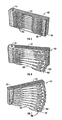
An alternative embodiment of carrier device 101 is shown in FIGS. 5 to 8 . The device 101 is generally similar to the device of FIGS. 1 to 4 , however in this instance the spines 113 of the carrier elements are mounted pivotally in a housing case 151 within which the carrier elements 103 are received in the compact configuration as shown in FIG. 5 . The carrier elements 103 are configured generally as the carrier elements 3 of the previous embodiment except in relation to the free end detail. As shown in FIG. 8 , the free end of the carrier elements is provided with a resilient detent 154 to cooperate with a detent shoulder (not shown) on the inside of the distal end wall 155 of the housing case 151. This ensures the carrier elements 103 are generally securely retained within the housing case 151 but permits manual force to move the carrier element pivotally from the housing case 151. The projection 157 carrying the detent 154 enables the user to grip the carrier element for movement, and also provides a resilient connection at bridge portion 158. Projecting upwardly from the distal end of the carrier element 103 is a lug 109 which is arrayed to be received in a slot 110 (shown in dashed line in FIG. 8 ) which is provided on the underside of the immediately upwardly adjacent carrier element 103 in the stack. In this way, pulling out the lowermost carrier element 103 causes the entire stack of carrier elements 103 to fan out (as shown progressively in FIGS. 6 and 7 ) as the lugs 109 move in slots 110 and then cause the adjacent carrier to pivotally move (fanning out) when the lug 109 abuts the end of the slot of the respective upwardly adjacent carrier elements 103. In the selection configuration shown in FIG. 7 , the carrier elements are fully fanned giving clear view of the markers 108 in the carrier device.
Typically the marker elements are loaded (either manually or mechanically) into the carrier elements 2 of a carrier device 1 in an unmarked state. The unmarked, marker loaded, device is transported to a use location together with a portable marker unit 25 as shown in FIGS. 5A and 5B . The portable marker unit 25 comprises a programmable input device 26 (such as an alpha numeric key pad) and a processor 27. The processor 27 controls a picker device 28 and embossing device 29. The carrier device 1 is loaded into the unit at a docking station 30. The picker device 28 and embossing device 29 are arranged to be indexed upwardly or downwardly to adjacent successive carrier elements 2, and operate to slide out the marker elements 2 from the carrier elements 3 in a direction away from the spine 13. the picker device 28 then transfers the marker element 2 to the embossing device where the appropriate indicia is embossed onto the marker element 2. Subsequently, the marker element is returned by the picker device 28 to the respective carrier element from which it was originally selected.
In a modified embodiment a magazine containing a number of carrier devices 1 (for example ten) can be loaded into a loading station for the unit. A single carrier device 1 is then fed to the docking station 30 for embossing of the blank marker elements 2. In this way the unit can be used for relatively high embossing runs. In addition a separate dispatch station may be provided for the unit. Following embossing of all required marker elements in a relevant carrier 1, the carrier may pass to the dispatch station whilst a further carrier 1 to be concurrently loaded for embossing. The unit may therefore, store and process carriers effectively continuously.
It is possible that alternatively to the picker device 28 and embossing device 29 being moved in indexed fashion, the carrier device 1 could be moved in an indexed manner. The carrier elements 2 of the carrier device 1, when positioned in the docking station 30, could be displaced pivotally to enable easier access for embossing and/or picking. It is also possible for other configurations of carrier device to be used. For example a disc carrier with the marker elements aligned radially could be used. In such an embodiment the disc carrier could be mounted for rotary indexing in the docking station and the marker elements moved radially into and out of the carrier.
Because the system is portable and programmable, markers can be marked up on site with appropriate indicia. The carrier device 1 provides a convenient means of carrying and selecting the markers when in use.
When each marker in a carrier device 201 has been picked, embossed and returned to the respective carrier device, the carrier device is driven upwardly from the picking station 229 lower rack 238 and loaded onto the upper rack 237, for subsequent onward shipment.
Claims (5)
1. An embossing system for embossing preformed marker elements for the identification of cables, the embossing system including:
a portable marker element carrier device configured to be carried and comprising a plurality of elongate carrier elements arranged in a stacked configuration and configured to receive a plurality of respective marker elements;
a marking unit including:
a docking station for detachably receiving the marker element carrier device;
an embossing device arranged to impart an embossed indicia to the marker elements; and,
means for selecting individual marker elements in the carrier device and operating the embossing device to mark the respective marker element with a predetermined indicia;
a picker arrangement arranged to be indexed upwardly and downwardly relative to said stacked carrier elements and to slidingly remove the marker elements from the carrier device and present the respective marker elements to the embossing device and to return the respective marker elements to the carrier device following embossing; and
wherein the portable carrier device is reconfigurable between said stacked configuration in which the marker elements are accessibly presented for selection by the picker arrangement, and when detached from the marking unit, a fanned out configuration in which the marker elements can be easily seen and selected by a user.
2. The embossing system according to claim 1 , wherein the means for selecting individual marker elements in the carrier device and operating the embossing device is programmable to predetermine the indicia applied to a respective marker element.
3. The embossing system according to claim 1 , wherein the carrier device comprises a plurality of movable carrier elements re-configurable between a compact configuration and a selection configuration in which the marker elements are accessibly presented for selection, the carrier elements being moved to the selection configuration to enable the marker elements to be selected for marking in the marking unit.
4. The embossing system according to claim 1 , wherein the carrier device and embossing device are sequentially relatively indexed to enable marker elements to be selected for marking.
5. The embossing system according to claim 1 , wherein the picker arrangement is indexed to pick marker elements sequentially from the carrier device and deliver the marker elements to the embossing device.
Priority Applications (1)
| Application Number | Priority Date | Filing Date | Title |
|---|---|---|---|
| US13/099,988 US8322278B2 (en) | 2005-04-29 | 2011-05-03 | Embossing system for embossing pre-formed marker elements |
Applications Claiming Priority (7)
| Application Number | Priority Date | Filing Date | Title |
|---|---|---|---|
| GBGB0508728.3A GB0508728D0 (en) | 2005-04-29 | 2005-04-29 | Marker system and carrier device |
| GB0508728.3 | 2005-04-29 | ||
| GB0520474.8 | 2005-10-10 | ||
| GB0520474A GB2425646B (en) | 2005-04-29 | 2005-10-10 | Marker system and carrier device |
| PCT/GB2006/001572 WO2006117528A2 (en) | 2005-04-29 | 2006-04-28 | Marker system and carrier device |
| US91304008A | 2008-03-19 | 2008-03-19 | |
| US13/099,988 US8322278B2 (en) | 2005-04-29 | 2011-05-03 | Embossing system for embossing pre-formed marker elements |
Related Parent Applications (3)
| Application Number | Title | Priority Date | Filing Date |
|---|---|---|---|
| PCT/GB2006/001572 Division WO2006117528A2 (en) | 2005-04-29 | 2006-04-28 | Marker system and carrier device |
| US11/913,040 Division US8316765B2 (en) | 2005-04-29 | 2006-04-28 | Carrier device for carrying marker elements |
| US91304008A Division | 2005-04-29 | 2008-03-19 |
Publications (2)
| Publication Number | Publication Date |
|---|---|
| US20110206442A1 US20110206442A1 (en) | 2011-08-25 |
| US8322278B2 true US8322278B2 (en) | 2012-12-04 |
Family
ID=34674058
Family Applications (2)
| Application Number | Title | Priority Date | Filing Date |
|---|---|---|---|
| US11/913,040 Active 2029-01-09 US8316765B2 (en) | 2005-04-29 | 2006-04-28 | Carrier device for carrying marker elements |
| US13/099,988 Active US8322278B2 (en) | 2005-04-29 | 2011-05-03 | Embossing system for embossing pre-formed marker elements |
Family Applications Before (1)
| Application Number | Title | Priority Date | Filing Date |
|---|---|---|---|
| US11/913,040 Active 2029-01-09 US8316765B2 (en) | 2005-04-29 | 2006-04-28 | Carrier device for carrying marker elements |
Country Status (4)
| Country | Link |
|---|---|
| US (2) | US8316765B2 (en) |
| EP (1) | EP2287014B1 (en) |
| JP (1) | JP4994363B2 (en) |
| GB (2) | GB0508728D0 (en) |
Cited By (1)
| Publication number | Priority date | Publication date | Assignee | Title |
|---|---|---|---|---|
| US20140338241A1 (en) * | 2011-09-16 | 2014-11-20 | Murrplastik Systemtechnik Gmbh | Arrangement of identification plates |
Families Citing this family (11)
| Publication number | Priority date | Publication date | Assignee | Title |
|---|---|---|---|---|
| GB0508728D0 (en) | 2005-04-29 | 2005-06-08 | Spirent Plc | Marker system and carrier device |
| US9481200B2 (en) * | 2010-03-03 | 2016-11-01 | Panduit Corp. | Embossing system |
| GB2492530A (en) | 2011-06-17 | 2013-01-09 | Hellermann Tyton Ltd | Supply assembly for a marker system |
| KR101873915B1 (en) * | 2014-12-18 | 2018-07-06 | 코닝 리서치 앤드 디벨롭먼트 코포레이션 | Article and method for parallel labeling of an array of connections |
| USD787956S1 (en) * | 2015-05-20 | 2017-05-30 | Dart Industries Inc. | Measuring cup |
| RU2622825C1 (en) * | 2015-05-20 | 2017-06-20 | Дарт Индастриз Инк. | Measuring tanks put one into another |
| US10903632B2 (en) | 2016-02-05 | 2021-01-26 | Hellermanntyton Corporation | Adjustable P-clamp with multiple mounting options |
| US10899152B2 (en) | 2016-06-23 | 2021-01-26 | Cabin Creek, Llc | Systems and methods for providing an ink pad |
| USD908429S1 (en) * | 2019-10-24 | 2021-01-26 | Toshikazu Tsukii | Double turning trays with rotatable propeller |
| CN114211866A (en) * | 2021-12-29 | 2022-03-22 | 绍兴寿春针纺织有限公司 | Folding hanging is PUA hot melt adhesive gilding press for fan |
| US20240051114A1 (en) * | 2022-08-11 | 2024-02-15 | Bryan Hickey | Toolset organizer |
Citations (21)
| Publication number | Priority date | Publication date | Assignee | Title |
|---|---|---|---|---|
| US183232A (en) | 1876-10-10 | Improvement in paper boxes | ||
| GB850670A (en) | 1958-04-02 | 1960-10-05 | British Insulated Callenders | Improvements relating to indenting tools |
| US3188157A (en) | 1962-11-05 | 1965-06-08 | Spatz Corp | Stacked dispensing containers |
| FR2114969A5 (en) | 1971-11-30 | 1972-06-30 | Zippertubing Co | |
| USD267153S (en) | 1980-10-28 | 1982-12-07 | Ketcham & Mcdougall | Desk receptacle for writing instruments and office supplies or the like |
| GB2137586A (en) | 1983-03-29 | 1984-10-10 | Sjomark Sven Ake Roland | A combined magazine and fitting device for labelling sleeves |
| US4560078A (en) | 1984-09-21 | 1985-12-24 | Dubuisson Joseph E | Case with rotary telescopic sections |
| US4648184A (en) * | 1984-02-17 | 1987-03-10 | F. Wieland Elektrische Industrie Gmbh | Keyboard controlled apparatus for the identification of small parts |
| US4655129A (en) | 1985-10-11 | 1987-04-07 | W. H. Brady Co. | Marker sleeve processing machine |
| US4761086A (en) * | 1986-05-23 | 1988-08-02 | Thomas & Betts Corporation | Support device for wire marker sleeves |
| US4807773A (en) | 1987-09-21 | 1989-02-28 | Aaron Tsai | Vertically assembled compact |
| US4815483A (en) | 1987-04-20 | 1989-03-28 | Dugrenier Robert | Cosmetic package with stacked rotatable trays |
| US5423434A (en) | 1994-06-09 | 1995-06-13 | Chen; Franks | Adjustable disk show rack |
| US5862751A (en) * | 1995-09-01 | 1999-01-26 | Thomas & Betts Corporation | Apparatus, methods, and systems for wire marking |
| US6341932B1 (en) * | 1999-06-14 | 2002-01-29 | Dainippon Screen Mfg. Co., Ltd. | Plate feeding apparatus and method |
| WO2002063594A2 (en) | 2001-02-05 | 2002-08-15 | Mary Deans | Foldable photo display unit |
| WO2002095890A2 (en) | 2001-05-23 | 2002-11-28 | Sibocar S.R.L. | Means and method of applying identification marks for cables and electric components |
| JP2003107998A (en) | 2001-06-25 | 2003-04-11 | Matsuhashi Seisakusho:Kk | Displayed matter holding device |
| US6796241B2 (en) * | 2002-05-31 | 2004-09-28 | José Luis Catalán | Method and apparatus for producing images on eggs |
| GB2425646A (en) | 2005-04-29 | 2006-11-01 | Spirent Plc | Marker system and carrier device |
| USD534318S1 (en) | 2005-09-30 | 2006-12-26 | Vincent Ditrichstein | Cosmetic palette |
Family Cites Families (3)
| Publication number | Priority date | Publication date | Assignee | Title |
|---|---|---|---|---|
| DE1022655B (en) * | 1953-06-10 | 1958-01-16 | Paul Hellermann | Arrangement of identification rings for electrical lines |
| JPH1035172A (en) * | 1996-07-17 | 1998-02-10 | Toshiko Fujisaki | Stand holder |
| WO2004052065A1 (en) * | 2002-11-29 | 2004-06-17 | Fujitsu Limited | Electronic device |
-
2005
- 2005-04-29 GB GBGB0508728.3A patent/GB0508728D0/en not_active Ceased
- 2005-10-10 GB GB0520474A patent/GB2425646B/en active Active
-
2006
- 2006-04-28 EP EP10192191.4A patent/EP2287014B1/en active Active
- 2006-04-28 US US11/913,040 patent/US8316765B2/en active Active
- 2006-04-28 JP JP2008508304A patent/JP4994363B2/en not_active Expired - Fee Related
-
2011
- 2011-05-03 US US13/099,988 patent/US8322278B2/en active Active
Patent Citations (21)
| Publication number | Priority date | Publication date | Assignee | Title |
|---|---|---|---|---|
| US183232A (en) | 1876-10-10 | Improvement in paper boxes | ||
| GB850670A (en) | 1958-04-02 | 1960-10-05 | British Insulated Callenders | Improvements relating to indenting tools |
| US3188157A (en) | 1962-11-05 | 1965-06-08 | Spatz Corp | Stacked dispensing containers |
| FR2114969A5 (en) | 1971-11-30 | 1972-06-30 | Zippertubing Co | |
| USD267153S (en) | 1980-10-28 | 1982-12-07 | Ketcham & Mcdougall | Desk receptacle for writing instruments and office supplies or the like |
| GB2137586A (en) | 1983-03-29 | 1984-10-10 | Sjomark Sven Ake Roland | A combined magazine and fitting device for labelling sleeves |
| US4648184A (en) * | 1984-02-17 | 1987-03-10 | F. Wieland Elektrische Industrie Gmbh | Keyboard controlled apparatus for the identification of small parts |
| US4560078A (en) | 1984-09-21 | 1985-12-24 | Dubuisson Joseph E | Case with rotary telescopic sections |
| US4655129A (en) | 1985-10-11 | 1987-04-07 | W. H. Brady Co. | Marker sleeve processing machine |
| US4761086A (en) * | 1986-05-23 | 1988-08-02 | Thomas & Betts Corporation | Support device for wire marker sleeves |
| US4815483A (en) | 1987-04-20 | 1989-03-28 | Dugrenier Robert | Cosmetic package with stacked rotatable trays |
| US4807773A (en) | 1987-09-21 | 1989-02-28 | Aaron Tsai | Vertically assembled compact |
| US5423434A (en) | 1994-06-09 | 1995-06-13 | Chen; Franks | Adjustable disk show rack |
| US5862751A (en) * | 1995-09-01 | 1999-01-26 | Thomas & Betts Corporation | Apparatus, methods, and systems for wire marking |
| US6341932B1 (en) * | 1999-06-14 | 2002-01-29 | Dainippon Screen Mfg. Co., Ltd. | Plate feeding apparatus and method |
| WO2002063594A2 (en) | 2001-02-05 | 2002-08-15 | Mary Deans | Foldable photo display unit |
| WO2002095890A2 (en) | 2001-05-23 | 2002-11-28 | Sibocar S.R.L. | Means and method of applying identification marks for cables and electric components |
| JP2003107998A (en) | 2001-06-25 | 2003-04-11 | Matsuhashi Seisakusho:Kk | Displayed matter holding device |
| US6796241B2 (en) * | 2002-05-31 | 2004-09-28 | José Luis Catalán | Method and apparatus for producing images on eggs |
| GB2425646A (en) | 2005-04-29 | 2006-11-01 | Spirent Plc | Marker system and carrier device |
| USD534318S1 (en) | 2005-09-30 | 2006-12-26 | Vincent Ditrichstein | Cosmetic palette |
Non-Patent Citations (5)
| Title |
|---|
| European Patent Office, "PCT Written Opinion of the International Searching Authority," Jan. 11, 2006 and Jan. 31, 2006, pp. 1-12. |
| http://www.canford.co.uk/commerce/resources/catdetails/2350.pdf, "A holder for reels of cable marking plastic.". |
| http://www.partex.co.uk/cas.html, "A hinged cassette dispenser for cable markers.". |
| http:/www.partex.co.uk/markties.html#ident, "A solid identity tag which can be used as a marker for cables.". |
| International Search Report, 2 Apr. 2007, p. 1-5. |
Cited By (2)
| Publication number | Priority date | Publication date | Assignee | Title |
|---|---|---|---|---|
| US20140338241A1 (en) * | 2011-09-16 | 2014-11-20 | Murrplastik Systemtechnik Gmbh | Arrangement of identification plates |
| US9053644B2 (en) * | 2011-09-16 | 2015-06-09 | Murrplastik Systemtechnik Gmbh | Arrangement of identification plates |
Also Published As
| Publication number | Publication date |
|---|---|
| EP2287014B1 (en) | 2016-11-30 |
| JP4994363B2 (en) | 2012-08-08 |
| GB2425646B (en) | 2010-10-27 |
| US8316765B2 (en) | 2012-11-27 |
| GB0520474D0 (en) | 2005-11-16 |
| EP2287014A1 (en) | 2011-02-23 |
| GB0508728D0 (en) | 2005-06-08 |
| GB2425646A (en) | 2006-11-01 |
| US20080267686A1 (en) | 2008-10-30 |
| US20110206442A1 (en) | 2011-08-25 |
| JP2009504111A (en) | 2009-01-29 |
Similar Documents
| Publication | Publication Date | Title |
|---|---|---|
| US8322278B2 (en) | Embossing system for embossing pre-formed marker elements | |
| JP4237621B2 (en) | Methods, systems, and arrangements for handling electronic component tapes | |
| US7952798B2 (en) | Holding device for microscope slides with tissue specimens | |
| US20030051821A1 (en) | System for handling components at a component mounting machine | |
| US20040149383A1 (en) | Method for transferring component tape information to a component mounting machine and means therefore | |
| US9975237B2 (en) | Platform with removable pegs for organizing sockets | |
| JP2005500523A5 (en) | ||
| US20050276729A1 (en) | Sample collection container rack overlays | |
| EP0322507B1 (en) | A holder for paper-keeping bags | |
| CN108587854B (en) | Sample slide storage tray, tray storage cabinet and slide identification device | |
| EP1874560B1 (en) | Marker system and carrier device | |
| EP0253790B1 (en) | A method and arrangement for transferring articles | |
| GB2470507A (en) | Marker System | |
| US20040020032A1 (en) | Spring-wire clip applicator and method, and spring wire clips useful therewith | |
| US2765925A (en) | Sorting aid | |
| DK2314414T3 (en) | A magazine for temporary storage of workpieces | |
| CN217675367U (en) | Feeding device and electrode bar sorting machine | |
| EP2720953B1 (en) | A supply assembly for a marker system | |
| EP1535248B1 (en) | Arrangement for handling banknotes and/or other documents | |
| CN117616890A (en) | System and method for material storage and pick-up | |
| US4052049A (en) | Card injecting apparatus | |
| JPS6228179A (en) | Thumb tack treater | |
| US20040088831A1 (en) | Holder for securing objects | |
| DE60101421D1 (en) | Automatic machine for regrouping sample sheets | |
| JPH0632199B2 (en) | 3,5-inch floppy disk sorting device |
Legal Events
| Date | Code | Title | Description |
|---|---|---|---|
| STCF | Information on status: patent grant |
Free format text: PATENTED CASE |
|
| FPAY | Fee payment |
Year of fee payment: 4 |
|
| MAFP | Maintenance fee payment |
Free format text: PAYMENT OF MAINTENANCE FEE, 8TH YEAR, LARGE ENTITY (ORIGINAL EVENT CODE: M1552); ENTITY STATUS OF PATENT OWNER: LARGE ENTITY Year of fee payment: 8 |