US8322102B2 - Wall panel system - Google Patents
Wall panel system Download PDFInfo
- Publication number
- US8322102B2 US8322102B2 US13/417,945 US201213417945A US8322102B2 US 8322102 B2 US8322102 B2 US 8322102B2 US 201213417945 A US201213417945 A US 201213417945A US 8322102 B2 US8322102 B2 US 8322102B2
- Authority
- US
- United States
- Prior art keywords
- wall
- groove
- panel frame
- panel
- rail
- Prior art date
- Legal status (The legal status is an assumption and is not a legal conclusion. Google has not performed a legal analysis and makes no representation as to the accuracy of the status listed.)
- Active
Links
- 238000000465 moulding Methods 0.000 claims description 2
- 239000000463 material Substances 0.000 description 8
- 239000002023 wood Substances 0.000 description 4
- 230000008901 benefit Effects 0.000 description 3
- 229920003023 plastic Polymers 0.000 description 3
- 239000004033 plastic Substances 0.000 description 3
- 239000004800 polyvinyl chloride Substances 0.000 description 3
- 229910052782 aluminium Inorganic materials 0.000 description 2
- XAGFODPZIPBFFR-UHFFFAOYSA-N aluminium Chemical compound [Al] XAGFODPZIPBFFR-UHFFFAOYSA-N 0.000 description 2
- 238000012986 modification Methods 0.000 description 2
- 230000004048 modification Effects 0.000 description 2
- 239000002245 particle Substances 0.000 description 2
- 229920002430 Fibre-reinforced plastic Polymers 0.000 description 1
- 229910019142 PO4 Inorganic materials 0.000 description 1
- 229920002522 Wood fibre Polymers 0.000 description 1
- 239000004568 cement Substances 0.000 description 1
- 239000003086 colorant Substances 0.000 description 1
- 239000002131 composite material Substances 0.000 description 1
- 238000010276 construction Methods 0.000 description 1
- 239000004035 construction material Substances 0.000 description 1
- 230000008602 contraction Effects 0.000 description 1
- 230000000694 effects Effects 0.000 description 1
- 230000007613 environmental effect Effects 0.000 description 1
- 239000011151 fibre-reinforced plastic Substances 0.000 description 1
- 238000003780 insertion Methods 0.000 description 1
- 230000037431 insertion Effects 0.000 description 1
- 229910052751 metal Inorganic materials 0.000 description 1
- 239000002184 metal Substances 0.000 description 1
- 238000000034 method Methods 0.000 description 1
- NBIIXXVUZAFLBC-UHFFFAOYSA-K phosphate Chemical compound [O-]P([O-])([O-])=O NBIIXXVUZAFLBC-UHFFFAOYSA-K 0.000 description 1
- 239000010452 phosphate Substances 0.000 description 1
- 239000007787 solid Substances 0.000 description 1
- 230000007704 transition Effects 0.000 description 1
- 239000002025 wood fiber Substances 0.000 description 1
Images


Classifications
-
- E—FIXED CONSTRUCTIONS
- E04—BUILDING
- E04B—GENERAL BUILDING CONSTRUCTIONS; WALLS, e.g. PARTITIONS; ROOFS; FLOORS; CEILINGS; INSULATION OR OTHER PROTECTION OF BUILDINGS
- E04B2/00—Walls, e.g. partitions, for buildings; Wall construction with regard to insulation; Connections specially adapted to walls
- E04B2/74—Removable non-load-bearing partitions; Partitions with a free upper edge
- E04B2/7407—Removable non-load-bearing partitions; Partitions with a free upper edge assembled using frames with infill panels or coverings only; made-up of panels and a support structure incorporating posts
- E04B2/7453—Removable non-load-bearing partitions; Partitions with a free upper edge assembled using frames with infill panels or coverings only; made-up of panels and a support structure incorporating posts with panels and support posts, extending from floor to ceiling
-
- E—FIXED CONSTRUCTIONS
- E04—BUILDING
- E04B—GENERAL BUILDING CONSTRUCTIONS; WALLS, e.g. PARTITIONS; ROOFS; FLOORS; CEILINGS; INSULATION OR OTHER PROTECTION OF BUILDINGS
- E04B2/00—Walls, e.g. partitions, for buildings; Wall construction with regard to insulation; Connections specially adapted to walls
- E04B2/72—Non-load-bearing walls of elements of relatively thin form with respect to the thickness of the wall
- E04B2/723—Non-load-bearing walls of elements of relatively thin form with respect to the thickness of the wall constituted of gypsum elements
- E04B2002/725—Corner or angle connection details
-
- E—FIXED CONSTRUCTIONS
- E04—BUILDING
- E04B—GENERAL BUILDING CONSTRUCTIONS; WALLS, e.g. PARTITIONS; ROOFS; FLOORS; CEILINGS; INSULATION OR OTHER PROTECTION OF BUILDINGS
- E04B2/00—Walls, e.g. partitions, for buildings; Wall construction with regard to insulation; Connections specially adapted to walls
- E04B2/74—Removable non-load-bearing partitions; Partitions with a free upper edge
- E04B2002/7461—Details of connection of sheet panels to frame or posts
- E04B2002/7462—Details of connection of sheet panels to frame or posts using resilient connectors, e.g. clips
Definitions
- This invention relates to the field modular wall systems, and more particularly, relates to an improved frame and rail system to secure panels in various arrangements in a modular wall system.
- a wall surface for a room or other structure with a plurality of prefinished rectangular panels.
- Such constructions using a real wood veneer, for example, can achieve a custom high-quality appearance with moderate material and labor costs.
- the panels usually are constructed with flat or curved cores surrounded by a perimeter frame.
- the panels are assembled and interconnected in an edge to edge relationship to form a workspace environment with combinations of continuous walls and corner joints.
- connection systems where an edge is constructed with a male connection frame member which engages a vertical female frame member along the longitudinal axis on the adjacent edge, are limited to configurations with standard panel sizes and set angles, thus limiting the flexibility of the system and any reconfiguration thereof.
- These wall systems tend to be permanent and do not enable disassembly without damaging the panel members. This limits options available during reconfiguration.
- FIG. 1 illustrates a perspective view of a modular wall panel system according to one embodiment of the invention
- FIG. 2 illustrates a partially exploded view of a portion of the modular wall panel system of FIG. 1 ;
- FIG. 3 is an exploded view of a portion of one panel of the modular wall panel system of FIG. 1 ;
- FIG. 4 is an exploded view of a portion of one panel of the modular wall panel system of FIG. 1 ;
- FIG. 5 is an exploded cutaway view of a panel connectable to a rail of the modular wall panel system of FIG. 1 ;
- FIG. 6 is a perspective view of a portion of the modular wall panel system of FIG. 1 ;
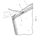
- FIG. 7 is a perspective view of a fastener being inserted into or removed from a groove of a panel of the modular wall panel system of FIG. 1 ;
- FIG. 8 is a perspective view of an inside corner portion of the modular wall panel system of FIG. 1 ;
- FIG. 9 is a perspective view of an outside corner portion of the modular wall panel system of FIG. 1 ;
- FIG. 10 is a perspective view of an end portion of the modular wall panel system of FIG. 1 .
- FIG. 1 shows a modular wall panel system 10 for use in industries such as healthcare, institutional, chain retail, chain restaurant, residential and contract/corporate interiors and the like that is constructed and assembled in accordance with an embodiment of the invention.
- the wall panel system 10 includes a number of rectangular or square decorative panels 12 arranged in an edge-to-edge manner to provide a finished wall surface.
- These individual panels 12 can be provided with substantially any desired surface finish.
- the panels 12 may be provided with simulated wood grain, abstracts, masonry surfaces and the like.
- the panels 12 may by provided with a wood veneer, a metal finish, high pressure laminates, solid colors, wood fiber surfaces, phosphate cement, fiber reinforced plastic or graphics.
- the panels 12 are positioned by connecting them to wall rails 16 with clips or fasteners 18 to insure that all of the panels within a given wall surface are properly positioned with respect to each other.
- the rails 16 are mounted on a supporting subwall, such as along studs 20 , such that a rail 16 extends along each vertical joint between adjacent vertical courses of panels 12 .
- the rails 16 are mounted such that a rail 16 extends along each horizontal joint between adjacent horizontal courses of panels 12 without departing from the scope of the invention.
- Each of the panels 12 is constructed utilizing a panel frame 22 which encompasses the perimeter of a composite structural core 24 .
- the wall rail 16 and the panel frame 22 each have a groove that accepts the fastener or clip 18 by interference or snap fit to attach the panel frame 22 to the wall rail 16 as will be more fully set forth below.
- the panels which can be identical for the most part, are an assembly of a flat, rigid board-like core 24 held in place in the panel frame 22 with one or more retainer springs 26 .
- the panel core 24 can comprise any suitable construction material and in one embodiment comprises a laminate of two outer face layers and an intermediate core 24 .
- the core 24 can be commercially available particle board that consists primarily of wood particles bonded together with known materials.
- the panel frame 22 comprises a plurality of frame members ( 22 A and 22 B) extending along each of the outer edges of the core 24 .
- Corner connectors 30 each located at a respective one of the corners of the frame assembly 22 and attached with suitable fasteners 32 thereby attaching adjacent ends of the frame members 22 together.
- Panels 12 of differing sizes can therefore easily be constructed by selecting the size of the core 24 and then cutting the panel frame 22 members to the required sizes and assembling the frame members using the corner connectors.
- the perimeter frame members 22 comprise extruded members of substantially uniform cross-section along their lengths preferably made from aluminum or a synthetic plastics material such as rigid polyvinyl chloride (PVC). However, the frame members 22 may be made from other materials.
- Each frame member 22 includes a spaced apart pair of generally parallel primary flanges 40 , 42 and a web 44 extending between and fixed to the primary flanges generally at right angles thereto to define a channel 46 , which channel receives therein a marginal edge portion of the panel core 24 .
- One flange 42 has a pair of groove-defining elements 50 forming a groove 52 configured to receive one or more mounting clips or fasteners 18 .
- the groove-defining elements 50 are desirably in the form of spaced secondary flanges which are generally orthogonal to the primary flanges 40 , 42 .
- the groove-defining elements 50 form the groove 52 along the longitudinal length of the frame member 22 .
- the groove 52 has a dove-tail shape that permits a clip or fastener 18 to be received in the groove with a snap fit.
- Each rail 16 includes a spaced apart pair of generally parallel groove-defining elements 60 connected by a web 61 extending between and fixed to the groove-defining elements.
- the rails 16 comprise extruded members of substantially uniform cross-section along their lengths preferably made from aluminum or a synthetic plastics material such as rigid polyvinyl chloride (PVC).
- PVC polyvinyl chloride
- the frame members may be made from other materials.
- the shape of the groove 62 formed by elements 60 permits the insertion of clips or fasteners 18 to secure the panels 12 yet permit the panels to be easily removed or reconfigured. As shown in FIG. 5 , groove 62 also has a dovetail configuration.
- the clips or fasteners 18 also provide a structure which accommodates a limited amount of panel expansion and contraction resulting from environmental temperature and humidity variations.
- the width of the web 61 is selected such that adjacent panels 12 are positioned with a close fit to form an attractive joint as illustrated in FIG. 6 . Consequently, this invention provides a building element being a joining clip or fastener 18 adapted to mount a panel to the rail, the joining clip or fastener 18 having means for cooperating with a groove of the rail 16 and means for connecting the joining clip or fastener 18 to a panel or bracket. It is also contemplated that a snap-on decorative trim may cover the joint between two adjacent panels.
- the joining clip or fastener 18 is symmetrical and has two substantially identical ends extending from a central body unit and is made of plastic such a polyvinyl chloride (PVC) or other suitable material. If desired, the joining clip or fastener 18 may have parts of varying resiliency, formed for example by multi-molding.
- the joining clip or fastener 18 may have protrusions 70 on each side of both ends of the clip or fastener 18 , especially a toothed protrusion, which is push or friction fit into the dove-tail shaped grooves 52 , 62 .
- a snap fit engagement is provided at both ends of the fastener with one end snap fit into the dovetail groove 52 of flange 42 formed on frame 22 , and the other end of the symmetrical clip 18 snap engaged in groove 62 of rail 16 .
- This method is illustrated in the drawings. It is intended that the material of the clip or fastener 18 and the close fit with the panel frame 22 and rail 16 provides a stable arrangement under normal conditions, but that the use of appropriate force will separate the clip or fastener 18 from the panel frame 22 and the rail 16 (for example, as seen in FIG. 7 ) when required, for example, so that the panel 12 can be repositioned.
- the rail 16 is adapted to join a first panel to a second panel with suitable transition portions as seen in FIGS. 8 and 9 .
- the rail may desirable form a decorative end trim as shown in FIG. 10 .
Abstract
Description
Claims (17)
Priority Applications (1)
| Application Number | Priority Date | Filing Date | Title |
|---|---|---|---|
| US13/417,945 US8322102B2 (en) | 2007-02-01 | 2012-03-12 | Wall panel system |
Applications Claiming Priority (4)
| Application Number | Priority Date | Filing Date | Title |
|---|---|---|---|
| US89877907P | 2007-02-01 | 2007-02-01 | |
| PCT/US2008/001182 WO2008094566A2 (en) | 2007-02-01 | 2008-01-30 | Wall panel system |
| US44923509A | 2009-07-29 | 2009-07-29 | |
| US13/417,945 US8322102B2 (en) | 2007-02-01 | 2012-03-12 | Wall panel system |
Related Parent Applications (3)
| Application Number | Title | Priority Date | Filing Date |
|---|---|---|---|
| PCT/US2008/001182 Continuation WO2008094566A2 (en) | 2007-02-01 | 2008-01-30 | Wall panel system |
| US12/449,235 Continuation US8151533B2 (en) | 2007-02-01 | 2008-01-30 | Wall panel system |
| US44923509A Continuation | 2007-02-01 | 2009-07-29 |
Publications (2)
| Publication Number | Publication Date |
|---|---|
| US20120167523A1 US20120167523A1 (en) | 2012-07-05 |
| US8322102B2 true US8322102B2 (en) | 2012-12-04 |
Family
ID=39674707
Family Applications (2)
| Application Number | Title | Priority Date | Filing Date |
|---|---|---|---|
| US12/449,235 Active 2028-04-23 US8151533B2 (en) | 2007-02-01 | 2008-01-30 | Wall panel system |
| US13/417,945 Active US8322102B2 (en) | 2007-02-01 | 2012-03-12 | Wall panel system |
Family Applications Before (1)
| Application Number | Title | Priority Date | Filing Date |
|---|---|---|---|
| US12/449,235 Active 2028-04-23 US8151533B2 (en) | 2007-02-01 | 2008-01-30 | Wall panel system |
Country Status (4)
| Country | Link |
|---|---|
| US (2) | US8151533B2 (en) |
| CA (1) | CA2676653C (en) |
| MX (1) | MX2009008183A (en) |
| WO (1) | WO2008094566A2 (en) |
Cited By (25)
| Publication number | Priority date | Publication date | Assignee | Title |
|---|---|---|---|---|
| US20120031036A1 (en) * | 2008-12-19 | 2012-02-09 | Jon Henrik Falk | Method for mountaing façade elements on a multi-storey building |
| US8584417B1 (en) * | 2012-06-06 | 2013-11-19 | Marlite, Inc. | Wall panel system |
| US8887459B2 (en) | 2012-05-19 | 2014-11-18 | Virginia Tech Intellectual Properties, Inc. | Modular wall assembly system |
| US8984838B2 (en) | 2011-11-09 | 2015-03-24 | Robert B. Bordener | Kit and assembly for compensating for coefficients of thermal expansion of decorative mounted panels |
| US8997413B2 (en) | 2013-08-15 | 2015-04-07 | Extraordinary Offerings, Ltd. | Modular booth system |
| US9097007B1 (en) | 2014-05-02 | 2015-08-04 | North Carolina State University | Panel assembly |
| US9181711B2 (en) | 2011-11-09 | 2015-11-10 | Robert B. Bordener | Bracket, kit and assembly for decorative mounted panels |
| USD753943S1 (en) | 2011-06-11 | 2016-04-19 | Dirtt Environmental Solutions, Ltd | Modular wall nesting system |
| USD754991S1 (en) | 2011-12-28 | 2016-05-03 | Dirtt Environmental Solutions, Ltd | Modular wall incorporating recessed, extendable furniture |
| US9518393B2 (en) | 2011-11-09 | 2016-12-13 | Robert B. Bordener | Kit and assembly for compensating for coefficients of thermal expansion of decorative mounted panels |
| US9943165B2 (en) | 2016-02-10 | 2018-04-17 | Dirtt Environmental Solutions, Ltd. | Embedded furniture having retractible legs with lighting |
| USRE46929E1 (en) | 2004-08-17 | 2018-07-03 | Dirtt Environmental Solutions, Ltd | Integrated reconfigurable wall system |
| US10041288B1 (en) | 2016-05-04 | 2018-08-07 | Jobsite Steel Manufacturing, LLC | Panel-in-panel wall system |
| US10822805B1 (en) | 2019-06-05 | 2020-11-03 | Germain LeBlanc | Wall connecting assembly and method for connecting a wall panel to a wall structure |
| US11053676B2 (en) | 2015-12-31 | 2021-07-06 | Cfs Concrete Forming Systems Inc. | Structure-lining apparatus with adjustable width and tool for same |
| US11085184B2 (en) | 2014-02-20 | 2021-08-10 | Dirtt Environmental Solutions Ltd. | Interface for mounting interchangable components |
| US11093087B2 (en) | 2016-06-10 | 2021-08-17 | Dirtt Environmental Solutions Ltd. | Glass substrates with touchscreen technology |
| USRE48722E1 (en) | 2004-08-17 | 2021-09-07 | Dirtt Environmental Solutions Ltd. | Integrated reconfigurable wall system |
| US11180915B2 (en) | 2017-04-03 | 2021-11-23 | Cfs Concrete Forming Systems Inc. | Longspan stay-in-place liners |
| US11240922B2 (en) | 2016-06-10 | 2022-02-01 | Dirtt Environmental Solutions Ltd. | Wall system with electronic device mounting assembly |
| US11512484B2 (en) | 2009-01-07 | 2022-11-29 | Cfs Concrete Forming Systems Inc. | Methods and apparatus for restoring, repairing, reinforcing and/or protecting structures using concrete |
| US11512483B2 (en) | 2017-12-22 | 2022-11-29 | Cfs Concrete Forming Systems Inc. | Snap-together standoffs for restoring, repairing, reinforcing, protecting, insulating and/or cladding structures |
| US11550178B2 (en) | 2016-07-08 | 2023-01-10 | Dirtt Environmental Solutions Inc. | Low-voltage smart glass |
| US11674322B2 (en) | 2019-02-08 | 2023-06-13 | Cfs Concrete Forming Systems Inc. | Retainers for restoring, repairing, reinforcing, protecting, insulating and/or cladding structures |
| US11674307B2 (en) | 2021-10-21 | 2023-06-13 | Saudi Arabian Oil Company | Modular non-metallic partitions |
Families Citing this family (21)
| Publication number | Priority date | Publication date | Assignee | Title |
|---|---|---|---|---|
| WO2011137530A1 (en) * | 2010-05-05 | 2011-11-10 | Eberhard Von Huene & Associates Inc. | Moveable and demountable wall panel system for butt-glazed wall panels |
| US8584414B1 (en) * | 2010-09-13 | 2013-11-19 | Stephen P. Hines | Reverse-perspective architecture |
| US9187913B2 (en) | 2012-01-19 | 2015-11-17 | Anenda Systems Inc. | Methods of fastening a wall panel to a wall, kits, and wall assemblies |
| US8695302B2 (en) * | 2012-03-22 | 2014-04-15 | Owens Corning Intellectual Capital, Llc | Air seal assembly |
| US9366020B2 (en) | 2012-11-06 | 2016-06-14 | Fc Modular, Llc | Modular building unit connection system |
| US9206827B2 (en) | 2012-11-20 | 2015-12-08 | Avery Dennison Corporation | Wall mount organization system |
| EP3108073A4 (en) * | 2014-02-20 | 2018-01-10 | DIRTT Environmental Solutions, Ltd. | Reconfigurable wall system |
| EP3152370A4 (en) | 2014-06-06 | 2018-01-10 | DIRTT Environmental Solutions, Ltd. | Straight and curved reconfigurable partition systems |
| US10738457B1 (en) | 2015-03-17 | 2020-08-11 | Thomas G. Hendry | Screen support assembly with wide lateral support efficiency |
| US10316508B1 (en) | 2015-03-17 | 2019-06-11 | Thomas G. Hendry | Screen support assembly with wide lateral support efficiency |
| USD856781S1 (en) * | 2018-02-23 | 2019-08-20 | Thomas G. Hendry | Corner bracket for a screen enclosure assembly |
| USD854710S1 (en) | 2015-03-17 | 2019-07-23 | Thomas G. Hendry | Structural post for a screen enclosure |
| USD879326S1 (en) | 2018-02-23 | 2020-03-24 | Thomas G. Hendry | Structural beam for a screen enclosure assembly |
| USD941499S1 (en) | 2018-02-23 | 2022-01-18 | Thomas G. Hendry | T-bracket for a screen enclosure assembly |
| KR101705134B1 (en) * | 2016-05-26 | 2017-02-09 | 이청종 | Prefabricated Walls for Interior and Mounting Method thereof |
| US10036156B1 (en) | 2017-01-31 | 2018-07-31 | Exterior Wall Systems Limited | Method of forming a three-dimensional structure having rigid wall panels |
| CA3036023C (en) * | 2018-03-05 | 2023-05-02 | Integrity Windows And Doors / Infinity Replacement Windows | Integrated fenestration wall assembly |
| CA189470S (en) * | 2018-07-13 | 2020-07-29 | Autostore Tech As | Grid pillar for a storage system |
| USD895147S1 (en) * | 2018-11-20 | 2020-09-01 | Mitsuhiro Oku | Transportable room |
| US11549260B2 (en) * | 2019-06-17 | 2023-01-10 | Jeffrey FATCHERIC | Wall panel fastening systems and methods |
| USD954301S1 (en) | 2020-01-20 | 2022-06-07 | Thomas G. Hendry | Structural beam for a screen enclosure |
Citations (68)
| Publication number | Priority date | Publication date | Assignee | Title |
|---|---|---|---|---|
| US3788021A (en) * | 1971-01-08 | 1974-01-29 | Blotzheim Ag Glutz Alphons | Interconnection system for structural elements |
| US4045932A (en) | 1976-07-08 | 1977-09-06 | Bogert Allen Z | Joint system for wall panel construction |
| US4086739A (en) | 1975-04-10 | 1978-05-02 | Hall Raymond L | Wall construction having panel attachment means |
| WO1981003194A1 (en) | 1980-04-29 | 1981-11-12 | I Andersson | A building structure |
| USRE30980E (en) | 1977-08-01 | 1982-06-29 | Gotaverken Aluminum AB | Wall system |
| US4356672A (en) | 1980-02-08 | 1982-11-02 | Vaughan Walls, Inc. | Partitioning system |
| WO1983001476A1 (en) | 1981-10-26 | 1983-04-28 | Ahlberg, Erik, Ola | Snap fastening device |
| GB2128707A (en) | 1982-10-25 | 1984-05-02 | Concepts International | Screening |
| US4535577A (en) | 1982-12-15 | 1985-08-20 | Global Upholstery Company Limited | Office panelling system |
| US4642957A (en) * | 1984-12-11 | 1987-02-17 | Edwards Troy C | Interior wall trim system |
| US4660339A (en) | 1985-11-20 | 1987-04-28 | Felix Paz | Wall system |
| US4680902A (en) | 1984-08-24 | 1987-07-21 | Stefnik William S | Unitized partition system |
| US4750310A (en) | 1986-11-26 | 1988-06-14 | Kawneer Company, Inc. | Storefront framing system |
| US4765111A (en) | 1987-06-18 | 1988-08-23 | Yoshinori Osawa | Assembly for mounting plates on wall |
| US4783941A (en) | 1986-10-27 | 1988-11-15 | William Loper | Prefabricated panel for building wall construction |
| US4905428A (en) | 1988-11-16 | 1990-03-06 | Sykes Christopher C | Partition structures and frame elements therefor |
| US4918879A (en) | 1987-05-29 | 1990-04-24 | Commercial And Architectural Products, Inc. | Merchandising wall structure including readily attachable and detachable panels and having plastic reveals |
| US4937992A (en) | 1989-06-21 | 1990-07-03 | Commercial And Architectural Products, Inc. | Scored panel |
| US4980998A (en) | 1989-01-06 | 1991-01-01 | Amstore Corporation | Wall system |
| US4996802A (en) | 1988-08-10 | 1991-03-05 | Finch Conservatories Limited | Snap fit building structure |
| US5058347A (en) | 1990-09-18 | 1991-10-22 | Herman Miller, Inc. | Panel connector system |
| WO1992005324A1 (en) | 1990-09-14 | 1992-04-02 | Erik Ahlberg | An arrangement for firmly, but detachably holding a first frame, panel or the like in a predetermined position relative to a second frame, panel or the like |
| US5138803A (en) | 1991-01-11 | 1992-08-18 | Commercial And Architectural Products, Inc. | Display panel assembly |
| WO1994001639A1 (en) | 1992-07-13 | 1994-01-20 | Haddock Robert M M | Mounting device for building surfaces |
| US5469683A (en) * | 1994-02-09 | 1995-11-28 | Kawneer Company, Inc. | Thermally insulating composite frame member with snap-in thermal isolator |
| US5481839A (en) * | 1992-09-09 | 1996-01-09 | Kawneer Company, Inc. | Glazed panel wall construction and method for assembly thereof |
| US5484067A (en) | 1992-08-07 | 1996-01-16 | Commercial And Architectural Products, Inc. | Slotted display wall panel |
| JPH0882013A (en) | 1994-09-06 | 1996-03-26 | Ebarisu:Kk | Plate material mounting device |
| US5579616A (en) | 1992-08-26 | 1996-12-03 | Farag; F. Aziz | Panel-securing system |
| US5644884A (en) | 1992-08-12 | 1997-07-08 | Commercial And Architectural Products, Inc. | Wall system providing an array of individual panels |
| US5644878A (en) | 1995-01-11 | 1997-07-08 | Sony Corporation | Reusable finish trim for prefabricated clean room wall system |
| US5692345A (en) | 1992-11-06 | 1997-12-02 | Toto Ltd. | Panel joining mechanism |
| US5694727A (en) | 1992-08-12 | 1997-12-09 | Commercial And Architectural Products, Inc. | Wall system providing an array of individual panels |
| DE29704548U1 (en) | 1997-03-13 | 1998-07-16 | Rixen Wolfgang | Fastening of surface elements in grooves of clamping profile bars |
| CA2198829A1 (en) | 1997-02-28 | 1998-08-28 | Global Upholstery Company | Lightweight panel structure |
| US5881518A (en) | 1993-10-15 | 1999-03-16 | Hollanding Inc. | Modular partition system |
| USD407832S (en) | 1997-05-30 | 1999-04-06 | Commercial And Architectural Products, Inc. | Support trim rail for panel wall system |
| US6141926A (en) | 1995-10-26 | 2000-11-07 | Tetrad Marketing/Sales Ltd. | Panel construction and connection system |
| US6161347A (en) | 1996-08-05 | 2000-12-19 | Haworth, Inc. | Panel arrangement |
| US6202377B1 (en) | 1998-12-23 | 2001-03-20 | Commercial And Architectural Products, Inc. | Panel attachment system |
| US6260324B1 (en) | 1996-06-07 | 2001-07-17 | Haworth, Inc. | Wall panel system |
| US6311441B1 (en) | 2000-03-13 | 2001-11-06 | The Artglo Company | Panel-based modular wall system |
| US6389778B1 (en) | 2000-05-02 | 2002-05-21 | Itec Steel Corporation | Modular wall panel structure |
| USD464153S1 (en) | 1998-12-23 | 2002-10-08 | Commercial And Architectural Products, Inc. | Support trim rail for panel wall system |
| US6491172B2 (en) | 2000-03-24 | 2002-12-10 | Commercial And Architectural Products, Inc. | Merchandising panel display system |
| USD477423S1 (en) | 2002-04-03 | 2003-07-15 | Commercial And Architectural Products, Inc. | Display panel |
| US20030189019A1 (en) | 2002-04-03 | 2003-10-09 | Campbell R. S. | Narrow groove display panel |
| USD482552S1 (en) | 2002-04-03 | 2003-11-25 | Commercial And Architectural Products, Inc. | Insert for a display panel |
| US6718717B2 (en) | 2000-02-25 | 2004-04-13 | Herman Miller Inc. | Modular wall panel and mounting member |
| WO2004055283A1 (en) | 2002-12-17 | 2004-07-01 | Jetstone Building Systems Pty Ltd | Improved building system |
| US20040139681A1 (en) | 2003-01-17 | 2004-07-22 | Kopish Andrew J. | Stiffener construction having a snap-on connector, for use with a wall panel shell in a wall system |
| US6775953B2 (en) | 2002-05-31 | 2004-08-17 | Hon Technology Inc. | Simplified wall panel |
| US6792727B2 (en) | 2002-09-12 | 2004-09-21 | Commercial And Architectural Products, Inc. | Curved wall panel system |
| US6799404B2 (en) | 2002-02-14 | 2004-10-05 | Daw Technologies, Inc. | Wall panel assembly and method of assembly |
| US6802168B1 (en) | 2002-12-03 | 2004-10-12 | Larry A. Minnick | Modular wall panel system with cooperatively tapered connector pins and slots |
| NL1023330C2 (en) | 2003-05-02 | 2004-11-09 | Snelwand B V | Wall construction kit comprising posts and e.g. plasterboard panels, has female coupling part joined to panel via support attached by adhesive |
| US6889477B1 (en) | 2000-10-06 | 2005-05-10 | Hni Technologies Inc. | Modular wall panel construction |
| US20050150616A1 (en) | 2003-12-18 | 2005-07-14 | Mcconnell Anthony | Covered pad for wall panel and manufacturing process |
| WO2005078204A1 (en) | 2004-02-13 | 2005-08-25 | Christopher James Hodgkinson | Panel jointing system |
| US6993875B2 (en) | 1996-10-11 | 2006-02-07 | Telezygology Inc. | Building elements |
| US20060059806A1 (en) | 2004-08-17 | 2006-03-23 | Geoff Gosling | Integrated reconfigurable wall system |
| US7036280B2 (en) * | 2002-06-05 | 2006-05-02 | X-Clad, Inc. | Tube-lock curtain wall system |
| USD537544S1 (en) | 2004-08-25 | 2007-02-27 | Marlite, Inc. | Wall panel |
| US20070284506A1 (en) | 2006-06-12 | 2007-12-13 | Bryan Benedict | Stay-in-place concrete footing forms |
| US7464509B1 (en) | 2005-07-15 | 2008-12-16 | Brown James C | Security wall |
| US7546716B1 (en) * | 2007-02-02 | 2009-06-16 | Armond Asadurian | Apparatus and method for constructing walls which include both exterior partition walls and also interior partition walls |
| US20100132293A1 (en) | 2008-12-01 | 2010-06-03 | Voegele Jr William P | Internal structural mullion for standing seam panel system |
| US7845120B2 (en) * | 2002-02-22 | 2010-12-07 | Technofirst | Device for fixing a sound-proofing panel on a wall |
Family Cites Families (1)
| Publication number | Priority date | Publication date | Assignee | Title |
|---|---|---|---|---|
| US6141925A (en) * | 1998-03-10 | 2000-11-07 | Steelcase Development Inc. | Clear wall panel system |
-
2008
- 2008-01-30 WO PCT/US2008/001182 patent/WO2008094566A2/en active Application Filing
- 2008-01-30 MX MX2009008183A patent/MX2009008183A/en active IP Right Grant
- 2008-01-30 US US12/449,235 patent/US8151533B2/en active Active
- 2008-01-30 CA CA2676653A patent/CA2676653C/en not_active Expired - Fee Related
-
2012
- 2012-03-12 US US13/417,945 patent/US8322102B2/en active Active
Patent Citations (79)
| Publication number | Priority date | Publication date | Assignee | Title |
|---|---|---|---|---|
| US3788021A (en) * | 1971-01-08 | 1974-01-29 | Blotzheim Ag Glutz Alphons | Interconnection system for structural elements |
| US4086739A (en) | 1975-04-10 | 1978-05-02 | Hall Raymond L | Wall construction having panel attachment means |
| US4045932A (en) | 1976-07-08 | 1977-09-06 | Bogert Allen Z | Joint system for wall panel construction |
| USRE30980E (en) | 1977-08-01 | 1982-06-29 | Gotaverken Aluminum AB | Wall system |
| US4356672A (en) | 1980-02-08 | 1982-11-02 | Vaughan Walls, Inc. | Partitioning system |
| WO1981003194A1 (en) | 1980-04-29 | 1981-11-12 | I Andersson | A building structure |
| WO1983001476A1 (en) | 1981-10-26 | 1983-04-28 | Ahlberg, Erik, Ola | Snap fastening device |
| GB2128707A (en) | 1982-10-25 | 1984-05-02 | Concepts International | Screening |
| US4535577A (en) | 1982-12-15 | 1985-08-20 | Global Upholstery Company Limited | Office panelling system |
| US4680902A (en) | 1984-08-24 | 1987-07-21 | Stefnik William S | Unitized partition system |
| US4642957A (en) * | 1984-12-11 | 1987-02-17 | Edwards Troy C | Interior wall trim system |
| US4660339A (en) | 1985-11-20 | 1987-04-28 | Felix Paz | Wall system |
| US4783941A (en) | 1986-10-27 | 1988-11-15 | William Loper | Prefabricated panel for building wall construction |
| US4750310A (en) | 1986-11-26 | 1988-06-14 | Kawneer Company, Inc. | Storefront framing system |
| US4918879A (en) | 1987-05-29 | 1990-04-24 | Commercial And Architectural Products, Inc. | Merchandising wall structure including readily attachable and detachable panels and having plastic reveals |
| US4765111A (en) | 1987-06-18 | 1988-08-23 | Yoshinori Osawa | Assembly for mounting plates on wall |
| US4996802A (en) | 1988-08-10 | 1991-03-05 | Finch Conservatories Limited | Snap fit building structure |
| US4905428A (en) | 1988-11-16 | 1990-03-06 | Sykes Christopher C | Partition structures and frame elements therefor |
| US4980998A (en) | 1989-01-06 | 1991-01-01 | Amstore Corporation | Wall system |
| US4937992A (en) | 1989-06-21 | 1990-07-03 | Commercial And Architectural Products, Inc. | Scored panel |
| WO1992005324A1 (en) | 1990-09-14 | 1992-04-02 | Erik Ahlberg | An arrangement for firmly, but detachably holding a first frame, panel or the like in a predetermined position relative to a second frame, panel or the like |
| US5058347A (en) | 1990-09-18 | 1991-10-22 | Herman Miller, Inc. | Panel connector system |
| US5138803A (en) | 1991-01-11 | 1992-08-18 | Commercial And Architectural Products, Inc. | Display panel assembly |
| WO1994001639A1 (en) | 1992-07-13 | 1994-01-20 | Haddock Robert M M | Mounting device for building surfaces |
| US5484067A (en) | 1992-08-07 | 1996-01-16 | Commercial And Architectural Products, Inc. | Slotted display wall panel |
| US5644884A (en) | 1992-08-12 | 1997-07-08 | Commercial And Architectural Products, Inc. | Wall system providing an array of individual panels |
| US5918437A (en) | 1992-08-12 | 1999-07-06 | Commercial And Architectural Products, Inc. | Wall system providing an array of individual panels |
| US5694727A (en) | 1992-08-12 | 1997-12-09 | Commercial And Architectural Products, Inc. | Wall system providing an array of individual panels |
| US5579616A (en) | 1992-08-26 | 1996-12-03 | Farag; F. Aziz | Panel-securing system |
| US5481839A (en) * | 1992-09-09 | 1996-01-09 | Kawneer Company, Inc. | Glazed panel wall construction and method for assembly thereof |
| US5692345A (en) | 1992-11-06 | 1997-12-02 | Toto Ltd. | Panel joining mechanism |
| US5881518A (en) | 1993-10-15 | 1999-03-16 | Hollanding Inc. | Modular partition system |
| US5469683A (en) * | 1994-02-09 | 1995-11-28 | Kawneer Company, Inc. | Thermally insulating composite frame member with snap-in thermal isolator |
| JPH0882013A (en) | 1994-09-06 | 1996-03-26 | Ebarisu:Kk | Plate material mounting device |
| US5644878A (en) | 1995-01-11 | 1997-07-08 | Sony Corporation | Reusable finish trim for prefabricated clean room wall system |
| US6141926A (en) | 1995-10-26 | 2000-11-07 | Tetrad Marketing/Sales Ltd. | Panel construction and connection system |
| US6260324B1 (en) | 1996-06-07 | 2001-07-17 | Haworth, Inc. | Wall panel system |
| US7055287B2 (en) | 1996-08-05 | 2006-06-06 | Haworth, Inc. | Panel arrangement |
| US6161347A (en) | 1996-08-05 | 2000-12-19 | Haworth, Inc. | Panel arrangement |
| US6658805B1 (en) | 1996-08-05 | 2003-12-09 | Haworth, Inc. | Panel arrangement |
| US6993875B2 (en) | 1996-10-11 | 2006-02-07 | Telezygology Inc. | Building elements |
| CA2198829A1 (en) | 1997-02-28 | 1998-08-28 | Global Upholstery Company | Lightweight panel structure |
| DE29704548U1 (en) | 1997-03-13 | 1998-07-16 | Rixen Wolfgang | Fastening of surface elements in grooves of clamping profile bars |
| USD407832S (en) | 1997-05-30 | 1999-04-06 | Commercial And Architectural Products, Inc. | Support trim rail for panel wall system |
| USD474549S1 (en) | 1998-12-23 | 2003-05-13 | Commercial And Architectural Products, Inc. | Support trim rail for panel wall system |
| US6427408B1 (en) | 1998-12-23 | 2002-08-06 | Commercial And Architectural Products, Inc. | Panel attachment system |
| USD466233S1 (en) | 1998-12-23 | 2002-11-26 | Commercial And Architectural Products, Inc. | Support trim rail for panel wall system |
| USD467670S1 (en) | 1998-12-23 | 2002-12-24 | Commercial And Architectural Products, Inc. | Support trim rail for panel wall system |
| USD479008S1 (en) | 1998-12-23 | 2003-08-26 | Commercial And Architectural Products, Inc. | Support trim rail for panel wall system |
| US6202377B1 (en) | 1998-12-23 | 2001-03-20 | Commercial And Architectural Products, Inc. | Panel attachment system |
| USD464153S1 (en) | 1998-12-23 | 2002-10-08 | Commercial And Architectural Products, Inc. | Support trim rail for panel wall system |
| USD465586S1 (en) | 1998-12-23 | 2002-11-12 | Commercial And Architectural Products, Inc. | Support trim rail for panel wall system |
| US6718717B2 (en) | 2000-02-25 | 2004-04-13 | Herman Miller Inc. | Modular wall panel and mounting member |
| US6311441B1 (en) | 2000-03-13 | 2001-11-06 | The Artglo Company | Panel-based modular wall system |
| US6491172B2 (en) | 2000-03-24 | 2002-12-10 | Commercial And Architectural Products, Inc. | Merchandising panel display system |
| US6389778B1 (en) | 2000-05-02 | 2002-05-21 | Itec Steel Corporation | Modular wall panel structure |
| US6889477B1 (en) | 2000-10-06 | 2005-05-10 | Hni Technologies Inc. | Modular wall panel construction |
| US6799404B2 (en) | 2002-02-14 | 2004-10-05 | Daw Technologies, Inc. | Wall panel assembly and method of assembly |
| US7845120B2 (en) * | 2002-02-22 | 2010-12-07 | Technofirst | Device for fixing a sound-proofing panel on a wall |
| USD482552S1 (en) | 2002-04-03 | 2003-11-25 | Commercial And Architectural Products, Inc. | Insert for a display panel |
| USD477423S1 (en) | 2002-04-03 | 2003-07-15 | Commercial And Architectural Products, Inc. | Display panel |
| US6772890B2 (en) | 2002-04-03 | 2004-08-10 | Commercial And Architectural Products, Inc. | Narrow groove display panel |
| USD486676S1 (en) | 2002-04-03 | 2004-02-17 | Commercial And Architectural Products, Inc. | Insert for a display panel |
| US20030189019A1 (en) | 2002-04-03 | 2003-10-09 | Campbell R. S. | Narrow groove display panel |
| US6775953B2 (en) | 2002-05-31 | 2004-08-17 | Hon Technology Inc. | Simplified wall panel |
| US7036280B2 (en) * | 2002-06-05 | 2006-05-02 | X-Clad, Inc. | Tube-lock curtain wall system |
| US6792727B2 (en) | 2002-09-12 | 2004-09-21 | Commercial And Architectural Products, Inc. | Curved wall panel system |
| US6802168B1 (en) | 2002-12-03 | 2004-10-12 | Larry A. Minnick | Modular wall panel system with cooperatively tapered connector pins and slots |
| WO2004055283A1 (en) | 2002-12-17 | 2004-07-01 | Jetstone Building Systems Pty Ltd | Improved building system |
| US20040139681A1 (en) | 2003-01-17 | 2004-07-22 | Kopish Andrew J. | Stiffener construction having a snap-on connector, for use with a wall panel shell in a wall system |
| NL1023330C2 (en) | 2003-05-02 | 2004-11-09 | Snelwand B V | Wall construction kit comprising posts and e.g. plasterboard panels, has female coupling part joined to panel via support attached by adhesive |
| US20050150616A1 (en) | 2003-12-18 | 2005-07-14 | Mcconnell Anthony | Covered pad for wall panel and manufacturing process |
| WO2005078204A1 (en) | 2004-02-13 | 2005-08-25 | Christopher James Hodgkinson | Panel jointing system |
| US20060059806A1 (en) | 2004-08-17 | 2006-03-23 | Geoff Gosling | Integrated reconfigurable wall system |
| USD537544S1 (en) | 2004-08-25 | 2007-02-27 | Marlite, Inc. | Wall panel |
| US7464509B1 (en) | 2005-07-15 | 2008-12-16 | Brown James C | Security wall |
| US20070284506A1 (en) | 2006-06-12 | 2007-12-13 | Bryan Benedict | Stay-in-place concrete footing forms |
| US7546716B1 (en) * | 2007-02-02 | 2009-06-16 | Armond Asadurian | Apparatus and method for constructing walls which include both exterior partition walls and also interior partition walls |
| US20100132293A1 (en) | 2008-12-01 | 2010-06-03 | Voegele Jr William P | Internal structural mullion for standing seam panel system |
Non-Patent Citations (10)
| Title |
|---|
| Canadian Office Action issued Feb. 23, 2012 in related Canadian Patent Application No. 2,676,653. |
| Canadian Office Action issued May 5, 2011 in related Canadian Application No. 2,676,653. |
| Fry Reglet Architectural Metals, Standard Detail Drawings, Sep. 29, 2005. |
| Fry Reglet Corporation Brochure, 4 pages, 2007. |
| http://www.fryreglet.com/graph.htm, Mar. 15, 2007. |
| http://www.fryreglet.com/graph-how.htm, Mar. 15, 2007. |
| http://www.fryreglet.com/products.htm, Mar. 15, 2007. |
| http://www.fryreglet.com/products-interior.htm, Mar. 15, 2007. |
| International Preliminary Report on Patentability mailed Aug. 13, 2009 for PCT/US2008/001182 filed Jan. 30, 2008. |
| International Search Report and Written Opinion mailed Nov. 25, 2008 for PCT/US2008/001182 filed Jan. 30, 2008. |
Cited By (35)
| Publication number | Priority date | Publication date | Assignee | Title |
|---|---|---|---|---|
| USRE48722E1 (en) | 2004-08-17 | 2021-09-07 | Dirtt Environmental Solutions Ltd. | Integrated reconfigurable wall system |
| USRE47693E1 (en) | 2004-08-17 | 2019-11-05 | Dirtt Environmental Solutions, Ltd. | Integrated reconfigurable wall system |
| USRE47132E1 (en) | 2004-08-17 | 2018-11-20 | Dirtt Environmental Solutions, Ltd | Integrated reconfigurable wall system |
| USRE46929E1 (en) | 2004-08-17 | 2018-07-03 | Dirtt Environmental Solutions, Ltd | Integrated reconfigurable wall system |
| US20120031036A1 (en) * | 2008-12-19 | 2012-02-09 | Jon Henrik Falk | Method for mountaing façade elements on a multi-storey building |
| US8695308B2 (en) * | 2008-12-19 | 2014-04-15 | Brunkeberg Systems Ab | Method for mounting façade elements on a multi-storey building |
| US11512484B2 (en) | 2009-01-07 | 2022-11-29 | Cfs Concrete Forming Systems Inc. | Methods and apparatus for restoring, repairing, reinforcing and/or protecting structures using concrete |
| USD753943S1 (en) | 2011-06-11 | 2016-04-19 | Dirtt Environmental Solutions, Ltd | Modular wall nesting system |
| US9347218B2 (en) | 2011-06-11 | 2016-05-24 | Dirtt Environmental Solutions, Ltd. | Modular wall nesting system |
| US9518393B2 (en) | 2011-11-09 | 2016-12-13 | Robert B. Bordener | Kit and assembly for compensating for coefficients of thermal expansion of decorative mounted panels |
| US9650790B2 (en) | 2011-11-09 | 2017-05-16 | Robert B. Bordener | Bracket, kit and assembly for decorative mounted panels |
| US9181711B2 (en) | 2011-11-09 | 2015-11-10 | Robert B. Bordener | Bracket, kit and assembly for decorative mounted panels |
| US8984838B2 (en) | 2011-11-09 | 2015-03-24 | Robert B. Bordener | Kit and assembly for compensating for coefficients of thermal expansion of decorative mounted panels |
| US10920418B2 (en) | 2011-12-28 | 2021-02-16 | Dirtt Environmental Solutions, Ltd | Modular walls incorporating recessed, extendable furniture |
| USD754991S1 (en) | 2011-12-28 | 2016-05-03 | Dirtt Environmental Solutions, Ltd | Modular wall incorporating recessed, extendable furniture |
| US8887459B2 (en) | 2012-05-19 | 2014-11-18 | Virginia Tech Intellectual Properties, Inc. | Modular wall assembly system |
| US8584417B1 (en) * | 2012-06-06 | 2013-11-19 | Marlite, Inc. | Wall panel system |
| US8997413B2 (en) | 2013-08-15 | 2015-04-07 | Extraordinary Offerings, Ltd. | Modular booth system |
| US11085184B2 (en) | 2014-02-20 | 2021-08-10 | Dirtt Environmental Solutions Ltd. | Interface for mounting interchangable components |
| US9097007B1 (en) | 2014-05-02 | 2015-08-04 | North Carolina State University | Panel assembly |
| US11499308B2 (en) | 2015-12-31 | 2022-11-15 | Cfs Concrete Forming Systems Inc. | Structure-lining apparatus with adjustable width and tool for same |
| US11053676B2 (en) | 2015-12-31 | 2021-07-06 | Cfs Concrete Forming Systems Inc. | Structure-lining apparatus with adjustable width and tool for same |
| US10058170B2 (en) | 2016-02-10 | 2018-08-28 | Dirtt Environmental Solutions, Ltd | Modular walls with embedded furniture and opposing feature |
| US9943165B2 (en) | 2016-02-10 | 2018-04-17 | Dirtt Environmental Solutions, Ltd. | Embedded furniture having retractible legs with lighting |
| US10041288B1 (en) | 2016-05-04 | 2018-08-07 | Jobsite Steel Manufacturing, LLC | Panel-in-panel wall system |
| US11240922B2 (en) | 2016-06-10 | 2022-02-01 | Dirtt Environmental Solutions Ltd. | Wall system with electronic device mounting assembly |
| US11093087B2 (en) | 2016-06-10 | 2021-08-17 | Dirtt Environmental Solutions Ltd. | Glass substrates with touchscreen technology |
| US11550178B2 (en) | 2016-07-08 | 2023-01-10 | Dirtt Environmental Solutions Inc. | Low-voltage smart glass |
| US11180915B2 (en) | 2017-04-03 | 2021-11-23 | Cfs Concrete Forming Systems Inc. | Longspan stay-in-place liners |
| US11821204B2 (en) | 2017-04-03 | 2023-11-21 | Cfs Concrete Forming Systems Inc. | Longspan stay-in-place liners |
| US11512483B2 (en) | 2017-12-22 | 2022-11-29 | Cfs Concrete Forming Systems Inc. | Snap-together standoffs for restoring, repairing, reinforcing, protecting, insulating and/or cladding structures |
| US11761220B2 (en) | 2017-12-22 | 2023-09-19 | Cfs Concrete Forming Systems Inc. | Snap-together standoffs for restoring, repairing, reinforcing, protecting, insulating and/or cladding structures |
| US11674322B2 (en) | 2019-02-08 | 2023-06-13 | Cfs Concrete Forming Systems Inc. | Retainers for restoring, repairing, reinforcing, protecting, insulating and/or cladding structures |
| US10822805B1 (en) | 2019-06-05 | 2020-11-03 | Germain LeBlanc | Wall connecting assembly and method for connecting a wall panel to a wall structure |
| US11674307B2 (en) | 2021-10-21 | 2023-06-13 | Saudi Arabian Oil Company | Modular non-metallic partitions |
Also Published As
| Publication number | Publication date |
|---|---|
| US8151533B2 (en) | 2012-04-10 |
| WO2008094566A3 (en) | 2009-01-15 |
| WO2008094566A2 (en) | 2008-08-07 |
| US20100050548A1 (en) | 2010-03-04 |
| CA2676653C (en) | 2013-05-21 |
| CA2676653A1 (en) | 2008-08-07 |
| US20120167523A1 (en) | 2012-07-05 |
| MX2009008183A (en) | 2010-02-17 |
Similar Documents
| Publication | Publication Date | Title |
|---|---|---|
| US8322102B2 (en) | Wall panel system | |
| US10900227B2 (en) | Housing construction system | |
| US8011849B2 (en) | Corner connector | |
| US5737893A (en) | Panel construction and connection system | |
| US5822935A (en) | Solid-core wall system | |
| US6634077B2 (en) | Combined connecting and alignment method for composite fiber building panels | |
| US7810294B2 (en) | Housing construction system | |
| US5803146A (en) | Modular partition system | |
| US6141926A (en) | Panel construction and connection system | |
| US8776376B2 (en) | Method of forming paneled corners | |
| US20060010804A1 (en) | Modular frame area floor covering | |
| US6817153B2 (en) | Cornerboard assembly | |
| JP2019518890A (en) | Assembled wall for interior and construction method thereof | |
| US8136321B1 (en) | Decorative ceiling/wall panel | |
| CA2237210C (en) | Panel construction and connection system | |
| US20160273217A1 (en) | Ceiling system | |
| US8079186B2 (en) | Soffit system | |
| WO2005118273A1 (en) | Modular frame area floor covering | |
| JP7312652B2 (en) | Building ceiling and its construction method | |
| CA2188858C (en) | Panel construction and connection system | |
| EP3715553B1 (en) | Assembly of building panels with coupling elements | |
| CN116194015A (en) | Combined decorative building block | |
| AU628089B2 (en) | Modular panelling system | |
| JPH1182438A (en) | Indoor installed product and connecting tool used for assembling the same | |
| JP2017122371A (en) | Partition mounting member and partition structure |
Legal Events
| Date | Code | Title | Description |
|---|---|---|---|
| AS | Assignment |
Owner name: FIRST NATIONAL BANK OF PENNSYLVANIA, PENNSYLVANIA Free format text: AMENDED AND RESTATED PATENT, TRADEMARK AND COPYRIGHT SECUIRTY AGREEMENT;ASSIGNORS:MARLITE, INC.;MARLITE EXPORT SALES, INC.;RETAIL SYSTEMS & SOLUTIONS, INC.;REEL/FRAME:028917/0325 Effective date: 20120831 |
|
| STCF | Information on status: patent grant |
Free format text: PATENTED CASE |
|
| AS | Assignment |
Owner name: FIRST NATIONAL BANK OF PENNSYLVANIA, PENNSYLVANIA Free format text: SECURITY AGREEMENT;ASSIGNORS:MARLITE, INC.;MARLITE EXPORT SALES, INC.;RETAIL SYSTEMS AND SOLUTIONS, INC.;REEL/FRAME:030812/0072 Effective date: 20130712 |
|
| AS | Assignment |
Owner name: PNC BANK, NATIONAL ASSOCIATION, PENNSYLVANIA Free format text: SECURITY INTEREST;ASSIGNOR:MARLITE, INC.;REEL/FRAME:034706/0308 Effective date: 20150113 |
|
| AS | Assignment |
Owner name: FIRST NATIONAL BANK OF PENNSYLVANIA, PENNSYLVANIA Free format text: CORRECTIVE ASSIGNMENT TO CORRECT THE APPLICATION NUMBER 13/703,398 PREVIOUSLY RECORDED AT REEL: 030812 FRAME: 0072. ASSIGNOR(S) HEREBY CONFIRMS THE SECURITY INTEREST;ASSIGNORS:MARLITE, INC.;MARLITE EXPORT SALES, INC.;RETAIL SYSTEMS AND SOLUTIONS, INC.;REEL/FRAME:034853/0616 Effective date: 20130712 |
|
| AS | Assignment |
Owner name: MARLITE, INC., OHIO Free format text: RELEASE BY SECURED PARTY;ASSIGNOR:FIRST NATIONAL BANK OF PENNSYLVANIA;REEL/FRAME:034866/0064 Effective date: 20150112 Owner name: RETAIL SYSTEMS AND SOLUTIONS, INC., OHIO Free format text: RELEASE BY SECURED PARTY;ASSIGNOR:FIRST NATIONAL BANK OF PENNSYLVANIA;REEL/FRAME:034866/0064 Effective date: 20150112 Owner name: MARLITE EXPORT SALES, INC., OHIO Free format text: RELEASE BY SECURED PARTY;ASSIGNOR:FIRST NATIONAL BANK OF PENNSYLVANIA;REEL/FRAME:034866/0064 Effective date: 20150112 Owner name: MARLITE EXPORT SALES, INC., OHIO Free format text: RELEASE BY SECURED PARTY;ASSIGNOR:FIRST NATIONAL BANK OF PENNSYLVANIA;REEL/FRAME:034865/0974 Effective date: 20150112 Owner name: MARLITE, INC., OHIO Free format text: RELEASE BY SECURED PARTY;ASSIGNOR:FIRST NATIONAL BANK OF PENNSYLVANIA;REEL/FRAME:034865/0974 Effective date: 20150112 Owner name: RETAIL SYSTEMS AND SOLUTIONS, INC., OHIO Free format text: RELEASE BY SECURED PARTY;ASSIGNOR:FIRST NATIONAL BANK OF PENNSYLVANIA;REEL/FRAME:034865/0974 Effective date: 20150112 |
|
| FEPP | Fee payment procedure |
Free format text: PAT HOLDER NO LONGER CLAIMS SMALL ENTITY STATUS, ENTITY STATUS SET TO UNDISCOUNTED (ORIGINAL EVENT CODE: STOL); ENTITY STATUS OF PATENT OWNER: LARGE ENTITY |
|
| FPAY | Fee payment |
Year of fee payment: 4 |
|
| MAFP | Maintenance fee payment |
Free format text: PAYMENT OF MAINTENANCE FEE, 8TH YEAR, LARGE ENTITY (ORIGINAL EVENT CODE: M1552); ENTITY STATUS OF PATENT OWNER: LARGE ENTITY Year of fee payment: 8 |