US8313004B2 - Can shell and double-seamed can end - Google Patents
Can shell and double-seamed can end Download PDFInfo
- Publication number
- US8313004B2 US8313004B2 US12/904,532 US90453210A US8313004B2 US 8313004 B2 US8313004 B2 US 8313004B2 US 90453210 A US90453210 A US 90453210A US 8313004 B2 US8313004 B2 US 8313004B2
- Authority
- US
- United States
- Prior art keywords
- wall
- countersink
- panel wall
- inches
- radius
- Prior art date
- Legal status (The legal status is an assumption and is not a legal conclusion. Google has not performed a legal analysis and makes no representation as to the accuracy of the status listed.)
- Expired - Lifetime
Links
Images


Classifications
-
- B—PERFORMING OPERATIONS; TRANSPORTING
- B65—CONVEYING; PACKING; STORING; HANDLING THIN OR FILAMENTARY MATERIAL
- B65D—CONTAINERS FOR STORAGE OR TRANSPORT OF ARTICLES OR MATERIALS, e.g. BAGS, BARRELS, BOTTLES, BOXES, CANS, CARTONS, CRATES, DRUMS, JARS, TANKS, HOPPERS, FORWARDING CONTAINERS; ACCESSORIES, CLOSURES, OR FITTINGS THEREFOR; PACKAGING ELEMENTS; PACKAGES
- B65D15/00—Containers having bodies formed by interconnecting or uniting two or more rigid, or substantially rigid, sections made of different materials
-
- B—PERFORMING OPERATIONS; TRANSPORTING
- B65—CONVEYING; PACKING; STORING; HANDLING THIN OR FILAMENTARY MATERIAL
- B65D—CONTAINERS FOR STORAGE OR TRANSPORT OF ARTICLES OR MATERIALS, e.g. BAGS, BARRELS, BOTTLES, BOXES, CANS, CARTONS, CRATES, DRUMS, JARS, TANKS, HOPPERS, FORWARDING CONTAINERS; ACCESSORIES, CLOSURES, OR FITTINGS THEREFOR; PACKAGING ELEMENTS; PACKAGES
- B65D17/00—Rigid or semi-rigid containers specially constructed to be opened by cutting or piercing, or by tearing of frangible members or portions
- B65D17/06—Integral, or permanently secured, end or side closures
- B65D17/08—Closures secured by folding or rolling and pressing
-
- B—PERFORMING OPERATIONS; TRANSPORTING
- B21—MECHANICAL METAL-WORKING WITHOUT ESSENTIALLY REMOVING MATERIAL; PUNCHING METAL
- B21D—WORKING OR PROCESSING OF SHEET METAL OR METAL TUBES, RODS OR PROFILES WITHOUT ESSENTIALLY REMOVING MATERIAL; PUNCHING METAL
- B21D51/00—Making hollow objects
- B21D51/16—Making hollow objects characterised by the use of the objects
- B21D51/26—Making hollow objects characterised by the use of the objects cans or tins; Closing same in a permanent manner
- B21D51/30—Folding the circumferential seam
- B21D51/32—Folding the circumferential seam by rolling
-
- B—PERFORMING OPERATIONS; TRANSPORTING
- B65—CONVEYING; PACKING; STORING; HANDLING THIN OR FILAMENTARY MATERIAL
- B65D—CONTAINERS FOR STORAGE OR TRANSPORT OF ARTICLES OR MATERIALS, e.g. BAGS, BARRELS, BOTTLES, BOXES, CANS, CARTONS, CRATES, DRUMS, JARS, TANKS, HOPPERS, FORWARDING CONTAINERS; ACCESSORIES, CLOSURES, OR FITTINGS THEREFOR; PACKAGING ELEMENTS; PACKAGES
- B65D7/00—Containers having bodies formed by interconnecting or uniting two or more rigid, or substantially rigid, components made wholly or mainly of metal
- B65D7/12—Containers having bodies formed by interconnecting or uniting two or more rigid, or substantially rigid, components made wholly or mainly of metal characterised by wall construction or by connections between walls
- B65D7/34—Containers having bodies formed by interconnecting or uniting two or more rigid, or substantially rigid, components made wholly or mainly of metal characterised by wall construction or by connections between walls with permanent connections between walls
- B65D7/36—Containers having bodies formed by interconnecting or uniting two or more rigid, or substantially rigid, components made wholly or mainly of metal characterised by wall construction or by connections between walls with permanent connections between walls formed by rolling, or by rolling and pressing
-
- B—PERFORMING OPERATIONS; TRANSPORTING
- B65—CONVEYING; PACKING; STORING; HANDLING THIN OR FILAMENTARY MATERIAL
- B65D—CONTAINERS FOR STORAGE OR TRANSPORT OF ARTICLES OR MATERIALS, e.g. BAGS, BARRELS, BOTTLES, BOXES, CANS, CARTONS, CRATES, DRUMS, JARS, TANKS, HOPPERS, FORWARDING CONTAINERS; ACCESSORIES, CLOSURES, OR FITTINGS THEREFOR; PACKAGING ELEMENTS; PACKAGES
- B65D7/00—Containers having bodies formed by interconnecting or uniting two or more rigid, or substantially rigid, components made wholly or mainly of metal
- B65D7/42—Details of metal walls
- B65D7/44—Reinforcing or strengthening parts or members
-
- B—PERFORMING OPERATIONS; TRANSPORTING
- B65—CONVEYING; PACKING; STORING; HANDLING THIN OR FILAMENTARY MATERIAL
- B65D—CONTAINERS FOR STORAGE OR TRANSPORT OF ARTICLES OR MATERIALS, e.g. BAGS, BARRELS, BOTTLES, BOXES, CANS, CARTONS, CRATES, DRUMS, JARS, TANKS, HOPPERS, FORWARDING CONTAINERS; ACCESSORIES, CLOSURES, OR FITTINGS THEREFOR; PACKAGING ELEMENTS; PACKAGES
- B65D2517/00—Containers specially constructed to be opened by cutting, piercing or tearing of wall portions, e.g. preserving cans or tins
- B65D2517/0001—Details
- B65D2517/0058—Other details of container end panel
- B65D2517/0059—General cross-sectional shape of container end panel
- B65D2517/0061—U-shaped
- B65D2517/0062—U-shaped and provided with an additional U-shaped peripheral channel
Definitions
- This invention relates to the construction or forming of a sheet metal or aluminum can shell and can end having a peripheral rim or crown which is double-seamed to the upper edge portion of a sheet metal or aluminum can body.
- a can end is formed from a drawn sheet metal can shell, for example, a shell produced by tooling as disclosed in applicant's U.S. Pat. No. 5,857,374 the disclosure of which is herein incorporated by reference.
- the formed can shell includes a circular center panel which extends to a panel wall which extends to or also forms the inner wall of a reinforcing rib or countersink having a U-shaped cross-sectional configuration.
- the countersink is connected by a generally frusto-conical chuckwall to an annular crown which is formed with a peripheral curl.
- the center panel of the shell is commonly provided with an E-Z open tab, and after the can body is filled with a beverage, the peripherally curled crown of the shell is double-seamed to the upper end portion of the can body.
- the can body When the can body is filled with a carbonated beverage or a beverage which must be pasteurized at a high temperature, it is essential for the can end to have a substantial buckle strength to withstand the pressurized beverage, for example, a buckle strength of at least 90 psi.
- a buckle strength Such resistance to “buckle” pressure and “rock” pressure is described in detail in U.S. Pat. No. 4,448,322, the disclosure of which is incorporated by reference.
- 6,499,622 disclose various forms and configurations of can shells and can ends and the various dimensions and configurations which have been proposed or used for increasing the buckle strength of a can end and/or reducing the metal in the can end.
- published PCT application No. WO 98/34743 discloses a modification of the can shell and can end disclosed in above-mentioned U.S. Pat. No. 6,065,634.
- it is desirable to form the can shell so that there is minimal modifications required to the extensive tooling existing in the field for adding the E-Z open tabs to the can shells and for double-seaming the can shells to the can bodies. While some of the can shells and can ends disclosed in the above patents provide some of desirable structural features, none of the patents provide all of the features.
- the present invention is directed to an improved sheet metal shell and can end and a method of forming the can end which provides the desirable features and advantages mentioned above, including a significant reduction in the blank diameter for forming a can shell and a significant increase in strength/weight ratio of the resulting can end.
- a can shell and can end formed in accordance with the invention not only increases the buckle strength of the can end but also minimizes the changes or modifications in the existing tooling for adding E-Z open tabs to the can shells and for double-seaming the can shells to the can bodies.
- the can shell and can end are formed with an overall height between the crown and the countersink of less than 0.240 inch and preferably less than 0.230 inch, and the countersink has a generally cylindrical outer wall and an inner wall connected to a curved panel wall.
- a generally frusto-conical chuckwall extends from the outer wall of the countersink to the inner wall of the crown and has an upper wall portion extending at an angle of at least 16° relative to the center axis of the shell, and preferably between 25° and 30°.
- the countersink may have a generally flat bottom wall or inclined inner wall which connects with the countersink outer wall with a small radius substantially less than the radial width of the bottom wall, and the inside width of the countersink at its bottom is less than the radius of the panel wall.
- a can shell and can end have some of the above structure and with the junction of a lower wall portion of the chuckwall and the outer countersink wall being substantially below the center panel.
- the lower wall portion of the countersink extends at an angle less than the angle of the upper wall portion relative to the center axis and is connected to the upper wall portion by a short wall portion which provides the chuckwall with a break or kick or a slight S-curved configuration.
- the countersink has a radius of curvature substantially smaller than the radius of curvature or radial width of the panel wall, and the inner bottom width of the countersink is also less than the radius or radial width of the panel wall, and preferably less than 0.035 inch.
- the countersink has an inclined bottom wall portion, and the panel wall has an inclined flat wall portion.
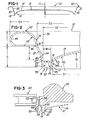
- FIG. 1 is a vertical cross-section through a sheet metal can shell formed in accordance with the invention
- FIG. 2 is an enlarged fragmentary section of the can shell in FIG. 1 and showing the configuration of one embodiment
- FIG. 3 is a smaller fragmentary section of the can shell of FIG. 2 and showing the can shell becoming a can end with a double-seaming chuck and a first stage roller;
- FIG. 4 is a fragmentary section similar to FIG. 3 and showing a double-seamed can end with the chuck and a second stage roller;
- FIG. 5 is an enlarged fragmentary section of the double-seamed can end shown in FIG. 4 and with a fragment of the modified double-seaming chuck;
- FIG. 6 is a section similar to FIG. 1 and showing a double-seamed can end formed in accordance with the invention
- FIG. 7 is an enlarged fragmentary section similar to FIG. 2 and showing a can shell formed in accordance with a modification of the invention
- FIG. 8 is an enlarged fragmentary section similar to FIG. 5 and showing the can shell of FIG. 7 double-seamed onto a can body;
- FIG. 9 is an enlarged fragmentary section similar to FIG. 7 and showing a can shell formed in accordance with another modification of the invention.
- FIG. 10 illustrates the stacking and nesting of can shells formed as shown in FIG. 9 ;
- FIG. 11 is an enlarged fragmentary section of the chuckwall of the can shell shown in FIG. 9 .
- FIG. 12 is an enlarged fragmentary section similar to FIG. 9 and showing a can shell formed in accordance with another modification of the invention.
- FIG. 13 is an enlarged fragmentary section similar to FIG. 12 and showing a can shell formed in accordance with a further modification of the invention.
- FIG. 1 illustrates a one-piece shell 10 which is formed from a substantially circular blank of sheet metal or aluminum, preferably having a thickness of about 0.0085 inch and a blank diameter of about 2.705 inches.
- the shell 10 has a center axis 11 and includes a slightly crowned center panel 12 with an annular portion 14 extending to a curved panel wall 16 .
- the center panel wall portion 14 and panel wall 16 may be formed by a series of blended curved walls having radii wherein R 1 is 1.489 inch, R 2 is 0.321 inch, R 3 is 0.031 inch, and R 4 is 0.055 inch.
- the curved panel wall 16 has a bottom inner diameter D 1 of about 1.855 inch.
- the curved panel wall 16 with the radius R 4 extends from an inner wall 17 of a reinforcing rib or countersink 18 having a U-shaped cross-sectional configuration and including a flat annular bottom wall 22 and a generally cylindrical outer wall 24 having an inner diameter D 2 , for example, of about 1.957 inches.
- the flat bottom wall 22 of the countersink 18 is connected to the inner panel wall 16 and the outer countersink wall 24 by curved corner walls 26 each having an inner radius R 5 of about 0.010 inch.
- the radial width W of the flat bottom wall 22 is preferably about 0.022 inch so that the inner bottom width W 1 of the countersink 18 is about 0.042 inch.
- the outer wall 24 of the countersink 18 connects with a generally frusto-conical chuckwall 32 by a curved wall 34 having a radius R 6 of about 0.054 inch.
- the chuckwall 32 extends at an angle A 1 of at least 16° with respect to the center axis 11 or a vertical reference line 36 which is parallel to the center axis 11 of the shell. Preferably, the angle A 1 is between 25° and 30° and on the order of 29°.
- the upper end of the chuckwall 32 connects with the bottom of a curved inner wall 38 of a rounded crown 42 having a curled outer wall 44 .
- the inner wall 38 of the crown 42 has a radius R 7 of about 0.070 inch, the inner diameter D 3 at the bottom of the curved inner wall 38 is about 2.039 inch, and the outer diameter D 4 of the curled outer wall 44 is about 2.340 inches.
- the height C of the curled outer wall 44 is within the range of 0.075 inch and 0.095 inch and is preferably about 0.079 inch.
- the depth D from the bottom of the outer curled wall 44 or the junction 46 of the chuckwall 32 and the inner crown wall 38 to the inner surface of the countersink bottom wall 22 is within the range between 0.108 inch and 0.148 inch, and preferably about 0.126 inch.
- the junction 47 or the center point for the radius R 6 has a depth G of about 0.079 from the junction 46 or bottom of the curled outer wall 44 of the crown 42 .
- FIG. 3 shows the crown 42 of the shell 10 being double-seamed onto an upper peripheral end portion 48 of a sheet metal or aluminum can body 50 .
- the double-seaming operation is performed between a rotating double-seaming circular chuck 55 which engages the shell 10 and has an outer surface 58 which may be slightly tapered between an angle of 0° and 10° with respect to the center axis of the chuck 55 and the common center axis 11 of the shell 10 .
- the surface 58 has a slight taper of about 4° and is engaged by the inner wall 38 of the crown 42 in response to radially inward movement of a first stage double-seaming roller 60 while the can body 50 and its contents and the shell 10 are rotating or spinning with the chuck 55 .
- the chuck 55 also has a frusto-conical surface 62 which mates with and engages the frusto-conical chuckwall 32 of the shell 10 , and a downwardly projecting annular lip portion 64 of the chuck 55 extends into the countersink 18 and has a bottom surface 66 ( FIG. 5 ) and a cylindrical outer surface 68 which engage the bottom wall 22 and the outer wall 24 of the countersink 18 , respectively.
- FIGS. 4 & 5 illustrates the completion of the double-seaming operation to form a double-seamed crown 70 between the rotating chuck 55 and a second stage double-seaming roller 72 which also moves radially inwardly while the chuck 55 , shell 10 and can body 50 are spinning to convert the shell 10 into a can end 75 which is positively attached and sealed to the upper end portion 48 of the can body 50 .
- the double-seamed rim or crown 70 has an inner wall 74 which is formed from the inner wall 38 of the shell crown 42 and also has an outer wall 76 formed from the shell crown 42 including the outer curled wall 44 .
- the double-seamed crown 70 has a height H 2 within the range between 0.090 inch and 0.110 inch and preferably about 0.100 inch.
- the can end 75 has an overall height H 1 between the top of the crown 70 and the bottom of the countersink 18 within the range of 0.170 inch and 0.240 inch, and preferably about 0.235 inch. Since the can end 75 has the same cross-sectional configuration as the shell 10 with the exception of the double-seamed crown 70 , the same common reference numbers are used in FIGS. 4-6 for the common structure.
- the center portion of the center panel 12 defines a plane 80 which substantially intersects the junction 46 of the chuckwall 32 with the inner wall 74 of the double-seamed crown 70 .
- the E-Z open tab has been omitted from FIG. 6 for purposes of clarity and simplification and since the E-Z open tab forms no part of the present invention.
- FIGS. 7 & 8 show another embodiment or modification of the invention including a can shell ( FIG. 7 ) and a double-seamed can end ( FIG. 8 ).
- a can shell 10 ′ has a center axis which is the same as the axis 11 and includes a circular center panel 12 ′ connected to a peripheral curved panel wall 16 ′ which connects with an inclined inner wall 17 ′ of a countersink 18 ′ having a U-shaped cross-sectional configuration.
- the countersink has a generally cylindrical outer wall 24 ′ which extends at an angle less than 10° and connects with a chuckwall having a frusto-conical upper wall portion 32 ′ and a slightly curved lower wall portion 34 ′.
- the wall portions 32 ′ and 34 ′ are connected by a kick or generally vertical short riser portion 35 ′ having relatively sharp inside and outside radii, for example, on the order of 0.020 inch.
- the upper chuckwall portion 32 ′ is connected by a curved wall 37 ′ to the inner curved wall 38 ′ of a crown 42 ′ having a curved outer wall 44 ′.
- the inner wall 38 ′ of the crown 42 ′ connects with the upper chuckwall portion 32 ′ at a junction 46 ′, and the outer wall 24 ′ of the countersink 18 ′ connects with the lower chuckwall portion 34 ′ at a junction 47 ′.
- the vertical height G 1 from the bottom of the countersink 18 ′ to the kick or riser portion 35 ′ is about 0.086.
- the radius R 10 is about 0.051 inch, and the lower wall portion 34 ′ extends at an angle A 3 of about 15°.
- the countersink 18 ′ has a radius R 9 of about 0.009 to 0.011 inch.
- Other approximate dimensions and angles for the shell 10 ′ shown in FIG. 7 are as follows:
- the particular cross-sectional configuration of the can shell 10 ′ has been found to provide performance results superior to the performance results provided by the can shell 10 .
- the details of the configuration of the can shell 10 ′ include a chuckwall upper wall portion 32 ′ having an angle A 2 relative to the center axis of at least 16° and preferably within the range of 25° to 30°.
- the lower wall portion 34 ′ of the chuckwall forms an angle A 3 which is about 15°.
- the inner wall 38 ′ of the crown 42 forms an angle A 4 preferably within the range of 5° to 30° and preferably about 16°.
- the inner wall 17 ′ of the countersink 18 ′ forms an angle A 6 which is greater than 10° and about 13°.
- the width W 1 of the countersink at the bottom between the inner wall 17 ′ and the outer wall 24 ′ is less than 0.040 inch and preferably about 0.024 inch.
- the radius R 8 of the curved inner panel wall 16 ′ is substantially greater than the width W 1 of the countersink 18 ′ and is about 0.049 inch.
- the crown 42 ′ of the shell 10 ′ has a height C 1 within the range of 0.075 inch to 0.095 inch and preferably about 0.082 inch and a height C 2 within the range of 0.120 inch and 0.170 inch and preferably about 0.153 inch.
- the overall diameter D 8 of the shell 10 ′ is about 2.337 inch, and the diameter D 7 to the junction 46 ′ is about 2.036 inch.
- the inner bottom diameter D 6 of the outer countersink wall 24 ′ is about 1.910 inch, and the difference W 2 between D 7 and D 6 is greater than the countersink width W 1 , or about 0.063 inch.
- the diameter D 9 for the center of the radius R 8 is about 1.731 inch.
- the diameters D 6 -D 9 vary proportionately.
- the height H 5 of the center panel 12 ′ above the bottom of the countersink 18 ′ is within the range of 0.070 inch and 0.110 inch and preferably about 0.078 inch.
- the height H 6 of the shell 10 ′ between the top of the center panel 12 ′ and the top of the crown 42 ′ is within the range of 0.125 inch and 0.185 inch, and preferably about 0.149 inch.
- the shell 10 ′ is double-seamed with the upper end portion 48 ′ of a formed can body 50 ′ using tooling substantially the same as described above in connection with FIGS. 3-5 to form a can end 75 ′.
- a seamer chuck (not shown), similar to the chuck 55 , includes a lower portion similar to the portion 64 which projects into the countersink 18 ′ and has surfaces corresponding to the surfaces 58 , 62 and 68 of the seamer chuck 55 for engaging the outer countersink wall 24 ′, the chuckwall portion 32 ′, and for forming the inner wall 74 ′ of the double-seamed crown 70 ′.
- a seamer chuck similar to the chuck 55 , includes a lower portion similar to the portion 64 which projects into the countersink 18 ′ and has surfaces corresponding to the surfaces 58 , 62 and 68 of the seamer chuck 55 for engaging the outer countersink wall 24 ′, the chuckwall portion 32 ′, and for forming the inner wall
- the inner wall 74 ′ of the double-seamed crown 70 ′ extends at a slight angle A 5 of about 4°, and the overall height H 3 of the can end 75 ′ is less than 0.240 inch and preferably about 0.235 inch.
- the height H 4 of the double-seamed crown 70 ′ is on the order of 0.100 inch and the height H 7 from the top of the crown 70 ′ to the top of the center panel 12 ′ is greater than the center panel height H 5 , preferably about 0.148 inch.
- FIGS. 9-11 show another embodiment or modification of the invention including a can shell ( FIG. 9 ) wherein the structural components corresponding to the components described above in connection with FIGS. 7 & 8 have the same reference numbers but with the addition of double prime marks.
- a can shell 10 ′′ has a center axis which is the same as the axis 11 and includes a circular center panel 12 ′′ connected to a peripheral curved panel wall 16 ′′ which connects with an inclined inner wall 17 ′′ of a countersink 18 ′′ having a U-shaped cross-sectional configuration.
- the countersink has a generally cylindrical outer wall 24 ′′ which extends at an angle less than 10° and connects with a chuckwall having a frusto-conical upper wall portion 32 ′′ and slightly curved lower wall portion 34 ′′.
- the wall portions 32 ′′ and 34 ′′ are connected by a kick or generally vertical or generally cylindrical short riser wall portion 35 ′′ having relatively sharp inside and outside radii, for example, on the order of 0.020 inch.
- the upper chuckwall portion 32 ′′ is connected to an inner wall 38 ′′ of a crown 42 ′′ having a curved outer wall 44 ′′.
- the riser wall portion 35 ′′ has a coined outer surface 105 which results in the wall portion 35 ′′ having a thickness slightly less than the wall thickness of the adjacent wall portions 32 ′′ and 34 ′′.
- the inner wall 38 ′′ of the crown 42 ′′ connects with the upper chuckwall portion 32 ′′ at a junction 46 ′′, and the outer wall 24 ′′ of the countersink 18 ′′ connects with the lower chuckwall portion 34 ′′ at a junction 47 ′′.
- the vertical height G 1 from the bottom of the countersink 18 ′′ to the kick or riser wall portion 35 ′′ is about 0.099.
- the radius R 10 is about 0.100 inch, and the lower wall portion 34 ′′ extends at an angle A 3 of about 15°.
- the countersink 18 ′′ has an inner radius R 9 of about 0.021 inch and an outer radius R 11 of about 0.016 inch.
- Other approximate dimensions and angles for the shell 10 ′′ shown in FIG. 9 are as follows:
- the particular cross-sectional configuration of the can shell 10 ′′ has been found to provide performance results somewhat superior to the performance results provided by the can shell 10 ′. Accordingly, the details of the configuration of the can shell 10 ′′ include a chuckwall upper wall portion 32 ′′ having an angle A 2 relative to the center axis of at least 16° and preferably within the range of 25° to 30°.
- the lower wall portion 34 ′′ of the chuckwall forms an angle A 3 which is about 15°.
- the inner wall 17 ′′ of the countersink 18 ′′ forms and angle A 6 which is less than 10° and about 8°.
- the width W 1 of the countersink at the bottom between the inner wall 17 ′′ and the outer wall 24 ′′ is less than 0.040 inch and preferably about 0.030 inch.
- the radius R 8 of the curved inner panel wall 16 ′′ is substantially greater than the width W 1 of the countersink 18 ′′ and is about 0.051 inch.
- the crown 42 ′′ of the shell 10 ′′ has a height C 3 from the bottom of the countersink 18 ′′ of about 0.249 inch.
- the overall diameter D 8 of the shell 10 ′′ is about 2.336 inch.
- the inner bottom diameter D 6 of the outer countersink wall 24 ′′ is about 1.900 inch, and the difference in diameter W 2 is greater than the countersink width W 1 , or about 0.047 inch.
- the diameter D 9 for the center of the radius R 8 is about 1.722 inch. It is understood that if a different diameter shell is desired, the diameters D 6 , D 8 & D 9 vary proportionately.
- the height H 5 of the center panel 12 ′′ above the bottom of the countersink 18 ′′ is preferably about 0.081 inch.
- the curved panel wall 16 ′′ has a coined portion 107 with a thickness less than the thickness of the adjacent portions of the panel wall 16 ′′.
- FIG. 12 shows another embodiment or modification of the invention and wherein a can shell 110 has structural components corresponding to the components described above in connection with FIGS. 7-9 and having the same reference numbers as used in FIG. 9 but with the addition of “100”.
- the can shell 110 has a center axis which is the same as the axis 11 and includes a center panel 112 connected to a peripherally extending curved panel wall 116 having a radius between about 0.040 and 0.060 inch.
- the panel wall 116 forms a curved bevel and connects with an inclined inner wall 117 of a countersink 118 having a U-shaped cross sectional configuration.
- the inner wall 117 extends at an angle A 7 of at least about 30°
- the countersink has an outer wall 124 which extends at an angle between 3° and 19° and connects with an inclined chuckwall having a generally frusto-conical upper wall portion 132 and a slightly curved lower wall portion 134 .
- the wall portions 132 and 134 are integrally connected by a curved portion 135 resulting in an angular break or a slightly reverse curve configuration formed by radii R 10 , R 12 and R 13 .
- the upper chuckwall portion 132 is connected to an inner wall portion 138 of a crown 142 having a curved outer wall 144 .
- the inner wall 138 of the crown 142 connects with the upper chuckwall portion 132 at a first junction 146
- the outer wall portion 124 of the countersink 118 connects with the lower chuckwall portion 134 at a second junction 147 .
- the cross-sectional configuration of the can shell 110 having the above dimensions and angles has been found to provide performance results slightly superior to the performance results provided by the can shell 10 ′ and 10 ′′.
- the added benefits of the angular or inclined inner countersink wall 117 is set forth in above mentioned U.S. Pat. No. 5,685,189, the disclosure of which is incorporated by reference.
- the combination of the beveled panel wall 116 and the inclined inner countersink wall 117 provide for increased buckle strength.
- the above statements and advantages of the can shell 10 ′ and 10 ′′ also apply to the can shell 110 shown in FIG. 12 .
- FIG. 13 shows another embodiment or modification of the invention and wherein a can shell 210 has structural components corresponding to the components described above in connection with FIGS. 7-9 and 12 and having the same reference numbers as used in FIGS. 9 & 12 , but with the addition of “200”.
- the can shell 210 has a vertical center axis which is the same as the axis 11 and includes a circular center panel 212 connected to an inclined or beveled panel wall 216 . As shown in FIG.
- the inclined or beveled panel wall 216 has straight inner and outer surfaces and extends at an acute angle A 6 which is within the range of 30° to 60° and connects through a vertical wall with an inclined inner wall 217 of a countersink 218 formed by radii R 9 and R 11 and having a generally U-shaped cross sectional configuration.
- the countersink 218 has an inclined outer wall 224 and connects with a chuckwall having an inclined or curved upper wall portion 232 formed by radii R 12 and R 14 and an inclined lower wall portion 234 .
- the outer wall 224 of the countersink 218 and the lower wall portion 234 of the chuckwall extend at an angle A 3 which is within the range of 3° to 19°.
- the chuckwall portions 232 and 234 are integrally connected by a short wall portion 235 forming a kick or break between the upper and lower chuckwall portions 232 and 234 and formed by radius R 10 .
- the upper chuckwall portion 232 is connected to an inner wall portion 238 of a crown 242 having a curved outer wall 244 .
- the inner wall 238 of the crown 242 extends at an angle less than 16° and connects by a radius R 15 with the upper chuckwall portion 232 at a junction 246 . As apparent from FIG. 13 , this angle of the inner wall 238 is less than the angle of the inclined or curved upper chuckwall portion 232 formed by a straight line connecting its end points at the junction 246 and break forming wall portion 235 .
- the outer wall portion 224 of the countersink 218 connects with the lower chuckwall portion 234 at a junction 247 .
- the cross-sectional configuration of the can shell 210 having the above approximate dimensions and angles has been found to provide performance results somewhat superior to the performance results provided by the can shells 10 ′, 10 ′′ and 110.
- the inclined or beveled panel wall 216 cooperates with the inclined inner wall 217 of the countersink 218 and the relative small radius R 11 to increase buckle strength, and the inclined walls 224 and 234 and break-forming wall portion 235 cooperate to increase strength and prevent leaking during a drop test.
- the curved panel wall 116 ( FIG. 12 ) or the linear wall 216 ( FIG. 13 ) may also be formed with short linear wall sections in axial cross-section thereby providing a faceted inclined annular panel wall.
- the above statements and advantages of the can shell 10 ′, 10 ′′ and 110 also apply to the can shell 210 shown in FIG. 13 .
- the seamed can end may be formed from aluminum sheet having a thickness of about 0.0082 inch, and the seamed can end will withstand a pressure within the can of over 110 psi before the can end will buckle.
- the configuration and relative shallow profile of the can shell also result in a seamed can end having an overall height of less than 0.240 inch, thus providing for a significant reduction of over 0.040 inch in the diameter of the circular blank which is used to form the shell. This reduction in diameter results in a significant reduction in the width of aluminum sheet or web used to produce the shells, thus a reduction in the weight and cost of aluminum to form can ends, which is especially important in view of the large volume of can ends produced each year.
- the shell of the invention also minimizes the modifications required in the tooling existing in the field for forming the double-seamed crown 70 or 70 ′ or for double-seaming the crown 42 ′′ or 142 or 242 . That is, the only required modification in the tooling for forming the double-seamed crown is the replacement of a conventional or standard double-seaming chuck with a new chuck having the frusto-conical or mating surface 62 ( FIG. 5 ) and the mating surface 68 on the bottom chuck portion 64 which extends into the countersink and engages the outer countersink wall.
- Double-seaming chucks commonly have the slightly tapered surface 58 which extends at an angle of about 4° with respect to the center axis of the double-seaming chuck.
- the slight break or S-curve configuration of the intermediate portion 35 ′′ or 135 or 235 of the chuckwall of the shell provides for stacking the shells in closely nested relation in addition to increasing the buckle strength of the can end formed from the shell.
- end closures or shells described herein in FIGS. 1-11 may generally be manufactured using end closure forming tools commonly known in the art.
- end closure forming tools commonly known in the art.
- FIGS. 12 and 13 and the end closure or shell geometry or profiles disclosed in reference thereto it is believed that numerous advantages in the manufacturing process and formed end closure can be realized using an improved process and apparatus as described in pending U.S. Provisional Patent Application filed on Jul. 29, 2004 and entitled “Method and Apparatus for Shaping a Metallic End Closure” which is incorporated herein by reference in its entirety.
Abstract
Description
| C1 | .082 inch | W1 | .024 inch | H5 | .078 inch | ||
| C2 | .153 inch | W2 | .063 inch | H6 | .149 inch | ||
| D6 | 1.910 inch | W3 | .034 inch | ||||
| D7 | 2.036 inch | A2 | .29° | ||||
| D8 | 2.337 inch | A3 | 15° | ||||
| D9 | 1.731 | A4 | 16° | ||||
| A6 | 13° | ||||||
| C3 | .249 inch | W1 | .030 inch | G3 | .045 inch | ||
| D6 | 1.900 inch | W2 | .047 inch | G4 | .117 inch | ||
| D8 | 2.336 inch | W3 | .043 inch | H5 | .081 inch | ||
| D9 | 1.722 inch | A2 | .29° | R8 | .051 inch | ||
| A6 | .8° | ||||||
| C3 | .246 inch | W1 | .030 inch | R8 | .050 | G1 | .091 inch |
| D6 | 1.895 inch | W2 | .042 inch | R9 | .022 | G3 | .047 inch |
| D8 | 2.335 inch | W3 | .043 inch | R10 | .054 | G4 | .101 inch |
| D9 | 1.718 inch | A2 | 29° | R11 | .009 | H5 | .082 inch |
| A3 | 15° | R12 | .031 | ||||
| |
42° | R13 | .190 | ||||
| C3 | .235 inch | W1 | .029 inch | R8 | .014 | R14 | .035 inch | |
| D6 | 1.873 inch | W2 | .068 inch | R9 | .029 | R15 | .018 inch | |
| D7 | 2.008 inch | W3 | .044 inch | R10 | .022 | G1 | .068 inch | |
| D8 | 2.337 inch | W4 | .036 | R11 | .009 | G3 | .031 inch | |
| D9 | 1.728 | A3 | 14° | R12 | .077 | G4 | .102 inch | |
| A6 | 45° | R13 | .021 | H5 | .084 inch | |||
| i. H6 | .151 inch | |||||||
Claims (21)
Priority Applications (7)
| Application Number | Priority Date | Filing Date | Title |
|---|---|---|---|
| US12/904,532 US8313004B2 (en) | 2001-07-03 | 2010-10-14 | Can shell and double-seamed can end |
| US13/682,260 US8931660B2 (en) | 2001-07-03 | 2012-11-20 | Can shell and double-seamed can end |
| US14/593,914 US9371152B2 (en) | 2001-07-03 | 2015-01-09 | Can shell and double-seamed can end |
| US15/098,363 US9771177B2 (en) | 2001-07-03 | 2016-04-14 | Can shell and double-seamed can end closure |
| US15/187,520 US10246217B2 (en) | 2001-07-03 | 2016-06-20 | Can shell and double-seamed can end |
| US15/677,576 US10654614B2 (en) | 2001-07-03 | 2017-08-15 | Can shell and double-seamed can end closure |
| US15/861,086 US10843845B2 (en) | 2001-07-03 | 2018-01-03 | Can shell and double-seamed can end |
Applications Claiming Priority (5)
| Application Number | Priority Date | Filing Date | Title |
|---|---|---|---|
| US09/898,802 US6419110B1 (en) | 2001-07-03 | 2001-07-03 | Double-seamed can end and method for forming |
| US10/078,152 US6516968B2 (en) | 2001-07-03 | 2002-02-19 | Can shell and double-seamed can end |
| US10/361,245 US20030121924A1 (en) | 2001-07-03 | 2003-02-10 | Can shell and double-seamed can end |
| US10/936,834 US7819275B2 (en) | 2001-07-03 | 2004-09-09 | Can shell and double-seamed can end |
| US12/904,532 US8313004B2 (en) | 2001-07-03 | 2010-10-14 | Can shell and double-seamed can end |
Related Parent Applications (1)
| Application Number | Title | Priority Date | Filing Date |
|---|---|---|---|
| US10/936,834 Continuation US7819275B2 (en) | 2001-07-03 | 2004-09-09 | Can shell and double-seamed can end |
Related Child Applications (1)
| Application Number | Title | Priority Date | Filing Date |
|---|---|---|---|
| US13/682,260 Continuation US8931660B2 (en) | 2001-07-03 | 2012-11-20 | Can shell and double-seamed can end |
Publications (2)
| Publication Number | Publication Date |
|---|---|
| US20110031256A1 US20110031256A1 (en) | 2011-02-10 |
| US8313004B2 true US8313004B2 (en) | 2012-11-20 |
Family
ID=25410054
Family Applications (9)
| Application Number | Title | Priority Date | Filing Date |
|---|---|---|---|
| US09/898,802 Expired - Lifetime US6419110B1 (en) | 2001-07-03 | 2001-07-03 | Double-seamed can end and method for forming |
| US10/078,152 Expired - Lifetime US6516968B2 (en) | 2001-07-03 | 2002-02-19 | Can shell and double-seamed can end |
| US12/904,532 Expired - Lifetime US8313004B2 (en) | 2001-07-03 | 2010-10-14 | Can shell and double-seamed can end |
| US13/682,260 Expired - Fee Related US8931660B2 (en) | 2001-07-03 | 2012-11-20 | Can shell and double-seamed can end |
| US14/593,914 Expired - Lifetime US9371152B2 (en) | 2001-07-03 | 2015-01-09 | Can shell and double-seamed can end |
| US15/098,363 Expired - Lifetime US9771177B2 (en) | 2001-07-03 | 2016-04-14 | Can shell and double-seamed can end closure |
| US15/187,520 Expired - Fee Related US10246217B2 (en) | 2001-07-03 | 2016-06-20 | Can shell and double-seamed can end |
| US15/677,576 Expired - Lifetime US10654614B2 (en) | 2001-07-03 | 2017-08-15 | Can shell and double-seamed can end closure |
| US15/861,086 Expired - Lifetime US10843845B2 (en) | 2001-07-03 | 2018-01-03 | Can shell and double-seamed can end |
Family Applications Before (2)
| Application Number | Title | Priority Date | Filing Date |
|---|---|---|---|
| US09/898,802 Expired - Lifetime US6419110B1 (en) | 2001-07-03 | 2001-07-03 | Double-seamed can end and method for forming |
| US10/078,152 Expired - Lifetime US6516968B2 (en) | 2001-07-03 | 2002-02-19 | Can shell and double-seamed can end |
Family Applications After (6)
| Application Number | Title | Priority Date | Filing Date |
|---|---|---|---|
| US13/682,260 Expired - Fee Related US8931660B2 (en) | 2001-07-03 | 2012-11-20 | Can shell and double-seamed can end |
| US14/593,914 Expired - Lifetime US9371152B2 (en) | 2001-07-03 | 2015-01-09 | Can shell and double-seamed can end |
| US15/098,363 Expired - Lifetime US9771177B2 (en) | 2001-07-03 | 2016-04-14 | Can shell and double-seamed can end closure |
| US15/187,520 Expired - Fee Related US10246217B2 (en) | 2001-07-03 | 2016-06-20 | Can shell and double-seamed can end |
| US15/677,576 Expired - Lifetime US10654614B2 (en) | 2001-07-03 | 2017-08-15 | Can shell and double-seamed can end closure |
| US15/861,086 Expired - Lifetime US10843845B2 (en) | 2001-07-03 | 2018-01-03 | Can shell and double-seamed can end |
Country Status (6)
| Country | Link |
|---|---|
| US (9) | US6419110B1 (en) |
| KR (1) | KR100909194B1 (en) |
| AT (1) | ATE500346T1 (en) |
| DE (1) | DE60239350D1 (en) |
| IL (1) | IL159505A (en) |
| ZA (1) | ZA200309732B (en) |
Cited By (7)
| Publication number | Priority date | Publication date | Assignee | Title |
|---|---|---|---|---|
| US8505765B2 (en) | 2004-09-27 | 2013-08-13 | Ball Corporation | Container end closure with improved chuck wall provided between a peripheral cover hook and countersink |
| WO2014143820A1 (en) | 2013-03-15 | 2014-09-18 | Crown Packaging Technology, Inc. | Universal seaming chuck |
| US20140353318A1 (en) * | 2013-05-31 | 2014-12-04 | Crown Packaging Technology, Inc. | Beverage can end having an arcuate panel wall and curved transition wall |
| US8931660B2 (en) | 2001-07-03 | 2015-01-13 | Ball Corporation | Can shell and double-seamed can end |
| WO2015065673A1 (en) | 2013-10-28 | 2015-05-07 | Ball Corporation | Method for filling, seaming, distributing and selling a beverage in a metallic container at a single location |
| US20160059297A1 (en) * | 2013-04-12 | 2016-03-03 | Crown Packaging Technology, Inc. | Method and apparatus for manufacturing a can end |
| US20190061987A1 (en) * | 2017-08-30 | 2019-02-28 | Stolle Machinery Company, Llc | Reverse pressure can end |
Families Citing this family (52)
| Publication number | Priority date | Publication date | Assignee | Title |
|---|---|---|---|---|
| EP2497717A1 (en) * | 1999-12-08 | 2012-09-12 | Ball Corporation | Metallic beverage can end with improved chuck wall and countersink |
| US8490825B2 (en) * | 1999-12-08 | 2013-07-23 | Metal Container Corporation | Can lid closure and method of joining a can lid closure to a can body |
| US7380684B2 (en) | 1999-12-08 | 2008-06-03 | Metal Container Corporation | Can lid closure |
| US6686883B2 (en) * | 2001-06-28 | 2004-02-03 | Micro Ft Co., Ltd. | Antenna |
| US7341163B2 (en) * | 2001-07-03 | 2008-03-11 | Container Development, Ltd. | Can shell and double-seamed can end |
| IL159505A0 (en) * | 2001-07-03 | 2004-06-01 | Container Dev Ltd | Can shell and double-seamed can end |
| US7644833B2 (en) | 2001-08-16 | 2010-01-12 | Rexam Beverage Can Company | Can end |
| US7556168B2 (en) * | 2001-08-16 | 2009-07-07 | Rexam Beverage Can Company | Can end with fold |
| US7004345B2 (en) * | 2001-08-16 | 2006-02-28 | Rexam Beverage Can Company | Can end |
| US6772900B2 (en) * | 2001-08-16 | 2004-08-10 | Rexam Beverage Can Company | Can end |
| US6748789B2 (en) | 2001-10-19 | 2004-06-15 | Rexam Beverage Can Company | Reformed can end for a container and method for producing same |
| EP1361164A1 (en) * | 2002-04-22 | 2003-11-12 | Crown Cork & Seal Technologies Corporation | Can end |
| US7591392B2 (en) * | 2002-04-22 | 2009-09-22 | Crown Packaging Technology, Inc. | Can end |
| US6736283B1 (en) * | 2002-11-19 | 2004-05-18 | Alcoa Inc. | Can end, tooling for manufacture of the can end and seaming chuck adapted to affix a converted can end to a can body |
| US6915553B2 (en) * | 2003-02-19 | 2005-07-12 | Rexam Beverage Can Company | Seaming apparatus and method for cans |
| CN100435997C (en) * | 2003-09-30 | 2008-11-26 | 容器开发有限公司 | Can shell and double-seamed can end |
| US7500376B2 (en) * | 2004-07-29 | 2009-03-10 | Ball Corporation | Method and apparatus for shaping a metallic container end closure |
| US7506779B2 (en) | 2005-07-01 | 2009-03-24 | Ball Corporation | Method and apparatus for forming a reinforcing bead in a container end closure |
| EP1813540A1 (en) * | 2006-01-30 | 2007-08-01 | Impress Group B.V. | Can end for a can and such can |
| CN100457561C (en) * | 2006-05-27 | 2009-02-04 | 苏州斯莱克精密设备有限公司 | Anti-atmospheric pressure type metal pop-torp cover |
| US8875936B2 (en) * | 2007-04-20 | 2014-11-04 | Rexam Beverage Can Company | Can end with negatively angled wall |
| US8011527B2 (en) * | 2007-08-10 | 2011-09-06 | Rexam Beverage Can Company | Can end with countersink |
| US8973780B2 (en) | 2007-08-10 | 2015-03-10 | Rexam Beverage Can Company | Can end with reinforcing bead |
| US20090180999A1 (en) * | 2008-01-11 | 2009-07-16 | U.S. Nutraceuticals, Llc D/B/A Valensa International | Method of preventing, controlling and ameliorating urinary tract infections using cranberry derivative and d-mannose composition |
| US8757953B2 (en) * | 2009-07-07 | 2014-06-24 | Crown Packaging Technology, Inc. | Double seaming chuck-knockout |
| US9085026B2 (en) | 2009-07-07 | 2015-07-21 | Crown Packaging Technology, Inc. | High speed seaming assembly |
| US9566634B2 (en) | 2010-06-07 | 2017-02-14 | Rexam Beverage Can Company | Can end produced from downgauged blank |
| US8727169B2 (en) | 2010-11-18 | 2014-05-20 | Ball Corporation | Metallic beverage can end closure with offset countersink |
| US8939695B2 (en) | 2011-06-16 | 2015-01-27 | Sonoco Development, Inc. | Method for applying a metal end to a container body |
| US8998027B2 (en) | 2011-09-02 | 2015-04-07 | Sonoco Development, Inc. | Retort container with thermally fused double-seamed or crimp-seamed metal end |
| US10131455B2 (en) | 2011-10-28 | 2018-11-20 | Sonoco Development, Inc. | Apparatus and method for induction sealing of conveyed workpieces |
| US10399139B2 (en) | 2012-04-12 | 2019-09-03 | Sonoco Development, Inc. | Method of making a retort container |
| US9821928B2 (en) | 2012-05-14 | 2017-11-21 | Rexam Beverage Can Company | Can end |
| USD787952S1 (en) | 2012-08-29 | 2017-05-30 | Ball Corporation | Contoured neck for a beverage container |
| CA2890017C (en) * | 2012-11-05 | 2017-04-25 | Ball Corporation | Contoured neck for a beverage container |
| US9580219B2 (en) * | 2015-06-30 | 2017-02-28 | Anchor Packaging | Tamper evident plastic food container |
| US9796511B2 (en) | 2015-06-30 | 2017-10-24 | Anchor Packaging, Inc. | Tamper evident plastic food container |
| US9656785B2 (en) | 2015-06-30 | 2017-05-23 | Anchor Packaging, Inc. | Tamper evident plastic food container |
| US9475621B1 (en) | 2015-09-29 | 2016-10-25 | Anchor Packaging, Inc. | Tamper evident plastic food container with trigger open mechanism |
| US10427829B2 (en) * | 2016-03-07 | 2019-10-01 | Silgan Containers Llc | Thinned metal can end |
| US10947002B2 (en) * | 2017-08-30 | 2021-03-16 | Stolle Machinery Company, Llc | Reverse pressure can end |
| US10946432B2 (en) | 2017-11-29 | 2021-03-16 | Alfons Haar, Inc. | Method and apparatus for forming a beaded can end |
| WO2019140170A1 (en) * | 2018-01-12 | 2019-07-18 | Butcher Design, Llc | Shallow can closure |
| US20190351473A1 (en) * | 2018-05-15 | 2019-11-21 | Stolle Machinery Company, Llc | Method and apparatus for forming a can shell using a draw-stretch process |
| JP7163086B2 (en) | 2018-07-12 | 2022-10-31 | 大和製罐株式会社 | can lid |
| CN113169412A (en) * | 2018-12-20 | 2021-07-23 | 希尔康容器有限责任公司 | End reinforced battery cell spacer |
| USD946405S1 (en) | 2019-03-20 | 2022-03-22 | Ball Corporation | Metal food container |
| JP2022538741A (en) * | 2019-06-13 | 2022-09-06 | ストール マシーナリ カンパニー,エルエルシー | back pressure can end |
| MX2022000699A (en) * | 2019-07-29 | 2022-02-23 | Ball Corp | Domed container with nitrogen well and closure mechanism. |
| USD982458S1 (en) | 2019-10-24 | 2023-04-04 | Ball Corporation | Metal food container |
| US11479392B2 (en) | 2020-05-20 | 2022-10-25 | Anchor Packaging, Llc | Tamper evident plastic food container |
| US11479389B2 (en) | 2020-05-20 | 2022-10-25 | Anchor Packaging, Llc | Tamper evident plastic food container |
Citations (245)
| Publication number | Priority date | Publication date | Assignee | Title |
|---|---|---|---|---|
| US91754A (en) | 1869-06-22 | Improvement in coffee-pot | ||
| US163747A (en) | 1875-05-25 | Improvement in copper bottoms for kettles | ||
| US706296A (en) | 1901-12-14 | 1902-08-05 | James N Bradley | Metal can. |
| US766604A (en) | 1900-05-01 | 1904-08-02 | Charles H J Dilg | Closure for vessels. |
| US801683A (en) | 1904-10-25 | 1905-10-10 | Joseph K Penfold | Vessel-closure. |
| US818438A (en) | 1905-03-18 | 1906-04-24 | Murphy John | Solderless seam for sheet-metal vessels. |
| US868916A (en) | 1902-11-18 | 1907-10-22 | John Dieckmann | Method of closing cans. |
| US1045055A (en) | 1912-03-05 | 1912-11-19 | George E Mittinger Jr | Metal keg. |
| US1957639A (en) | 1932-06-25 | 1934-05-08 | Seeman Brothers Inc | Can construction |
| US2027430A (en) | 1933-10-17 | 1936-01-14 | Hansen Carl Hilmer | Container |
| US2060145A (en) | 1935-10-19 | 1936-11-10 | Vogel William Martin | Can closure and method of making the same |
| DE734942C (en) | 1941-03-16 | 1943-05-03 | Paul Reese | Open retaining ring U-shaped cross-section for household cans |
| US2318603A (en) | 1940-07-19 | 1943-05-11 | American Can Co | Container |
| FR917771A (en) | 1945-06-01 | 1947-01-21 | Fastening process for thin metal parts and resulting products | |
| US2759628A (en) | 1952-10-21 | 1956-08-21 | Michael A Sokoloff | Container end structure |
| GB767029A (en) | 1954-03-25 | 1957-01-30 | Mono Containers Ltd | Containers with detachable closures and capping mechanism for assembling the parts |
| US2819006A (en) | 1954-08-27 | 1958-01-07 | American Can Co | Composite container construction |
| CH327383A (en) | 1953-11-04 | 1958-01-31 | Mark Tyzack & Sons Limited | Method and device for forming hollow bodies |
| US2894844A (en) | 1956-10-31 | 1959-07-14 | Pabst Brewing Co | Canning process and product |
| US3023927A (en) | 1959-06-24 | 1962-03-06 | George L Ehman | Protector seals |
| US3025814A (en) | 1959-08-12 | 1962-03-20 | American Can Co | Can seaming mechanism |
| US3057537A (en) | 1960-11-17 | 1962-10-09 | Pollick Frank | Cover for paper coffee cup |
| US3105765A (en) | 1962-02-19 | 1963-10-01 | Gen Foods Corp | Evacuated coffee package |
| US3176872A (en) | 1962-02-28 | 1965-04-06 | American Can Co | Metal end closure for container body |
| US3208627A (en) | 1963-04-15 | 1965-09-28 | Nat Can Corp | Reclosable can |
| US3251515A (en) | 1964-06-10 | 1966-05-17 | Continental Can Co | Container closure |
| US3268105A (en) | 1964-07-14 | 1966-08-23 | Joseph A Geiger | Fibrous rip-open means for metallic containers |
| US3383748A (en) | 1966-06-16 | 1968-05-21 | Kennametal Inc | Cutting nsert |
| US3397811A (en) | 1967-04-17 | 1968-08-20 | Nat Can Corp | Tear-out can end with organic inner seal member |
| US3417898A (en) | 1965-10-20 | 1968-12-24 | Continental Can Co | Dual wall can end |
| US3480175A (en) | 1967-03-17 | 1969-11-25 | Continental Can Co | Single pull ring tab |
| US3525455A (en) | 1964-08-05 | 1970-08-25 | Nat Steel Corp | Sheet metal container |
| US3564895A (en) | 1968-10-18 | 1971-02-23 | Fairchild Hiller Corp | Drawing apparatus and method |
| US3650387A (en) | 1968-12-12 | 1972-03-21 | Petfoods Ltd | Cans |
| US3715054A (en) | 1971-06-11 | 1973-02-06 | American Can Co | Can end closure curl |
| US3734338A (en) | 1971-05-13 | 1973-05-22 | Fraze Ermal C | Can end with nondetachable tab |
| US3744667A (en) | 1972-05-08 | 1973-07-10 | Fraze Ermal C | Can end with retained tear strip |
| US3745623A (en) | 1971-12-27 | 1973-07-17 | Gen Electric | Diamond tools for machining |
| US3757716A (en) | 1971-06-11 | 1973-09-11 | American Can Co | Curler tool |
| US3762005A (en) | 1970-08-28 | 1973-10-02 | Ingersoll Milling Machine Co | Indexable cutting insert |
| US3765352A (en) | 1972-03-27 | 1973-10-16 | Fraze Ermal C | Combined can and end with means for protecting against severed score |
| US3774801A (en) | 1971-02-22 | 1973-11-27 | American Can Co | Reinforced metal can end |
| US3814279A (en) | 1971-05-18 | 1974-06-04 | J Carnaud & Forges De Basseind | Lid for metal can and the like, particularly food can |
| US3836038A (en) | 1972-09-28 | 1974-09-17 | Reynolds Metals Co | Easy-open wall |
| US3843014A (en) | 1973-03-16 | 1974-10-22 | Pechiney Ugine Kuhlmann | Container cover |
| US3868919A (en) | 1973-12-06 | 1975-03-04 | Aluminum Co Of America | Method and apparatus for forming easy opening container walls |
| US3871314A (en) | 1972-10-20 | 1975-03-18 | Dorn Co V | Method of making folded can ends and folded can end product |
| US3874553A (en) | 1973-07-19 | 1975-04-01 | Aluminum Co Of America | Easy opening can end with embossed panel |
| US3904069A (en) | 1972-01-31 | 1975-09-09 | American Can Co | Container |
| US3907152A (en) | 1971-06-09 | 1975-09-23 | Gallay Sa | End closures for metal drums |
| US3967752A (en) | 1972-09-28 | 1976-07-06 | Reynolds Metals Company | Easy-open wall |
| US3982657A (en) | 1975-07-28 | 1976-09-28 | Coors Container Company | One piece container end member with an integral hinged opening tab portion |
| US3983827A (en) | 1975-12-05 | 1976-10-05 | Peerless Machine & Tool Corporation | Tab scoring for containers and lids |
| US4015744A (en) | 1975-10-28 | 1977-04-05 | Ermal C. Fraze | Easy-open ecology end |
| US4024981A (en) | 1976-07-01 | 1977-05-24 | Ermal C. Fraze | Easy-open ecology end |
| US4030631A (en) | 1975-08-27 | 1977-06-21 | Ermal C. Fraze | Easy-open ecology end |
| US4031837A (en) | 1976-05-21 | 1977-06-28 | Aluminum Company Of America | Method of reforming a can end |
| US4037550A (en) | 1974-06-27 | 1977-07-26 | American Can Company | Double seamed container and method |
| US4043168A (en) | 1975-10-17 | 1977-08-23 | Continental Can Company, Inc. | Shell control manifold |
| US4056871A (en) | 1976-10-21 | 1977-11-08 | Kennametal Inc. | Cutting insert |
| US4087193A (en) | 1976-08-31 | 1978-05-02 | Allen J. Portnoy | Cutting tool with chip breaker |
| US4093102A (en) | 1974-08-26 | 1978-06-06 | National Can Corporation | End panel for containers |
| US4109599A (en) | 1977-11-04 | 1978-08-29 | Aluminum Company Of America | Method of forming a pressure resistant end shell for a container |
| US4120419A (en) | 1976-02-23 | 1978-10-17 | National Steel Corporation | High strength seamless chime can body, sheet metal container for vacuum packs, and manufacture |
| US4126652A (en) | 1976-02-26 | 1978-11-21 | Toyo Boseki Kabushiki Kaisha | Process for preparation of a metal carbide-containing molded product |
| US4127212A (en) | 1977-01-28 | 1978-11-28 | Waterbury Nelson J | Vendable reclosable beverage container |
| US4148410A (en) | 1978-01-30 | 1979-04-10 | Ermal C. Fraze | Tab for easy-open ecology end |
| US4150765A (en) | 1977-11-10 | 1979-04-24 | The Continental Group, Inc. | Tab construction for easy opening container |
| US4210257A (en) | 1979-06-21 | 1980-07-01 | American Can Company | Fracture and tear-resistant retained tab |
| US4213324A (en) | 1978-07-21 | 1980-07-22 | Usm Corporation | Punch press and method for making can ends with closures |
| US4215795A (en) | 1979-02-02 | 1980-08-05 | Owens-Illinois, Inc. | End structure for a can body and method of making same |
| US4217843A (en) | 1977-07-29 | 1980-08-19 | National Can Corporation | Method and apparatus for forming ends |
| US4264017A (en) | 1979-08-20 | 1981-04-28 | American Can Company | Container shape |
| US4271778A (en) | 1978-07-07 | 1981-06-09 | Gallay, S.A. | Container seaming chuck |
| US4274351A (en) | 1979-07-09 | 1981-06-23 | American Can Company | Can end closure |
| US4276993A (en) | 1979-10-10 | 1981-07-07 | The Continental Group, Inc. | Easy-opening container with non-detach tab |
| US4286728A (en) | 1980-04-11 | 1981-09-01 | Ermal C. Fraze | Tab and ecology end |
| US4341321A (en) | 1978-08-04 | 1982-07-27 | Gombas Laszlo A | Can end configuration |
| US4365499A (en) | 1977-07-05 | 1982-12-28 | Toyo Seikan Kaisha, Limited | Method of manufacturing formed articles, equipment for practicing same, and formed articles manufactured by the method |
| US4387827A (en) | 1981-11-27 | 1983-06-14 | Crown Cork & Seal Company, Incorporated | Container closure |
| US4402419A (en) | 1978-06-26 | 1983-09-06 | The Continental Group, Inc. | Bottom wall for container |
| US4420283A (en) | 1980-09-29 | 1983-12-13 | Thomassen & Drijver-Verblifa N.V. | Method of forming an outwardly inverted peripheral edge on a preformed metal lid |
| US4434641A (en) | 1982-03-11 | 1984-03-06 | Ball Corporation | Buckle resistance for metal container closures |
| US4435969A (en) | 1981-06-02 | 1984-03-13 | Ball Corporation | Spin-flanger for beverage containers |
| US4448322A (en) | 1978-12-08 | 1984-05-15 | National Can Corporation | Metal container end |
| US4467933A (en) | 1981-10-16 | 1984-08-28 | American Can Company | Warp resistant closure for sanitary cans |
| EP0139282A2 (en) | 1983-10-26 | 1985-05-02 | Ball Corporation | Increased strength for metal beverage closure through reforming |
| US4516420A (en) | 1983-06-10 | 1985-05-14 | Redicon Corporation | Shell tooling |
| USD279265S (en) | 1982-04-14 | 1985-06-18 | National Can Corporation | End closure for a container |
| US4530631A (en) | 1983-07-13 | 1985-07-23 | The Stolle Corporation | Pull tab for easy open can end-method of manufacture thereof |
| USD281581S (en) | 1982-12-07 | 1985-12-03 | Macewen George E | Container closure |
| US4563887A (en) | 1983-10-14 | 1986-01-14 | American Can Company | Controlled spin flow forming |
| US4571978A (en) | 1984-02-14 | 1986-02-25 | Metal Box P.L.C. | Method of and apparatus for forming a reinforced can end |
| US4578007A (en) | 1982-09-29 | 1986-03-25 | Aluminum Company Of America | Reforming necked-in portions of can bodies |
| US4577774A (en) | 1982-03-11 | 1986-03-25 | Ball Corporation | Buckle resistance for metal container closures |
| US4587825A (en) | 1984-05-01 | 1986-05-13 | Redicon Corporation | Shell reforming method and apparatus |
| US4587826A (en) | 1984-05-01 | 1986-05-13 | Redicon Corporation | Container end panel forming method and apparatus |
| US4606472A (en) | 1984-02-14 | 1986-08-19 | Metal Box, P.L.C. | Reinforced can end |
| USD285661S (en) | 1983-04-26 | 1986-09-16 | Metal Box P.L.C. | Container closure |
| US4641761A (en) | 1983-10-26 | 1987-02-10 | Ball Corporation | Increased strength for metal beverage closure through reforming |
| US4674649A (en) | 1985-09-20 | 1987-06-23 | Metal Box P.L.C. | Metal can end with plastics closure |
| US4681238A (en) | 1986-10-03 | 1987-07-21 | Sanchez Ruben G | Re-closure device for pop top containers |
| US4685849A (en) | 1985-05-29 | 1987-08-11 | Aluminum Company Of America | Method for making an easy opening container end closure |
| US4685582A (en) | 1985-05-20 | 1987-08-11 | National Can Corporation | Container profile with stacking feature |
| US4697972A (en) | 1984-10-03 | 1987-10-06 | Gallay S.A. | Method for seaming end closures to a container body |
| US4704887A (en) | 1984-01-16 | 1987-11-10 | Dayton Reliable Tool & Mfg. Co. | Method and apparatus for making shells for can ends |
| US4713958A (en) | 1986-10-30 | 1987-12-22 | Redicon Corporation | Method and apparatus for forming container end panels |
| US4715208A (en) | 1986-10-30 | 1987-12-29 | Redicon Corporation | Method and apparatus for forming end panels for containers |
| US4716755A (en) | 1986-07-28 | 1988-01-05 | Redicon Corporation | Method and apparatus for forming container end panels |
| US4722215A (en) | 1984-02-14 | 1988-02-02 | Metal Box, Plc | Method of forming a one-piece can body having an end reinforcing radius and/or stacking bead |
| US4735863A (en) | 1984-01-16 | 1988-04-05 | Dayton Reliable Tool & Mfg. Co. | Shell for can |
| US4781047A (en) | 1983-10-14 | 1988-11-01 | Ball Corporation | Controlled spin flow forming |
| US4790705A (en) | 1980-01-16 | 1988-12-13 | American National Can Company | Method of forming a buckle resistant can end |
| US4796772A (en) | 1987-09-07 | 1989-01-10 | Ball Corporation | Metal closure with circumferentially-variegated strengthening |
| US4804106A (en) | 1987-09-29 | 1989-02-14 | Weirton Steel Corporation | Measures to control opening of full-panel safety-edge, convenience-feature end closures |
| US4808052A (en) | 1986-07-28 | 1989-02-28 | Redicon Corporation | Method and apparatus for forming container end panels |
| US4809861A (en) | 1980-01-16 | 1989-03-07 | American National Can Company | Buckle resistant can end |
| US4820100A (en) | 1986-07-08 | 1989-04-11 | Carnaud S.A. | Method of fitting a top or a bottom to the body of a can and machine for executing this method |
| USD300608S (en) | 1985-09-20 | 1989-04-11 | Mb Group Plc | Container closure |
| USD300607S (en) | 1985-09-20 | 1989-04-11 | Mb Group Plc | Container closure |
| US4823973A (en) | 1986-04-17 | 1989-04-25 | International Paint Plc | Bottom seam for pail |
| US4832236A (en) | 1983-08-31 | 1989-05-23 | Metal Box Public Limited Company | Pressurizable containers |
| US4832223A (en) | 1987-07-20 | 1989-05-23 | Ball Corporation | Container closure with increased strength |
| US4865506A (en) | 1987-08-24 | 1989-09-12 | Stolle Corporation | Apparatus for reforming an end shell |
| USD304302S (en) | 1985-06-05 | 1989-10-31 | The Broken Hill Proprietary Company Limited | Can end |
| US4885924A (en) | 1982-02-02 | 1989-12-12 | Metal Box P.L.C. | Method of forming containers |
| US4890759A (en) | 1989-01-26 | 1990-01-02 | Aluminum Company Of America | Retortable container with easily-openable lid |
| US4893725A (en) | 1985-09-20 | 1990-01-16 | Cmb Packaging (Uk) Limited | Methods of making metal can ends with plastics closures |
| US4895012A (en) | 1987-02-27 | 1990-01-23 | Dayton Reliable Tool & Mfg. Co. | Method and apparatus for transferring relatively flat objects |
| US4919294A (en) | 1988-04-06 | 1990-04-24 | Mitsubishi Jukogyo Kabushiki Kaisha | Bottom structure of a thin-walled can |
| USRE33217E (en) | 1982-03-11 | 1990-05-15 | Ball Corporation | Buckle resistance for metal container closures |
| US4930658A (en) | 1989-02-07 | 1990-06-05 | The Stolle Corporation | Easy open can end and method of manufacture thereof |
| US4934168A (en) | 1989-05-19 | 1990-06-19 | Continental Can Company, Inc. | Die assembly for and method of forming metal end unit |
| US4955223A (en) | 1989-01-17 | 1990-09-11 | Formatec Tooling Systems, Inc. | Method and apparatus for forming a can shell |
| US4967538A (en) | 1988-01-29 | 1990-11-06 | Aluminum Company Of America | Inwardly reformable endwall for a container and a method of packaging a product in the container |
| US4991735A (en) | 1989-05-08 | 1991-02-12 | Aluminum Company Of America | Pressure resistant end shell for a container and method and apparatus for forming the same |
| US4994009A (en) | 1989-02-07 | 1991-02-19 | The Stolle Corporation | Easy open can end method of manufacture |
| US4995223A (en) | 1989-03-14 | 1991-02-26 | G.D. Societa' Per Azioni | Continuous wrapping machine |
| US5016463A (en) | 1988-02-05 | 1991-05-21 | Coors Brewing Company | Apparatus and method for forming can bottoms |
| US5026960A (en) | 1989-10-31 | 1991-06-25 | The General Electric Company | Chip breaker for polycrystalline CBN and diamond compacts |
| US5027580A (en) | 1990-08-02 | 1991-07-02 | Coors Brewing Company | Can seaming apparatus |
| US5042284A (en) | 1989-01-17 | 1991-08-27 | Formatex Tooling Systems, Inc. | Method and apparatus for forming a can shell |
| US5046637A (en) | 1988-04-29 | 1991-09-10 | Cmb Foodcan Plc | Can end shells |
| US5064087A (en) | 1990-11-21 | 1991-11-12 | Koch Systems Incorporated | Self-opening can lid with improved contour of score |
| US5066184A (en) | 1989-01-18 | 1991-11-19 | Mitsubishi Jukogyo Kabushiki Kaisha | Method for seaming packed cans |
| US5069355A (en) | 1991-01-23 | 1991-12-03 | Sonoco Products Company | Easy-opening composite closure for hermetic sealing of a packaging container by double seaming |
| EP0348070B1 (en) | 1988-06-23 | 1992-03-11 | Cmb Foodcan Plc | A method for roll forming and apparatus for carrying out the method |
| US5105977A (en) | 1988-12-27 | 1992-04-21 | Keiji Taniuchi | Safe opening container lid |
| US5129541A (en) | 1991-06-04 | 1992-07-14 | Buhrke Industries, Inc. | Easy open ecology end for cans |
| US5141367A (en) | 1990-12-18 | 1992-08-25 | Kennametal, Inc. | Ceramic cutting tool with chip control |
| US5143504A (en) | 1988-09-21 | 1992-09-01 | Koninklijke Emballage Industrie Van Leer B.V. | Method of manufacturing a seam connection |
| US5145086A (en) | 1991-05-17 | 1992-09-08 | Krause Arthur A | Captive tear tab with protective means for container opening |
| US5149238A (en) | 1991-01-30 | 1992-09-22 | The Stolle Corporation | Pressure resistant sheet metal end closure |
| US5174706A (en) | 1988-12-27 | 1992-12-29 | Keiji Taniuchi | Process for producing a safe opening container lid |
| DE9211788U1 (en) | 1992-09-02 | 1993-01-07 | Schmalbach-Lubeca Ag, 3300 Braunschweig, De | |
| US5222385A (en) | 1991-07-24 | 1993-06-29 | American National Can Company | Method and apparatus for reforming can bottom to provide improved strength |
| USD337521S (en) | 1990-12-01 | 1993-07-20 | Cmb Foodcan Plc | Can end |
| US5245848A (en) | 1992-08-14 | 1993-09-21 | Reynolds Metals Company | Spin flow necking cam ring |
| US5289938A (en) | 1993-01-26 | 1994-03-01 | Sanchez Purificacion A | Rim structure for metal container |
| US5309749A (en) | 1993-05-03 | 1994-05-10 | Stodd Ralph P | Method and apparatus for forming a can shell |
| USD347172S (en) | 1991-09-24 | 1994-05-24 | American National Can Company | Fluted container |
| US5320469A (en) | 1991-10-30 | 1994-06-14 | Mitsubishi Jukogyo Kabushiki Kaisha | Can seamer |
| US5325696A (en) | 1990-10-22 | 1994-07-05 | Ball Corporation | Apparatus and method for strengthening bottom of container |
| US5349837A (en) | 1983-08-15 | 1994-09-27 | Andrew Halasz | Method and apparatus for processing containers |
| US5355709A (en) | 1992-11-10 | 1994-10-18 | Crown Cork & Seal Company | Methods and apparatus for expansion reforming the bottom profile of a drawn and ironed container |
| US5356256A (en) | 1992-10-02 | 1994-10-18 | Turner Timothy L | Reformed container end |
| USD352898S (en) | 1992-11-10 | 1994-11-29 | Carnaudmetalbox S.A. | Easy opening end closure |
| US5381683A (en) | 1991-06-13 | 1995-01-17 | Carnaudmetalbox Plc | Can ends |
| USD356498S (en) | 1993-02-12 | 1995-03-21 | Astro Containers, Inc. | End for a container |
| US5465599A (en) | 1994-05-13 | 1995-11-14 | Reynolds Metals Company | Can flanger having base pad with stop spacer arrangement determining a working spring gap |
| US5494184A (en) | 1993-06-30 | 1996-02-27 | Mitsubishi Materials Corporation | Can top with an overturnable tab |
| US5497184A (en) | 1990-04-27 | 1996-03-05 | Asahi Kogaku Kogyo Kabushiki Kaisha | Laser scanning system |
| US5540352A (en) | 1991-07-24 | 1996-07-30 | American National Can Company | Method and apparatus for reforming can bottom to provide improved strength |
| US5563107A (en) | 1993-04-30 | 1996-10-08 | The Dow Chemical Company | Densified micrograin refractory metal or solid solution solution (mixed metal) carbide ceramics |
| US5582319A (en) | 1992-03-06 | 1996-12-10 | Carnaudmetalbox Plc | Can end formed from laminated metal sheet |
| US5590807A (en) | 1992-10-02 | 1997-01-07 | American National Can Company | Reformed container end |
| US5634366A (en) | 1993-05-03 | 1997-06-03 | Stodd; Ralph P. | Method and apparatus for forming a can shell |
| US5636761A (en) | 1995-10-16 | 1997-06-10 | Dispensing Containers Corporation | Deformation resistant aerosol container cover |
| US5653355A (en) | 1990-11-28 | 1997-08-05 | Toyo Seikan Kaisha, Ltd. | Anti-impact easily opened can lid |
| US5676512A (en) | 1995-07-25 | 1997-10-14 | Dispensing Containers Corporation | Thin walled cover for aerosol container and method of making same |
| US5685189A (en) | 1996-01-22 | 1997-11-11 | Ball Corporation | Method and apparatus for producing container body end countersink |
| US5706686A (en) | 1994-01-31 | 1998-01-13 | Delaware Capital Formation, Inc. | Method and apparatus for inside can base reforming |
| US5749488A (en) | 1995-10-02 | 1998-05-12 | Reynolds Metals Company | Can end with recessed center panel formed downwardly from coin |
| US5823730A (en) | 1995-03-21 | 1998-10-20 | Rheem Empreendimentos Industriais E Comerciais S/A | Can with easy open end and protection against cuts |
| US5829623A (en) | 1992-12-08 | 1998-11-03 | Toyo Seikan Kaisha, Ltd. | Easily openable can lid |
| GB2315478B (en) | 1994-07-20 | 1998-12-23 | Metal Box Plc | Containers |
| US5857374A (en) | 1993-03-12 | 1999-01-12 | Stodd; Ralph P. | Method and apparatus for forming a can shell |
| USD406236S (en) | 1995-10-05 | 1999-03-02 | Crown Cork & Seal Technologies Corporation | Can end |
| US5934127A (en) | 1998-05-12 | 1999-08-10 | Ihly Industries, Inc. | Method and apparatus for reforming a container bottom |
| US5950858A (en) | 1993-02-18 | 1999-09-14 | Sergeant; David Robert | Container end closure |
| US5957647A (en) | 1995-04-04 | 1999-09-28 | Carnaudmetalbox (Holdings) Usa, Inc. | Containers |
| US5969605A (en) | 1998-04-30 | 1999-10-19 | Labatt Brewing Company Limited | Crimped can caliper |
| US5971259A (en) | 1998-06-26 | 1999-10-26 | Sonoco Development, Inc. | Reduced diameter double seam for a composite container |
| EP0828663B1 (en) | 1995-05-24 | 1999-12-22 | CarnaudMetalbox plc | Can end and method for fixing the same to a can body |
| US6024239A (en) | 1997-07-03 | 2000-02-15 | American National Can Company | End closure with improved openability |
| US6033789A (en) | 1995-01-11 | 2000-03-07 | Saveker; Jonathan James | High speed cutting tool |
| US6055836A (en) | 1998-01-17 | 2000-05-02 | Crown Cork & Seal Technologies Corporation | Flange reforming apparatus |
| US6058753A (en) | 1997-12-10 | 2000-05-09 | Crown Cork & Seal Technologies Corporation | Can base reforming |
| US6089072A (en) | 1998-08-20 | 2000-07-18 | Crown Cork & Seal Technologies Corporation | Method and apparatus for forming a can end having an improved anti-peaking bead |
| US6102243A (en) | 1998-08-26 | 2000-08-15 | Crown Cork & Seal Technologies Corporation | Can end having a strengthened side wall and apparatus and method of making same |
| US6126034A (en) | 1998-02-17 | 2000-10-03 | Alcan Aluminum Corporation | Lightweight metal beverage container |
| US6131761A (en) | 1998-06-03 | 2000-10-17 | Crown Cork & Seal Technologies Corporation | Can bottom having improved strength and apparatus for making same |
| US6234337B1 (en) | 1998-08-14 | 2001-05-22 | H.J. Heinz Company | Safe container end closure and method for fabricating a safe container end closure |
| US6290447B1 (en) | 1995-05-31 | 2001-09-18 | M.S. Willett, Inc. | Single station blanked, formed and curled can end with outward formed curl |
| US6296139B1 (en) | 1999-11-22 | 2001-10-02 | Mitsubishi Materials Corporation | Can manufacturing apparatus, can manufacturing method, and can |
| USD452155S1 (en) | 2000-08-15 | 2001-12-18 | Container Development Ltd | Can end |
| US6386013B1 (en) | 2001-06-12 | 2002-05-14 | Container Solutions, Inc. | Container end with thin lip |
| US6419110B1 (en) | 2001-07-03 | 2002-07-16 | Container Development, Ltd. | Double-seamed can end and method for forming |
| US6425721B1 (en) | 2000-06-30 | 2002-07-30 | Crown Cork & Seal Technologies Corporation | Method of forming a safety can end |
| US6425493B1 (en) | 1997-11-12 | 2002-07-30 | Crown Cork & Seal Technologies Corporation | Beverage container |
| US6428261B1 (en) | 2000-05-24 | 2002-08-06 | Crown Cork & Seal Technologies Corporation | Method of forming a safety can end |
| US20020139805A1 (en) | 2001-01-19 | 2002-10-03 | Chasteen Howard C. | Beverage can end with reduced countersink |
| US6460723B2 (en) | 2001-01-19 | 2002-10-08 | Ball Corporation | Metallic beverage can end |
| US20020158071A1 (en) | 2001-02-26 | 2002-10-31 | Chasteen Howard C. | Beverage can end with outwardly extending reinforcing bead |
| US6499622B1 (en) | 1999-12-08 | 2002-12-31 | Metal Container Corporation, Inc. | Can lid closure and method of joining a can lid closure to a can body |
| US6526799B2 (en) | 2000-05-26 | 2003-03-04 | The Gillette Company | Method of forming a casing for an electrochemical cell |
| US6561004B1 (en) | 1999-12-08 | 2003-05-13 | Metal Container Corporation | Can lid closure and method of joining a can lid closure to a can body |
| US20030121924A1 (en) | 2001-07-03 | 2003-07-03 | Container Development, Ltd. | Can shell and double-seamed can end |
| US6616393B1 (en) | 2000-02-07 | 2003-09-09 | Ball Corporation | Link coupling apparatus and method for container bottom reformer |
| US20030177803A1 (en) | 2000-09-15 | 2003-09-25 | Golding Richard Mark Orlando | Can base reforming |
| USD480304S1 (en) | 2002-01-04 | 2003-10-07 | Container Development, Ltd. | Can end |
| US6634837B1 (en) | 2000-10-30 | 2003-10-21 | Cerbide Corporation | Ceramic cutting insert of polycrystalline tungsten carbide |
| EP1361164A1 (en) | 2002-04-22 | 2003-11-12 | Crown Cork & Seal Technologies Corporation | Can end |
| US6658911B2 (en) | 2001-09-25 | 2003-12-09 | Sequa Can Machinery, Inc. | Method and apparatus for forming container end shells |
| US6702538B1 (en) | 2000-02-15 | 2004-03-09 | Crown Cork & Seal Technologies Corporation | Method and apparatus for forming a can end with minimal warpage |
| US6736283B1 (en) | 2002-11-19 | 2004-05-18 | Alcoa Inc. | Can end, tooling for manufacture of the can end and seaming chuck adapted to affix a converted can end to a can body |
| US6748789B2 (en) | 2001-10-19 | 2004-06-15 | Rexam Beverage Can Company | Reformed can end for a container and method for producing same |
| US6761280B2 (en) | 2001-12-27 | 2004-07-13 | Alcon Inc. | Metal end shell and easy opening can end for beer and beverage cans |
| US6772900B2 (en) | 2001-08-16 | 2004-08-10 | Rexam Beverage Can Company | Can end |
| US6817819B2 (en) | 2001-11-27 | 2004-11-16 | Omnitech International, Inc. | Easy-open container end |
| US6837089B2 (en) | 2003-04-03 | 2005-01-04 | Ball Corporation | Method and apparatus for reforming and reprofiling a bottom portion of a container |
| US6915553B2 (en) | 2003-02-19 | 2005-07-12 | Rexam Beverage Can Company | Seaming apparatus and method for cans |
| US20050252922A1 (en) | 1999-12-08 | 2005-11-17 | Metal Container Corporation | Can lid closure and method of joining a can lid closure to a can body |
| US6968724B2 (en) | 2002-03-27 | 2005-11-29 | Metal Container Corporation | Method and apparatus for making a can lid shell |
| US7004345B2 (en) | 2001-08-16 | 2006-02-28 | Rexam Beverage Can Company | Can end |
| US20060071005A1 (en) | 2004-09-27 | 2006-04-06 | Bulso Joseph D | Container end closure with improved chuck wall and countersink |
| US7100789B2 (en) | 1999-12-08 | 2006-09-05 | Ball Corporation | Metallic beverage can end with improved chuck wall and countersink |
| US7125214B2 (en) | 2003-04-07 | 2006-10-24 | Emc Technologies, Inc. | Cover feed assembly |
| US7263868B2 (en) | 2003-04-03 | 2007-09-04 | Ball Corporation | Method and apparatus for reforming and reprofiling a bottom portion of a container |
| US7341163B2 (en) | 2001-07-03 | 2008-03-11 | Container Development, Ltd. | Can shell and double-seamed can end |
| US7380684B2 (en) | 1999-12-08 | 2008-06-03 | Metal Container Corporation | Can lid closure |
| US7500376B2 (en) | 2004-07-29 | 2009-03-10 | Ball Corporation | Method and apparatus for shaping a metallic container end closure |
| US7506779B2 (en) | 2005-07-01 | 2009-03-24 | Ball Corporation | Method and apparatus for forming a reinforcing bead in a container end closure |
| US7591392B2 (en) | 2002-04-22 | 2009-09-22 | Crown Packaging Technology, Inc. | Can end |
| US7819275B2 (en) | 2001-07-03 | 2010-10-26 | Container Development, Ltd. | Can shell and double-seamed can end |
Family Cites Families (78)
| Publication number | Priority date | Publication date | Assignee | Title |
|---|---|---|---|---|
| US2119533A (en) | 1937-05-10 | 1938-06-07 | Continental Can Co | Easy opening container |
| JPS5323439Y2 (en) | 1972-12-12 | 1978-06-16 | ||
| LU66736A1 (en) | 1972-12-21 | 1974-07-10 | ||
| JPS5429952B2 (en) | 1974-05-09 | 1979-09-27 | ||
| JPS50144580U (en) | 1974-05-16 | 1975-11-28 | ||
| JPS5835028Y2 (en) | 1976-01-12 | 1983-08-06 | 株式会社丸山製作所 | soil disinfection machine |
| JPS5835029Y2 (en) | 1976-01-14 | 1983-08-06 | 株式会社丸山製作所 | soil disinfection machine |
| JPS5653836Y2 (en) | 1976-07-07 | 1981-12-15 | ||
| JPS5632227Y2 (en) | 1976-12-10 | 1981-07-31 | ||
| JPS5653835Y2 (en) | 1977-06-06 | 1981-12-15 | ||
| JPS5474184U (en) | 1977-11-04 | 1979-05-26 | ||
| JPS5474184A (en) | 1977-11-25 | 1979-06-14 | Toyo Seikan Kaisha Ltd | Can lid lockkseaming tool |
| JPS5744435Y2 (en) | 1978-04-24 | 1982-10-01 | ||
| JPS6239866Y2 (en) | 1979-02-22 | 1987-10-12 | ||
| JPS55122945A (en) | 1979-03-15 | 1980-09-22 | Matsushita Electric Works Ltd | Method of laying panel |
| JPS5938139B2 (en) | 1979-08-17 | 1984-09-13 | 東洋製罐株式会社 | Sealed metal lid |
| JPS5653835U (en) | 1979-10-02 | 1981-05-12 | ||
| AU541926B2 (en) | 1980-01-16 | 1985-01-31 | American Can Co. | Buckle resistant can end |
| JPS56107323A (en) | 1980-01-29 | 1981-08-26 | Fujitsu Ltd | Thin film head |
| JPS5744435A (en) | 1980-08-29 | 1982-03-12 | Toyo Seikan Kaisha Ltd | Can lid winding and fastening tool |
| JPS5653836A (en) | 1980-08-29 | 1981-05-13 | Toyo Seikan Kaisha Ltd | Can cap seaming tool |
| JPS5653835A (en) | 1980-08-29 | 1981-05-13 | Toyo Seikan Kaisha Ltd | Can cap seaming tool |
| US4311680A (en) | 1980-11-20 | 1982-01-19 | The Goodyear Tire & Rubber Company | Method for removal of sulfur compounds from a gas stream |
| JPS585556Y2 (en) | 1980-11-29 | 1983-01-31 | ダイヤ魔法瓶工業株式会社 | air pot |
| JPS5794436A (en) | 1980-12-03 | 1982-06-11 | Toyo Seikan Kaisha Ltd | Seaming chuck |
| JPS57117323U (en) | 1981-01-12 | 1982-07-21 | ||
| JPS6123533Y2 (en) | 1981-04-17 | 1986-07-15 | ||
| JPS5835028A (en) | 1981-08-24 | 1983-03-01 | Kishimoto Akira | Method and tool for forming double curled part |
| JPS5835029A (en) | 1981-08-24 | 1983-03-01 | Kishimoto Akira | Forming method for double curled part |
| JPS59144535A (en) | 1983-02-03 | 1984-08-18 | Kyocera Corp | Tool for draw bending can lid |
| JPS59144535U (en) | 1983-03-17 | 1984-09-27 | トキコ株式会社 | Average temperature detection device |
| JPS59150038U (en) | 1983-03-26 | 1984-10-06 | バンドー化学株式会社 | Multi-projection belt |
| JPS6123533A (en) | 1984-07-11 | 1986-02-01 | Hokkai Can Co Ltd | Production of neck-in worked can |
| JPS61115834A (en) | 1984-10-31 | 1986-06-03 | 北海製罐株式会社 | Can cover and manufacture thereof |
| JPS61115834U (en) | 1984-12-28 | 1986-07-22 | ||
| JPS63125152A (en) | 1986-11-12 | 1988-05-28 | 東洋製罐株式会社 | Easy open cover |
| JPH0211033Y2 (en) | 1986-11-17 | 1990-03-19 | ||
| JPH0437244Y2 (en) | 1987-02-06 | 1992-09-02 | ||
| JPH0433733Y2 (en) | 1987-07-30 | 1992-08-12 | ||
| JP2642110B2 (en) | 1987-12-23 | 1997-08-20 | 北海製罐株式会社 | Double winding can lid and manufacturing method thereof |
| JPH0798232B2 (en) | 1987-12-25 | 1995-10-25 | 大和製罐株式会社 | Can lid winding method |
| JPH0455028Y2 (en) | 1988-03-17 | 1992-12-24 | ||
| JPH01289526A (en) | 1988-05-17 | 1989-11-21 | Toyo Seikan Kaisha Ltd | Seaming method for can-top |
| JPH01170538U (en) | 1988-05-23 | 1989-12-01 | ||
| JPH0756947B2 (en) | 1988-06-29 | 1995-06-14 | 三菱電機株式会社 | Spreading code acquisition circuit |
| JPH0292426A (en) | 1988-09-29 | 1990-04-03 | Toppan Printing Co Ltd | Manufacture of can made of polyester |
| JP2691588B2 (en) | 1988-11-14 | 1997-12-17 | リンテック株式会社 | Ceramic label |
| JPH0532255Y2 (en) | 1988-12-28 | 1993-08-18 | ||
| JPH02192837A (en) | 1989-01-23 | 1990-07-30 | Toyo Seikan Kaisha Ltd | Production of end wall for pressure resistant container |
| US4928844A (en) | 1989-04-14 | 1990-05-29 | Aluminum Company Of America | Pressure release for carbonated beverage containers |
| JPH0332835A (en) | 1989-11-10 | 1991-02-13 | Toyo Seikan Kaisha Ltd | Drawn squeezed can |
| JPH03275443A (en) | 1990-03-10 | 1991-12-06 | Toyo Seikan Kaisha Ltd | Manufacture of lid for use on pressure proof can and the same lid |
| JPH0794055B2 (en) | 1990-05-30 | 1995-10-11 | 東洋製罐株式会社 | Molding method for can lid with reinforced edges |
| JP2846928B2 (en) | 1990-06-25 | 1999-01-13 | 北海製罐株式会社 | Can lid winding method |
| JP2568781B2 (en) | 1991-05-02 | 1997-01-08 | 北海製罐株式会社 | Easy open can lid |
| JP3519734B2 (en) | 1991-07-25 | 2004-04-19 | レクサム ビバレッジ キャン カンパニー | Method and apparatus for secondary processing of the bottom of a can to increase strength |
| JP3400804B2 (en) | 1991-08-29 | 2003-04-28 | 北海製罐株式会社 | Method and apparatus for winding can lid |
| JP2799795B2 (en) | 1991-10-18 | 1998-09-21 | 東洋製罐 株式会社 | Easy opening can lid |
| JP3187910B2 (en) | 1992-01-10 | 2001-07-16 | 三菱重工業株式会社 | Seaming chuck |
| JPH06127547A (en) | 1992-10-16 | 1994-05-10 | Daiwa Can Co Ltd | Metallic lid of can |
| US5555992A (en) | 1994-07-15 | 1996-09-17 | Coors Brewing Company | Double hinged opening for container end members |
| JP2777546B2 (en) | 1994-12-19 | 1998-07-16 | 東洋食品機械株式会社 | Double canning machine for cans |
| JP3581183B2 (en) | 1995-01-12 | 2004-10-27 | 三菱マテリアル株式会社 | Can lid |
| GB9702475D0 (en) | 1997-02-07 | 1997-03-26 | Metal Box Plc | Can ends |
| JP3784550B2 (en) | 1998-09-30 | 2006-06-14 | 大和製罐株式会社 | Can lid for positive internal pressure can |
| GB9909110D0 (en) | 1999-04-22 | 1999-06-16 | Crown Cork & Seal Tech Corp | Method of forming a can body |
| JP4270531B2 (en) | 2000-05-09 | 2009-06-03 | 大和製罐株式会社 | Can lid forming equipment |
| JP4514073B2 (en) | 2000-05-23 | 2010-07-28 | 大和製罐株式会社 | Molding method of can lid with identification mark |
| JP4194222B2 (en) | 2000-05-23 | 2008-12-10 | 大和製罐株式会社 | Molding method for can lid |
| JP4666327B2 (en) | 2001-02-21 | 2011-04-06 | 大和製罐株式会社 | Can lid |
| US8973780B2 (en) | 2007-08-10 | 2015-03-10 | Rexam Beverage Can Company | Can end with reinforcing bead |
| JO3303B1 (en) | 2009-10-30 | 2018-09-16 | Crown Packaging Technology Inc | Vented beverage can end |
| US8646643B2 (en) | 2012-06-13 | 2014-02-11 | Rexam Beverage Can Company | Reliable opening beverage can end |
| WO2014062873A1 (en) | 2012-10-18 | 2014-04-24 | Stolle Machinery Company, Llc | End closure with coined panel radius and reform step |
| GB201316144D0 (en) | 2013-09-11 | 2013-10-23 | Crown Packaging Technology Inc | Universal seaming chuck |
| JP2016520026A (en) | 2013-05-31 | 2016-07-11 | クラウン パッケイジング テクノロジー インコーポレイテッド | Beverage can end having an arcuate panel wall and a curved transition wall |
| ES2586705T3 (en) | 2013-09-20 | 2016-10-18 | Crown Packaging Technology Inc | Canned end production |
| US9884701B2 (en) | 2014-06-23 | 2018-02-06 | Rexam Beverage Can Company | Ecology can end with pressure equalization port |
-
2001
- 2001-07-03 US US09/898,802 patent/US6419110B1/en not_active Expired - Lifetime
-
2002
- 2002-02-19 US US10/078,152 patent/US6516968B2/en not_active Expired - Lifetime
- 2002-07-01 DE DE60239350T patent/DE60239350D1/en not_active Expired - Lifetime
- 2002-07-01 AT AT02752312T patent/ATE500346T1/en not_active IP Right Cessation
- 2002-07-01 KR KR1020037017023A patent/KR100909194B1/en active IP Right Grant
-
2003
- 2003-12-17 ZA ZA200309732A patent/ZA200309732B/en unknown
- 2003-12-22 IL IL159505A patent/IL159505A/en unknown
-
2010
- 2010-10-14 US US12/904,532 patent/US8313004B2/en not_active Expired - Lifetime
-
2012
- 2012-11-20 US US13/682,260 patent/US8931660B2/en not_active Expired - Fee Related
-
2015
- 2015-01-09 US US14/593,914 patent/US9371152B2/en not_active Expired - Lifetime
-
2016
- 2016-04-14 US US15/098,363 patent/US9771177B2/en not_active Expired - Lifetime
- 2016-06-20 US US15/187,520 patent/US10246217B2/en not_active Expired - Fee Related
-
2017
- 2017-08-15 US US15/677,576 patent/US10654614B2/en not_active Expired - Lifetime
-
2018
- 2018-01-03 US US15/861,086 patent/US10843845B2/en not_active Expired - Lifetime
Patent Citations (287)
| Publication number | Priority date | Publication date | Assignee | Title |
|---|---|---|---|---|
| US91754A (en) | 1869-06-22 | Improvement in coffee-pot | ||
| US163747A (en) | 1875-05-25 | Improvement in copper bottoms for kettles | ||
| US766604A (en) | 1900-05-01 | 1904-08-02 | Charles H J Dilg | Closure for vessels. |
| US706296A (en) | 1901-12-14 | 1902-08-05 | James N Bradley | Metal can. |
| US868916A (en) | 1902-11-18 | 1907-10-22 | John Dieckmann | Method of closing cans. |
| US801683A (en) | 1904-10-25 | 1905-10-10 | Joseph K Penfold | Vessel-closure. |
| US818438A (en) | 1905-03-18 | 1906-04-24 | Murphy John | Solderless seam for sheet-metal vessels. |
| US1045055A (en) | 1912-03-05 | 1912-11-19 | George E Mittinger Jr | Metal keg. |
| US1957639A (en) | 1932-06-25 | 1934-05-08 | Seeman Brothers Inc | Can construction |
| US2027430A (en) | 1933-10-17 | 1936-01-14 | Hansen Carl Hilmer | Container |
| US2060145A (en) | 1935-10-19 | 1936-11-10 | Vogel William Martin | Can closure and method of making the same |
| US2318603A (en) | 1940-07-19 | 1943-05-11 | American Can Co | Container |
| DE734942C (en) | 1941-03-16 | 1943-05-03 | Paul Reese | Open retaining ring U-shaped cross-section for household cans |
| FR917771A (en) | 1945-06-01 | 1947-01-21 | Fastening process for thin metal parts and resulting products | |
| US2759628A (en) | 1952-10-21 | 1956-08-21 | Michael A Sokoloff | Container end structure |
| CH327383A (en) | 1953-11-04 | 1958-01-31 | Mark Tyzack & Sons Limited | Method and device for forming hollow bodies |
| GB767029A (en) | 1954-03-25 | 1957-01-30 | Mono Containers Ltd | Containers with detachable closures and capping mechanism for assembling the parts |
| US2819006A (en) | 1954-08-27 | 1958-01-07 | American Can Co | Composite container construction |
| US2894844A (en) | 1956-10-31 | 1959-07-14 | Pabst Brewing Co | Canning process and product |
| US3023927A (en) | 1959-06-24 | 1962-03-06 | George L Ehman | Protector seals |
| US3025814A (en) | 1959-08-12 | 1962-03-20 | American Can Co | Can seaming mechanism |
| US3057537A (en) | 1960-11-17 | 1962-10-09 | Pollick Frank | Cover for paper coffee cup |
| US3105765A (en) | 1962-02-19 | 1963-10-01 | Gen Foods Corp | Evacuated coffee package |
| US3176872A (en) | 1962-02-28 | 1965-04-06 | American Can Co | Metal end closure for container body |
| US3208627A (en) | 1963-04-15 | 1965-09-28 | Nat Can Corp | Reclosable can |
| US3251515A (en) | 1964-06-10 | 1966-05-17 | Continental Can Co | Container closure |
| US3268105A (en) | 1964-07-14 | 1966-08-23 | Joseph A Geiger | Fibrous rip-open means for metallic containers |
| US3525455A (en) | 1964-08-05 | 1970-08-25 | Nat Steel Corp | Sheet metal container |
| US3417898A (en) | 1965-10-20 | 1968-12-24 | Continental Can Co | Dual wall can end |
| US3383748A (en) | 1966-06-16 | 1968-05-21 | Kennametal Inc | Cutting nsert |
| US3480175A (en) | 1967-03-17 | 1969-11-25 | Continental Can Co | Single pull ring tab |
| US3397811A (en) | 1967-04-17 | 1968-08-20 | Nat Can Corp | Tear-out can end with organic inner seal member |
| US3564895A (en) | 1968-10-18 | 1971-02-23 | Fairchild Hiller Corp | Drawing apparatus and method |
| US3650387A (en) | 1968-12-12 | 1972-03-21 | Petfoods Ltd | Cans |
| US3762005A (en) | 1970-08-28 | 1973-10-02 | Ingersoll Milling Machine Co | Indexable cutting insert |
| US3774801A (en) | 1971-02-22 | 1973-11-27 | American Can Co | Reinforced metal can end |
| US3734338A (en) | 1971-05-13 | 1973-05-22 | Fraze Ermal C | Can end with nondetachable tab |
| US3814279A (en) | 1971-05-18 | 1974-06-04 | J Carnaud & Forges De Basseind | Lid for metal can and the like, particularly food can |
| US3907152A (en) | 1971-06-09 | 1975-09-23 | Gallay Sa | End closures for metal drums |
| US3715054A (en) | 1971-06-11 | 1973-02-06 | American Can Co | Can end closure curl |
| US3757716A (en) | 1971-06-11 | 1973-09-11 | American Can Co | Curler tool |
| US3745623A (en) | 1971-12-27 | 1973-07-17 | Gen Electric | Diamond tools for machining |
| US3904069A (en) | 1972-01-31 | 1975-09-09 | American Can Co | Container |
| US3765352A (en) | 1972-03-27 | 1973-10-16 | Fraze Ermal C | Combined can and end with means for protecting against severed score |
| US3744667A (en) | 1972-05-08 | 1973-07-10 | Fraze Ermal C | Can end with retained tear strip |
| US3836038A (en) | 1972-09-28 | 1974-09-17 | Reynolds Metals Co | Easy-open wall |
| US3967752A (en) | 1972-09-28 | 1976-07-06 | Reynolds Metals Company | Easy-open wall |
| US3871314A (en) | 1972-10-20 | 1975-03-18 | Dorn Co V | Method of making folded can ends and folded can end product |
| US4116361A (en) | 1972-10-20 | 1978-09-26 | Van Dorn Company | Folded can end product |
| US3843014A (en) | 1973-03-16 | 1974-10-22 | Pechiney Ugine Kuhlmann | Container cover |
| US3874553A (en) | 1973-07-19 | 1975-04-01 | Aluminum Co Of America | Easy opening can end with embossed panel |
| US3868919A (en) | 1973-12-06 | 1975-03-04 | Aluminum Co Of America | Method and apparatus for forming easy opening container walls |
| US4037550A (en) | 1974-06-27 | 1977-07-26 | American Can Company | Double seamed container and method |
| US4093102A (en) | 1974-08-26 | 1978-06-06 | National Can Corporation | End panel for containers |
| US3982657A (en) | 1975-07-28 | 1976-09-28 | Coors Container Company | One piece container end member with an integral hinged opening tab portion |
| US4030631A (en) | 1975-08-27 | 1977-06-21 | Ermal C. Fraze | Easy-open ecology end |
| US4043168A (en) | 1975-10-17 | 1977-08-23 | Continental Can Company, Inc. | Shell control manifold |
| US4015744A (en) | 1975-10-28 | 1977-04-05 | Ermal C. Fraze | Easy-open ecology end |
| US3983827A (en) | 1975-12-05 | 1976-10-05 | Peerless Machine & Tool Corporation | Tab scoring for containers and lids |
| US4120419A (en) | 1976-02-23 | 1978-10-17 | National Steel Corporation | High strength seamless chime can body, sheet metal container for vacuum packs, and manufacture |
| US4126652A (en) | 1976-02-26 | 1978-11-21 | Toyo Boseki Kabushiki Kaisha | Process for preparation of a metal carbide-containing molded product |
| US4031837A (en) | 1976-05-21 | 1977-06-28 | Aluminum Company Of America | Method of reforming a can end |
| US4024981A (en) | 1976-07-01 | 1977-05-24 | Ermal C. Fraze | Easy-open ecology end |
| US4087193A (en) | 1976-08-31 | 1978-05-02 | Allen J. Portnoy | Cutting tool with chip breaker |
| US4056871A (en) | 1976-10-21 | 1977-11-08 | Kennametal Inc. | Cutting insert |
| US4127212A (en) | 1977-01-28 | 1978-11-28 | Waterbury Nelson J | Vendable reclosable beverage container |
| US4365499A (en) | 1977-07-05 | 1982-12-28 | Toyo Seikan Kaisha, Limited | Method of manufacturing formed articles, equipment for practicing same, and formed articles manufactured by the method |
| US4217843A (en) | 1977-07-29 | 1980-08-19 | National Can Corporation | Method and apparatus for forming ends |
| US4109599A (en) | 1977-11-04 | 1978-08-29 | Aluminum Company Of America | Method of forming a pressure resistant end shell for a container |
| US4150765A (en) | 1977-11-10 | 1979-04-24 | The Continental Group, Inc. | Tab construction for easy opening container |
| US4148410A (en) | 1978-01-30 | 1979-04-10 | Ermal C. Fraze | Tab for easy-open ecology end |
| US4402419A (en) | 1978-06-26 | 1983-09-06 | The Continental Group, Inc. | Bottom wall for container |
| US4271778A (en) | 1978-07-07 | 1981-06-09 | Gallay, S.A. | Container seaming chuck |
| US4213324A (en) | 1978-07-21 | 1980-07-22 | Usm Corporation | Punch press and method for making can ends with closures |
| US4341321A (en) | 1978-08-04 | 1982-07-27 | Gombas Laszlo A | Can end configuration |
| US4448322A (en) | 1978-12-08 | 1984-05-15 | National Can Corporation | Metal container end |
| US4215795A (en) | 1979-02-02 | 1980-08-05 | Owens-Illinois, Inc. | End structure for a can body and method of making same |
| US4210257A (en) | 1979-06-21 | 1980-07-01 | American Can Company | Fracture and tear-resistant retained tab |
| US4274351A (en) | 1979-07-09 | 1981-06-23 | American Can Company | Can end closure |
| US4264017A (en) | 1979-08-20 | 1981-04-28 | American Can Company | Container shape |
| US4276993A (en) | 1979-10-10 | 1981-07-07 | The Continental Group, Inc. | Easy-opening container with non-detach tab |
| US4809861A (en) | 1980-01-16 | 1989-03-07 | American National Can Company | Buckle resistant can end |
| US4790705A (en) | 1980-01-16 | 1988-12-13 | American National Can Company | Method of forming a buckle resistant can end |
| US4286728A (en) | 1980-04-11 | 1981-09-01 | Ermal C. Fraze | Tab and ecology end |
| US4420283A (en) | 1980-09-29 | 1983-12-13 | Thomassen & Drijver-Verblifa N.V. | Method of forming an outwardly inverted peripheral edge on a preformed metal lid |
| EP0049020B1 (en) | 1980-09-29 | 1984-07-04 | Thomassen & Drijver-Verblifa N.V. | A method of forming an outwardly inverted peripheral edge on a preformed metal lid |
| US4435969A (en) | 1981-06-02 | 1984-03-13 | Ball Corporation | Spin-flanger for beverage containers |
| US4467933A (en) | 1981-10-16 | 1984-08-28 | American Can Company | Warp resistant closure for sanitary cans |
| US4387827A (en) | 1981-11-27 | 1983-06-14 | Crown Cork & Seal Company, Incorporated | Container closure |
| US4885924A (en) | 1982-02-02 | 1989-12-12 | Metal Box P.L.C. | Method of forming containers |
| USRE33217E (en) | 1982-03-11 | 1990-05-15 | Ball Corporation | Buckle resistance for metal container closures |
| US4434641A (en) | 1982-03-11 | 1984-03-06 | Ball Corporation | Buckle resistance for metal container closures |
| US4577774A (en) | 1982-03-11 | 1986-03-25 | Ball Corporation | Buckle resistance for metal container closures |
| USD279265S (en) | 1982-04-14 | 1985-06-18 | National Can Corporation | End closure for a container |
| US4578007A (en) | 1982-09-29 | 1986-03-25 | Aluminum Company Of America | Reforming necked-in portions of can bodies |
| USD281581S (en) | 1982-12-07 | 1985-12-03 | Macewen George E | Container closure |
| USD285661S (en) | 1983-04-26 | 1986-09-16 | Metal Box P.L.C. | Container closure |
| US4516420A (en) | 1983-06-10 | 1985-05-14 | Redicon Corporation | Shell tooling |
| US4530631A (en) | 1983-07-13 | 1985-07-23 | The Stolle Corporation | Pull tab for easy open can end-method of manufacture thereof |
| US5349837A (en) | 1983-08-15 | 1994-09-27 | Andrew Halasz | Method and apparatus for processing containers |
| US4832236A (en) | 1983-08-31 | 1989-05-23 | Metal Box Public Limited Company | Pressurizable containers |
| US4563887A (en) | 1983-10-14 | 1986-01-14 | American Can Company | Controlled spin flow forming |
| US4781047A (en) | 1983-10-14 | 1988-11-01 | Ball Corporation | Controlled spin flow forming |
| EP0139282A2 (en) | 1983-10-26 | 1985-05-02 | Ball Corporation | Increased strength for metal beverage closure through reforming |
| US4641761A (en) | 1983-10-26 | 1987-02-10 | Ball Corporation | Increased strength for metal beverage closure through reforming |
| US4559801A (en) | 1983-10-26 | 1985-12-24 | Ball Corporation | Increased strength for metal beverage closure through reforming |
| US4704887A (en) | 1984-01-16 | 1987-11-10 | Dayton Reliable Tool & Mfg. Co. | Method and apparatus for making shells for can ends |
| US4735863A (en) | 1984-01-16 | 1988-04-05 | Dayton Reliable Tool & Mfg. Co. | Shell for can |
| US4571978A (en) | 1984-02-14 | 1986-02-25 | Metal Box P.L.C. | Method of and apparatus for forming a reinforced can end |
| EP0153115B1 (en) | 1984-02-14 | 1990-05-16 | Cmb Packaging (Uk) Limited | Method of and apparatus for forming a reinforced can end |
| US4606472B1 (en) | 1984-02-14 | 1991-12-03 | Metal Box Plc | |
| US4722215A (en) | 1984-02-14 | 1988-02-02 | Metal Box, Plc | Method of forming a one-piece can body having an end reinforcing radius and/or stacking bead |
| US4606472A (en) | 1984-02-14 | 1986-08-19 | Metal Box, P.L.C. | Reinforced can end |
| US4587826A (en) | 1984-05-01 | 1986-05-13 | Redicon Corporation | Container end panel forming method and apparatus |
| US4587825A (en) | 1984-05-01 | 1986-05-13 | Redicon Corporation | Shell reforming method and apparatus |
| US4697972A (en) | 1984-10-03 | 1987-10-06 | Gallay S.A. | Method for seaming end closures to a container body |
| US4697972B1 (en) | 1984-10-03 | 1991-06-04 | Gallay Sa | |
| US4685582A (en) | 1985-05-20 | 1987-08-11 | National Can Corporation | Container profile with stacking feature |
| US4685849A (en) | 1985-05-29 | 1987-08-11 | Aluminum Company Of America | Method for making an easy opening container end closure |
| USD304302S (en) | 1985-06-05 | 1989-10-31 | The Broken Hill Proprietary Company Limited | Can end |
| US4674649A (en) | 1985-09-20 | 1987-06-23 | Metal Box P.L.C. | Metal can end with plastics closure |
| USD300607S (en) | 1985-09-20 | 1989-04-11 | Mb Group Plc | Container closure |
| USD300608S (en) | 1985-09-20 | 1989-04-11 | Mb Group Plc | Container closure |
| US4893725A (en) | 1985-09-20 | 1990-01-16 | Cmb Packaging (Uk) Limited | Methods of making metal can ends with plastics closures |
| US4823973A (en) | 1986-04-17 | 1989-04-25 | International Paint Plc | Bottom seam for pail |
| US4820100A (en) | 1986-07-08 | 1989-04-11 | Carnaud S.A. | Method of fitting a top or a bottom to the body of a can and machine for executing this method |
| US4808052A (en) | 1986-07-28 | 1989-02-28 | Redicon Corporation | Method and apparatus for forming container end panels |
| US4716755A (en) | 1986-07-28 | 1988-01-05 | Redicon Corporation | Method and apparatus for forming container end panels |
| US4681238A (en) | 1986-10-03 | 1987-07-21 | Sanchez Ruben G | Re-closure device for pop top containers |
| US4715208A (en) | 1986-10-30 | 1987-12-29 | Redicon Corporation | Method and apparatus for forming end panels for containers |
| GB2196891B (en) | 1986-10-30 | 1991-04-03 | Redicon Corp | Method and apparatus for forming end panels for containers and end panels formed thereby |
| US4713958A (en) | 1986-10-30 | 1987-12-22 | Redicon Corporation | Method and apparatus for forming container end panels |
| US4895012A (en) | 1987-02-27 | 1990-01-23 | Dayton Reliable Tool & Mfg. Co. | Method and apparatus for transferring relatively flat objects |
| US4832223A (en) | 1987-07-20 | 1989-05-23 | Ball Corporation | Container closure with increased strength |
| US4865506A (en) | 1987-08-24 | 1989-09-12 | Stolle Corporation | Apparatus for reforming an end shell |
| US4796772A (en) | 1987-09-07 | 1989-01-10 | Ball Corporation | Metal closure with circumferentially-variegated strengthening |
| US4804106A (en) | 1987-09-29 | 1989-02-14 | Weirton Steel Corporation | Measures to control opening of full-panel safety-edge, convenience-feature end closures |
| US4967538A (en) | 1988-01-29 | 1990-11-06 | Aluminum Company Of America | Inwardly reformable endwall for a container and a method of packaging a product in the container |
| US5016463A (en) | 1988-02-05 | 1991-05-21 | Coors Brewing Company | Apparatus and method for forming can bottoms |
| US4919294A (en) | 1988-04-06 | 1990-04-24 | Mitsubishi Jukogyo Kabushiki Kaisha | Bottom structure of a thin-walled can |
| EP0340955B1 (en) | 1988-04-29 | 1991-11-21 | CMB Foodcan plc | Can end shells |
| GB2218024B (en) | 1988-04-29 | 1992-07-01 | Mb Group Plc | Can end shells |
| US5046637A (en) | 1988-04-29 | 1991-09-10 | Cmb Foodcan Plc | Can end shells |
| EP0348070B1 (en) | 1988-06-23 | 1992-03-11 | Cmb Foodcan Plc | A method for roll forming and apparatus for carrying out the method |
| US5143504A (en) | 1988-09-21 | 1992-09-01 | Koninklijke Emballage Industrie Van Leer B.V. | Method of manufacturing a seam connection |
| US5174706A (en) | 1988-12-27 | 1992-12-29 | Keiji Taniuchi | Process for producing a safe opening container lid |
| US5105977A (en) | 1988-12-27 | 1992-04-21 | Keiji Taniuchi | Safe opening container lid |
| US4955223A (en) | 1989-01-17 | 1990-09-11 | Formatec Tooling Systems, Inc. | Method and apparatus for forming a can shell |
| US5042284A (en) | 1989-01-17 | 1991-08-27 | Formatex Tooling Systems, Inc. | Method and apparatus for forming a can shell |
| US5066184A (en) | 1989-01-18 | 1991-11-19 | Mitsubishi Jukogyo Kabushiki Kaisha | Method for seaming packed cans |
| US4890759A (en) | 1989-01-26 | 1990-01-02 | Aluminum Company Of America | Retortable container with easily-openable lid |
| US4930658A (en) | 1989-02-07 | 1990-06-05 | The Stolle Corporation | Easy open can end and method of manufacture thereof |
| US4994009A (en) | 1989-02-07 | 1991-02-19 | The Stolle Corporation | Easy open can end method of manufacture |
| US4995223A (en) | 1989-03-14 | 1991-02-26 | G.D. Societa' Per Azioni | Continuous wrapping machine |
| US4991735A (en) | 1989-05-08 | 1991-02-12 | Aluminum Company Of America | Pressure resistant end shell for a container and method and apparatus for forming the same |
| US4934168A (en) | 1989-05-19 | 1990-06-19 | Continental Can Company, Inc. | Die assembly for and method of forming metal end unit |
| US5026960A (en) | 1989-10-31 | 1991-06-25 | The General Electric Company | Chip breaker for polycrystalline CBN and diamond compacts |
| US5497184A (en) | 1990-04-27 | 1996-03-05 | Asahi Kogaku Kogyo Kabushiki Kaisha | Laser scanning system |
| US5027580A (en) | 1990-08-02 | 1991-07-02 | Coors Brewing Company | Can seaming apparatus |
| US5524468A (en) | 1990-10-22 | 1996-06-11 | Ball Corporation | Apparatus and method for strengthening bottom of container |
| US5325696A (en) | 1990-10-22 | 1994-07-05 | Ball Corporation | Apparatus and method for strengthening bottom of container |
| EP0482581B1 (en) | 1990-10-22 | 1999-03-10 | Ball Corporation | Apparatus and method for strengthening bottom of container |
| US5064087A (en) | 1990-11-21 | 1991-11-12 | Koch Systems Incorporated | Self-opening can lid with improved contour of score |
| US5653355A (en) | 1990-11-28 | 1997-08-05 | Toyo Seikan Kaisha, Ltd. | Anti-impact easily opened can lid |
| USD337521S (en) | 1990-12-01 | 1993-07-20 | Cmb Foodcan Plc | Can end |
| US5141367A (en) | 1990-12-18 | 1992-08-25 | Kennametal, Inc. | Ceramic cutting tool with chip control |
| US5069355A (en) | 1991-01-23 | 1991-12-03 | Sonoco Products Company | Easy-opening composite closure for hermetic sealing of a packaging container by double seaming |
| US5149238A (en) | 1991-01-30 | 1992-09-22 | The Stolle Corporation | Pressure resistant sheet metal end closure |
| US5145086A (en) | 1991-05-17 | 1992-09-08 | Krause Arthur A | Captive tear tab with protective means for container opening |
| US5129541A (en) | 1991-06-04 | 1992-07-14 | Buhrke Industries, Inc. | Easy open ecology end for cans |
| US5381683A (en) | 1991-06-13 | 1995-01-17 | Carnaudmetalbox Plc | Can ends |
| US5540352A (en) | 1991-07-24 | 1996-07-30 | American National Can Company | Method and apparatus for reforming can bottom to provide improved strength |
| US5697242A (en) | 1991-07-24 | 1997-12-16 | American National Can Company | Method and apparatus for reforming can bottom to provide improved strength |
| US5222385A (en) | 1991-07-24 | 1993-06-29 | American National Can Company | Method and apparatus for reforming can bottom to provide improved strength |
| USD347172S (en) | 1991-09-24 | 1994-05-24 | American National Can Company | Fluted container |
| US5320469A (en) | 1991-10-30 | 1994-06-14 | Mitsubishi Jukogyo Kabushiki Kaisha | Can seamer |
| US5582319A (en) | 1992-03-06 | 1996-12-10 | Carnaudmetalbox Plc | Can end formed from laminated metal sheet |
| US5245848A (en) | 1992-08-14 | 1993-09-21 | Reynolds Metals Company | Spin flow necking cam ring |
| DE9211788U1 (en) | 1992-09-02 | 1993-01-07 | Schmalbach-Lubeca Ag, 3300 Braunschweig, De | |
| US5590807A (en) | 1992-10-02 | 1997-01-07 | American National Can Company | Reformed container end |
| US5527143A (en) | 1992-10-02 | 1996-06-18 | American National Can Company | Reformed container end |
| US5356256A (en) | 1992-10-02 | 1994-10-18 | Turner Timothy L | Reformed container end |
| US5598734A (en) | 1992-10-02 | 1997-02-04 | American National Can Company | Reformed container end |
| USD352898S (en) | 1992-11-10 | 1994-11-29 | Carnaudmetalbox S.A. | Easy opening end closure |
| US5355709A (en) | 1992-11-10 | 1994-10-18 | Crown Cork & Seal Company | Methods and apparatus for expansion reforming the bottom profile of a drawn and ironed container |
| US5829623A (en) | 1992-12-08 | 1998-11-03 | Toyo Seikan Kaisha, Ltd. | Easily openable can lid |
| US5289938A (en) | 1993-01-26 | 1994-03-01 | Sanchez Purificacion A | Rim structure for metal container |
| USD356498S (en) | 1993-02-12 | 1995-03-21 | Astro Containers, Inc. | End for a container |
| US5950858A (en) | 1993-02-18 | 1999-09-14 | Sergeant; David Robert | Container end closure |
| US5857374A (en) | 1993-03-12 | 1999-01-12 | Stodd; Ralph P. | Method and apparatus for forming a can shell |
| US5563107A (en) | 1993-04-30 | 1996-10-08 | The Dow Chemical Company | Densified micrograin refractory metal or solid solution solution (mixed metal) carbide ceramics |
| US5612264A (en) | 1993-04-30 | 1997-03-18 | The Dow Chemical Company | Methods for making WC-containing bodies |
| US5634366A (en) | 1993-05-03 | 1997-06-03 | Stodd; Ralph P. | Method and apparatus for forming a can shell |
| US5309749A (en) | 1993-05-03 | 1994-05-10 | Stodd Ralph P | Method and apparatus for forming a can shell |
| US5502995A (en) | 1993-05-03 | 1996-04-02 | Stodd; Ralph P. | Method and apparatus for forming a can shell |
| US5494184A (en) | 1993-06-30 | 1996-02-27 | Mitsubishi Materials Corporation | Can top with an overturnable tab |
| US5706686A (en) | 1994-01-31 | 1998-01-13 | Delaware Capital Formation, Inc. | Method and apparatus for inside can base reforming |
| US5465599A (en) | 1994-05-13 | 1995-11-14 | Reynolds Metals Company | Can flanger having base pad with stop spacer arrangement determining a working spring gap |
| US5911551A (en) | 1994-07-20 | 1999-06-15 | Carnaudmetalbox Plc | Containers |
| GB2315478B (en) | 1994-07-20 | 1998-12-23 | Metal Box Plc | Containers |
| US6033789A (en) | 1995-01-11 | 2000-03-07 | Saveker; Jonathan James | High speed cutting tool |
| US5823730A (en) | 1995-03-21 | 1998-10-20 | Rheem Empreendimentos Industriais E Comerciais S/A | Can with easy open end and protection against cuts |
| US5957647A (en) | 1995-04-04 | 1999-09-28 | Carnaudmetalbox (Holdings) Usa, Inc. | Containers |
| US6935826B2 (en) | 1995-05-24 | 2005-08-30 | Crown Cork & Seal Technologies Corporation | Can end and method for fixing the same to a can body |
| US6848875B2 (en) | 1995-05-24 | 2005-02-01 | Crown Cork & Seal Technologies Corporation | Can end and method for fixing the same to a can body |
| US20050247717A1 (en) | 1995-05-24 | 2005-11-10 | Brifcani Mouayed M | Can end and method for fixing the same to a can body |
| US20030198538A1 (en) | 1995-05-24 | 2003-10-23 | Brifcani Mouayed Mamdooh | Can end and method for fixing the same to a can body |
| US20040026433A1 (en) | 1995-05-24 | 2004-02-12 | Mouayed Mamdooh Brifcani | Can end and method for fixing the same to a can body |
| US6877941B2 (en) | 1995-05-24 | 2005-04-12 | Crown Packaging Technology, Inc. | Can end and method for fixing the same to a can body |
| EP0828663B1 (en) | 1995-05-24 | 1999-12-22 | CarnaudMetalbox plc | Can end and method for fixing the same to a can body |
| US20040026434A1 (en) | 1995-05-24 | 2004-02-12 | Mouayed Mamdooh Brifcani | Can end and method for fixing the same to a can body |
| US6065634A (en) | 1995-05-24 | 2000-05-23 | Crown Cork & Seal Technologies Corporation | Can end and method for fixing the same to a can body |
| US6290447B1 (en) | 1995-05-31 | 2001-09-18 | M.S. Willett, Inc. | Single station blanked, formed and curled can end with outward formed curl |
| US5676512A (en) | 1995-07-25 | 1997-10-14 | Dispensing Containers Corporation | Thin walled cover for aerosol container and method of making same |
| US5749488A (en) | 1995-10-02 | 1998-05-12 | Reynolds Metals Company | Can end with recessed center panel formed downwardly from coin |
| USD406236S (en) | 1995-10-05 | 1999-03-02 | Crown Cork & Seal Technologies Corporation | Can end |
| US5636761A (en) | 1995-10-16 | 1997-06-10 | Dispensing Containers Corporation | Deformation resistant aerosol container cover |
| US5685189A (en) | 1996-01-22 | 1997-11-11 | Ball Corporation | Method and apparatus for producing container body end countersink |
| US6024239A (en) | 1997-07-03 | 2000-02-15 | American National Can Company | End closure with improved openability |
| US6425493B1 (en) | 1997-11-12 | 2002-07-30 | Crown Cork & Seal Technologies Corporation | Beverage container |
| US6058753A (en) | 1997-12-10 | 2000-05-09 | Crown Cork & Seal Technologies Corporation | Can base reforming |
| US6055836A (en) | 1998-01-17 | 2000-05-02 | Crown Cork & Seal Technologies Corporation | Flange reforming apparatus |
| US6126034A (en) | 1998-02-17 | 2000-10-03 | Alcan Aluminum Corporation | Lightweight metal beverage container |
| US5969605A (en) | 1998-04-30 | 1999-10-19 | Labatt Brewing Company Limited | Crimped can caliper |
| US5934127A (en) | 1998-05-12 | 1999-08-10 | Ihly Industries, Inc. | Method and apparatus for reforming a container bottom |
| US6131761A (en) | 1998-06-03 | 2000-10-17 | Crown Cork & Seal Technologies Corporation | Can bottom having improved strength and apparatus for making same |
| US5971259A (en) | 1998-06-26 | 1999-10-26 | Sonoco Development, Inc. | Reduced diameter double seam for a composite container |
| US6234337B1 (en) | 1998-08-14 | 2001-05-22 | H.J. Heinz Company | Safe container end closure and method for fabricating a safe container end closure |
| US20010037668A1 (en) | 1998-08-20 | 2001-11-08 | Crown Cork & Seal Technologies Corporation. | Method and apparatus for forming a can end having an improved anti-peaking bead |
| US6089072A (en) | 1998-08-20 | 2000-07-18 | Crown Cork & Seal Technologies Corporation | Method and apparatus for forming a can end having an improved anti-peaking bead |
| US6408498B1 (en) | 1998-08-26 | 2002-06-25 | Crown Cork & Seal Technologies Corporation | Can end having a strengthened side wall and apparatus and method of making same |
| US6102243A (en) | 1998-08-26 | 2000-08-15 | Crown Cork & Seal Technologies Corporation | Can end having a strengthened side wall and apparatus and method of making same |
| US6296139B1 (en) | 1999-11-22 | 2001-10-02 | Mitsubishi Materials Corporation | Can manufacturing apparatus, can manufacturing method, and can |
| US20040140312A1 (en) | 1999-12-08 | 2004-07-22 | Neiner Christopher G. | Can lid closure and method of joining a can lid closure to a can body |
| US7100789B2 (en) | 1999-12-08 | 2006-09-05 | Ball Corporation | Metallic beverage can end with improved chuck wall and countersink |
| US6702142B2 (en) | 1999-12-08 | 2004-03-09 | Metal Container Corporation | Can lid closure and method of joining a can lid closure to a can body |
| US6499622B1 (en) | 1999-12-08 | 2002-12-31 | Metal Container Corporation, Inc. | Can lid closure and method of joining a can lid closure to a can body |
| US20050252922A1 (en) | 1999-12-08 | 2005-11-17 | Metal Container Corporation | Can lid closure and method of joining a can lid closure to a can body |
| US6561004B1 (en) | 1999-12-08 | 2003-05-13 | Metal Container Corporation | Can lid closure and method of joining a can lid closure to a can body |
| US7380684B2 (en) | 1999-12-08 | 2008-06-03 | Metal Container Corporation | Can lid closure |
| US7673768B2 (en) | 1999-12-08 | 2010-03-09 | Metal Container Corporation | Can lid closure |
| US6616393B1 (en) | 2000-02-07 | 2003-09-09 | Ball Corporation | Link coupling apparatus and method for container bottom reformer |
| US6702538B1 (en) | 2000-02-15 | 2004-03-09 | Crown Cork & Seal Technologies Corporation | Method and apparatus for forming a can end with minimal warpage |
| US6428261B1 (en) | 2000-05-24 | 2002-08-06 | Crown Cork & Seal Technologies Corporation | Method of forming a safety can end |
| US6526799B2 (en) | 2000-05-26 | 2003-03-04 | The Gillette Company | Method of forming a casing for an electrochemical cell |
| US6425721B1 (en) | 2000-06-30 | 2002-07-30 | Crown Cork & Seal Technologies Corporation | Method of forming a safety can end |
| USD452155S1 (en) | 2000-08-15 | 2001-12-18 | Container Development Ltd | Can end |
| US20030177803A1 (en) | 2000-09-15 | 2003-09-25 | Golding Richard Mark Orlando | Can base reforming |
| US6634837B1 (en) | 2000-10-30 | 2003-10-21 | Cerbide Corporation | Ceramic cutting insert of polycrystalline tungsten carbide |
| US20040052593A1 (en) | 2000-10-30 | 2004-03-18 | Linwood Anderson | Ceramic cutting insert of polycrystalline tungsten carbide |
| US6460723B2 (en) | 2001-01-19 | 2002-10-08 | Ball Corporation | Metallic beverage can end |
| US20020139805A1 (en) | 2001-01-19 | 2002-10-03 | Chasteen Howard C. | Beverage can end with reduced countersink |
| US20020158071A1 (en) | 2001-02-26 | 2002-10-31 | Chasteen Howard C. | Beverage can end with outwardly extending reinforcing bead |
| US6386013B1 (en) | 2001-06-12 | 2002-05-14 | Container Solutions, Inc. | Container end with thin lip |
| US7341163B2 (en) | 2001-07-03 | 2008-03-11 | Container Development, Ltd. | Can shell and double-seamed can end |
| US7819275B2 (en) | 2001-07-03 | 2010-10-26 | Container Development, Ltd. | Can shell and double-seamed can end |
| US6419110B1 (en) | 2001-07-03 | 2002-07-16 | Container Development, Ltd. | Double-seamed can end and method for forming |
| US20030121924A1 (en) | 2001-07-03 | 2003-07-03 | Container Development, Ltd. | Can shell and double-seamed can end |
| US6516968B2 (en) | 2001-07-03 | 2003-02-11 | Container Development, Ltd | Can shell and double-seamed can end |
| US7004345B2 (en) | 2001-08-16 | 2006-02-28 | Rexam Beverage Can Company | Can end |
| US7350392B2 (en) | 2001-08-16 | 2008-04-01 | Rexam Beverage Can Company | Can end |
| US6772900B2 (en) | 2001-08-16 | 2004-08-10 | Rexam Beverage Can Company | Can end |
| US7174762B2 (en) | 2001-08-16 | 2007-02-13 | Rexam Beverage Can Company | Can end |
| US6658911B2 (en) | 2001-09-25 | 2003-12-09 | Sequa Can Machinery, Inc. | Method and apparatus for forming container end shells |
| US6748789B2 (en) | 2001-10-19 | 2004-06-15 | Rexam Beverage Can Company | Reformed can end for a container and method for producing same |
| US6817819B2 (en) | 2001-11-27 | 2004-11-16 | Omnitech International, Inc. | Easy-open container end |
| US6761280B2 (en) | 2001-12-27 | 2004-07-13 | Alcon Inc. | Metal end shell and easy opening can end for beer and beverage cans |
| USD480304S1 (en) | 2002-01-04 | 2003-10-07 | Container Development, Ltd. | Can end |
| US6968724B2 (en) | 2002-03-27 | 2005-11-29 | Metal Container Corporation | Method and apparatus for making a can lid shell |
| US20060010957A1 (en) | 2002-03-27 | 2006-01-19 | Metal Container Corporation | Method and apparatus for making a can lid shell |
| US7591392B2 (en) | 2002-04-22 | 2009-09-22 | Crown Packaging Technology, Inc. | Can end |
| US7370774B2 (en) | 2002-04-22 | 2008-05-13 | Crown Cork & Seal Technologies | Can end |
| EP1361164A1 (en) | 2002-04-22 | 2003-11-12 | Crown Cork & Seal Technologies Corporation | Can end |
| US20040238546A1 (en) | 2002-04-22 | 2004-12-02 | Watson Martin John | Can end |
| US6736283B1 (en) | 2002-11-19 | 2004-05-18 | Alcoa Inc. | Can end, tooling for manufacture of the can end and seaming chuck adapted to affix a converted can end to a can body |
| US6915553B2 (en) | 2003-02-19 | 2005-07-12 | Rexam Beverage Can Company | Seaming apparatus and method for cans |
| US6959577B2 (en) | 2003-04-03 | 2005-11-01 | Ball Corporation | Method and apparatus for reforming and reprofiling a bottom portion of a container |
| US6837089B2 (en) | 2003-04-03 | 2005-01-04 | Ball Corporation | Method and apparatus for reforming and reprofiling a bottom portion of a container |
| US7263868B2 (en) | 2003-04-03 | 2007-09-04 | Ball Corporation | Method and apparatus for reforming and reprofiling a bottom portion of a container |
| US7125214B2 (en) | 2003-04-07 | 2006-10-24 | Emc Technologies, Inc. | Cover feed assembly |
| US7500376B2 (en) | 2004-07-29 | 2009-03-10 | Ball Corporation | Method and apparatus for shaping a metallic container end closure |
| US20060071005A1 (en) | 2004-09-27 | 2006-04-06 | Bulso Joseph D | Container end closure with improved chuck wall and countersink |
| US20090020543A1 (en) | 2004-09-27 | 2009-01-22 | Ball Corporation | Container End Closure With Improved Chuck Wall and Countersink |
| US20110204055A1 (en) | 2004-09-27 | 2011-08-25 | Ball Corporation | Container End Closure With Improved Chuck Wall and Countersink |
| US7506779B2 (en) | 2005-07-01 | 2009-03-24 | Ball Corporation | Method and apparatus for forming a reinforcing bead in a container end closure |
| US7743635B2 (en) | 2005-07-01 | 2010-06-29 | Ball Corporation | Method and apparatus for forming a reinforcing bead in a container end closure |
| US20100243663A1 (en) | 2005-07-01 | 2010-09-30 | Ball Corporation | Container End Closure |
Non-Patent Citations (3)
| Title |
|---|
| "Beverage Can, End, & Double Seam Dimensional Specifications", Society of Soft Drink Technologiests, Aug. 1993, pp. 1-6. |
| "Brewing Industry Recommended Can Specifications Manual", United States Brewers Assoc., Inc, May 1983, pp. 1-7. |
| "Guideline Booklet of the Society of Soft Drink Technologists", Can and End Committee of the Society of Soft Drink Technologists, Jun. 5, 1986, pp. 1-21. |
Cited By (18)
| Publication number | Priority date | Publication date | Assignee | Title |
|---|---|---|---|---|
| US9371152B2 (en) | 2001-07-03 | 2016-06-21 | Ball Corporation | Can shell and double-seamed can end |
| US10843845B2 (en) | 2001-07-03 | 2020-11-24 | Ball Corporation | Can shell and double-seamed can end |
| US8931660B2 (en) | 2001-07-03 | 2015-01-13 | Ball Corporation | Can shell and double-seamed can end |
| US10246217B2 (en) | 2001-07-03 | 2019-04-02 | Ball Corporation | Can shell and double-seamed can end |
| US8505765B2 (en) | 2004-09-27 | 2013-08-13 | Ball Corporation | Container end closure with improved chuck wall provided between a peripheral cover hook and countersink |
| WO2014143820A1 (en) | 2013-03-15 | 2014-09-18 | Crown Packaging Technology, Inc. | Universal seaming chuck |
| US9687904B2 (en) * | 2013-04-12 | 2017-06-27 | Crown Packaging Technology, Inc. | Method and apparatus for manufacturing a can end |
| US20160059297A1 (en) * | 2013-04-12 | 2016-03-03 | Crown Packaging Technology, Inc. | Method and apparatus for manufacturing a can end |
| CN105408216A (en) * | 2013-05-31 | 2016-03-16 | 皇冠包装技术公司 | Beverage can end having arcuate panel wall and curved transition wall |
| US20140353318A1 (en) * | 2013-05-31 | 2014-12-04 | Crown Packaging Technology, Inc. | Beverage can end having an arcuate panel wall and curved transition wall |
| WO2014194058A1 (en) | 2013-05-31 | 2014-12-04 | Crown Packaging Technology, Inc. | Beverage can end having an arcuate panel wall and curved transition wall |
| CN105408216B (en) * | 2013-05-31 | 2018-03-23 | 皇冠包装技术公司 | Beverage can cover with arch panel wall and curve transition wall |
| US10919664B2 (en) * | 2013-05-31 | 2021-02-16 | Crown Packaging Technology, Inc. | Beverage can end having an arcuate panel wall and curved transition wall |
| AU2014274115B2 (en) * | 2013-05-31 | 2018-01-18 | Crown Packaging Technology, Inc. | Beverage can end having an arcuate panel wall and curved transition wall |
| WO2015065673A1 (en) | 2013-10-28 | 2015-05-07 | Ball Corporation | Method for filling, seaming, distributing and selling a beverage in a metallic container at a single location |
| US10010926B2 (en) | 2013-10-28 | 2018-07-03 | Ball Corporation | Method for filling, seaming, distributing and selling a beverage in a metallic container at a single location |
| US10518926B2 (en) * | 2017-08-30 | 2019-12-31 | Stolle Machinery Company, Llc | Reverse pressure can end |
| US20190061987A1 (en) * | 2017-08-30 | 2019-02-28 | Stolle Machinery Company, Llc | Reverse pressure can end |
Also Published As
| Publication number | Publication date |
|---|---|
| US10843845B2 (en) | 2020-11-24 |
| US20160264288A1 (en) | 2016-09-15 |
| US20170341807A1 (en) | 2017-11-30 |
| US20160297564A1 (en) | 2016-10-13 |
| US10654614B2 (en) | 2020-05-19 |
| KR20040018398A (en) | 2004-03-03 |
| US20130175280A1 (en) | 2013-07-11 |
| IL159505A (en) | 2007-02-11 |
| US20180127145A1 (en) | 2018-05-10 |
| KR100909194B1 (en) | 2009-07-23 |
| US9771177B2 (en) | 2017-09-26 |
| US20150122829A1 (en) | 2015-05-07 |
| ATE500346T1 (en) | 2011-03-15 |
| US10246217B2 (en) | 2019-04-02 |
| US20110031256A1 (en) | 2011-02-10 |
| US6419110B1 (en) | 2002-07-16 |
| DE60239350D1 (en) | 2011-04-14 |
| ZA200309732B (en) | 2005-03-30 |
| US9371152B2 (en) | 2016-06-21 |
| US20030010785A1 (en) | 2003-01-16 |
| US8931660B2 (en) | 2015-01-13 |
| US6516968B2 (en) | 2003-02-11 |
Similar Documents
| Publication | Publication Date | Title |
|---|---|---|
| US10843845B2 (en) | Can shell and double-seamed can end | |
| US7819275B2 (en) | Can shell and double-seamed can end | |
| US7341163B2 (en) | Can shell and double-seamed can end | |
| US20030121924A1 (en) | Can shell and double-seamed can end | |
| AU2002354810A1 (en) | Can shell and double-seamed can end | |
| US6010026A (en) | Assembly of aluminum can and threaded sleeve | |
| US5718352A (en) | Threaded aluminum cans and methods of manufacture | |
| US6499622B1 (en) | Can lid closure and method of joining a can lid closure to a can body | |
| US4953738A (en) | One piece can body with domed bottom | |
| ZA200602202B (en) | Can shell and double seamed can end | |
| US20170253371A1 (en) | Concave Can End | |
| MXPA06003487A (en) | Can shell and double-seamed can end |
Legal Events
| Date | Code | Title | Description |
|---|---|---|---|
| AS | Assignment |
Owner name: CONTAINER DEVELOPMENT, LTD., OHIO Free format text: ASSIGNMENT OF ASSIGNORS INTEREST;ASSIGNOR:STODD, R. PETER;REEL/FRAME:025354/0190 Effective date: 20040827 Owner name: BALL CORPORATION, COLORADO Free format text: ASSIGNMENT OF ASSIGNORS INTEREST;ASSIGNOR:BATHURST, JESS N.;REEL/FRAME:025355/0609 Effective date: 20040809 |
|
| STCF | Information on status: patent grant |
Free format text: PATENTED CASE |
|
| FPAY | Fee payment |
Year of fee payment: 4 |
|
| CC | Certificate of correction | ||
| FEPP | Fee payment procedure |
Free format text: PETITION RELATED TO MAINTENANCE FEES GRANTED (ORIGINAL EVENT CODE: PTGR) |
|
| MAFP | Maintenance fee payment |
Free format text: PAYMENT OF MAINTENANCE FEE, 8TH YEAR, LARGE ENTITY (ORIGINAL EVENT CODE: M1552); ENTITY STATUS OF PATENT OWNER: LARGE ENTITY Year of fee payment: 8 |