US8311354B2 - DCT-based technique with rhombus scanning for image compression - Google Patents
DCT-based technique with rhombus scanning for image compression Download PDFInfo
- Publication number
- US8311354B2 US8311354B2 US12/428,494 US42849409A US8311354B2 US 8311354 B2 US8311354 B2 US 8311354B2 US 42849409 A US42849409 A US 42849409A US 8311354 B2 US8311354 B2 US 8311354B2
- Authority
- US
- United States
- Prior art keywords
- block
- sixteen
- pixel
- sub
- discrete cosine
- Prior art date
- Legal status (The legal status is an assumption and is not a legal conclusion. Google has not performed a legal analysis and makes no representation as to the accuracy of the status listed.)
- Active, expires
Links
Images


Classifications
-
- H—ELECTRICITY
- H04—ELECTRIC COMMUNICATION TECHNIQUE
- H04N—PICTORIAL COMMUNICATION, e.g. TELEVISION
- H04N19/00—Methods or arrangements for coding, decoding, compressing or decompressing digital video signals
- H04N19/60—Methods or arrangements for coding, decoding, compressing or decompressing digital video signals using transform coding
- H04N19/625—Methods or arrangements for coding, decoding, compressing or decompressing digital video signals using transform coding using discrete cosine transform [DCT]
-
- H—ELECTRICITY
- H04—ELECTRIC COMMUNICATION TECHNIQUE
- H04N—PICTORIAL COMMUNICATION, e.g. TELEVISION
- H04N19/00—Methods or arrangements for coding, decoding, compressing or decompressing digital video signals
- H04N19/10—Methods or arrangements for coding, decoding, compressing or decompressing digital video signals using adaptive coding
- H04N19/102—Methods or arrangements for coding, decoding, compressing or decompressing digital video signals using adaptive coding characterised by the element, parameter or selection affected or controlled by the adaptive coding
- H04N19/124—Quantisation
-
- H—ELECTRICITY
- H04—ELECTRIC COMMUNICATION TECHNIQUE
- H04N—PICTORIAL COMMUNICATION, e.g. TELEVISION
- H04N19/00—Methods or arrangements for coding, decoding, compressing or decompressing digital video signals
- H04N19/10—Methods or arrangements for coding, decoding, compressing or decompressing digital video signals using adaptive coding
- H04N19/102—Methods or arrangements for coding, decoding, compressing or decompressing digital video signals using adaptive coding characterised by the element, parameter or selection affected or controlled by the adaptive coding
- H04N19/129—Scanning of coding units, e.g. zig-zag scan of transform coefficients or flexible macroblock ordering [FMO]
Definitions
- This disclosure relates generally to digital signal processing and more particularly to a DCT-based technique with rhombus scanning for image compression.
- a user may want to store or transmit a digital image.
- the digital image may include a redundancy of an image data.
- the user may want to reduce the redundancy of the image data.
- the user may apply an image compression technique to reduce the redundancy of the image data.
- the image compression technique may have a certain compression ratio in coding the image for storage or transmission that retains a specified level of redundant image data. Storage system and data transmission resources may be wasted storing or transmitting the redundant image data.
- An exemplary embodiment provides a method of a computer-implemented digital image compression.
- a flipped-kernel discrete cosine transform is applied to an eight by eight pixel sub-block of the sixteen by sixteen pixel block.
- a visually insignificant information is removed from the eight by eight pixel sub-block.
- a quantization method is used to remove the visually insignificant information.
- a quantized discrete cosine transform coefficient is scanned of the sixteen by sixteen pixel block.
- the quantized discrete cosine transform coefficient is scanned according to a rhomboid pattern.
- a portion of a digital image may be divided into a sixteen by sixteen pixel block.
- An exemplary embodiment provides a system.
- the system includes a digital image compressor.
- a pixel-block formator divides a portion of a digital image. The portion of the digital image is divided into a sixteen by sixteen pixel block.
- the discrete cosine transform (DCT) module applies a flipped-kernel discrete cosine transform to an eight by eight pixel sub-block of the sixteen by sixteen pixel block.
- a quantizer removes a visually insignificant information from a spectral coefficient of the eight by eight pixel sub-block. The visually insignificant information is removed with a quantization method.
- a coefficient scanner scans a quantized discrete cosine transform coefficient of the sixteen by sixteen pixel block. The quantized discrete cosine transform coefficient is scanned according to a rhomboid pattern.
- An exemplary embodiment provides a method of digital image compression.
- An eight by eight pixel sub-block of a sixteen by sixteen pixel block of a digital image is transformed into a sum of cosine functions.
- the cosine functions are oscillating at different frequencies with a flipped-kernel discrete cosine transform.
- a range of values of the sum of cosine functions is compressed into a single quantum value with a quantization method.
- the range of values of the sum of cosine functions is compressed in order to remove a visually insignificant information from the eight by eight pixel sub-block.
- a quantized discrete cosine transform coefficient of the sixteen by sixteen pixel block is scanned in rhombus method.
- FIG. 1 is a system view of image compression using DCT based technique, according to one embodiment.
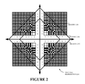
- FIG. 2 is a graphical view of a spectral distribution of low-pass, mid-band and high-pass coefficients in a rhombus pattern, according to one embodiment.
- FIG. 3 is a graphical view illustrating rhombus scanning of DCT coefficients, according to one embodiment.
- FIG. 4 is a process flow that illustrates dividing a portion of a digital image and then applying a flipped-kernel discrete cosine transform to improve the compression ratio in image coding, according to another embodiment.
- FIG. 1 is a system view of image compression using DCT based technique, according to one embodiment.
- sixteen by sixteen pixel block 104 is same as 16 ⁇ 16 pixel block 104 and eight by eight pixel block 106 A-D is same as 8 ⁇ 8 pixel block B 1 -B 4 106 A-D.
- FIG. 1 is a system view of image compression using DCT based technique, according to one embodiment.
- sixteen by sixteen pixel block 104 is same as 16 ⁇ 16 pixel block 104 and eight by eight pixel block 106 A-D is same as 8 ⁇ 8 pixel block B 1 -B 4 106 A-D.
- FIG. 1 is a system view of image compression using DCT based technique, according to one embodiment.
- sixteen by sixteen pixel block 104 is same as 16 ⁇ 16 pixel block 104 and eight by eight pixel block 106 A-D is same as 8 ⁇ 8 pixel block B 1 -B 4 106 A-D.
- FIG. 1 is a system view of image compression using DCT based technique
- FIG. 1 illustrates a source image 100 , a pixel block formator 102 , a 16 ⁇ 16 pixel block 104 , an 8 ⁇ 8 pixel block B 1 -B 4 106 A-D, a DCT module 108 , a flipped-kernel discrete cosine transform 110 , a quantizer 112 , an 8 ⁇ 8 quantization table 114 , a coefficient scanner 116 , a rhombus scan 118 , an entropy coder 120 and a compressed data stream 122 , according to one embodiment.
- a portion of the source image 100 is divided into the 16 ⁇ 16 pixel block 104 by the pixel block formator 102 .
- the source image 100 may be an raw input image.
- the source image 100 may be either a gray-scale image or a color image.
- the pixel block formator 102 divides the source image 100 into a portion of 16 ⁇ 16 pixel block 104 .
- the flipped-kernel discrete cosine transform 110 may be applied to the 8 ⁇ 8 pixel blocks B 1 -B 4106 A-D.
- the pixel block formator 102 is communicatively coupled to the DCT module 108 .
- the DCT module 108 applies a specified two-dimensional DCT to 110 to each of the 8 ⁇ 8 pixel blocks B 1 -B 4 106 A-D.
- the specified two-dimensional DCT is a flipped-kernel discrete cosine transform 110 .
- the DCT module 108 applies the flipped-kernel discrete cosine transform 110 to each of the 8 ⁇ 8 pixel blocks B 1 -B 4 106 A-D.
- the flipped-kernel discrete cosine transform 110 applied to the 8 ⁇ 8 pixel block B 1 106 A may be:
- I B 1 (i, j) is the (i,j)th element of an image represented by the sub-block B 1 .
- I B1 (i,j) represents the pixel intensity values for sub-block B 1 .
- the flipped-kernel discrete cosine transform 110 applied to the 8 ⁇ 8 pixel block B 2 106 B may be:
- I B 2 (i, j) is the (i,j)th element of an image represented by the sub-block B 2 .
- I B2 (i,j) represents the pixel intensity values for sub-block B 2 .
- the flipped-kernel discrete cosine transform 110 applied to the 8 ⁇ 8 pixel block B 3 106 C may be:
- I B 3 (i, j) is the (i,j)th element of an image represented by the sub-block B 3 .
- I B3 (i,j) represents the pixel intensity values for sub-block B 3 .
- the flipped-kernel discrete cosine transform 110 applied to the 8 ⁇ 8 pixel block B 4 106 D may be:
- I B 4 (i, j) is the (i,j)th element of an image represented by the sub-block B 4 .
- I B4 (i,j) represents the pixel intensity values for sub-block B 4 .
- a DCT coefficient matrix of a resulting 16 ⁇ 16 block is:
- X [ X B ⁇ ⁇ 1 X B ⁇ ⁇ 1 X B ⁇ ⁇ 3 X B ⁇ ⁇ 4 ]
- a spectral coefficient of the result of the application of the flipped-kernel discrete cosine transform 110 is shown in FIG. 2 .
- the spectral coefficient of the 8 ⁇ 8 pixel blocks B 1 -B 4 106 A-D are quantized with the 8 ⁇ 8 quantization table 114 .
- the quantizer 112 removes visually insignificant information from the 8 ⁇ 8 pixel blocks B 1 -B 4 106 A-D.
- the quantization process includes dividing each 8 ⁇ 8 pixel blocks B 1 -B 4 106 A-D component in the frequency domain by a constant. The result of the division of each of the 8 ⁇ 8 pixel blocks B 1 -B 4 106 A-D component in the frequency domain is rounded by a constant to a nearest value.
- the quantization process may be a lossy operation.
- quantization matrices used for the four 8 ⁇ 8 pixel blocks B 1 -B 4 106 A-D are given below, according to an example embodiment:
- the Q matrix includes the general quantization matrix used in the standard image coding:
- the B 1 specified quantization matrix of the 8 ⁇ 8 pixel block B 1 106 A includes:
- the B 2 specified quantization matrix of the 8 ⁇ 8 pixel block B 2 106 B includes:
- the B 3 specified quantization matrix of the 8 ⁇ 8 pixel block B 3 106 C includes:
- the coefficient scanner 116 applies a rhombus scan 118 to the DCT coefficients as quantized by the quantizer 112 .
- the quantized DCT coefficient of the 16 ⁇ 16 pixel block 104 is scanned using a coefficient scanner 116 .
- the scanning is applied in a rhombus fashion.
- the rhombus scan 118 groups the low-pass to high frequency coefficients of all the four 8 ⁇ 8 pixel blocks B 1 -B 4 106 A-D as output to the entropy coder 120 .
- the coefficient scanner 116 is coupled to the entropy coder 120 .
- the entropy coder 120 generates the compressed data stream 122 .
- the entropy coder 120 then processes this data to output the compressed data steam 122 .
- the entropy coder 120 may apply a lossless data compression scheme that is independent of the specific characteristics of the medium.
- the encoding technique may include Huffman coding and/or arithmetic coding, according particular example embodiments.
- the resulting compressed data stream 122 may be edge in run-length coding of zero magnitude coefficients. The zero magnitude coefficients may lead to higher compression with negligible or almost zero increase in computational complexity.
- FIG. 2 is a graphical view of a spectral distribution of low-pass, mid-band and high-pass coefficients in a rhombus pattern, according to another embodiment. Particularly, FIG. 2 illustrates the spectral distribution 200 , a region 1 202 , a region 2 204 , a region 3 206 , according to one embodiment.
- the region 1 202 signifies the low pass region
- the region 2 204 signifies the mid-band region
- the region 3 206 signifies the high-pass region.
- the low pass to high pass distribution of spectral coefficients within each 16 ⁇ 16 pixel block 104 are illustrated in FIG. 2 .
- the low pass distribution of spectral coefficients of an image is more sensitive to the human eye.
- the high pass distribution of spectral coefficients of an image is less sensitive to the human eye.
- FIG. 3 is a graphical view illustrating rhombus scanning of DCT coefficients, according to one embodiment. Particularly, FIG. 3 illustrates a rhombus scanning 300 and a 16 ⁇ 16 block DCT coefficient 302 , according to one embodiment.
- the 16 ⁇ 16 block DCT coefficients 302 are scanned by rhombus scan 300 .
- the quantized DCT coefficient of the 16 ⁇ 16 pixel block 104 is scanned with the coefficient scanner 116 .
- the rhombus scan 118 groups the low-pass to high frequency coefficients of the four 8 ⁇ 8 pixel blocks B 1 -B 4 106 A-D.
- the rhombus scanning 300 generates a long-run of zeros in the high pass region, after reordering.
- the high pass region is be the region 3 206 .
- the high correlation between the different sub-block, AC and DC coefficients may also be exploited for further improvement in compression ratio.
- the 2-dimensional array of quantized DCT coefficients X may be mapped to a linear array L.
- the linear array L may be of size 256.
- FIG. 4 is a process flow that illustrates dividing a portion of a digital image and then applying a flipped-kernel discrete cosine transform to improve the compression ratio in image coding, according to another embodiment.
- the portion of a digital image may be divided into a sixteen by sixteen pixel block 104 .
- a pixel-block formator 102 may be used to divide the portion of the digital image.
- the digital image may be the source image 100 .
- the flipped-kernel discrete cosine transform 110 may be applied to an eight by eight pixel sub-block 106 A-D of the sixteen by sixteen pixel block 104 .
- a DCT module 108 may be used to apply the flipped-kernel discrete cosine transform 110 .
- a visually insignificant information may be removed from the eight by eight pixel sub-block 106 A-D with a quantization method.
- the quantizer 112 may remove the visually insignificant information.
- a spectral coefficient of the eight by eight pixel sub-block 106 A-D may be quantized with an eight by eight pixel quantization table 114 .
- the eight by eight pixel sub-block 106 A-D component in a frequency domain may be divided by a constant.
- a result of the dividing an eight by eight pixel sub-block 106 A-D component in a frequency domain may be rounded by a constant to a nearest integer.
- the quantizer 112 may round the result.
- a quantized discrete cosine transform coefficient of the sixteen by sixteen pixel block 104 may be scanned according to a rhomboid pattern.
- the coefficient scanner 116 may scan the discrete cosine transform coefficient.
- the various devices, modules, analyzers, generators, etc. described herein may be enabled and operated using hardware circuitry, firmware, software or any combination of hardware, firmware, or software embodied in a machine readable medium.
- the various electrical structure and methods may be embodied using transistors, logic gates, application specific integrated (ASIC) circuitry or Digital Signal Processor (DSP) circuitry.
Abstract
Description
QB4=Q
Claims (20)
QB4=Q.
Priority Applications (1)
| Application Number | Priority Date | Filing Date | Title |
|---|---|---|---|
| US12/428,494 US8311354B2 (en) | 2009-04-23 | 2009-04-23 | DCT-based technique with rhombus scanning for image compression |
Applications Claiming Priority (1)
| Application Number | Priority Date | Filing Date | Title |
|---|---|---|---|
| US12/428,494 US8311354B2 (en) | 2009-04-23 | 2009-04-23 | DCT-based technique with rhombus scanning for image compression |
Publications (2)
| Publication Number | Publication Date |
|---|---|
| US20100272374A1 US20100272374A1 (en) | 2010-10-28 |
| US8311354B2 true US8311354B2 (en) | 2012-11-13 |
Family
ID=42992198
Family Applications (1)
| Application Number | Title | Priority Date | Filing Date |
|---|---|---|---|
| US12/428,494 Active 2031-06-18 US8311354B2 (en) | 2009-04-23 | 2009-04-23 | DCT-based technique with rhombus scanning for image compression |
Country Status (1)
| Country | Link |
|---|---|
| US (1) | US8311354B2 (en) |
Families Citing this family (2)
| Publication number | Priority date | Publication date | Assignee | Title |
|---|---|---|---|---|
| JP5741076B2 (en) | 2010-12-09 | 2015-07-01 | ソニー株式会社 | Image processing apparatus and image processing method |
| US10405000B2 (en) * | 2014-11-21 | 2019-09-03 | Vid Scale, Inc. | One-dimensional transform modes and coefficient scan order |
Citations (3)
| Publication number | Priority date | Publication date | Assignee | Title |
|---|---|---|---|---|
| JPH09224247A (en) * | 1996-02-16 | 1997-08-26 | Nec Corp | Device and method for compression-encoding image |
| US5751865A (en) * | 1996-09-26 | 1998-05-12 | Xerox Corporation | Method and apparatus for image rotation with reduced memory using JPEG compression |
| US20060209956A1 (en) * | 2005-03-21 | 2006-09-21 | Pixart Imaging Inc. | Motion estimation method utilizing modified rhombus pattern search for a succession of frames in digital coding system |
-
2009
- 2009-04-23 US US12/428,494 patent/US8311354B2/en active Active
Patent Citations (3)
| Publication number | Priority date | Publication date | Assignee | Title |
|---|---|---|---|---|
| JPH09224247A (en) * | 1996-02-16 | 1997-08-26 | Nec Corp | Device and method for compression-encoding image |
| US5751865A (en) * | 1996-09-26 | 1998-05-12 | Xerox Corporation | Method and apparatus for image rotation with reduced memory using JPEG compression |
| US20060209956A1 (en) * | 2005-03-21 | 2006-09-21 | Pixart Imaging Inc. | Motion estimation method utilizing modified rhombus pattern search for a succession of frames in digital coding system |
Also Published As
| Publication number | Publication date |
|---|---|
| US20100272374A1 (en) | 2010-10-28 |
Similar Documents
| Publication | Publication Date | Title |
|---|---|---|
| CN100576195C (en) | With the system and method for lossless manner to digital picture and voice data decoding | |
| JP2001298366A (en) | Method for compressing image data, and method and device for quantizing data | |
| RU2567988C2 (en) | Encoder, method of encoding data, decoder, method of decoding data, system for transmitting data, method of transmitting data and programme product | |
| US20220174329A1 (en) | Image encoding method and apparatus, image decoding method and apparatus, and chip | |
| EP1406447A1 (en) | Method and system for processing signals via perceptive vectorial quantization, computer program product therefor | |
| Arora et al. | A comprehensive review of image compression techniques | |
| CN101919252A (en) | Separate huffman coding of runlength and size data of DCT coefficients | |
| US20020191695A1 (en) | Interframe encoding method and apparatus | |
| CN105163130B (en) | A kind of Lossless Image Compression Algorithm method based on discrete Tchebichef orthogonal polynomial | |
| US8311354B2 (en) | DCT-based technique with rhombus scanning for image compression | |
| JP3163880B2 (en) | Image compression coding device | |
| Joshua et al. | Comparison of DCT and DWT image compression | |
| Rajakumar et al. | Implementation of Multiwavelet Transform coding for lossless image compression | |
| US6766341B1 (en) | Faster transforms using scaled terms | |
| Hussin et al. | A comparative study on improvement of image compression method using hybrid DCT-DWT techniques with huffman encoding for wireless sensor network application | |
| CN1822050A (en) | Full phase anticosine double orthogonal transformation and its improving method for JPEG | |
| US6633679B1 (en) | Visually lossless still image compression for CMYK, CMY and Postscript formats | |
| Al-Khafaji | Linear Polynomial Coding with Midtread Adaptive Quantizer | |
| Stamm | PGF: A new progressive file format for lossy and lossless image compression | |
| KR100349518B1 (en) | Image compressing method and device by using the discrete wavelet transform applied for fuzzy logics considering the human vision system | |
| JP2841197B2 (en) | Method of compressing gradation image data | |
| Abd-Elhafiez et al. | New efficient method for coding color images | |
| Hilles et al. | Image coding techniques in networking | |
| US7609902B2 (en) | Implementation of discrete cosine transformation and its inverse on programmable graphics processor | |
| Sultan | Image compression by using walsh and framelet transform |
Legal Events
| Date | Code | Title | Description |
|---|---|---|---|
| STCF | Information on status: patent grant |
Free format text: PATENTED CASE |
|
| AS | Assignment |
Owner name: DEUTSCHE BANK AG NEW YORK BRANCH, AS COLLATERAL AG Free format text: PATENT SECURITY AGREEMENT;ASSIGNORS:LSI CORPORATION;AGERE SYSTEMS LLC;REEL/FRAME:032856/0031 Effective date: 20140506 |
|
| FEPP | Fee payment procedure |
Free format text: PAYOR NUMBER ASSIGNED (ORIGINAL EVENT CODE: ASPN); ENTITY STATUS OF PATENT OWNER: LARGE ENTITY |
|
| AS | Assignment |
Owner name: INTEL CORPORATION, CALIFORNIA Free format text: ASSIGNMENT OF ASSIGNORS INTEREST;ASSIGNOR:LSI CORPORATION;REEL/FRAME:035090/0477 Effective date: 20141114 |
|
| AS | Assignment |
Owner name: LSI CORPORATION, CALIFORNIA Free format text: ASSIGNMENT OF ASSIGNORS INTEREST;ASSIGNORS:BALLAPALLE, PRABHAKAR;KUMAR, PHANI U.;REEL/FRAME:035233/0388 Effective date: 20090422 |
|
| AS | Assignment |
Owner name: LSI CORPORATION, CALIFORNIA Free format text: TERMINATION AND RELEASE OF SECURITY INTEREST IN PATENTS AT REEL/FRAME NO. 32856/0031;ASSIGNOR:DEUTSCHE BANK AG NEW YORK BRANCH;REEL/FRAME:035797/0943 Effective date: 20150420 |
|
| AS | Assignment |
Owner name: AGERE SYSTEMS LLC, PENNSYLVANIA Free format text: TERMINATION AND RELEASE OF SECURITY INTEREST IN PATENT RIGHTS (RELEASES RF 032856-0031);ASSIGNOR:DEUTSCHE BANK AG NEW YORK BRANCH, AS COLLATERAL AGENT;REEL/FRAME:037684/0039 Effective date: 20160201 Owner name: LSI CORPORATION, CALIFORNIA Free format text: TERMINATION AND RELEASE OF SECURITY INTEREST IN PATENT RIGHTS (RELEASES RF 032856-0031);ASSIGNOR:DEUTSCHE BANK AG NEW YORK BRANCH, AS COLLATERAL AGENT;REEL/FRAME:037684/0039 Effective date: 20160201 |
|
| FPAY | Fee payment |
Year of fee payment: 4 |
|
| MAFP | Maintenance fee payment |
Free format text: PAYMENT OF MAINTENANCE FEE, 8TH YEAR, LARGE ENTITY (ORIGINAL EVENT CODE: M1552); ENTITY STATUS OF PATENT OWNER: LARGE ENTITY Year of fee payment: 8 |