US8310081B2 - Power line communications coupler for effecting signal coupling between electric signaling equipment and an electric power system - Google Patents
Power line communications coupler for effecting signal coupling between electric signaling equipment and an electric power system Download PDFInfo
- Publication number
- US8310081B2 US8310081B2 US12/295,807 US29580707A US8310081B2 US 8310081 B2 US8310081 B2 US 8310081B2 US 29580707 A US29580707 A US 29580707A US 8310081 B2 US8310081 B2 US 8310081B2
- Authority
- US
- United States
- Prior art keywords
- coupler
- fuse
- electric
- power line
- power system
- Prior art date
- Legal status (The legal status is an assumption and is not a legal conclusion. Google has not performed a legal analysis and makes no representation as to the accuracy of the status listed.)
- Active, expires
Links
Images


Classifications
-
- H—ELECTRICITY
- H04—ELECTRIC COMMUNICATION TECHNIQUE
- H04B—TRANSMISSION
- H04B3/00—Line transmission systems
- H04B3/54—Systems for transmission via power distribution lines
- H04B3/56—Circuits for coupling, blocking, or by-passing of signals
-
- H—ELECTRICITY
- H04—ELECTRIC COMMUNICATION TECHNIQUE
- H04B—TRANSMISSION
- H04B2203/00—Indexing scheme relating to line transmission systems
- H04B2203/54—Aspects of powerline communications not already covered by H04B3/54 and its subgroups
- H04B2203/5462—Systems for power line communications
- H04B2203/5483—Systems for power line communications using coupling circuits
Definitions
- the present invention relates to a power line communications coupler.
- Power line communication involves sending electric data signals through electrically conductive power cables together with electric power signals.
- Networks for distributing electric power signals constitute the largest deployed networks in the world. Such networks can be used for electric data signal transmission. Numerous protocols have been developed into standards governing transmission of electric data signals through power lines. The coupling of these electric data signals to and from electrically conductive power cables safely and in compliance with government regulations while maintaining low signal loss is key to the successful deployment of these power line communications systems.
- U.S. Pat. No. 7,145,440 discloses a broadband coupler capable of direct electrical connection to an energised power line.
- the coupler includes a conductive portion movable by an adjustable member from a non-conducting retracted position spaced apart from the power transmission line to a forward conducting position in electrical contact with the power line.
- An insulated arm supports the coupler on the power line.
- a base on the coupler is engageable with a remotely activated tool in order to accomplish the electrical connection in a safe and secure manner.
- broadband data signals are sent to and from customer premises along the shared energized power lines.
- New coupler connections to the energized power lines allow the additional broadband customers and/or repeaters to join the communication system.
- couplers taught by U.S. Pat. No. 7,145,440 may provide connections to control electronics, routers, wireless transceivers, and may allow the broadband signals to bypass transformers on the power lines.
- a power line communications coupler for effecting signal coupling between electric signalling equipment and an electric power system, said coupler including a fuse coupleable to a power line of said electric power system; and a signal coupler in electrical communication with said fuse and being couplable to said signalling equipment.
- the fuse and the signal coupler are substantially arranged within a housing.
- the housing includes a host fuse holder.
- FIG. 1 is a circuit diagram of a preferred embodiment of the invention
- FIG. 2 is a diagrammatic illustration showing the components of the embodiment of the invention shown in FIG. 1 ;
- FIG. 3 is a schematic diagram showing electric signalling equipment in electrical communication with an electric power system by way of a power line communications coupler;
- FIG. 4 is a diagrammatic illustration of a perspective view of the power line communications coupler shown in FIG. 3 ;
- FIG. 5 is a diagrammatic illustration of another perspective view of the power line communications coupler shown in FIG. 3 ;
- FIG. 6 is a diagrammatic illustration of an exploded view of the power line communications coupler shown in FIG. 3 ;
- FIG. 7 is a circuit diagram of a signal coupler of the power line communications coupler shown in FIG. 3 ;
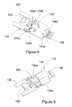
- FIG. 8 is a diagrammatic illustration of a perspective view of a top side of the signal coupler shown in FIG. 7 ;
- FIG. 9 is a diagrammatic illustration of a perspective view of a bottom side of the signal coupler shown in FIG. 7 ;
- FIG. 10 is a diagrammatic illustration of a bottom view of the signal coupler shown in FIG. 7 ;
- FIG. 11 is a diagrammatic illustration of a side view of the signal coupler shown in FIG. 7 ;
- FIG. 12 is a diagrammatic illustration of a top view of the signal coupler shown in FIG. 7 ;
- FIG. 13 is a diagrammatic illustration of a bottom view of a printed circuit board of the signal coupler shown in FIG. 7 ;
- FIG. 14 is a diagrammatic illustration of a side view of a printed circuit board of the signal coupler shown in FIG. 7 ;
- FIG. 15 is a diagrammatic illustration of a top view of a printed circuit board of the signal coupler shown in FIG. 7 .
- An embodiment of the invention 10 is a combined fuse holder and signal coupler between a signal system and an electrical power system as illustrated in FIG. 1 and FIG. 2 comprising:
- the power line communications coupler 100 shown in FIG. 4 functions in an analogous manner to that of the embodiment of the invention shown in FIGS. 1 and 2 . That is, the coupler 100 is used to effect signal coupling between electric signalling equipment 102 and an electric power system 104 .
- the power line communications coupler 100 is adapted to receive electric data signals from said signalling equipment 102 and send said electric data signals to one or more power line communication equipment end points of the electric power system 104 . Further, the power line communications coupler 100 is adapted to receive electric data signals from the signalling equipment 102 and send the electric data signals to one or more intermediate power line communication equipment repeater systems that form part of the electric power system 104 .
- the coupler 100 includes a fuse 106 coupleable to a power line 108 a , 108 b of the electric power system 104 .
- the coupler 100 also includes a signal coupler 110 in electrical communication with the fuse and couplable to the signalling equipment 102 .
- the coupler 100 includes a generally hollow cylindrical housing 112 that is formed in the following two intermatable parts:
- the fuse holder 114 is generally cylindrical and includes a right angle active phase contact 118 at a first end 117 .
- the right angled active phase contact 118 is used to electrically connect the coupler 100 to an insulation piercing probe (not shown) coupled to an active phase power line 108 a of the electric system 104 .
- the fuse holder 114 includes an in-line active phase contact (not shown) for electrically connecting to the insulation piercing probe (not shown) coupled to the active phase power line 108 a of the electric system 104 .
- An open end 119 of the cylindrical fuse holder 114 is shaped to receive, and securely seat therein, the fuse 106 .
- the coupler 100 includes an annular spacer 124 seated in the fuse holder 114 .
- the fuse 106 extends through the spacer 124 when seated in the fuse housing 114 .
- the spacer 124 preferably locates the fuse 106 in position for electrical connection to the signal coupler 110 and electrically isolates the fuse 106 from the internal peripheral walls of the housing 112 .
- the fuse 106 is preferably a high rupture current fuse.
- a first end 121 of the generally cylindrical coupling head 116 includes a socket 120 that is shaped to receive a screened mains rated signal cable (not shown). Another open end 122 of the coupling head 116 is shaped to receive, and securely seat therein, the signal coupler 110 (the operation of the signal coupler is described in further detail below).
- the open ends 117 , 122 of the fuse holder 114 and the coupler head 116 include interlocking parts.
- the open ends 117 , 122 are coupled together by way of respective snap lock male and female interlocking parts.
- the open ends 117 , 122 are be secured together by way of corresponding helical threads.
- the open ends 117 , 122 of the fuse holder 114 and the coupler head 116 can be coupled together by way of any other suitable means.
- the fuse 106 and the signal coupler 110 are substantially arranged within the housing 112 when the fuse holder 114 and the coupling head 116 are coupled together in the described manner.
- the signal coupler 110 includes a typical power line communications coupling circuit built on a potted printed circuit board 130 .
- the signal coupler 110 includes parallel isolation capacitors 132 a , 132 b and 134 a , 134 b on each phase 108 a , 108 b connecting across the primary winding 138 of the isolation/matching transformer 140 (preferably PE-68629).
- the capacitors 132 a and 132 b are preferably 10 nF and 1.5 nF.
- the capacitors 134 a and 134 b are preferably 4.7 nF and 1.5 nF.
- the capacitors of each pair are disposed on opposite sides of the printed circuit board 130 .
- the capacitors of each pair are not arranged in parallel on opposite sides of the board to reduce interference therebetween.
- the secondary winding 142 terminating at diodes 144 a , 144 b (preferably TVS 0603 30V). Only low voltage signals are transferred via the isolation transformer 140 and a screened signal cable 146 (rated for use in an electrical environment that could be a Belden 8762 single pair screened cable) to and from the electric signalling equipment 102 .
- the transformer 140 has been selected and laid out on a printed circuit board 130 to ensure good frequency coupling response and matching impedance between the electric power system 104 and the electric signalling system 102 .
- the integrated fuse holder 114 includes a guide tube (not shown) open at both ends to permit moisture to drain out freely and a sprung contact 150 for the high current rupturing fuse 106 .
- the fuse 106 is likely to be accepted by most electrical authorities globally.
- One end of the fuse 106 is in electrical contact, via the existing host fuse holder contact 118 , with active phase 108 a of the high current electric power system 104 .
- the other end of the fuse 106 feeds the parallel pair of isolation capacitors 132 a , 132 b via an integrated sprung contact 150 .
- the parallel capacitors 132 a , 132 b address high end and low end frequencies.
- the signal coupler 110 includes an integrated indicator light 152 to directly indicate when the physical coupling to the electric power system 104 is of a low impedance with a specific pull down resistor 154 b (100 KOhms) to ensure a contact but high impedance connection is not indicated as good.
- the integrated indicator light 152 may expire after approximately two years, or when the isolation capacitors 132 a , 132 b and 134 a , 134 b have eventually sustained sufficient damage from ongoing power spikes to no longer be effective conductors or isolation capacitors.
- the housing 112 includes an aperture 158 through which the indicator can be viewed.
- the fuse holder 114 is, for example, a standard heavy duty host fuse holder 114 that is by Cavanna and could be of model DPA likely be accepted by most electrical authorities globally.
- the fuse holder 114 preferably encapsulates the potted printed circuit board 130 holding all the circuitry described in this embodiment of the invention, the integrated fuse 106 and the indicator light 152 .
- the resistors 154 a , 154 b (68 KOhms, 100 KOhms), located near the integrated fuse holder 114 , the sprung contact 150 are able to generate sufficient heat to dry out contacts normally dried out by the normal high current use of the host fuse holder 114 and also ensuring a small wetting whetting current continually circulates though the high current fuse 106 , heavy duty fuse holder assembly and physical connections 108 a , 108 b to the electric power system 104 to stimulate low impedance contact through the chain of contacts for the power line signal.
- the signal coupler 110 also includes a fuse 160 (preferably MOV V300LA4) to protect the circuit from spikes.
- the fuse 160 is preferably a quick acting 125 Volt, 2 Amp fuse.
- FIGS. 13 to 15 The arrangement of the tracks of the printed circuit board 130 of the signal coupler 110 are shown in FIGS. 13 to 15 . Tracks are laid on both sides of the board 130 .
- the board 130 is of sufficient size for installation within the fuse holder 114 .
Abstract
Description
-
- a typical power line
communications coupling circuit 11 built on a potted Printed Circuit Board insert 12 comprising of anisolation capacitor phase primary winding 18 of an isolation/matchingtransformer 20 with thesecondary winding 22 terminating at a small impedance matchingcapacitor 24. Only low voltage signals are transferred via theisolation transformer 20 and a screened signal cable 26 (rated for use in an electrical environment that could be a Belden 8762 single pair screened cable) to and from thesignal equipment 28. Thecapacitor 24 andtransformer 20 have been selected and laid out on a printedcircuit board 12 to ensure good frequency coupling response and matching impedance between theelectrical system 30 and thesignal system 28; - an integrated
fuse holder 44 consisting of aguide tube 32 open at both ends to permit moisture to drain out freely and sprungcontact 34 for a high current rupturingfuse 36 likely to be accepted by most electrical authorities globally where one end of thefuse 36 is in contact via the existing hostfuse holder contact 38 withactive phase 16 a of the high currentelectrical system 30 and the other end feeds thefirst capacitor 14 a via an integratedsprung contact 34; - an integrated
indicator light 40 to directly indicate when the physical coupling to theelectrical system 30 is of a low impedance with a specific pull downresistor 42 b to ensure a contact but high impedance connection is not indicated as good; - an integrated
indicator light 40 to expire after approximately two years or when theisolation capacitors - a standard heavy duty
host fuse holder 44 that could be manufactured by Cavanna and could be of model DPA likely be accepted by most electrical authorities globally, encapsulating the Potted Printed Circuit Board insert 12 holding all the circuitry described in this specification, the integratedfuse 36 and theindicator light 40; - an integrated
resistor network 46 located near the integratedfuse holder 44 sprungcontact 34 able to generate sufficient heat to dry outcontacts 46 normally dried out by the normal high current use of thehost fuse holder 44 and also ensuring a small wetting current continually circulates though the highcurrent fuse 36, heavy dutyfuse holder assembly physical connections electrical system 30 to stimulate low impedance contact through the chain of contacts for the power line signal.
- a typical power line
-
- a. The
fuse holder 114; and - b. The coupling head 116.
- a. The
Claims (12)
Applications Claiming Priority (3)
| Application Number | Priority Date | Filing Date | Title |
|---|---|---|---|
| AU2006901735A AU2006901735A0 (en) | 2006-04-04 | Integrated fuse/powerline capacitive coupler | |
| AU2006901735 | 2006-04-04 | ||
| PCT/AU2007/000450 WO2007112507A1 (en) | 2006-04-04 | 2007-04-04 | Power line communications coupler |
Publications (2)
| Publication Number | Publication Date |
|---|---|
| US20100046642A1 US20100046642A1 (en) | 2010-02-25 |
| US8310081B2 true US8310081B2 (en) | 2012-11-13 |
Family
ID=38563001
Family Applications (1)
| Application Number | Title | Priority Date | Filing Date |
|---|---|---|---|
| US12/295,807 Active 2028-12-19 US8310081B2 (en) | 2006-04-04 | 2007-04-04 | Power line communications coupler for effecting signal coupling between electric signaling equipment and an electric power system |
Country Status (3)
| Country | Link |
|---|---|
| US (1) | US8310081B2 (en) |
| EP (1) | EP2005612A4 (en) |
| WO (1) | WO2007112507A1 (en) |
Cited By (3)
| Publication number | Priority date | Publication date | Assignee | Title |
|---|---|---|---|---|
| US20120188677A1 (en) * | 2010-02-09 | 2012-07-26 | Huawei Technologies Co., Ltd. | Dsl protection circuit |
| US10277277B2 (en) * | 2017-08-31 | 2019-04-30 | Aclara Technologies Llc | ULF/VLF power line communications coupler |
| CN110809840A (en) * | 2017-06-29 | 2020-02-18 | 3M创新有限公司 | Cable coupler with power indicator light |
Families Citing this family (2)
| Publication number | Priority date | Publication date | Assignee | Title |
|---|---|---|---|---|
| AU2008313348A1 (en) | 2007-09-04 | 2009-04-23 | Adc Gmbh | Coupling housing over broadband power line communication |
| GB201014782D0 (en) * | 2010-09-07 | 2010-10-20 | Fibrepoint Ltd | A modular optical data network and related system |
Citations (9)
| Publication number | Priority date | Publication date | Assignee | Title |
|---|---|---|---|---|
| WO1998033258A2 (en) | 1997-01-28 | 1998-07-30 | Northern Telecom Limited | Power line transmission |
| WO2000049726A1 (en) | 1999-02-19 | 2000-08-24 | Siemens Aktiengesellschaft | Circuit for capacitively coupling data communication equipment to a power line and a coupling unit with a coupling circuit |
| US6690283B2 (en) * | 2000-08-04 | 2004-02-10 | Sony Corporation | Protective device and communication device |
| US6844810B2 (en) | 2002-10-17 | 2005-01-18 | Ambient Corporation | Arrangement of a data coupler for power line communications |
| US20060244571A1 (en) * | 2005-04-29 | 2006-11-02 | Yaney David S | Power line coupling device and method of use |
| US20060262881A1 (en) * | 2005-05-20 | 2006-11-23 | Yehuda Cern | Power line communications interface and surge protector |
| US7145440B2 (en) | 2004-10-12 | 2006-12-05 | At&T Corp. | Broadband coupler technique for electrical connection to power lines |
| US20070116257A1 (en) * | 2005-10-11 | 2007-05-24 | Duran Christian S | Sealing current terminator for inhibiting oxidation and methods therefor |
| US20090019634A1 (en) * | 2006-03-17 | 2009-01-22 | Toivo Lipponen | Steam bath cabinet |
-
2007
- 2007-04-04 WO PCT/AU2007/000450 patent/WO2007112507A1/en active Application Filing
- 2007-04-04 US US12/295,807 patent/US8310081B2/en active Active
- 2007-04-04 EP EP07718697A patent/EP2005612A4/en not_active Withdrawn
Patent Citations (9)
| Publication number | Priority date | Publication date | Assignee | Title |
|---|---|---|---|---|
| WO1998033258A2 (en) | 1997-01-28 | 1998-07-30 | Northern Telecom Limited | Power line transmission |
| WO2000049726A1 (en) | 1999-02-19 | 2000-08-24 | Siemens Aktiengesellschaft | Circuit for capacitively coupling data communication equipment to a power line and a coupling unit with a coupling circuit |
| US6690283B2 (en) * | 2000-08-04 | 2004-02-10 | Sony Corporation | Protective device and communication device |
| US6844810B2 (en) | 2002-10-17 | 2005-01-18 | Ambient Corporation | Arrangement of a data coupler for power line communications |
| US7145440B2 (en) | 2004-10-12 | 2006-12-05 | At&T Corp. | Broadband coupler technique for electrical connection to power lines |
| US20060244571A1 (en) * | 2005-04-29 | 2006-11-02 | Yaney David S | Power line coupling device and method of use |
| US20060262881A1 (en) * | 2005-05-20 | 2006-11-23 | Yehuda Cern | Power line communications interface and surge protector |
| US20070116257A1 (en) * | 2005-10-11 | 2007-05-24 | Duran Christian S | Sealing current terminator for inhibiting oxidation and methods therefor |
| US20090019634A1 (en) * | 2006-03-17 | 2009-01-22 | Toivo Lipponen | Steam bath cabinet |
Cited By (4)
| Publication number | Priority date | Publication date | Assignee | Title |
|---|---|---|---|---|
| US20120188677A1 (en) * | 2010-02-09 | 2012-07-26 | Huawei Technologies Co., Ltd. | Dsl protection circuit |
| US8625246B2 (en) * | 2010-02-09 | 2014-01-07 | Huawei Technologies Co., Ltd. | DSL protection circuit |
| CN110809840A (en) * | 2017-06-29 | 2020-02-18 | 3M创新有限公司 | Cable coupler with power indicator light |
| US10277277B2 (en) * | 2017-08-31 | 2019-04-30 | Aclara Technologies Llc | ULF/VLF power line communications coupler |
Also Published As
| Publication number | Publication date |
|---|---|
| EP2005612A1 (en) | 2008-12-24 |
| EP2005612A4 (en) | 2009-07-01 |
| WO2007112507A1 (en) | 2007-10-11 |
| US20100046642A1 (en) | 2010-02-25 |
Similar Documents
| Publication | Publication Date | Title |
|---|---|---|
| US7176786B2 (en) | Method of isolating data in a power line communications network | |
| TWI325661B (en) | Separable electrical connector component having a voltage output branch and a direct access point | |
| US8310081B2 (en) | Power line communications coupler for effecting signal coupling between electric signaling equipment and an electric power system | |
| US6590493B1 (en) | System, device, and method for isolating signaling environments in a power line communication system | |
| WO2002101952A1 (en) | Coupling circuits for power line communications | |
| CA1095975A (en) | Grounding device | |
| EA006177B1 (en) | Inductive coupling of a data signal to a power transmission cable | |
| JP2009517898A (en) | System and method for power line communication associated with refrigerated containers | |
| CN110198586B (en) | Monitor, lamp control system and method for controlling lamp | |
| RU2269869C2 (en) | Method for transferring high-frequency signals along low-voltage networks and device for realization of said method | |
| US20020089441A1 (en) | Output protected energiser | |
| CN101938075B (en) | Automation appliance | |
| MXPA04008688A (en) | Telecommunications terminal module. | |
| EP1062739A1 (en) | Telecommunications signal coupler apparatus and method | |
| US6992599B2 (en) | Terminal adapter for connecting a terminal to a computer local area network capable of identifying any of several terminal types | |
| US6847298B2 (en) | Data transmission | |
| US9588138B2 (en) | Electric base, electric gateway, and electric gateway body | |
| US20040166736A1 (en) | Multi-fusable electrical receptacle | |
| JP2007174412A (en) | Power line carrier communication system and its master set | |
| CA2368408A1 (en) | Signal coupler | |
| US20140192909A1 (en) | Apparatus for diversity coupling power line signals into a three-conductor power supply network | |
| WO2000060701A1 (en) | Coupling apparatus and method | |
| KR200327573Y1 (en) | Apparatus for connecting signal line with power line for power line communication | |
| JP2002217796A (en) | Transmission method for high frequency with power line | |
| CN2138865Y (en) | Branching device |
Legal Events
| Date | Code | Title | Description |
|---|---|---|---|
| AS | Assignment |
Owner name: ADC GMBH,GERMANY Free format text: ASSIGNMENT OF ASSIGNORS INTEREST;ASSIGNORS:YELLAND, DONALD MALCOLM ROSS;ALLWOOD, BRENT DAVID;SIGNING DATES FROM 20081118 TO 20081130;REEL/FRAME:023513/0291 Owner name: ADC GMBH, GERMANY Free format text: ASSIGNMENT OF ASSIGNORS INTEREST;ASSIGNORS:YELLAND, DONALD MALCOLM ROSS;ALLWOOD, BRENT DAVID;SIGNING DATES FROM 20081118 TO 20081130;REEL/FRAME:023513/0291 |
|
| STCF | Information on status: patent grant |
Free format text: PATENTED CASE |
|
| CC | Certificate of correction | ||
| AS | Assignment |
Owner name: TYCO ELECTRONICS SERVICES GMBH, SWITZERLAND Free format text: ASSIGNMENT OF ASSIGNORS INTEREST;ASSIGNOR:ADC GMBH;REEL/FRAME:036064/0578 Effective date: 20150410 |
|
| AS | Assignment |
Owner name: COMMSCOPE EMEA LIMITED, IRELAND Free format text: ASSIGNMENT OF ASSIGNORS INTEREST;ASSIGNOR:TYCO ELECTRONICS SERVICES GMBH;REEL/FRAME:036956/0001 Effective date: 20150828 |
|
| AS | Assignment |
Owner name: COMMSCOPE TECHNOLOGIES LLC, NORTH CAROLINA Free format text: ASSIGNMENT OF ASSIGNORS INTEREST;ASSIGNOR:COMMSCOPE EMEA LIMITED;REEL/FRAME:037012/0001 Effective date: 20150828 |
|
| AS | Assignment |
Owner name: JPMORGAN CHASE BANK, N.A., AS COLLATERAL AGENT, ILLINOIS Free format text: PATENT SECURITY AGREEMENT (TERM);ASSIGNOR:COMMSCOPE TECHNOLOGIES LLC;REEL/FRAME:037513/0709 Effective date: 20151220 Owner name: JPMORGAN CHASE BANK, N.A., AS COLLATERAL AGENT, ILLINOIS Free format text: PATENT SECURITY AGREEMENT (ABL);ASSIGNOR:COMMSCOPE TECHNOLOGIES LLC;REEL/FRAME:037514/0196 Effective date: 20151220 Owner name: JPMORGAN CHASE BANK, N.A., AS COLLATERAL AGENT, IL Free format text: PATENT SECURITY AGREEMENT (ABL);ASSIGNOR:COMMSCOPE TECHNOLOGIES LLC;REEL/FRAME:037514/0196 Effective date: 20151220 Owner name: JPMORGAN CHASE BANK, N.A., AS COLLATERAL AGENT, IL Free format text: PATENT SECURITY AGREEMENT (TERM);ASSIGNOR:COMMSCOPE TECHNOLOGIES LLC;REEL/FRAME:037513/0709 Effective date: 20151220 |
|
| FPAY | Fee payment |
Year of fee payment: 4 |
|
| AS | Assignment |
Owner name: COMMSCOPE, INC. OF NORTH CAROLINA, NORTH CAROLINA Free format text: RELEASE BY SECURED PARTY;ASSIGNOR:JPMORGAN CHASE BANK, N.A.;REEL/FRAME:048840/0001 Effective date: 20190404 Owner name: ANDREW LLC, NORTH CAROLINA Free format text: RELEASE BY SECURED PARTY;ASSIGNOR:JPMORGAN CHASE BANK, N.A.;REEL/FRAME:048840/0001 Effective date: 20190404 Owner name: COMMSCOPE TECHNOLOGIES LLC, NORTH CAROLINA Free format text: RELEASE BY SECURED PARTY;ASSIGNOR:JPMORGAN CHASE BANK, N.A.;REEL/FRAME:048840/0001 Effective date: 20190404 Owner name: ALLEN TELECOM LLC, ILLINOIS Free format text: RELEASE BY SECURED PARTY;ASSIGNOR:JPMORGAN CHASE BANK, N.A.;REEL/FRAME:048840/0001 Effective date: 20190404 Owner name: REDWOOD SYSTEMS, INC., NORTH CAROLINA Free format text: RELEASE BY SECURED PARTY;ASSIGNOR:JPMORGAN CHASE BANK, N.A.;REEL/FRAME:048840/0001 Effective date: 20190404 Owner name: ALLEN TELECOM LLC, ILLINOIS Free format text: RELEASE BY SECURED PARTY;ASSIGNOR:JPMORGAN CHASE BANK, N.A.;REEL/FRAME:049260/0001 Effective date: 20190404 Owner name: REDWOOD SYSTEMS, INC., NORTH CAROLINA Free format text: RELEASE BY SECURED PARTY;ASSIGNOR:JPMORGAN CHASE BANK, N.A.;REEL/FRAME:049260/0001 Effective date: 20190404 Owner name: COMMSCOPE, INC. OF NORTH CAROLINA, NORTH CAROLINA Free format text: RELEASE BY SECURED PARTY;ASSIGNOR:JPMORGAN CHASE BANK, N.A.;REEL/FRAME:049260/0001 Effective date: 20190404 Owner name: ANDREW LLC, NORTH CAROLINA Free format text: RELEASE BY SECURED PARTY;ASSIGNOR:JPMORGAN CHASE BANK, N.A.;REEL/FRAME:049260/0001 Effective date: 20190404 Owner name: COMMSCOPE TECHNOLOGIES LLC, NORTH CAROLINA Free format text: RELEASE BY SECURED PARTY;ASSIGNOR:JPMORGAN CHASE BANK, N.A.;REEL/FRAME:049260/0001 Effective date: 20190404 |
|
| AS | Assignment |
Owner name: JPMORGAN CHASE BANK, N.A., NEW YORK Free format text: ABL SECURITY AGREEMENT;ASSIGNORS:COMMSCOPE, INC. OF NORTH CAROLINA;COMMSCOPE TECHNOLOGIES LLC;ARRIS ENTERPRISES LLC;AND OTHERS;REEL/FRAME:049892/0396 Effective date: 20190404 Owner name: JPMORGAN CHASE BANK, N.A., NEW YORK Free format text: TERM LOAN SECURITY AGREEMENT;ASSIGNORS:COMMSCOPE, INC. OF NORTH CAROLINA;COMMSCOPE TECHNOLOGIES LLC;ARRIS ENTERPRISES LLC;AND OTHERS;REEL/FRAME:049905/0504 Effective date: 20190404 Owner name: WILMINGTON TRUST, NATIONAL ASSOCIATION, AS COLLATE Free format text: PATENT SECURITY AGREEMENT;ASSIGNOR:COMMSCOPE TECHNOLOGIES LLC;REEL/FRAME:049892/0051 Effective date: 20190404 Owner name: WILMINGTON TRUST, NATIONAL ASSOCIATION, AS COLLATERAL AGENT, CONNECTICUT Free format text: PATENT SECURITY AGREEMENT;ASSIGNOR:COMMSCOPE TECHNOLOGIES LLC;REEL/FRAME:049892/0051 Effective date: 20190404 |
|
| MAFP | Maintenance fee payment |
Free format text: PAYMENT OF MAINTENANCE FEE, 8TH YEAR, LARGE ENTITY (ORIGINAL EVENT CODE: M1552); ENTITY STATUS OF PATENT OWNER: LARGE ENTITY Year of fee payment: 8 |
|
| AS | Assignment |
Owner name: WILMINGTON TRUST, DELAWARE Free format text: SECURITY INTEREST;ASSIGNORS:ARRIS SOLUTIONS, INC.;ARRIS ENTERPRISES LLC;COMMSCOPE TECHNOLOGIES LLC;AND OTHERS;REEL/FRAME:060752/0001 Effective date: 20211115 |