US8301408B2 - Temperature prediction transmitter - Google Patents
Temperature prediction transmitter Download PDFInfo
- Publication number
- US8301408B2 US8301408B2 US12/720,355 US72035510A US8301408B2 US 8301408 B2 US8301408 B2 US 8301408B2 US 72035510 A US72035510 A US 72035510A US 8301408 B2 US8301408 B2 US 8301408B2
- Authority
- US
- United States
- Prior art keywords
- estimate
- filtered1
- processor
- quality
- detect
- Prior art date
- Legal status (The legal status is an assumption and is not a legal conclusion. Google has not performed a legal analysis and makes no representation as to the accuracy of the status listed.)
- Active, expires
Links
Images


Classifications
-
- G—PHYSICS
- G06—COMPUTING; CALCULATING OR COUNTING
- G06F—ELECTRIC DIGITAL DATA PROCESSING
- G06F17/00—Digital computing or data processing equipment or methods, specially adapted for specific functions
-
- G—PHYSICS
- G01—MEASURING; TESTING
- G01K—MEASURING TEMPERATURE; MEASURING QUANTITY OF HEAT; THERMALLY-SENSITIVE ELEMENTS NOT OTHERWISE PROVIDED FOR
- G01K7/00—Measuring temperature based on the use of electric or magnetic elements directly sensitive to heat ; Power supply therefor, e.g. using thermoelectric elements
- G01K7/42—Circuits effecting compensation of thermal inertia; Circuits for predicting the stationary value of a temperature
-
- G—PHYSICS
- G01—MEASURING; TESTING
- G01D—MEASURING NOT SPECIALLY ADAPTED FOR A SPECIFIC VARIABLE; ARRANGEMENTS FOR MEASURING TWO OR MORE VARIABLES NOT COVERED IN A SINGLE OTHER SUBCLASS; TARIFF METERING APPARATUS; MEASURING OR TESTING NOT OTHERWISE PROVIDED FOR
- G01D3/00—Indicating or recording apparatus with provision for the special purposes referred to in the subgroups
- G01D3/028—Indicating or recording apparatus with provision for the special purposes referred to in the subgroups mitigating undesired influences, e.g. temperature, pressure
- G01D3/032—Indicating or recording apparatus with provision for the special purposes referred to in the subgroups mitigating undesired influences, e.g. temperature, pressure affecting incoming signal, e.g. by averaging; gating undesired signals
-
- G—PHYSICS
- G01—MEASURING; TESTING
- G01K—MEASURING TEMPERATURE; MEASURING QUANTITY OF HEAT; THERMALLY-SENSITIVE ELEMENTS NOT OTHERWISE PROVIDED FOR
- G01K1/00—Details of thermometers not specially adapted for particular types of thermometer
Definitions
- This invention relates to the estimation of a signal with a physical time delay, and more particularly to a system of reducing or compensating for the time delay caused by a physical impediment in a signal using an infinite impulse response (“IIR”) filter.
- IIR infinite impulse response
- a temperature sensor may be positioned in the fluid flow.
- the process fluid to be measured may be chemically incompatible with metallic temperature sensors, e.g., resulting in chemical attack or contamination of the solution and/or electrodes.
- the fluid may damage the temperature sensor, and build up of process fluid on the sensor may decrease the sensor's sensitivity.
- the fluid may also be part of a sanitary process, in which foreign objects such as sensors should not contact the process fluid.
- a conventional approach is to place the temperature sensor within a protective casing. With such a casing, the temperature sensor may be placed within the process fluid flow, while being protected from the process fluid by the casing. This approach relies on thermal conduction through the casing wall to the temperature sensor, to obtain temperature data.
- a drawback of this traditional solution is that the casing acts as a temperature insulator, thus impeding the sensor's ability to detect temperature change.
- casings for temperature detectors to be placed in conduits containing corrosive fluids are fabricated from polymers such as PFA (perfluoroalkoxy polymer resin), PTFE (polytetrafluoroethylene), polyvinyl chloride (PVC), or various combinations thereof, such as perfluoroalkoxy-polytetrafluoroethylene co-polymer.
- PFA perfluoroalkoxy polymer resin
- PTFE polytetrafluoroethylene
- PVC polyvinyl chloride
- Some techniques for compensating for the inaccuracy and delay of such temperature sensors involve the use of additional temperature sensors, including sensors positioned on the outside of the conduit for the process fluid flow.
- Differences between the signals captured from these multiple sensors may be used to help estimate or otherwise compensate for the time delay.
- These techniques may be impractical for many applications, such as those involving relatively complicated, expensive casings, such as those which may contain other devices in addition to sensors. It may thus be cost prohibitive to use multiples of these relatively expensive, complicated casings on the conduit.
- the temperature 23 detected by a conventional temperature sensor in a polymer casing is plotted relative to actual process fluid temperature 21 .
- the detected temperature 23 has a relatively flattened amplitude and fails to reach the highs and lows of the process temperature 21 .
- one attempt to overcome these drawbacks includes passing a signal 7 , generated by the temperature sensor 3 within casing 5 , through a conventional filter 9 .
- Conventional filter 9 is used to process the signal to reduce noise (e.g., electrical interference from electronic hardware), such as by using averaging techniques to filter out electronic noise and to output a conventionally estimated temperature 11 .
- this conventionally filtered signal 25 while it may tend to reduce signal noise, tends not to compensate for the time lag. Rather, the conventionally filtered signal 25 may be viewed as increasing the time lag.
- a system for predicting, in real time, a physical quality with an impediment to accurate measurement includes a sensor configured to detect a physical quality (Q detect ), wherein measurement of the physical quality is subject to an impediment.
- the system includes an infinite impulse response filter (IIR) configured to filter Q detect and to output a first filtered quality measurement (Q filtered1 ) in real time.
- IIR infinite impulse response filter
- a processor is configured to calculate the estimated quality Q estimate using Q detect and Q filtered1 .
- the physical quality is temperature of a process fluid, as detected by a resistive temperature detector (RTD), with the physical impediment being a thermally insulative protective casing.
- RTD resistive temperature detector
- a method for transforming raw physical quality data into an estimated measured quality includes obtaining raw data representing a physical quality (Q detect ), in which an impediment exists to the detection of the physical quality.
- the method also includes filtering Q detect through an IIR, so that the IIR outputs Q filtered1 ; and calculating, the a processor in real time, the estimated measured quality (Q estimate ) using Q filtered1 and Q detect .
- multiple IIR filters may be used to enhance output accuracy.
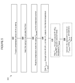
- FIG. 1A is a chart of a model of prior art temperature detection of process fluid flowing through a conduit
- FIG. 1B is a block diagram of prior art
- FIG. 1C is a chart of a model based on the prior art of FIG. 1B ;
- FIG. 2A is a block diagram of a system associated with an embodiment of the present invention.
- FIG. 2B is a block diagram of a system associated with an embodiment of the present invention.
- FIG. 3A is a block diagram of a system associated with an embodiment of the present invention.
- FIG. 3B is a block diagram of a system associated with an embodiment of the present invention.
- FIG. 4 is a flowchart of a method associated with an embodiment of the invention.
- FIG. 5 is a flowchart of a method associated with an embodiment of the invention.
- FIG. 6 is a flowchart of a method associated with an embodiment of the invention.
- FIG. 7 is a block diagram of a system associated with an embodiment of the present invention.
- FIG. 8 is a chart of a computer modeled results associated with an embodiment of the invention.
- FIG. 9 is a chart of a computer modeled results associated with another embodiment of the invention.
- an otherwise conventional infinite impulse response (IIR) filter may be configured to mimic, in real time, a physical system in which a physical impediment (e.g., a time-related impediment) is responsible for unwanted time delays in a sensor's detection of a physical property.
- a physical impediment e.g., a time-related impediment
- the inventor discovered that such an IIR filter may be configured to mimic the effects that the aforementioned RTD (or thermister or thermocouple, etc.) casing would generate in delaying the process temperature from reaching the sensor.
- the inventor hypothesized that programming an IIR with a time constant correlated to that of the physical impediment would mimic this physical impediment.
- this specially configured IIR filter may be used to effectively predict the temperature that would ultimately reach the RTD, to thus substantially eliminate the time delay to provide enhanced, i.e., nearly instantaneous, real time temperature detection.
- a second infinite impulse filter may be used in conjunction with the first filter, with the difference between the two filters being used to make further corrections.
- the second filter may be a substantial duplicate of the first filter, but which in particular embodiments uses a time constant that may be greater than that used in the first filter. (The time constants used may vary depending on the particular material e.g., casing, through which the temperature must propagate.)
- the filters are similar to conventional RC circuits in which some part of a new measurement and some part of the previous reading are mixed together linearly (e.g., some fraction of the new measurement and the complementary fraction of the last reading).
- the response is thus similar to the exponential response of an RC electrical circuit, to effectively provide an exponential, or ‘infinite’ response, from a single sensor.
- An aspect of the invention is thus the realization that the response coming through the casing to the temperature sensor from a change in the measured temperature may be modeled substantially accurately using this single or double-filtering approach. With the correct time constants, these embodiments enable one to effectively see how much of the remaining (exponential) heat transfer hasn't yet arrived, and then optionally filter again with a longer time constant so the difference is effectively corrected.
- real time refers to operations effected nearly simultaneously with actual events, such as to provide results which are delayed nominally only by the execution speed of the processor(s) used.
- an embodiment of the invention shown as system 100 includes sensor 14 , having a physical constraint (impediment) 12 .
- Sensor 14 is configured to detect a physical quality, Q detected 16 .
- An IIR filter, IIR 1 18 is configured to filter Q detected 16 using a constant k 1 , and to output first filtered reading Q filtered1 20 .
- Constant ⁇ 1 is predetermined to correlate to the known physical impediment 12 .
- Processor 26 is configured to accept inputs Q detected 16 and Q filtered1 20 , and to use these two inputs to produce Q estimate 28 , e.g., using Equation 1 below.
- Q estimate 2 ⁇ Q detected ⁇ Q filtered1 Eq. 1
- a single IIR filter may be used as shown, it should be recognized that additional IIR filters may be used, to provide enhanced results in many applications, as will be discussed below.
- quality Q may be temperature and constant ⁇ may be a time constant which correlates to a time delay associated with a barrier that is a relatively poor thermal conductor, as discussed below with respect to FIG. 2B .
- This embodiment may be particularly useful with temperature sensors used in a corrosive process fluid.
- a resistance temperature detector (“RTD”) may be encased in polypropylene and inserted into relatively corrosive chemical process fluids. While the polypropylene may protect the RTD from the process fluid, it has relatively low thermal conductivity, and therefore a relatively large time constant (delay), e.g., which may be measured in minutes rather than seconds.
- sensor 14 is a temperature sensor 14 , within a protective casing 12 , wherein the temperature sensor 14 is configured to detect T detected 16 , which is the temperature inside the casing 12 .
- the IIR filter, IIR 1 18 is configured to filter T detected 16 using a time constant ⁇ 1 , and to output first filtered temperature reading T filtered1 20 .
- Time constant ⁇ 1 is set to approximately one half of the known time delay caused by the relatively low thermal conductivity of the casing 12 .
- processor 26 is configured to accept inputs T detected 16 and T filtered1 20 , and to use these two inputs to produce T estimate 28 .
- Such a multiple-filter system is shown at 200 in FIG. 3A , and is substantially similar to system 100 , but for the addition of a second IIR filter, IIR 2 22 configured to receive and process Q filtered1 20 , and to output Q filtered2 24 .
- IIR 2 22 is thus configured to re filter Q filtered1 20 to provide a second input, Q filtered2 24 , for processor 26 .
- the first and second IIRs are each programmed with time constants correlated to the physical impediment 12 delaying the detection by sensor 14 .
- the time constant ( ⁇ 2 ) of the second IIR filter may be configured to be greater than or substantially equal to time constant ( ⁇ 1 ) of the first IIR filter.
- both IIRs were programmed with time constants of approximately one half that of the physical impediment 12 .
- Processor 26 is thus configured to receive both Q filtered1 20 , from IIR 1 18 , and Q filtered2 24 , from IIR 2 22 . Processor 26 is also configured to process these inputs to produce estimated temperature, Q estimate 28 . In particular embodiments, for example, the processor may be configured to calculate Q estimate 28 by the following Equation 2, i.e., by subtracting the value of Q filtered2 24 from twice the value of Q filtered1 20 , or by Equation 3, both of which have been found to yield similar results in many applications.
- Q estimate (2 ⁇ Q filtered1 ) ⁇ Q filtered2 Eq. 2
- Q estimate Q filtered2 +( Q filtered2 ⁇ Q filtered1 ) Eq. 3
- IIR 3 22 ′ additional IIRs may be added, such as shown in phantom in FIG. 3A as IIR 3 22 ′. Such additional IIRs may be disposed in series or in parallel with any of the other IIRs. These additional IIRs may be used to either further refine an estimated quality, or to model another physical impediment that may be present within the system such as in the event an RTD casing is placed within another casing.
- an additional IIR 22 ′ may be placed in parallel with IIR 22 , with both receiving either Q detected or Q filtered1 , to then feed their outputs Q filtered2 and Q filteredadd , respectively, to processor 26 .
- the processor 26 may then use the following Equation 4 to calculate Qestimate:
- Q estimate Q filtered1 +( Q filtered1 ⁇ Q filtered2 )+( Q filtered1 +Q filteredadd ) Eq. 4
- any of the embodiments disclosed herein may be configured in which the physical quantity to be measured is temperature.
- a system is shown at 202 in FIG. 3B , which is substantially similar to system 200 ( FIG. 3A ), in which sensor 14 is a temperature sensor, the physical impediment is the relatively poor thermal conductivity of a casing 12 , and the time constants of the IIR filters IIR 1 18 , and IIR 2 22 are correlated to the time constant of the casing.
- the second IIR filter, IIR 2 22 is configured to receive and re-filter T filtered1 20 , to output T filtered2 24 .
- Processor 26 is configured to receive both T filtered1 20 , from IIR 1 18 , and T filtered2 24 , from IIR 2 22 , and to generate estimated temperature, T estimate 28 .
- a raw signal from a single temperature sensor is processed in series through both the first and second IIR filters, creating an “in series” output, and is also processed separately through the first IIR filter, creating a “first filter” output.
- the “in series” output and the “first filter” output may be combined to determine the estimated temperature.
- the time constants are matched to the casing material, e.g., they are set to one-half that of the casing in particular embodiments.
- the time constant for a particular casing may be discovered empirically, e.g., by sending process fluid of a known temperature through a conduit, and measuring the time required for a temperature sensor in the casing to reach the known fluid temperature.
- the various embodiments of the subject invention may provide improved speed and accuracy, relative to conventional approaches by modeling the expected delay to effectively predict where the measured quality (e.g., temperature) will settle. Moreover, any of these embodiments may be further configured to use Equation 5, discussed hereinbelow, to further reduce the time delay for enhanced, nominally real time output.
- Embodiments of the claimed invention also involve methods for predicting a physical quality in applications involving a time-related impediment, such as predicting the temperature of a process fluid using a temperature sensor disposed within a casing. For convenience, these methods will be shown and described with respect to temperature measured by a sensor disposed within an insulative casing or with any other barrier disposed between the sensor and the substance being measured. It should be recognized, however, that any one or more of the embodiments shown and described herein may be used to analyze substantially any quality for which speed of detection may be hindered by some physical impediment.
- Some non-exclusive examples of such qualities may include temperature, pressure, flow, density, concentration, pH, ORP, index of refraction, turbidity, weight, mass, luminosity, position, etc. Moreover, it should be recognized that these qualities may be measured with substantially any type of sensor, including electronic, mechanical, electro-mechanical, chemical, and/or electro-chemical sensors, etc.
- a method for transforming raw sensor data representing a physical quality having a physical time constant (delay), into an estimated or predicted value is shown as method 300 .
- This method includes 302 , obtaining raw data representing temperature (T detected ) inside a casing within process fluid flow; 304 , filtering T detected through a first IIR (IIR 1 ), so that IIR 1 outputs T filtered1 ; 306 , optionally filtering T filtered1 through a second IIR (IIR 2 ), so that IIR 2 outputs T filtered2 and 308 , calculating the estimated temperature (T estimate ) using T filtered1 and optionally, T filtered2 .
- This method may also be used with more than two IIR filters, such as shown optionally at 310 .
- a method 400 for modeling an estimated temperature of a process fluid flow.
- This method includes 402 , encasing a temperature sensor within a casing; 404 , inserting the casing in the process fluid flow; 406 , reading the temperature inside the casing (T detected ) via the temperature sensor; 408 , filtering T detected through a first IIR (IIR 1 ), so that IIR 1 outputs a first filtered temperature (T filtered 1 ).
- Method 400 optionally includes 410 , filtering T filtered1 through a second IIR (IIR 2 ), so that IIR 2 outputs a second filtered temperature (T filtered2 ).
- the estimated temperature (T estimate ) is calculated using T filtered1 and optionally, T filtered2 .
- Method 500 of FIG. 6 is a method for estimating the temperature of a process fluid flow.
- This method includes 502 , detecting the temperature inside a casing (T detected ), the casing being inserted in a process fluid flow of a conduit; and 504 , processing T detected using a temperature estimation transmitter 506 ( FIG. 7 ).
- transmitter 506 may be an otherwise conventional process variable transmitter such as commercially available from Invensys Systems, Inc. (Foxboro, Mass.), which includes the aforementioned IIR 1 18 , processor 26 , and optionally, IIR 2 22 , as shown in phantom.
- FIG. 8 the inventor tested embodiments of their invention such as shown and described with respect to FIGS. 3A-3B , with computer modeling of a hypothetical process fluid. Temperature in degrees Celsius (y axis) is represented as a function of time in seconds (x axis). The actual process temperature 30 is represented by the solid line.
- the chart represents process fluid at 100° C. (e.g., boiling water) being sent through a conduit, followed by process fluid of 0° C. (e.g., ice water) at approximately 71 seconds.
- the process temperature line 30 thereby follows a step form.
- the chart also represents a gradual raising and lowering of the temperature of the process fluid, so that process temperature line 30 forms a sine wave.
- T estimate 28 more closely tracks the solid process line 30 .
- T estimate 28 slightly lags the process 30 , T estimate 28 comes close to the amplitude of the actual process temperature.
- the chart indicates that T estimate 28 reached 100° C. at about 50 seconds, and fell to about 15° C. at about 95 seconds. Since the process fluid 30 was rising in temperature at 95 seconds, T estimate 28 did not fall in temperature to the low of 0° Celsius.
- This computer model also allowed the inventor to compare T estimate 28 to the temperature (T detected ) 16 detected by the temperature sensor, (represented in this FIG. 8 by dashed line 32 ). It may be seen that than T estimate 28 is appreciably better than T detected line 32 at capturing the full amplitude (high and low amplitude) of temperature swings of process 30 .
- any of the foregoing embodiments may use another aspect of predicting the process temperature, which involves the slope of the changes in temperature detected by the sensor.
- the inventor experimented with simulations of process fluid in a conduit, with the process flow flowing past the casing.
- the slope of the sensor line 32 is proportional to the difference between the sensor temperature readings, and the actual process temperature.
- Equation 5 may be used to further enhance the estimated result, in which slope (Q estimatefinal ) estimate 34 is determined by multiplying the slope of the sensor output (Q detected ) line 32 by a predetermined constant K, and adding the result to the sensor line 32 .
- Q estimatefinal (Slope Q detected ⁇ K )+( Q detected ) Eq. 5
- the slope estimate 34 closely tracks the actual process fluid temperature 30 , nominally without any delay, to effectively compensate for the physical impediment (e.g., time delay caused by an RTD casing, etc.) to provide nominally true, real time results. This embodiment thus effectively anticipates what temperature the sensor will detect before the temperature is actually detected. As also shown, nominally the full amplitude of the process fluid temperature is captured.
- constant K the value used for the constant K was 40. It should be recognized, however, that constant K is related to the thermal time constant ⁇ discussed above. As such, the value of constant K is expected to change based on the particular application, and may be determined by empirical testing as discussed hereinabove.
- slope estimate 34 rather than forming a clear line, appears to be somewhat scattered around the process temperature 30 . This may reflect noise which has become part of the slope estimate. Therefore, processor 26 may be further programmed with a conventional smoothing algorithm, e.g., which averages or uses standard deviations of the data to smooth out the estimate 34 for enhanced clarity.
- a conventional smoothing algorithm e.g., which averages or uses standard deviations of the data to smooth out the estimate 34 for enhanced clarity.
- an electronic sensor 14 such as an RTD. It should be recognized, however, that substantially any type of sensor, including mechanical (e.g., pneumatic), electro-mechanical, and/or electro-chemical sensors / control systems, may be used without departing from the scope of the present invention.
Abstract
Description
Q estimate=2×Q detected −Q filtered1 Eq. 1
Although a single IIR filter may be used as shown, it should be recognized that additional IIR filters may be used, to provide enhanced results in many applications, as will be discussed below.
Q estimate=(2×Q filtered1)−Q filtered2 Eq. 2
Q estimate =Q filtered2+(Q filtered2 −Q filtered1) Eq. 3
Q estimate =Q filtered1+(Q filtered1 −Q filtered2)+(Q filtered1 +Q filteredadd) Eq. 4
Q estimatefinal=(SlopeQ detected ×K)+(Q detected) Eq. 5
As can be seen from the embodiment of
Claims (43)
Priority Applications (5)
| Application Number | Priority Date | Filing Date | Title |
|---|---|---|---|
| US12/720,355 US8301408B2 (en) | 2010-03-09 | 2010-03-09 | Temperature prediction transmitter |
| CN201180004050.1A CN102549385B (en) | 2010-03-09 | 2011-01-27 | Temperature prediction transmitter |
| EP11753746.4A EP2545341B1 (en) | 2010-03-09 | 2011-01-27 | Temperature prediction transmitter |
| PCT/US2011/022746 WO2011112288A1 (en) | 2010-03-09 | 2011-01-27 | Temperature prediction transmitter |
| US13/567,365 US8594968B2 (en) | 2010-03-09 | 2012-08-06 | Temperature prediction transmitter |
Applications Claiming Priority (1)
| Application Number | Priority Date | Filing Date | Title |
|---|---|---|---|
| US12/720,355 US8301408B2 (en) | 2010-03-09 | 2010-03-09 | Temperature prediction transmitter |
Related Child Applications (1)
| Application Number | Title | Priority Date | Filing Date |
|---|---|---|---|
| US13/567,365 Continuation US8594968B2 (en) | 2010-03-09 | 2012-08-06 | Temperature prediction transmitter |
Publications (2)
| Publication Number | Publication Date |
|---|---|
| US20110224940A1 US20110224940A1 (en) | 2011-09-15 |
| US8301408B2 true US8301408B2 (en) | 2012-10-30 |
Family
ID=44560768
Family Applications (2)
| Application Number | Title | Priority Date | Filing Date |
|---|---|---|---|
| US12/720,355 Active 2031-01-06 US8301408B2 (en) | 2010-03-09 | 2010-03-09 | Temperature prediction transmitter |
| US13/567,365 Active US8594968B2 (en) | 2010-03-09 | 2012-08-06 | Temperature prediction transmitter |
Family Applications After (1)
| Application Number | Title | Priority Date | Filing Date |
|---|---|---|---|
| US13/567,365 Active US8594968B2 (en) | 2010-03-09 | 2012-08-06 | Temperature prediction transmitter |
Country Status (4)
| Country | Link |
|---|---|
| US (2) | US8301408B2 (en) |
| EP (1) | EP2545341B1 (en) |
| CN (1) | CN102549385B (en) |
| WO (1) | WO2011112288A1 (en) |
Cited By (5)
| Publication number | Priority date | Publication date | Assignee | Title |
|---|---|---|---|---|
| US8594968B2 (en) | 2010-03-09 | 2013-11-26 | Invensys Systems, Inc. | Temperature prediction transmitter |
| DE102016104922A1 (en) | 2016-03-16 | 2017-10-12 | Endress+Hauser Conducta Gmbh+Co. Kg | Method for predicting a measured value and conductivity sensor for carrying out the method |
| US20180238741A1 (en) * | 2017-02-21 | 2018-08-23 | Rosemount Inc. | Process transmitter isolation compensation |
| US11226255B2 (en) | 2016-09-29 | 2022-01-18 | Rosemount Inc. | Process transmitter isolation unit compensation |
| US11226242B2 (en) | 2016-01-25 | 2022-01-18 | Rosemount Inc. | Process transmitter isolation compensation |
Families Citing this family (7)
| Publication number | Priority date | Publication date | Assignee | Title |
|---|---|---|---|---|
| DE102011089808A1 (en) * | 2011-12-23 | 2013-06-27 | Endress + Hauser Flowtec Ag | Method or measuring system for determining a density of a fluid |
| US9404812B2 (en) | 2013-03-14 | 2016-08-02 | Samsung Electronics Co., Ltd. | Method for detecting environmental value in electronic device and electronic device |
| CN104914800A (en) * | 2014-03-12 | 2015-09-16 | 株洲南车时代电气股份有限公司 | Inert data filtering method |
| JP6123741B2 (en) * | 2014-06-20 | 2017-05-10 | トヨタ自動車株式会社 | Cooler |
| US10274971B2 (en) | 2015-05-12 | 2019-04-30 | Moen Incorporated | Systems and methods of temperature control of downstream fluids using predictive algorithms |
| US11592200B2 (en) * | 2019-07-23 | 2023-02-28 | Schneider Electric USA, Inc. | Detecting diagnostic events in a thermal system |
| TWI824487B (en) * | 2022-04-15 | 2023-12-01 | 中國鋼鐵股份有限公司 | Tmeperature control decision guidance method and system |
Citations (33)
| Publication number | Priority date | Publication date | Assignee | Title |
|---|---|---|---|---|
| US3417617A (en) | 1965-12-13 | 1968-12-24 | Rall Dieter | Fluid stream temperature sensor system |
| US3487213A (en) | 1966-02-24 | 1969-12-30 | Rca Corp | Circuits for thermistor bolometer with increased responsivity |
| US3493949A (en) | 1966-04-11 | 1970-02-03 | Continental Sensing Inc | Methods of and apparatus for measuring and/or locating temperature conditions |
| US3759083A (en) | 1972-04-19 | 1973-09-18 | Atomic Energy Commission | Sensing element response time measuring system |
| US3878724A (en) | 1972-11-16 | 1975-04-22 | Gerald F Allen | Physically realizable optimum predictor filter technique for transducers, sensors, and other massive devices, based upon inverse transfers function synthesis |
| US3892281A (en) | 1974-07-31 | 1975-07-01 | Us Navy | Temperature measuring system having sensor time constant compensation |
| US3969943A (en) | 1974-03-06 | 1976-07-20 | Nippon Steel Corporation | Method of measuring the temperature of furnace hot stock and apparatus therefor |
| US3972237A (en) | 1974-05-28 | 1976-08-03 | American Medical Electronics Corporation | Electronic thermometer |
| US4092863A (en) | 1977-01-12 | 1978-06-06 | Johnson & Johnson | Electronic thermometer circuit |
| US4140999A (en) | 1976-05-03 | 1979-02-20 | Robertshaw Controls Company | Transformer hot spot detection system |
| US4178798A (en) | 1977-12-22 | 1979-12-18 | Robert Bosch Gmbh | Method and apparatus for measuring fuel consumption in internal combustion engines |
| US4221125A (en) | 1979-03-09 | 1980-09-09 | Emhart Industries, Inc. | Apparatus and method for detecting the presence of a substance on a liquid surface |
| US4232682A (en) | 1978-08-21 | 1980-11-11 | United States Surgical Corporation | Physiological parameter measuring system |
| US4380155A (en) | 1979-08-20 | 1983-04-19 | Whirlpool Corporation | Temperature sensing circuit with high noise immunity |
| US4470710A (en) | 1980-12-11 | 1984-09-11 | Commonwealth Of Australia | I. R. Radiation pyrometer |
| US4537067A (en) | 1982-11-18 | 1985-08-27 | Wilson Industries, Inc. | Inertial borehole survey system |
| US4556329A (en) | 1982-12-01 | 1985-12-03 | General Electric Company | Resistor temperature device trip unit |
| US4562554A (en) | 1983-06-09 | 1985-12-31 | The United States Of America As Represented By The Secretary Of The Navy | Universal microcomputer for individual sensors |
| US4605314A (en) | 1983-01-13 | 1986-08-12 | Lars Stenmark | Spectral discrimination pyrometer |
| US4815323A (en) | 1985-06-28 | 1989-03-28 | Simmonds Precision Products, Inc. | Ultrasonic fuel quantity gauging system |
| US20040023559A1 (en) | 2002-08-01 | 2004-02-05 | Jerry Wu | Electrical adapter |
| US20040024559A1 (en) | 2002-08-01 | 2004-02-05 | Down John Harry | Method, system and computer product for building calibration lookup tables from sparse data |
| US20040192196A1 (en) | 2003-03-27 | 2004-09-30 | In-Kyung Kim | Method and apparatus for establishing a clear sky reference value |
| US20050145273A1 (en) | 1997-03-28 | 2005-07-07 | Atwood John G. | Thermal cycler for PCR |
| US20060156830A1 (en) | 2002-12-06 | 2006-07-20 | Endress + Hauser Flowtec Ag | Process meter |
| US20060209921A1 (en) | 2005-03-16 | 2006-09-21 | Ford Global Technologies, Llc | A method of determining ambient air temperature |
| US20070008200A1 (en) | 2005-07-07 | 2007-01-11 | Hong-Yean Hsieh | Background calibration of continuous-time delta-sigma modulator |
| US20070027639A1 (en) * | 2002-03-29 | 2007-02-01 | Invensys Systems, Inc. | Startup Techniques for a Digital Flowmeter |
| US20070069931A1 (en) | 2005-09-23 | 2007-03-29 | Hong-Yean Hsieh | Self-calibrating continuous-time delta-sigma modulator |
| US20070200193A1 (en) | 2006-01-20 | 2007-08-30 | Infineon Technologies Ag | Component arrangement and method for determining the temperature in a semiconductor component |
| US20070252633A1 (en) | 2005-09-22 | 2007-11-01 | Frankel Jay I | Rate-based sensors for advanced real-time analysis and diagnostics |
| US20080025369A1 (en) | 2004-05-04 | 2008-01-31 | Texas Instruments Incorporated | Simultaneous control of deposition time and temperature of multi-zone furnaces |
| US20090277271A1 (en) | 2005-07-08 | 2009-11-12 | Valtion Teknillinen Tutkimuskeskus | Micromechanical Sensor, Sensor Array and Method |
Family Cites Families (52)
| Publication number | Priority date | Publication date | Assignee | Title |
|---|---|---|---|---|
| US4858155A (en) * | 1985-12-24 | 1989-08-15 | Beckman Instruments, Inc. | Reaction temperature control system |
| JPH0672306B2 (en) * | 1987-04-27 | 1994-09-14 | 株式会社半導体エネルギー研究所 | Plasma processing apparatus and plasma processing method |
| US4842417A (en) * | 1987-07-01 | 1989-06-27 | Norsk Hydro A.S. | Method and apparatus for indirectly measuring a solid-liquid interface equilibrium temperature |
| US4993419A (en) * | 1988-12-06 | 1991-02-19 | Exergen Corporation | Radiation detector suitable for tympanic temperature measurement |
| US5140609A (en) * | 1990-10-18 | 1992-08-18 | Rosemount Inc. | Trd temperature sensor |
| DE4034115C1 (en) * | 1990-10-26 | 1992-04-02 | Bayer Ag, 5090 Leverkusen, De | |
| US5517015A (en) * | 1990-11-19 | 1996-05-14 | Dallas Semiconductor Corporation | Communication module |
| DE69126885T3 (en) * | 1990-12-12 | 2001-10-18 | Sherwood Serv Ag | CALIBRATION OF AN INFRARED THERMOMETER BY MEANS OF AREA CALIBRATION DISPLAY |
| WO1993018494A1 (en) * | 1992-03-11 | 1993-09-16 | The Boeing Company | Thermal condition sensor system for monitoring equipment operation |
| DE4216082C2 (en) * | 1992-05-15 | 2000-01-20 | Stn Atlas Elektronik Gmbh | Method and device for correcting speed measurements |
| US5655403A (en) * | 1992-07-01 | 1997-08-12 | Whessoe Varec, Inc. | Reversible float for use in a tank gauging system |
| US5484206A (en) * | 1993-12-28 | 1996-01-16 | Houldsworth; John | Method and apparatus for sensing a cold junction temperature |
| FI96066C (en) * | 1994-03-24 | 1996-04-25 | Polar Electro Oy | Method and apparatus for determining the internal temperature and coefficient of heat conduction in a structure |
| US5667300A (en) * | 1994-06-22 | 1997-09-16 | Mandelis; Andreas | Non-contact photothermal method for measuring thermal diffusivity and electronic defect properties of solids |
| US5553013A (en) * | 1994-09-30 | 1996-09-03 | Ford Motor Company | Delay generation filter |
| US5601366A (en) * | 1994-10-25 | 1997-02-11 | Texas Instruments Incorporated | Method for temperature measurement in rapid thermal process systems |
| DE19514410A1 (en) * | 1995-04-19 | 1996-10-24 | Bosch Gmbh Robert | Pulsed signal detector esp. for signal with base oscillation and superimposed oscillation of different frequency |
| US5738441A (en) * | 1995-07-11 | 1998-04-14 | The United States Of America As Represented By The Administrator Of The National Aeronautics And Space Administration | Electronic clinical predictive thermometer using logarithm for temperature prediction |
| NL1000888C2 (en) * | 1995-07-26 | 1997-01-28 | Oce Nederland Bv | Temperature measuring system and sensor unit of such a temperature measuring system. |
| FI98659C (en) * | 1995-09-27 | 1997-07-25 | Henrik Saxen | Method for determining the gas flow distribution in a blast furnace shaft |
| US5751510A (en) * | 1996-01-02 | 1998-05-12 | International Business Machines Corporation | Method and apparatus for restoring a thermal response signal of a magnetoresistive head |
| US5857777A (en) * | 1996-09-25 | 1999-01-12 | Claud S. Gordon Company | Smart temperature sensing device |
| US5874736A (en) * | 1996-10-25 | 1999-02-23 | Exergen Corporation | Axillary infrared thermometer and method of use |
| US6286994B1 (en) * | 1998-04-29 | 2001-09-11 | Qualcomm Incorporated | System, method and computer program product for controlling a transmit signal using an expected power level |
| DE19821773C1 (en) * | 1998-05-14 | 1999-10-07 | Reinhausen Maschf Scheubeck | Temperature measuring instrument esp. for oil in transformer and stepping switches |
| US6088661A (en) * | 1998-09-09 | 2000-07-11 | Chrysler Corporation | Ambient temperature learning algorithm for automotive vehicles |
| US6292685B1 (en) * | 1998-09-11 | 2001-09-18 | Exergen Corporation | Temporal artery temperature detector |
| US6349269B1 (en) * | 1998-12-11 | 2002-02-19 | Dell U.S.A., L.P. | Thermal management data prediction system |
| US6270252B1 (en) * | 1999-05-18 | 2001-08-07 | Alaris Medical Systems, Inc. | Predictive temperature measurement system |
| TW393572B (en) * | 1999-11-30 | 2000-06-11 | Taidoc Technology Co Ltd | Fast clinical thermometer and its forecast method |
| US6384384B1 (en) * | 2000-07-28 | 2002-05-07 | General Electric Company | Boil dry detection in cooking appliances |
| DE10049979C5 (en) * | 2000-10-06 | 2005-12-22 | Behr-Hella Thermocontrol Gmbh | Device for determining the temperature in the interior of a vehicle |
| US6616331B2 (en) * | 2000-11-02 | 2003-09-09 | Matsushita Electric Industrial Co., Ltd | Method for predicting temperature and test wafer for use in temperature prediction |
| US6564561B2 (en) * | 2000-12-22 | 2003-05-20 | General Electric Company | Methods and apparatus for refrigerator temperature display |
| US6901173B2 (en) * | 2001-04-25 | 2005-05-31 | Lockheed Martin Corporation | Scene-based non-uniformity correction for detector arrays |
| GB0115731D0 (en) * | 2001-06-27 | 2001-08-22 | Isis Innovation | Temperature profile determination |
| US6839651B2 (en) * | 2001-06-27 | 2005-01-04 | Sherwood Services Ag | Probe tip thermal isolation and fast prediction algorithm |
| US7746325B2 (en) * | 2002-05-06 | 2010-06-29 | 3M Innovative Properties Company | Method for improving positioned accuracy for a determined touch input |
| US6928379B2 (en) * | 2002-06-21 | 2005-08-09 | Emerson Electric Co. | Apparatus and method for sensing temperature |
| US6952639B2 (en) * | 2002-11-12 | 2005-10-04 | General Electric Company | Method and system for temperature estimation of gas turbine combustion cans |
| US6966693B2 (en) * | 2003-01-14 | 2005-11-22 | Hewlett-Packard Development Company, L.P. | Thermal characterization chip |
| US6869216B1 (en) * | 2003-03-27 | 2005-03-22 | National Semiconductor Corporation | Digitizing temperature measurement system |
| US6910804B2 (en) * | 2003-09-09 | 2005-06-28 | Schweitzer Engineering Laboratories, Inc. | Resistive temperature device (RTD) module with improved noise immunity |
| US7180211B2 (en) * | 2003-09-22 | 2007-02-20 | Micro Technology, Inc. | Temperature sensor |
| US7347621B2 (en) * | 2004-07-16 | 2008-03-25 | International Business Machines Corporation | Method and system for real-time estimation and prediction of the thermal state of a microprocessor unit |
| US7193461B2 (en) * | 2004-08-16 | 2007-03-20 | Agere Systems Inc. | Method and apparatus for performing digital pre-distortion |
| US7156552B2 (en) * | 2004-09-07 | 2007-01-02 | University Corporation For Atmospheric Research | Temperature sensor system for mobile platforms |
| US7364353B2 (en) * | 2005-01-26 | 2008-04-29 | Carrier Corporation | Dynamic correction of sensed temperature |
| US7318004B2 (en) * | 2005-04-01 | 2008-01-08 | Cardinal Health 303, Inc. | Temperature prediction system and method |
| US7372384B1 (en) * | 2006-12-15 | 2008-05-13 | Bin Xu | High-speed, high-resolution, low-power analog-to-digital converter |
| FR2939508B1 (en) * | 2008-12-09 | 2011-01-07 | Snecma | METHOD AND SYSTEM FOR CORRECTING MEASUREMENT SIGNAL OF TEMPERATURE. |
| US8301408B2 (en) | 2010-03-09 | 2012-10-30 | Invensys Systems, Inc. | Temperature prediction transmitter |
-
2010
- 2010-03-09 US US12/720,355 patent/US8301408B2/en active Active
-
2011
- 2011-01-27 EP EP11753746.4A patent/EP2545341B1/en active Active
- 2011-01-27 CN CN201180004050.1A patent/CN102549385B/en active Active
- 2011-01-27 WO PCT/US2011/022746 patent/WO2011112288A1/en active Application Filing
-
2012
- 2012-08-06 US US13/567,365 patent/US8594968B2/en active Active
Patent Citations (34)
| Publication number | Priority date | Publication date | Assignee | Title |
|---|---|---|---|---|
| US3417617A (en) | 1965-12-13 | 1968-12-24 | Rall Dieter | Fluid stream temperature sensor system |
| US3487213A (en) | 1966-02-24 | 1969-12-30 | Rca Corp | Circuits for thermistor bolometer with increased responsivity |
| US3493949A (en) | 1966-04-11 | 1970-02-03 | Continental Sensing Inc | Methods of and apparatus for measuring and/or locating temperature conditions |
| US3759083A (en) | 1972-04-19 | 1973-09-18 | Atomic Energy Commission | Sensing element response time measuring system |
| US3878724A (en) | 1972-11-16 | 1975-04-22 | Gerald F Allen | Physically realizable optimum predictor filter technique for transducers, sensors, and other massive devices, based upon inverse transfers function synthesis |
| US3969943A (en) | 1974-03-06 | 1976-07-20 | Nippon Steel Corporation | Method of measuring the temperature of furnace hot stock and apparatus therefor |
| US3972237A (en) | 1974-05-28 | 1976-08-03 | American Medical Electronics Corporation | Electronic thermometer |
| US3892281A (en) | 1974-07-31 | 1975-07-01 | Us Navy | Temperature measuring system having sensor time constant compensation |
| US4140999A (en) | 1976-05-03 | 1979-02-20 | Robertshaw Controls Company | Transformer hot spot detection system |
| US4092863A (en) | 1977-01-12 | 1978-06-06 | Johnson & Johnson | Electronic thermometer circuit |
| US4178798A (en) | 1977-12-22 | 1979-12-18 | Robert Bosch Gmbh | Method and apparatus for measuring fuel consumption in internal combustion engines |
| US4232682A (en) | 1978-08-21 | 1980-11-11 | United States Surgical Corporation | Physiological parameter measuring system |
| US4221125A (en) | 1979-03-09 | 1980-09-09 | Emhart Industries, Inc. | Apparatus and method for detecting the presence of a substance on a liquid surface |
| US4380155A (en) | 1979-08-20 | 1983-04-19 | Whirlpool Corporation | Temperature sensing circuit with high noise immunity |
| US4470710A (en) | 1980-12-11 | 1984-09-11 | Commonwealth Of Australia | I. R. Radiation pyrometer |
| US4537067A (en) | 1982-11-18 | 1985-08-27 | Wilson Industries, Inc. | Inertial borehole survey system |
| US4556329A (en) | 1982-12-01 | 1985-12-03 | General Electric Company | Resistor temperature device trip unit |
| US4605314A (en) | 1983-01-13 | 1986-08-12 | Lars Stenmark | Spectral discrimination pyrometer |
| US4562554A (en) | 1983-06-09 | 1985-12-31 | The United States Of America As Represented By The Secretary Of The Navy | Universal microcomputer for individual sensors |
| US4815323A (en) | 1985-06-28 | 1989-03-28 | Simmonds Precision Products, Inc. | Ultrasonic fuel quantity gauging system |
| US20050145273A1 (en) | 1997-03-28 | 2005-07-07 | Atwood John G. | Thermal cycler for PCR |
| US20090277281A1 (en) | 2002-03-29 | 2009-11-12 | Invensys Systems, Inc. | Startup techniques for a digital flowmeter |
| US20070027639A1 (en) * | 2002-03-29 | 2007-02-01 | Invensys Systems, Inc. | Startup Techniques for a Digital Flowmeter |
| US20040023559A1 (en) | 2002-08-01 | 2004-02-05 | Jerry Wu | Electrical adapter |
| US20040024559A1 (en) | 2002-08-01 | 2004-02-05 | Down John Harry | Method, system and computer product for building calibration lookup tables from sparse data |
| US20060156830A1 (en) | 2002-12-06 | 2006-07-20 | Endress + Hauser Flowtec Ag | Process meter |
| US20040192196A1 (en) | 2003-03-27 | 2004-09-30 | In-Kyung Kim | Method and apparatus for establishing a clear sky reference value |
| US20080025369A1 (en) | 2004-05-04 | 2008-01-31 | Texas Instruments Incorporated | Simultaneous control of deposition time and temperature of multi-zone furnaces |
| US20060209921A1 (en) | 2005-03-16 | 2006-09-21 | Ford Global Technologies, Llc | A method of determining ambient air temperature |
| US20070008200A1 (en) | 2005-07-07 | 2007-01-11 | Hong-Yean Hsieh | Background calibration of continuous-time delta-sigma modulator |
| US20090277271A1 (en) | 2005-07-08 | 2009-11-12 | Valtion Teknillinen Tutkimuskeskus | Micromechanical Sensor, Sensor Array and Method |
| US20070252633A1 (en) | 2005-09-22 | 2007-11-01 | Frankel Jay I | Rate-based sensors for advanced real-time analysis and diagnostics |
| US20070069931A1 (en) | 2005-09-23 | 2007-03-29 | Hong-Yean Hsieh | Self-calibrating continuous-time delta-sigma modulator |
| US20070200193A1 (en) | 2006-01-20 | 2007-08-30 | Infineon Technologies Ag | Component arrangement and method for determining the temperature in a semiconductor component |
Cited By (5)
| Publication number | Priority date | Publication date | Assignee | Title |
|---|---|---|---|---|
| US8594968B2 (en) | 2010-03-09 | 2013-11-26 | Invensys Systems, Inc. | Temperature prediction transmitter |
| US11226242B2 (en) | 2016-01-25 | 2022-01-18 | Rosemount Inc. | Process transmitter isolation compensation |
| DE102016104922A1 (en) | 2016-03-16 | 2017-10-12 | Endress+Hauser Conducta Gmbh+Co. Kg | Method for predicting a measured value and conductivity sensor for carrying out the method |
| US11226255B2 (en) | 2016-09-29 | 2022-01-18 | Rosemount Inc. | Process transmitter isolation unit compensation |
| US20180238741A1 (en) * | 2017-02-21 | 2018-08-23 | Rosemount Inc. | Process transmitter isolation compensation |
Also Published As
| Publication number | Publication date |
|---|---|
| EP2545341A4 (en) | 2017-08-02 |
| EP2545341B1 (en) | 2019-07-10 |
| US8594968B2 (en) | 2013-11-26 |
| EP2545341A1 (en) | 2013-01-16 |
| WO2011112288A1 (en) | 2011-09-15 |
| US20110224940A1 (en) | 2011-09-15 |
| CN102549385A (en) | 2012-07-04 |
| CN102549385B (en) | 2015-12-02 |
| US20130158937A1 (en) | 2013-06-20 |
Similar Documents
| Publication | Publication Date | Title |
|---|---|---|
| US8301408B2 (en) | Temperature prediction transmitter | |
| US11630072B2 (en) | Non-intrusive process fluid temperature calculation system | |
| CA2901851C (en) | System and method for identifying levels or interfaces of media in a vessel | |
| JP5635079B2 (en) | Electromagnetic flow meter for flow velocity measurement | |
| WO2015099818A1 (en) | Method and system for multi-phase flow measurement | |
| CN107820565A (en) | For determination and/or the equipment of the temperature of monitoring media | |
| AU2006332047B2 (en) | Linear fire-detector alarming system based on data fusion and the method | |
| JP7401874B2 (en) | Estimation system, estimation device and estimation method | |
| JP2010139246A (en) | Method for measuring moisture content of bentonite and measurement apparatus using same | |
| US20230104465A1 (en) | Estimation device, estimation method, and non-transitory computer-readable recording medium for thickness of precipitate | |
| WO2022272021A1 (en) | Heat flow-based process fluid temperature estimation system with thermal time response improvement | |
| JP2023055661A (en) | Estimation device, estimation method, and estimation program | |
| CN114910134A (en) | Flow sensor and flow sensor calibration method |
Legal Events
| Date | Code | Title | Description |
|---|---|---|---|
| AS | Assignment |
Owner name: INVENSYS SYSTEMS, INC., MASSACHUSETTS Free format text: ASSIGNMENT OF ASSIGNORS INTEREST;ASSIGNOR:HOWE, SPENCER K.;REEL/FRAME:024053/0112 Effective date: 20100302 |
|
| STCF | Information on status: patent grant |
Free format text: PATENTED CASE |
|
| FPAY | Fee payment |
Year of fee payment: 4 |
|
| AS | Assignment |
Owner name: SCHNEIDER ELECTRIC SYSTEMS USA, INC., MASSACHUSETT Free format text: CHANGE OF NAME;ASSIGNOR:INVENSYS SYSTEMS, INC.;REEL/FRAME:043379/0925 Effective date: 20170101 |
|
| MAFP | Maintenance fee payment |
Free format text: PAYMENT OF MAINTENANCE FEE, 8TH YEAR, LARGE ENTITY (ORIGINAL EVENT CODE: M1552); ENTITY STATUS OF PATENT OWNER: LARGE ENTITY Year of fee payment: 8 |