US8301365B2 - Navigation device presenting information regarding charging and vehicle including same device - Google Patents
Navigation device presenting information regarding charging and vehicle including same device Download PDFInfo
- Publication number
- US8301365B2 US8301365B2 US12/451,800 US45180008A US8301365B2 US 8301365 B2 US8301365 B2 US 8301365B2 US 45180008 A US45180008 A US 45180008A US 8301365 B2 US8301365 B2 US 8301365B2
- Authority
- US
- United States
- Prior art keywords
- charging
- information
- vehicle
- electric power
- amount
- Prior art date
- Legal status (The legal status is an assumption and is not a legal conclusion. Google has not performed a legal analysis and makes no representation as to the accuracy of the status listed.)
- Active, expires
Links
Images


Classifications
-
- G—PHYSICS
- G01—MEASURING; TESTING
- G01C—MEASURING DISTANCES, LEVELS OR BEARINGS; SURVEYING; NAVIGATION; GYROSCOPIC INSTRUMENTS; PHOTOGRAMMETRY OR VIDEOGRAMMETRY
- G01C21/00—Navigation; Navigational instruments not provided for in groups G01C1/00 - G01C19/00
- G01C21/26—Navigation; Navigational instruments not provided for in groups G01C1/00 - G01C19/00 specially adapted for navigation in a road network
- G01C21/34—Route searching; Route guidance
- G01C21/3453—Special cost functions, i.e. other than distance or default speed limit of road segments
- G01C21/3469—Fuel consumption; Energy use; Emission aspects
-
- B—PERFORMING OPERATIONS; TRANSPORTING
- B60—VEHICLES IN GENERAL
- B60L—PROPULSION OF ELECTRICALLY-PROPELLED VEHICLES; SUPPLYING ELECTRIC POWER FOR AUXILIARY EQUIPMENT OF ELECTRICALLY-PROPELLED VEHICLES; ELECTRODYNAMIC BRAKE SYSTEMS FOR VEHICLES IN GENERAL; MAGNETIC SUSPENSION OR LEVITATION FOR VEHICLES; MONITORING OPERATING VARIABLES OF ELECTRICALLY-PROPELLED VEHICLES; ELECTRIC SAFETY DEVICES FOR ELECTRICALLY-PROPELLED VEHICLES
- B60L3/00—Electric devices on electrically-propelled vehicles for safety purposes; Monitoring operating variables, e.g. speed, deceleration or energy consumption
- B60L3/12—Recording operating variables ; Monitoring of operating variables
-
- B—PERFORMING OPERATIONS; TRANSPORTING
- B60—VEHICLES IN GENERAL
- B60L—PROPULSION OF ELECTRICALLY-PROPELLED VEHICLES; SUPPLYING ELECTRIC POWER FOR AUXILIARY EQUIPMENT OF ELECTRICALLY-PROPELLED VEHICLES; ELECTRODYNAMIC BRAKE SYSTEMS FOR VEHICLES IN GENERAL; MAGNETIC SUSPENSION OR LEVITATION FOR VEHICLES; MONITORING OPERATING VARIABLES OF ELECTRICALLY-PROPELLED VEHICLES; ELECTRIC SAFETY DEVICES FOR ELECTRICALLY-PROPELLED VEHICLES
- B60L53/00—Methods of charging batteries, specially adapted for electric vehicles; Charging stations or on-board charging equipment therefor; Exchange of energy storage elements in electric vehicles
- B60L53/10—Methods of charging batteries, specially adapted for electric vehicles; Charging stations or on-board charging equipment therefor; Exchange of energy storage elements in electric vehicles characterised by the energy transfer between the charging station and the vehicle
- B60L53/11—DC charging controlled by the charging station, e.g. mode 4
-
- B—PERFORMING OPERATIONS; TRANSPORTING
- B60—VEHICLES IN GENERAL
- B60L—PROPULSION OF ELECTRICALLY-PROPELLED VEHICLES; SUPPLYING ELECTRIC POWER FOR AUXILIARY EQUIPMENT OF ELECTRICALLY-PROPELLED VEHICLES; ELECTRODYNAMIC BRAKE SYSTEMS FOR VEHICLES IN GENERAL; MAGNETIC SUSPENSION OR LEVITATION FOR VEHICLES; MONITORING OPERATING VARIABLES OF ELECTRICALLY-PROPELLED VEHICLES; ELECTRIC SAFETY DEVICES FOR ELECTRICALLY-PROPELLED VEHICLES
- B60L53/00—Methods of charging batteries, specially adapted for electric vehicles; Charging stations or on-board charging equipment therefor; Exchange of energy storage elements in electric vehicles
- B60L53/30—Constructional details of charging stations
- B60L53/305—Communication interfaces
-
- B—PERFORMING OPERATIONS; TRANSPORTING
- B60—VEHICLES IN GENERAL
- B60L—PROPULSION OF ELECTRICALLY-PROPELLED VEHICLES; SUPPLYING ELECTRIC POWER FOR AUXILIARY EQUIPMENT OF ELECTRICALLY-PROPELLED VEHICLES; ELECTRODYNAMIC BRAKE SYSTEMS FOR VEHICLES IN GENERAL; MAGNETIC SUSPENSION OR LEVITATION FOR VEHICLES; MONITORING OPERATING VARIABLES OF ELECTRICALLY-PROPELLED VEHICLES; ELECTRIC SAFETY DEVICES FOR ELECTRICALLY-PROPELLED VEHICLES
- B60L53/00—Methods of charging batteries, specially adapted for electric vehicles; Charging stations or on-board charging equipment therefor; Exchange of energy storage elements in electric vehicles
- B60L53/50—Charging stations characterised by energy-storage or power-generation means
- B60L53/51—Photovoltaic means
-
- B—PERFORMING OPERATIONS; TRANSPORTING
- B60—VEHICLES IN GENERAL
- B60L—PROPULSION OF ELECTRICALLY-PROPELLED VEHICLES; SUPPLYING ELECTRIC POWER FOR AUXILIARY EQUIPMENT OF ELECTRICALLY-PROPELLED VEHICLES; ELECTRODYNAMIC BRAKE SYSTEMS FOR VEHICLES IN GENERAL; MAGNETIC SUSPENSION OR LEVITATION FOR VEHICLES; MONITORING OPERATING VARIABLES OF ELECTRICALLY-PROPELLED VEHICLES; ELECTRIC SAFETY DEVICES FOR ELECTRICALLY-PROPELLED VEHICLES
- B60L53/00—Methods of charging batteries, specially adapted for electric vehicles; Charging stations or on-board charging equipment therefor; Exchange of energy storage elements in electric vehicles
- B60L53/60—Monitoring or controlling charging stations
- B60L53/65—Monitoring or controlling charging stations involving identification of vehicles or their battery types
-
- B—PERFORMING OPERATIONS; TRANSPORTING
- B60—VEHICLES IN GENERAL
- B60L—PROPULSION OF ELECTRICALLY-PROPELLED VEHICLES; SUPPLYING ELECTRIC POWER FOR AUXILIARY EQUIPMENT OF ELECTRICALLY-PROPELLED VEHICLES; ELECTRODYNAMIC BRAKE SYSTEMS FOR VEHICLES IN GENERAL; MAGNETIC SUSPENSION OR LEVITATION FOR VEHICLES; MONITORING OPERATING VARIABLES OF ELECTRICALLY-PROPELLED VEHICLES; ELECTRIC SAFETY DEVICES FOR ELECTRICALLY-PROPELLED VEHICLES
- B60L58/00—Methods or circuit arrangements for monitoring or controlling batteries or fuel cells, specially adapted for electric vehicles
- B60L58/10—Methods or circuit arrangements for monitoring or controlling batteries or fuel cells, specially adapted for electric vehicles for monitoring or controlling batteries
- B60L58/12—Methods or circuit arrangements for monitoring or controlling batteries or fuel cells, specially adapted for electric vehicles for monitoring or controlling batteries responding to state of charge [SoC]
-
- B—PERFORMING OPERATIONS; TRANSPORTING
- B60—VEHICLES IN GENERAL
- B60L—PROPULSION OF ELECTRICALLY-PROPELLED VEHICLES; SUPPLYING ELECTRIC POWER FOR AUXILIARY EQUIPMENT OF ELECTRICALLY-PROPELLED VEHICLES; ELECTRODYNAMIC BRAKE SYSTEMS FOR VEHICLES IN GENERAL; MAGNETIC SUSPENSION OR LEVITATION FOR VEHICLES; MONITORING OPERATING VARIABLES OF ELECTRICALLY-PROPELLED VEHICLES; ELECTRIC SAFETY DEVICES FOR ELECTRICALLY-PROPELLED VEHICLES
- B60L8/00—Electric propulsion with power supply from forces of nature, e.g. sun or wind
- B60L8/003—Converting light into electric energy, e.g. by using photo-voltaic systems
-
- G—PHYSICS
- G01—MEASURING; TESTING
- G01C—MEASURING DISTANCES, LEVELS OR BEARINGS; SURVEYING; NAVIGATION; GYROSCOPIC INSTRUMENTS; PHOTOGRAMMETRY OR VIDEOGRAMMETRY
- G01C21/00—Navigation; Navigational instruments not provided for in groups G01C1/00 - G01C19/00
- G01C21/26—Navigation; Navigational instruments not provided for in groups G01C1/00 - G01C19/00 specially adapted for navigation in a road network
- G01C21/34—Route searching; Route guidance
- G01C21/36—Input/output arrangements for on-board computers
- G01C21/3679—Retrieval, searching and output of POI information, e.g. hotels, restaurants, shops, filling stations, parking facilities
- G01C21/3682—Retrieval, searching and output of POI information, e.g. hotels, restaurants, shops, filling stations, parking facilities output of POI information on a road map
-
- G—PHYSICS
- G08—SIGNALLING
- G08G—TRAFFIC CONTROL SYSTEMS
- G08G1/00—Traffic control systems for road vehicles
- G08G1/09—Arrangements for giving variable traffic instructions
- G08G1/0962—Arrangements for giving variable traffic instructions having an indicator mounted inside the vehicle, e.g. giving voice messages
- G08G1/0968—Systems involving transmission of navigation instructions to the vehicle
- G08G1/096877—Systems involving transmission of navigation instructions to the vehicle where the input to the navigation device is provided by a suitable I/O arrangement
-
- G—PHYSICS
- G09—EDUCATION; CRYPTOGRAPHY; DISPLAY; ADVERTISING; SEALS
- G09B—EDUCATIONAL OR DEMONSTRATION APPLIANCES; APPLIANCES FOR TEACHING, OR COMMUNICATING WITH, THE BLIND, DEAF OR MUTE; MODELS; PLANETARIA; GLOBES; MAPS; DIAGRAMS
- G09B29/00—Maps; Plans; Charts; Diagrams, e.g. route diagram
- G09B29/10—Map spot or coordinate position indicators; Map reading aids
- G09B29/106—Map spot or coordinate position indicators; Map reading aids using electronic means
-
- B—PERFORMING OPERATIONS; TRANSPORTING
- B60—VEHICLES IN GENERAL
- B60L—PROPULSION OF ELECTRICALLY-PROPELLED VEHICLES; SUPPLYING ELECTRIC POWER FOR AUXILIARY EQUIPMENT OF ELECTRICALLY-PROPELLED VEHICLES; ELECTRODYNAMIC BRAKE SYSTEMS FOR VEHICLES IN GENERAL; MAGNETIC SUSPENSION OR LEVITATION FOR VEHICLES; MONITORING OPERATING VARIABLES OF ELECTRICALLY-PROPELLED VEHICLES; ELECTRIC SAFETY DEVICES FOR ELECTRICALLY-PROPELLED VEHICLES
- B60L2240/00—Control parameters of input or output; Target parameters
- B60L2240/60—Navigation input
- B60L2240/62—Vehicle position
- B60L2240/622—Vehicle position by satellite navigation
-
- B—PERFORMING OPERATIONS; TRANSPORTING
- B60—VEHICLES IN GENERAL
- B60L—PROPULSION OF ELECTRICALLY-PROPELLED VEHICLES; SUPPLYING ELECTRIC POWER FOR AUXILIARY EQUIPMENT OF ELECTRICALLY-PROPELLED VEHICLES; ELECTRODYNAMIC BRAKE SYSTEMS FOR VEHICLES IN GENERAL; MAGNETIC SUSPENSION OR LEVITATION FOR VEHICLES; MONITORING OPERATING VARIABLES OF ELECTRICALLY-PROPELLED VEHICLES; ELECTRIC SAFETY DEVICES FOR ELECTRICALLY-PROPELLED VEHICLES
- B60L2240/00—Control parameters of input or output; Target parameters
- B60L2240/70—Interactions with external data bases, e.g. traffic centres
- B60L2240/72—Charging station selection relying on external data
-
- B—PERFORMING OPERATIONS; TRANSPORTING
- B60—VEHICLES IN GENERAL
- B60L—PROPULSION OF ELECTRICALLY-PROPELLED VEHICLES; SUPPLYING ELECTRIC POWER FOR AUXILIARY EQUIPMENT OF ELECTRICALLY-PROPELLED VEHICLES; ELECTRODYNAMIC BRAKE SYSTEMS FOR VEHICLES IN GENERAL; MAGNETIC SUSPENSION OR LEVITATION FOR VEHICLES; MONITORING OPERATING VARIABLES OF ELECTRICALLY-PROPELLED VEHICLES; ELECTRIC SAFETY DEVICES FOR ELECTRICALLY-PROPELLED VEHICLES
- B60L2240/00—Control parameters of input or output; Target parameters
- B60L2240/80—Time limits
-
- B—PERFORMING OPERATIONS; TRANSPORTING
- B60—VEHICLES IN GENERAL
- B60L—PROPULSION OF ELECTRICALLY-PROPELLED VEHICLES; SUPPLYING ELECTRIC POWER FOR AUXILIARY EQUIPMENT OF ELECTRICALLY-PROPELLED VEHICLES; ELECTRODYNAMIC BRAKE SYSTEMS FOR VEHICLES IN GENERAL; MAGNETIC SUSPENSION OR LEVITATION FOR VEHICLES; MONITORING OPERATING VARIABLES OF ELECTRICALLY-PROPELLED VEHICLES; ELECTRIC SAFETY DEVICES FOR ELECTRICALLY-PROPELLED VEHICLES
- B60L2250/00—Driver interactions
- B60L2250/16—Driver interactions by display
-
- B—PERFORMING OPERATIONS; TRANSPORTING
- B60—VEHICLES IN GENERAL
- B60L—PROPULSION OF ELECTRICALLY-PROPELLED VEHICLES; SUPPLYING ELECTRIC POWER FOR AUXILIARY EQUIPMENT OF ELECTRICALLY-PROPELLED VEHICLES; ELECTRODYNAMIC BRAKE SYSTEMS FOR VEHICLES IN GENERAL; MAGNETIC SUSPENSION OR LEVITATION FOR VEHICLES; MONITORING OPERATING VARIABLES OF ELECTRICALLY-PROPELLED VEHICLES; ELECTRIC SAFETY DEVICES FOR ELECTRICALLY-PROPELLED VEHICLES
- B60L2260/00—Operating Modes
- B60L2260/40—Control modes
- B60L2260/50—Control modes by future state prediction
- B60L2260/52—Control modes by future state prediction drive range estimation, e.g. of estimation of available travel distance
-
- B—PERFORMING OPERATIONS; TRANSPORTING
- B60—VEHICLES IN GENERAL
- B60L—PROPULSION OF ELECTRICALLY-PROPELLED VEHICLES; SUPPLYING ELECTRIC POWER FOR AUXILIARY EQUIPMENT OF ELECTRICALLY-PROPELLED VEHICLES; ELECTRODYNAMIC BRAKE SYSTEMS FOR VEHICLES IN GENERAL; MAGNETIC SUSPENSION OR LEVITATION FOR VEHICLES; MONITORING OPERATING VARIABLES OF ELECTRICALLY-PROPELLED VEHICLES; ELECTRIC SAFETY DEVICES FOR ELECTRICALLY-PROPELLED VEHICLES
- B60L2260/00—Operating Modes
- B60L2260/40—Control modes
- B60L2260/50—Control modes by future state prediction
- B60L2260/54—Energy consumption estimation
-
- B—PERFORMING OPERATIONS; TRANSPORTING
- B60—VEHICLES IN GENERAL
- B60L—PROPULSION OF ELECTRICALLY-PROPELLED VEHICLES; SUPPLYING ELECTRIC POWER FOR AUXILIARY EQUIPMENT OF ELECTRICALLY-PROPELLED VEHICLES; ELECTRODYNAMIC BRAKE SYSTEMS FOR VEHICLES IN GENERAL; MAGNETIC SUSPENSION OR LEVITATION FOR VEHICLES; MONITORING OPERATING VARIABLES OF ELECTRICALLY-PROPELLED VEHICLES; ELECTRIC SAFETY DEVICES FOR ELECTRICALLY-PROPELLED VEHICLES
- B60L2260/00—Operating Modes
- B60L2260/40—Control modes
- B60L2260/50—Control modes by future state prediction
- B60L2260/58—Departure time prediction
-
- B—PERFORMING OPERATIONS; TRANSPORTING
- B60—VEHICLES IN GENERAL
- B60L—PROPULSION OF ELECTRICALLY-PROPELLED VEHICLES; SUPPLYING ELECTRIC POWER FOR AUXILIARY EQUIPMENT OF ELECTRICALLY-PROPELLED VEHICLES; ELECTRODYNAMIC BRAKE SYSTEMS FOR VEHICLES IN GENERAL; MAGNETIC SUSPENSION OR LEVITATION FOR VEHICLES; MONITORING OPERATING VARIABLES OF ELECTRICALLY-PROPELLED VEHICLES; ELECTRIC SAFETY DEVICES FOR ELECTRICALLY-PROPELLED VEHICLES
- B60L2270/00—Problem solutions or means not otherwise provided for
- B60L2270/30—Preventing theft during charging
- B60L2270/32—Preventing theft during charging of electricity
-
- Y—GENERAL TAGGING OF NEW TECHNOLOGICAL DEVELOPMENTS; GENERAL TAGGING OF CROSS-SECTIONAL TECHNOLOGIES SPANNING OVER SEVERAL SECTIONS OF THE IPC; TECHNICAL SUBJECTS COVERED BY FORMER USPC CROSS-REFERENCE ART COLLECTIONS [XRACs] AND DIGESTS
- Y02—TECHNOLOGIES OR APPLICATIONS FOR MITIGATION OR ADAPTATION AGAINST CLIMATE CHANGE
- Y02T—CLIMATE CHANGE MITIGATION TECHNOLOGIES RELATED TO TRANSPORTATION
- Y02T10/00—Road transport of goods or passengers
- Y02T10/60—Other road transportation technologies with climate change mitigation effect
- Y02T10/70—Energy storage systems for electromobility, e.g. batteries
-
- Y—GENERAL TAGGING OF NEW TECHNOLOGICAL DEVELOPMENTS; GENERAL TAGGING OF CROSS-SECTIONAL TECHNOLOGIES SPANNING OVER SEVERAL SECTIONS OF THE IPC; TECHNICAL SUBJECTS COVERED BY FORMER USPC CROSS-REFERENCE ART COLLECTIONS [XRACs] AND DIGESTS
- Y02—TECHNOLOGIES OR APPLICATIONS FOR MITIGATION OR ADAPTATION AGAINST CLIMATE CHANGE
- Y02T—CLIMATE CHANGE MITIGATION TECHNOLOGIES RELATED TO TRANSPORTATION
- Y02T10/00—Road transport of goods or passengers
- Y02T10/60—Other road transportation technologies with climate change mitigation effect
- Y02T10/7072—Electromobility specific charging systems or methods for batteries, ultracapacitors, supercapacitors or double-layer capacitors
-
- Y—GENERAL TAGGING OF NEW TECHNOLOGICAL DEVELOPMENTS; GENERAL TAGGING OF CROSS-SECTIONAL TECHNOLOGIES SPANNING OVER SEVERAL SECTIONS OF THE IPC; TECHNICAL SUBJECTS COVERED BY FORMER USPC CROSS-REFERENCE ART COLLECTIONS [XRACs] AND DIGESTS
- Y02—TECHNOLOGIES OR APPLICATIONS FOR MITIGATION OR ADAPTATION AGAINST CLIMATE CHANGE
- Y02T—CLIMATE CHANGE MITIGATION TECHNOLOGIES RELATED TO TRANSPORTATION
- Y02T10/00—Road transport of goods or passengers
- Y02T10/60—Other road transportation technologies with climate change mitigation effect
- Y02T10/72—Electric energy management in electromobility
-
- Y—GENERAL TAGGING OF NEW TECHNOLOGICAL DEVELOPMENTS; GENERAL TAGGING OF CROSS-SECTIONAL TECHNOLOGIES SPANNING OVER SEVERAL SECTIONS OF THE IPC; TECHNICAL SUBJECTS COVERED BY FORMER USPC CROSS-REFERENCE ART COLLECTIONS [XRACs] AND DIGESTS
- Y02—TECHNOLOGIES OR APPLICATIONS FOR MITIGATION OR ADAPTATION AGAINST CLIMATE CHANGE
- Y02T—CLIMATE CHANGE MITIGATION TECHNOLOGIES RELATED TO TRANSPORTATION
- Y02T90/00—Enabling technologies or technologies with a potential or indirect contribution to GHG emissions mitigation
- Y02T90/10—Technologies relating to charging of electric vehicles
- Y02T90/12—Electric charging stations
-
- Y—GENERAL TAGGING OF NEW TECHNOLOGICAL DEVELOPMENTS; GENERAL TAGGING OF CROSS-SECTIONAL TECHNOLOGIES SPANNING OVER SEVERAL SECTIONS OF THE IPC; TECHNICAL SUBJECTS COVERED BY FORMER USPC CROSS-REFERENCE ART COLLECTIONS [XRACs] AND DIGESTS
- Y02—TECHNOLOGIES OR APPLICATIONS FOR MITIGATION OR ADAPTATION AGAINST CLIMATE CHANGE
- Y02T—CLIMATE CHANGE MITIGATION TECHNOLOGIES RELATED TO TRANSPORTATION
- Y02T90/00—Enabling technologies or technologies with a potential or indirect contribution to GHG emissions mitigation
- Y02T90/10—Technologies relating to charging of electric vehicles
- Y02T90/14—Plug-in electric vehicles
-
- Y—GENERAL TAGGING OF NEW TECHNOLOGICAL DEVELOPMENTS; GENERAL TAGGING OF CROSS-SECTIONAL TECHNOLOGIES SPANNING OVER SEVERAL SECTIONS OF THE IPC; TECHNICAL SUBJECTS COVERED BY FORMER USPC CROSS-REFERENCE ART COLLECTIONS [XRACs] AND DIGESTS
- Y02—TECHNOLOGIES OR APPLICATIONS FOR MITIGATION OR ADAPTATION AGAINST CLIMATE CHANGE
- Y02T—CLIMATE CHANGE MITIGATION TECHNOLOGIES RELATED TO TRANSPORTATION
- Y02T90/00—Enabling technologies or technologies with a potential or indirect contribution to GHG emissions mitigation
- Y02T90/10—Technologies relating to charging of electric vehicles
- Y02T90/16—Information or communication technologies improving the operation of electric vehicles
- Y02T90/167—Systems integrating technologies related to power network operation and communication or information technologies for supporting the interoperability of electric or hybrid vehicles, i.e. smartgrids as interface for battery charging of electric vehicles [EV] or hybrid vehicles [HEV]
-
- Y—GENERAL TAGGING OF NEW TECHNOLOGICAL DEVELOPMENTS; GENERAL TAGGING OF CROSS-SECTIONAL TECHNOLOGIES SPANNING OVER SEVERAL SECTIONS OF THE IPC; TECHNICAL SUBJECTS COVERED BY FORMER USPC CROSS-REFERENCE ART COLLECTIONS [XRACs] AND DIGESTS
- Y04—INFORMATION OR COMMUNICATION TECHNOLOGIES HAVING AN IMPACT ON OTHER TECHNOLOGY AREAS
- Y04S—SYSTEMS INTEGRATING TECHNOLOGIES RELATED TO POWER NETWORK OPERATION, COMMUNICATION OR INFORMATION TECHNOLOGIES FOR IMPROVING THE ELECTRICAL POWER GENERATION, TRANSMISSION, DISTRIBUTION, MANAGEMENT OR USAGE, i.e. SMART GRIDS
- Y04S30/00—Systems supporting specific end-user applications in the sector of transportation
- Y04S30/10—Systems supporting the interoperability of electric or hybrid vehicles
- Y04S30/14—Details associated with the interoperability, e.g. vehicle recognition, authentication, identification or billing
Definitions
- the present invention relates to a vehicle having a power storage mechanism (battery, capacitor, or the like) mounted thereon and traveling using electric power supplied therefrom, in particular, to a technique for presenting information allowing for efficient charging at a location other than a registered vehicle-depository.
- a power storage mechanism battery, capacitor, or the like
- hybrid vehicles are known.
- a hybrid vehicle includes a power storage mechanism, an inverter, and a motor driven by the inverter, as a motive power source for traveling of the vehicle.
- a plug-in hybrid vehicle has been drawing attention in pursuit of achieving a longer traveling distance using only a motor.
- the plug-in hybrid vehicle has a power storage mechanism that can be charged from a power source (household power source or the like) external to the vehicle.
- a power source household power source or the like
- an electric vehicle which includes no internal combustion engine, travels in a way similar to that of the hybrid vehicle when it uses only the motor during traveling. If electric power generated by a solar cell is used as an external power source for such plug-in hybrid vehicle and electric vehicle, further environmental friendly practice can be achieved.
- charging for the plug-in hybrid vehicle takes longer time than replenishing of fuel for the conventional internal combustion engine.
- the power storage mechanism is charged, for example, at nighttime at which the vehicle is not used, using electric power supplied to home, in a registered vehicle-depository (for most individual users, parking areas at home).
- the vehicle thus charged travels at daytime using the motor driven by the electric power from the power storage mechanism, it consumes the electric power stored in the power storage mechanism.
- charging may be required using an external power source.
- the charging requires long time, so it is preferred to charge it when the user does not need to run the vehicle.
- electric power generated by the solar cell is used as the external power source, time required for the charging varies depending on a solar radiation amount (weather conditions).
- Japanese Patent Laying-Open No. 2000-258174 discloses a technique for displaying weather information on a navigation device.
- Japanese Patent Laying-Open No. 2000-353295 discloses a technique regarding a navigation device, provided in a vehicle having a solar cell mounted thereon, for guiding a route irradiated with a large amount of solar light.
- time required for charging differs depending on weather conditions. Further, it takes a longer time to charge it using electric power not generated by the solar cells or electric power not generated by the solar cells or electric power not generated by the solar cells or electric power not generated by the solar cells (electric power supplied from an electric power company having a power plant and electrical transmission equipment), than time required for the conventional fuel replenishing.
- the vehicle has to be stopped (it is not considered that the power storage mechanism is charged during traveling by the solar cell mounted on the vehicle). Namely, during the period of charging, the user cannot run the vehicle. Conversely, it can be said that while the user is doing his/her desired activity (shopping, meal, recreation, or the like) at a destination reached, the vehicle does not need to be run.
- the present invention is made in light of the foregoing problem and its object is to provide a navigation device for presenting information regarding charging of a power storage mechanism to allow a user who uses a vehicle at daytime to select a charging facility with ease, and a vehicle including the device.
- a navigation device includes: a display unit for displaying a detected location of a vehicle and stored geographical map information; a storage unit for storing location information of a charging facility having a solar cell to charge a power storage mechanism mounted on the vehicle using electric power generated through solar light energy; and a control unit for controlling the display unit to present information about the charging facility on the display unit.
- the display unit thereof displays location information of a charging facility (hereinafter, also referred to as “charging installation” or “charging station” but the meanings thereof are the same) for charging the power storage mechanism using electric power generated through solar light energy, and information about the charging facility.
- a charging facility hereinafter, also referred to as “charging installation” or “charging station” but the meanings thereof are the same
- An example of the information about the charging facility is a charging performance attained based on an amount of electric power generated by a solar cell or charging time (“charging time” refers to a time period taken to charge the power storage mechanism of the vehicle up to a predetermined charge amount).
- charging time refers to a time period taken to charge the power storage mechanism of the vehicle up to a predetermined charge amount.
- This allows a user to readily recognize the level of a charging performance attained by a charging facility or time required for charging.
- a charging facility that charges the power storage mechanism using electric power generated through solar light energy exists in the vicinity of a destination (vicinity including parking areas of a restaurant, a shopping center, and a leisure facility)
- the user can readily recognize how much the power storage mechanism can be charged, from charging time taken in the charging facility and time spent in the destination.
- This can provide a navigation device which presents information regarding charging for a power storage mechanism and allows a user who uses a vehicle at daytime to select and determine a charging facility.
- the navigation device is configured such that the control unit causes the display unit to present thereon, in association with a location of the charging facility, information about a charging performance in the charging facility attained based on an amount of electric power generated by the solar cell.
- each charging facility provides a different charging performance, for example, as more solar cell panels are used for one vehicle to be charged and the solar cells have higher energy conversion efficiency, the charging performance in the charging facility is higher.
- a charging facility providing a high charging performance can be readily recognized, thus allowing the user to efficiently charge it.
- the navigation device is configured such that the information about the charging performance is at least one of information about an amount of charging electric power per unit time, information about a ratio of increase of a charge amount per unit time to a fully charged state, and information about a distance in which the vehicle is capable of traveling using the amount of charging electric power per unit time.
- the display unit presents, with regard to each charging facility, at least one of the information about the amount of charging electric power per unit time, the information about the ratio of increase of the charge amount per unit time to the fully charged state (in the case of a battery, a ratio of increase of an SOC (States Of Charge)), and information about a distance in which the vehicle is capable of traveling using the amount of charging electric power per unit time.
- SOC Stable Oxide
- the display unit presents, with regard to each charging facility, at least one of the information about the amount of charging electric power per unit time, the information about the ratio of increase of the charge amount per unit time to the fully charged state (in the case of a battery, a ratio of increase of an SOC (States Of Charge)), and information about a distance in which the vehicle is capable of traveling using the amount of charging electric power per unit time.
- the navigation device In addition to the configuration of the third feature, the navigation device according to a fourth feature is configured such that the control unit causes the information about the charging performance to be presented in consideration of the amount of electric power generated by the solar cell, which varies depending on a weather condition.
- the amount of electric power generated by the solar cell differs depending on the weather condition (solar radiation amount).
- the amount of electric power generated by the solar cell and varying depending on the weather condition can be taken into consideration by acquiring information of the weather condition via a communication device or a solar radiation amount detection sensor provided in the vehicle. This allows the user to readily recognize a charging facility suitable for his/her vehicle in consideration of the variation of electric power generated by the solar cell and varying during daytime depending on seasons and weather, and in view of its charging performance.
- the navigation device is configured such that the control unit causes the display unit to present thereon, in association with a location of the charging facility, information about charging time that is based on an amount of electric power generated by the solar cell.
- the information about the charging time that is based on the amount of electric power generated by the solar cell is presented on the display unit in association with the location of the charging facility.
- This allows easy recognition of charging time in a charging facility that charges the power storage mechanism using electric power generated through solar light energy and that is located in the vicinity of the destination (vicinity including parking areas of a restaurant, a shopping center, and a leisure facility). With this, a charging facility can be selected in consideration of time spent in the destination.
- the navigation device is configured such that the control unit causes the information about the charging time to be presented in consideration of the amount of electric power generated by the solar cell, which varies depending on a weather condition.
- the amount of electric power generated by the solar cell differs depending on the weather condition (solar radiation amount).
- the amount of electric power generated by the solar cell and varying depending on the weather condition can be taken into consideration by acquiring information of the weather condition via a communication device or a solar radiation amount detection sensor provided in the vehicle. This allows the user to readily recognize a charging facility suitable for his/her vehicle in consideration of the variation of electric power generated by the solar cell and varying during daytime depending on seasons and weather, and in view of its charging time.
- the navigation device is configured such that the control unit causes information about charging time in the charging facility to be presented in consideration of a discharge amount resulting from traveling of the vehicle to the charging facility.
- the seventh feature is now described.
- the power storage mechanism a battery or a capacitor
- electric power stored in the power storage mechanism is consumed until arrival at the location of the charging facility presented by the navigation device.
- the information about the charging time in the charging facility is presented, thus allowing easy recognition of actually required charging time.
- the navigation device is configured such that the control unit causes the information about the charging time in the charging facility to be presented in consideration of a traffic condition during traveling of the vehicle to the charging facility.
- the eighth feature is now described.
- a state of discharging from the power storage mechanism differs from that when there is no traffic jam.
- the information about the charging time in the charging facility is presented, thus allowing easy recognition of actually required charging time.
- the navigation device is configured such that the control unit causes the information about the charging facility to be presented in consideration of an amount of electric power generated by a solar cell mounted on the vehicle.
- the vehicle has the solar cell mounted thereon, and electric power generated by the solar cell mounted on the vehicle can be used to charge the power storage mechanism during charging in a charging facility.
- information about the charging time can be presented.
- differences in performance among charging facilities can be taken into consideration, and weather conditions can be considered in the information about the charging performance, as described above.
- the navigation device is configured such that the control unit causes information about charging time in the charging facility to be presented in consideration of at least one of an amount of electric power generated by the solar cell mounted on the vehicle during traveling of the vehicle to the charging facility and a discharge amount resulting from the traveling.
- the navigation device is configured such that the control unit causes the information about the charging time in the charging facility to be presented in consideration of a traffic condition during traveling of the vehicle to the charging facility.
- the charge/discharge state of the power storage mechanism is different from that when there is no traffic jam.
- the information about the charging time in the charging facility is presented, thus allowing easy recognition of actually required charging time.
- a vehicle according to a twelfth feature is a vehicle having a navigation device according to any one of the first to eleventh features.
- the vehicle's user can see the information about the charging facility presented on the display unit of the navigation device, which allows him/her to select a charging facility readily.
- FIG. 1 is a control block diagram of a vehicle including a navigation device according to a first embodiment of the present invention.
- FIG. 2 shows one example of information of charging stations stored in a geographical map database of FIG. 1 .
- FIG. 3 is a flowchart showing a control structure of a program executed by an ECU of FIG. 1 .
- FIG. 4 is a (first) diagram showing one example of a screen displayed on a display device when a process shown in the flowchart of FIG. 3 is executed.
- FIG. 5 is a (second) diagram showing one example of a screen displayed on the display device when a process shown in the flowchart of FIG. 3 is executed.
- FIG. 6 is a control block diagram of a vehicle including a navigation device according to a second embodiment of the present invention.
- FIG. 7 shows one example of information of charging stations stored in a geographical map database of FIG. 6 .
- FIG. 8 is a flowchart showing a control structure of a program executed by an ECU of FIG. 6 .
- FIG. 9 is a (first) diagram showing one example of a screen displayed on a display device when a process shown in the flowchart of FIG. 8 is executed.
- FIG. 10 is a (second) diagram showing one example of a screen displayed on the display device when a process shown in the flowchart of FIG. 8 is executed.
- This vehicle may be a hybrid vehicle, an electric vehicle, or a fuel-cell vehicle as long as it is a vehicle having a power storage mechanism (battery or capacitor) for supplying electric power to a motor serving as a motive power source for traveling and has a function allowing the power storage mechanism to be charged using an external power source.
- the power storage mechanism is a battery (secondary battery).
- FIG. 1 shows a control block diagram of a vehicle including a navigation device according to the present embodiment.
- the vehicle includes a navigation device 1000 , a battery ECU 2000 , and a solar radiation amount detecting unit 3000 .
- Navigation device 1000 includes a GPS (Global Positioning System) antenna 1010 , a geographical map database 1020 (any recording medium having geographical map information electronically recorded thereon), an ECU (Electronic Control Unit) 1030 for executing a program described below, and a display device 1040 having a touch panel function.
- GPS Global Positioning System
- geographical map database 1020 any recording medium having geographical map information electronically recorded thereon
- ECU Electronic Control Unit
- display device 1040 having a touch panel function.
- ECU 1030 of navigation device 1000 executes a program that causes display device 1040 of navigation device 1000 to display thereon information about charging facilities, in order to allow a user of the vehicle to determine a selection from the charging facilities with ease.
- information about charging facilities may be displayed by means of a program executed by another ECU.
- GPS antenna 1010 is a known GPS antenna, and receives signals from at least three GPS satellites orbiting around the earth. ECU 1030 identifies the location of the vehicle based on the signals received by GPS antenna 1010 .
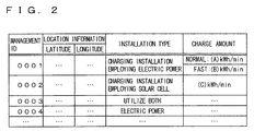
- Geographical map database 1020 stores the geographical map information used for known navigation devices as well as information about charging stations as shown in FIG. 2 .
- geographical map database 1020 stores, as the information about the charging stations, management IDs (identifications) of the charging stations, location information (latitude data and longitude data) of the charging stations, installation type information of the charging stations, and information about a charge amount (charging performance) per unit time provided by each charging station.
- geographical map database 1020 stores information that a charging station having a management ID “0001” is a charging installation that employs electric power (the electric power herein refers to electric power supplied by an electric power company having a power plant and electric power transmission equipment) and has a charging performance of (A) kWh/min (as one example of unit time, “minute” is employed herein) for normal charging and has a charging performance of (B) kWh/min for fast charging.
- geographical map database 1020 stores information that a charging station having a management ID “0002” is a charging installation including a solar cell, and has a charging performance of (C) kWh/min.
- a charging station having a management ID “0003” there may be used a combination type charging installation that employs both electric power (the electric power herein refers to electric power supplied by an electric power company having a power plant and electric power transmission equipment) and electric power generated by a solar cell. It is preferable if information about charging fees is stored in addition to the charging performances, because the user selects a charging station for a lower price readily.
- the vehicle's battery can accept electric power greater than the electric power attained by the charging performances (charge amount per unit time) of the charging stations.
- the battery serving as a power storage mechanism of the vehicle has a performance of accepting charge equal to or greater than the maximal charge amount per unit time.
- a charging station that does not satisfy this condition, such a charging station is excluded from charging stations displayed on display device 1040 , with the charging performance for the vehicle being stored separately.
- ECU 1030 identifies the location of the vehicle based on signals received from three or more GPS satellites via GPS antenna 1010 , and presents the location of the vehicle in a geographical map displayed on display device 1040 based on the geographical map information stored in geographical map database 1020 . In addition to such presentation, ECU 1030 presents information of charging installations in the geographical map displayed on display device 1040 as described later.
- Display device 1040 is configured to receive an input as to a user's desired scale of the geographical map via its touch panel. Further, if a charging station serving as a charging installation employs electric power generated by a solar cell, the generated electric power varies depending on a solar radiation amount (charging performance thereof also varies accordingly). Hence, display device 1040 is configured to be capable of receiving an input as to whether to make a request for correction based on the variation of the solar radiation amount in real time (real-time solar radiation correction request).
- display device 1040 is configured to be capable of receiving an input as to whether or not the user simply makes a request (presentation switching request) to switch from a screen presenting charging performances of charging stations each serving as a charging installation to a screen presenting charging time required to charge the battery of the vehicle fully or up to 80% from the remaining amount.
- Battery ECU 2000 uses, for example, an SOC as a management indicator to control charging/discharging of the battery mounted on the vehicle and used for traveling.
- the SOC is calculated by battery ECU 2000 when it integrates values of open voltage of the battery or values of charging current to the battery.
- Solar radiation amount detecting unit 3000 is attached to, for example, a windshield to detect a degree of solar radiation. Note that solar radiation amount detecting unit 3000 may be adapted to communicate with a server device distributing weather information, in order to acquire information regarding a solar radiation amount during traveling of the vehicle or information regarding a solar radiation amount in a location where the vehicle is expected to travel.
- Controlling the presentation for a charging station in such a navigation device can be implemented by hardware mainly utilizing digital circuit or analog circuit configurations, or software mainly utilizing a CPU (Central Processing Unit) and a memory included in ECU 1030 and a program read out from the memory and executed by the CPU.
- a CPU Central Processing Unit
- a memory included in ECU 1030 and a program read out from the memory and executed by the CPU.
- a program read out from the memory and executed by the CPU Generally, it is said that when implemented by hardware, it is advantageous in terms of operation speed, and when implemented by software, it is beneficial in terms of design change.
- a recording medium having such a program recorded thereon is also an embodiment of the present invention.
- this program is a subroutine, and is repeatedly executed at a predetermined cycle time. Note also that in this program, only processes for controlling the presentation of the charging stations in navigation device 1000 are described.
- step 1000 ECU 1030 detects the present location of the vehicle based on data received from the GPS satellites via GPS antenna 1010 .
- ECU 1030 reads out from geographical map database 1020 geographical map data indicating a region proximate to the present location.
- the geographical map data indicating the region proximate to the present location is determined and read out from geographical map database 1020 in conjunction with a scale on which the geographical map data is requested to be displayed.
- ECU 1030 presents the locations of the charging installations (charging stations) and the location of the vehicle on display device 1040 over the geographical map information thus read out. In this way, on display device 1040 , together with the geographical map information, the location of the vehicle, the locations of the charging installations, and their charging performances are displayed.
- ECU 1030 determines whether or not the user has requested presentation switching. Specifically, it is determined from whether or not a “presentation switching” button set at the touch panel of display device 1040 has been pressed. Note that it is assumed that this presentation switching corresponds to a switching request from presentation of “charging performances per unit time” to presentation of “charging time required to fully charge or charge up to an SOC of 80%”. If the presentation switching request is detected (YES in S 1030 ), the process goes to S 1040 . If not (NO in S 1030 ), this process (subroutine) is terminated.
- the presentation switching may correspond to a switching request from presentation of “charging performance per unit time that is based on a standard performance of a solar cell” to presentation of “charging performance per unit time that is based on a solar cell's performance that is in consideration of a solar radiation amount at the present moment”.
- ECU 1030 determines whether or not there is a charging installation employing solar light in the displayed region. On this occasion, whether or not there is a charging installation employing solar light is determined from geographical map database 1020 shown in FIG. 2 based on the location information and installation types of the charging installations. If it is determined that there is a charging installation employing solar light in the displayed region (YES in S 1040 ), the process goes to S 1050 . If not (NO in S 1040 ), the process goes to S 1080 .
- ECU 1030 determines whether or not a request (real-time solar radiation correction request) has been made to correct variation of an amount of electric power generated by the solar cell and present a charging performance in real time. It is assumed that whether to make a real-time solar radiation correction request can be set through an initial setting screen of navigation device 1000 .
- ECU 1030 detects a solar radiation amount at the present moment in the vicinity of the vehicle based on a solar radiation amount detection signal received from solar radiation amount detecting unit 3000 . If information for a charging station located away from the location of the vehicle (distant away to such an extent that the solar radiation amount differs between their locations) and employing a solar cell is to be presented on display device 1040 , the solar radiation amount in the vicinity of the charging station is detected based on information received from the server device distributing weather information.
- ECU 1030 corrects the charge amount per unit time provided by the charging installation employing solar light.
- the charge amount is corrected as follows, for example. That is, in geographical map database 1020 shown in FIG. 2 , a charge amount per unit time (charging performance) provided by the charging station employing the solar cell is correlated with a specific solar radiation amount and is stored as a performance of 100%, and a ratio of decrease in generated electric power is calculated from the detected solar radiation amount.
- ECU 1030 detects an SOC in the battery of the vehicle at the present moment, based on information received from battery ECU 2000 .
- ECU 1030 calculates a discharge amount of the battery based on a distance from the present location of the vehicle to each of the charging installations.
- ECU 1030 estimates an amount (discharge amount) of electric power discharged from the battery until the vehicle reaches each charging installation, based on the distance from the present location of the vehicle to each charging installation (if slope or traffic conditions are considered, it is more desirable in terms of precise determination of an actual discharge amount), using a separately stored traveling database (for example, a database in which a relation between a traveling pattern and an amount of charging/discharging electric power or an SOC is mapped).
- a separately stored traveling database for example, a database in which a relation between a traveling pattern and an amount of charging/discharging electric power or an SOC is mapped.
- ECU 1030 estimates an SOC in the battery left upon arrival of the vehicle at each charging installation, based on the detected present SOC of the vehicle and an estimated amount (discharge amount) of electric power discharged from the battery until the vehicle reaches each charging installation. From the SOC thus estimated, ECU 1030 calculates time required to charge up to a fully charged state (the fully charged state herein may refer to an SOC of 100% or an SOC of 80%, which is set as a so-called “control upper limit value” in a hybrid vehicle). It is assumed that correlating such a fully charged state to an SOC of a certain level can be set through the initial setting screen of navigation device 1000 .
- ECU 1030 calculates a required amount of electric power for charging, from shortage in an SOC (SOC to be achieved by charging). Using the required amount of electric power for charging and the charge amount per unit time (which may have been subjected to real time solar radiation amount correction in the case of a charging station employing a solar cell), ECU 1030 computes to determine time required to achieve the fully charge state.
- SOC SOC to be achieved by charging
- ECU 1030 presents the times required for charging in the geographical map, in association with displayed icons that represent the charging stations respectively.
- the following describes an operation performed by the navigation device according to the present embodiment based on the above-described structure and process of the flowchart under control of ECU 1030 .
- the location of the vehicle is detected based on data received from the GPS satellites (S 1000 ), geographical map data is read out from geographical map database 1020 in conjunction with a scale (S 1010 ), and the locations of the charging installations (charging stations) and the location of the vehicle are presented in the geographical map on display device 1040 (S 1020 ).
- FIG. 4 shows one example of the geographical map displayed on display device 1040 on this occasion.
- the charging installations having the management IDs “0001” and “0002” in the geographical map database of FIG. 2 are displayed as icons. Also, their charging performances, which have not been subjected to real time solar radiation amount correction, are presented.
- the presentation switching button (for use in the touch panel) is displayed.
- an image is displayed to represent an amount of charge in the battery.
- a solar radiation amount is detected (S 1060 ).
- a charge amount per unit time is corrected based on an amount of electric power generated based on the detected solar radiation amount, relative to an amount of generated electric power corresponding to a standard (or maximal) solar radiation amount (S 1070 ).
- An SOC in the battery at the present moment (assuming that the vehicle has not reached the charging installation yet) is detected (S 1080 ), and a discharge amount of the battery until the vehicle reaches the charging installation is calculated from a distance to the charging installation in consideration of road slope conditions and traffic conditions (S 1090 ).
- the SOC in the battery upon arrival of the vehicle at the charging installation is estimated, and from the SOC thus estimated, charging time required to achieve the fully charged state (SOC of 100% or 80%) is calculated (S 1100 ).
- required charging time is calculated based on the charging performance actually achievable based on the solar radiation amount at the present moment by the charging installation employing the solar cell.
- the time required for charging is presented in association with each of the locations of the icons representing the charging installations respectively (i.e., the locations in the geographical map) (S 1200 ).
- the charging time in the charging station having the management ID “0002” in FIG. 5 and employing a solar cell i.e., in the information indicating the charging time “fully charged for (c) time”
- the real time solar radiation amount correction, and the discharge amount of the battery during the traveling from the present location of the vehicle to the charging station are taken into consideration.
- a navigation device allows a vehicle's user to readily select a charging station when a battery thereof needs to be charged at an outside location or when there are a plurality of charging stations in the vicinity of his/her destination. Accordingly, it can be readily determine, for example, how long charging time is required to charge the battery using a charging station that employs a solar cell which generates a varying amount of electric power depending on weather, when the vehicle has not reached the charging station yet.
- a real-time solar radiation correction request button may be displayed.
- the real-time solar radiation correction request button is pressed, not the charging time but the charging performance having been through solar radiation correction may be presented in the case of the charging station employing the solar cell.
- the vehicle may be a hybrid vehicle, an electric vehicle, or a fuel-cell vehicle as long as it is a vehicle having a power storage mechanism (a battery or a capacitor) for supplying electric power to a motor serving as a driving source for traveling and has a function allowing the power storage mechanism to be charged using an external power source.
- the power storage mechanism is a battery (secondary battery).
- the solar cell mounted on the vehicle is capable of charging the battery and supplying electric power to the motor serving as a driving source for traveling.
- the vehicle in the present embodiment has the solar cell mounted thereon and a solar radiation amount therefore always needs to be considered upon charging the battery with electric power generated by the solar cell mounted on the vehicle, it is set in the initial state that the real-time solar radiation correction request described in the first embodiment is to be made.
- FIG. 6 shows a control block diagram corresponding to FIG. 1 and illustrating a vehicle including a navigation device 1100 according to the present embodiment.
- elements having the same functions as those of elements in FIG. 1 are given the same reference characters. Hence, detailed explanation therefor is not repeated here.
- a geographical map database 2020 has the same hardware configuration as that of geographical map database 1020 but stores different data. A difference between the databases will be described later.
- an ECU 2030 has the same hardware configuration as that of ECU 1030 but executes a different program. A difference between the programs will be described later. Since the configurations are different as such, navigation device 1100 is distinguished from navigation device 1000 of the first embodiment described above.
- the vehicle includes navigation device 1000 , a battery ECU 2000 , a solar radiation amount detecting unit 3000 , and a solar cell ECU 4000 for controlling the solar cell mounted on the vehicle.
- Solar cell ECU 4000 controls the solar cell mounted on the vehicle. For example, solar cell ECU 4000 informs ECU 2030 of an amount of generated electric power and electric power generation efficiency.
- geographical map database 2020 stores, in addition to the information stored in geographical map database 1020 described above, information about a charge amount attained in a parking lot based on electric power generated by the solar cell mounted on the vehicle.
- geographical map database 2020 the battery can be charged at daytime while the vehicle having the solar cell is parked.
- parking lots are regarded as charging stations.
- geographical map database 2020 stores management IDs, location information (latitude data and longitude data) of the parking lots each serving as a charging station, information indicating installation types of the charging stations as a parking lot, and information about a charge amount per unit time (charging performance) attained in each parking lot by the solar cell mounted on the vehicle.
- solar radiation of 100% may not be obtained (for example, in an area between buildings or in an underground parking lot provided with only an artificial light source).
- the ratio of the solar radiation amount is stored in percentage. It should be noted that underground parking lots can be excluded from the managed parking lots.
- a charging station shown in FIG. 7 and having a management ID “1003” is a parking lot irradiated with solar light well (the ratio of a solar radiation amount is 100%) and is managed as a charging station allowing the solar cell mounted on the vehicle to achieve a charging performance of (D) kWh/min.
- a charging station having a management ID “1004” is a parking lot located between buildings but irradiated with solar light tolerably (the ratio of a solar radiation amount is 80%), and is managed as a charging station allowing the solar cell mounted on the vehicle to achieve a charging performance of (E) kWh/min. It is preferable if the database is adapted to store information regarding parking fees in addition to the information indicating the charging performances, because the user readily selects a more inexpensive parking lot providing a good charging performance.
- ECU 2030 determines whether or not a charging installation including a parking lot and employing solar light exists in the displayed region. Whether or not there is a charging installation including a parking lot and employing solar light is determined from geographical map database 2020 shown in FIG. 6 based on the location information and installation types of the charging installations. If it is determined that a charging installation including a parking lot and employing solar light is in the displayed region (YES in S 2000 ), the process goes to S 1060 . If not (NO in S 2000 ), the process goes to S 1080 .
- ECU 2030 corrects, based on the detected solar radiation amount, a charge amount per unit time provided by the charging installation including a parking lot and employing solar light. For example, a charge amount per unit time (charging performance) provided in a charging station (parking lot) by the solar cell mounted on the vehicle is correlated with a specific solar radiation amount and stored as a performance of 100% in geographical map database 2020 shown in FIG. 7 . From the detected solar radiation amount, a ratio of decrease in generated electric power is calculated to correct the charge amount.
- the parking lot having the management ID “ 1004 ” and managed as a charging installation in which only 80% of the solar cell mounted on the vehicle can be used for electric power generation only allows for a power generation performance of 48%, found by multiplying 80% by 60%.
- ECU 2030 calculates a charge/discharge amount of the battery based on a distance from the present location of the vehicle to each charging installation and in consideration of traffic conditions. On this occasion, ECU 2030 estimates an amount (discharge amount) of electric power discharged from the battery until the vehicle reaches each charging installation, based on the distance from the present location of the vehicle to each charging installation (if slope or traffic conditions are considered, it is more desirable in terms of precise determination of an actual discharge amount), using a separately stored traveling database (for example, a database in which a relation between a traveling pattern and an amount of charging/discharging electric power or an SOC is mapped).
- a separately stored traveling database for example, a database in which a relation between a traveling pattern and an amount of charging/discharging electric power or an SOC is mapped.
- ECU 2030 calculates an amount of electric power generated by the solar cell mounted on the vehicle while the vehicle is traveling.
- a SOC in the battery upon arrival at each charging installation can be estimated based on the detected SOC of the vehicle at the present moment (before reaching the parking lot serving as a charging installation) as well as an estimated discharge amount from the battery and an estimated amount of charge provided by the solar cell mounted on the vehicle until the vehicle reaches each charging installation, and charging time required to achieve the fully charged state can be calculated from the estimated SOC.
- the following describes an operation performed by the navigation device according to the present embodiment based on the above-described structure and the process of the flowchart, under control of ECU 2030 .
- the location of the vehicle is detected based on data received from the GPS satellites (S 1000 ), geographical map data is read out from geographical map database 1020 in conjunction with a scale (S 1010 ), and the locations of the charging installations (charging stations) including a parking lot and the location of the vehicle are presented in the geographical map on display device 1040 (S 1020 ).
- FIG. 9 shows one example of the geographical map displayed on display device 1040 on this occasion.
- charging installations having management IDs “ 0001 ” and “0002” in the geographical map database of FIG. 7 are displayed as icons.
- the charging installations having the management IDs “1003” and “1004” are displayed as icons. It should be noted that an open-air parking lot corresponds to a charge amount attained in the charging installation having the management ID “1003”, and a convenience store's parking lot corresponds to a charge amount attained in the charging installation having the management ID “1004”.
- a presentation switching button (for use in the touch panel) is displayed, whereas on the upper left side of the screen of display device 1040 , an image is displayed to represent an amount of charge in the battery.
- a solar radiation amount is detected (S 1060 ).
- a charge amount per unit time is corrected based on an amount of electric power generated based on the detected solar radiation amount, relative to an amount of generated electric power corresponding to a standard (or maximal) solar radiation amount (S 1070 ).
- the SOC in the battery at the present moment (assuming that the vehicle has not reached the charging installation yet) is detected (S 1080 ), and a discharge amount of the battery and a charge amount (having been subjected to real time solar radiation amount correction) attained by the solar cell mounted on the vehicle until arrival at the charging installation are calculated in consideration of a distance to the charging installation and traffic conditions (S 2020 ).
- An SOC in the battery upon the arrival at the charging installation is estimated, and charging time required for charging up to the fully charged state (SOC of 100% or 80%) is calculated from the SOC thus estimated (S 1100 ).
- the time required for charging is presented in association with the location of the icon representing each charging installation (i.e., location in the geographical map) as shown in FIG. 10 (S 1200 ).
- the charging station having the management ID “0001” is a charging installation that employs electric power (the “electric power” herein refers to electric power supplied from an electric power company having a power plant and electric power transmission equipment) and the vehicle has the solar cell mounted thereon.
- the solar cell mounted on the vehicle is added and is reflected in the displayed normal charging time and fast charging time thereof (the displayed charging time is shorter than the charging time required by a vehicle having no solar cell).
- the charging station having the management ID “ 0002 ” is a charging installation employing a solar cell provided in the charging installation, and the vehicle has the solar cell mounted thereon. Hence, a charge amount provided by the solar cell mounted on the vehicle is added and is reflected in the displayed charging time (the displayed charging time is shorter than the charging time required by a vehicle having no solar cell).
- a navigation device allows the vehicle's user to readily select a charging station including a parking lot. This allows the user to readily determine how long charging time is required if, for example, a charging station employing a solar cell generating electric power that varies depending on weather is used, when the vehicle has not reached the charging station yet, in consideration of a charge amount provided by the solar cell mounted on the vehicle.
- a part of control in the second embodiment may be considered (only a road slope is considered, only traffic conditions are considered, only real time solar radiation correction is considered, or the like).
- the present invention is applicable to a vehicle that has a power storage mechanism mounted thereon to supply electric power to a motor serving as a driving source for traveling and has a function allowing the power storage mechanism to be charged using an external power source.
Abstract
Description
Claims (21)
Applications Claiming Priority (3)
| Application Number | Priority Date | Filing Date | Title |
|---|---|---|---|
| JP2007192185A JP4365429B2 (en) | 2007-07-24 | 2007-07-24 | Navigation device for displaying charging information and vehicle equipped with the device |
| JP2007-192185 | 2007-07-24 | ||
| PCT/JP2008/062038 WO2009013980A1 (en) | 2007-07-24 | 2008-06-26 | Navigation system for displaying charge information and vehicle including the system |
Publications (2)
| Publication Number | Publication Date |
|---|---|
| US20100169008A1 US20100169008A1 (en) | 2010-07-01 |
| US8301365B2 true US8301365B2 (en) | 2012-10-30 |
Family
ID=40281239
Family Applications (1)
| Application Number | Title | Priority Date | Filing Date |
|---|---|---|---|
| US12/451,800 Active 2029-04-04 US8301365B2 (en) | 2007-07-24 | 2008-06-26 | Navigation device presenting information regarding charging and vehicle including same device |
Country Status (5)
| Country | Link |
|---|---|
| US (1) | US8301365B2 (en) |
| EP (1) | EP2175239B1 (en) |
| JP (1) | JP4365429B2 (en) |
| CN (1) | CN101779099B (en) |
| WO (1) | WO2009013980A1 (en) |
Cited By (39)
| Publication number | Priority date | Publication date | Assignee | Title |
|---|---|---|---|---|
| US20110015819A1 (en) * | 2009-07-16 | 2011-01-20 | Aisin Aw Co., Ltd. | Guidance device, guidance method, and guidance program |
| US20110227532A1 (en) * | 2010-03-19 | 2011-09-22 | Aisin Aw Co., Ltd. | Driving support device, method, and program |
| US20120123676A1 (en) * | 2010-11-17 | 2012-05-17 | Honda Motor Co., Ltd. | In-vehicle navigation in collaboration with a server |
| US8725330B2 (en) | 2010-06-02 | 2014-05-13 | Bryan Marc Failing | Increasing vehicle security |
| US8862304B2 (en) | 2011-07-26 | 2014-10-14 | Gogoro, Inc. | Apparatus, method and article for providing vehicle diagnostic data |
| US8862388B2 (en) | 2011-07-26 | 2014-10-14 | Gogoro, Inc. | Apparatus, method and article for providing locations of power storage device collection, charging and distribution machines |
| US8878487B2 (en) | 2011-07-26 | 2014-11-04 | Gogoro, Inc. | Apparatus, method and article for providing to a user device information regarding availability of portable electrical energy storage devices at a portable electrical energy storage device collection, charging and distribution machine |
| US20140340048A1 (en) * | 2011-12-16 | 2014-11-20 | Pioneer Corporation | Facility information presentation device and facility information presentation method |
| US9123035B2 (en) | 2011-04-22 | 2015-09-01 | Angel A. Penilla | Electric vehicle (EV) range extending charge systems, distributed networks of charge kiosks, and charge locating mobile apps |
| US9121718B2 (en) * | 2011-11-21 | 2015-09-01 | Honda Motor Co., Ltd. | Method and system for improved vehicle navigation |
| US9124085B2 (en) | 2013-11-04 | 2015-09-01 | Gogoro Inc. | Apparatus, method and article for power storage device failure safety |
| US9129461B2 (en) | 2011-07-26 | 2015-09-08 | Gogoro Inc. | Apparatus, method and article for collection, charging and distributing power storage devices, such as batteries |
| US9132746B2 (en) | 2013-08-15 | 2015-09-15 | Honda Motor Co., Ltd. | Method and system for reducing range anxiety |
| US9151631B2 (en) | 2013-10-14 | 2015-10-06 | Ford Global Technologies, Llc | Vehicle fueling route planning |
| US9182244B2 (en) | 2011-07-26 | 2015-11-10 | Gogoro Inc. | Apparatus, method and article for authentication, security and control of power storage devices, such as batteries |
| US9216687B2 (en) | 2012-11-16 | 2015-12-22 | Gogoro Inc. | Apparatus, method and article for vehicle turn signals |
| US9275505B2 (en) | 2011-07-26 | 2016-03-01 | Gogoro Inc. | Apparatus, method and article for physical security of power storage devices in vehicles |
| US9390566B2 (en) | 2013-11-08 | 2016-07-12 | Gogoro Inc. | Apparatus, method and article for providing vehicle event data |
| US9407024B2 (en) | 2014-08-11 | 2016-08-02 | Gogoro Inc. | Multidirectional electrical connector, plug and system |
| US9424697B2 (en) | 2011-07-26 | 2016-08-23 | Gogoro Inc. | Apparatus, method and article for a power storage device compartment |
| US9437058B2 (en) | 2011-07-26 | 2016-09-06 | Gogoro Inc. | Dynamically limiting vehicle operation for best effort economy |
| US20170012580A1 (en) * | 2014-01-22 | 2017-01-12 | Hitachi, Ltd. | Photovoltaic Power Generator Output Estimation Method and Device, and Power System Monitoring Device Using Same |
| US9552682B2 (en) | 2011-07-26 | 2017-01-24 | Gogoro Inc. | Apparatus, method and article for redistributing power storage devices, such as batteries, between collection, charging and distribution machines |
| US9597973B2 (en) | 2011-04-22 | 2017-03-21 | Angel A. Penilla | Carrier for exchangeable batteries for use by electric vehicles |
| USD789883S1 (en) | 2014-09-04 | 2017-06-20 | Gogoro Inc. | Collection, charging and distribution device for portable electrical energy storage devices |
| US9770996B2 (en) | 2013-08-06 | 2017-09-26 | Gogoro Inc. | Systems and methods for powering electric vehicles using a single or multiple power cells |
| US9830753B2 (en) | 2011-07-26 | 2017-11-28 | Gogoro Inc. | Apparatus, method and article for reserving power storage devices at reserving power storage device collection, charging and distribution machines |
| US9837842B2 (en) | 2014-01-23 | 2017-12-05 | Gogoro Inc. | Systems and methods for utilizing an array of power storage devices, such as batteries |
| US9841463B2 (en) | 2014-02-27 | 2017-12-12 | Invently Automotive Inc. | Method and system for predicting energy consumption of a vehicle using a statistical model |
| US10040359B2 (en) | 2014-09-04 | 2018-08-07 | Gogoro Inc. | Apparatus, system, and method for vending, charging, and two-way distribution of electrical energy storage devices |
| US10055911B2 (en) | 2011-07-26 | 2018-08-21 | Gogoro Inc. | Apparatus, method and article for authentication, security and control of power storage devices, such as batteries, based on user profiles |
| US10065525B2 (en) | 2013-08-06 | 2018-09-04 | Gogoro Inc. | Adjusting electric vehicle systems based on an electrical energy storage device thermal profile |
| US10186094B2 (en) | 2011-07-26 | 2019-01-22 | Gogoro Inc. | Apparatus, method and article for providing locations of power storage device collection, charging and distribution machines |
| US20190165589A1 (en) * | 2017-11-24 | 2019-05-30 | Toyota Jidosha Kabushiki Kaisha | Vehicle |
| US10421462B2 (en) | 2015-06-05 | 2019-09-24 | Gogoro Inc. | Systems and methods for vehicle load detection and response |
| US10839451B2 (en) | 2011-04-22 | 2020-11-17 | Emerging Automotive, Llc | Systems providing electric vehicles with access to exchangeable batteries from available battery carriers |
| US11075530B2 (en) | 2013-03-15 | 2021-07-27 | Gogoro Inc. | Modular system for collection and distribution of electric storage devices |
| US11222485B2 (en) | 2013-03-12 | 2022-01-11 | Gogoro Inc. | Apparatus, method and article for providing information regarding a vehicle via a mobile device |
| US11710105B2 (en) | 2013-03-12 | 2023-07-25 | Gogoro Inc. | Apparatus, method and article for changing portable electrical power storage device exchange plans |
Families Citing this family (127)
| Publication number | Priority date | Publication date | Assignee | Title |
|---|---|---|---|---|
| JP5083975B2 (en) * | 2008-04-07 | 2012-11-28 | 本田技研工業株式会社 | Fuel cell vehicle |
| US8266075B2 (en) | 2008-06-16 | 2012-09-11 | International Business Machines Corporation | Electric vehicle charging transaction interface for managing electric vehicle charging transactions |
| US7991665B2 (en) * | 2008-06-16 | 2011-08-02 | International Business Machines Corporation | Managing incentives for electric vehicle charging transactions |
| US9751416B2 (en) | 2008-06-16 | 2017-09-05 | International Business Machines Corporation | Generating energy transaction plans |
| US8498763B2 (en) | 2008-06-16 | 2013-07-30 | International Business Machines Corporation | Maintaining energy principal preferences in a vehicle |
| US8531162B2 (en) | 2008-06-16 | 2013-09-10 | International Business Machines Corporation | Network based energy preference service for managing electric vehicle charging preferences |
| EP2329559A4 (en) | 2008-08-18 | 2017-10-25 | Christopher B. Austin | Vehicular battery charger, charging system, and method |
| US8918336B2 (en) | 2008-08-19 | 2014-12-23 | International Business Machines Corporation | Energy transaction broker for brokering electric vehicle charging transactions |
| US8725551B2 (en) | 2008-08-19 | 2014-05-13 | International Business Machines Corporation | Smart electric vehicle interface for managing post-charge information exchange and analysis |
| US8918376B2 (en) | 2008-08-19 | 2014-12-23 | International Business Machines Corporation | Energy transaction notification service for presenting charging information of an electric vehicle |
| US8103391B2 (en) * | 2008-08-19 | 2012-01-24 | International Business Machines Corporation | System for detecting interrupt conditions during an electric vehicle charging process |
| US20100049533A1 (en) * | 2008-08-19 | 2010-02-25 | International Business Machines Corporation | Executing an Energy Transaction Plan for an Electric Vehicle |
| JP5577610B2 (en) * | 2009-03-10 | 2014-08-27 | 日産自動車株式会社 | Facility information presentation apparatus and facility information presentation method |
| JP5402185B2 (en) * | 2009-04-13 | 2014-01-29 | 株式会社デンソー | Charge monitoring device, electric vehicle, and server |
| KR101664203B1 (en) * | 2009-05-12 | 2016-10-10 | 삼성전자 주식회사 | Apparatus and method for ofering charge information of a portable terminal having a solar battery |
| JP2010281715A (en) * | 2009-06-05 | 2010-12-16 | J&K Car Electronics Corp | In-vehicle device, display control method, and program |
| JP5424311B2 (en) * | 2009-06-18 | 2014-02-26 | アルパイン株式会社 | Parking lot information provision device |
| JP5560788B2 (en) * | 2009-06-26 | 2014-07-30 | 日産自動車株式会社 | Information provision device |
| JP2011027472A (en) * | 2009-07-22 | 2011-02-10 | Toyota Central R&D Labs Inc | Route search apparatus, program, start frequency prediction apparatus, fuel consumption calculation apparatus, and operation schedule determination apparatus |
| KR101607266B1 (en) * | 2009-08-31 | 2016-03-29 | 엘지전자 주식회사 | Mobile terminal |
| US9134136B2 (en) * | 2010-01-26 | 2015-09-15 | Mitsubishi Electric Corporation | Navigation apparatus, vehicle information display apparatus, and vehicle information display system |
| US9299093B2 (en) * | 2010-01-29 | 2016-03-29 | GM Global Technology Operations LLC | Method for charging a plug-in electric vehicle |
| JP5304673B2 (en) * | 2010-02-02 | 2013-10-02 | 株式会社デンソー | Navigation device |
| KR101190748B1 (en) * | 2010-02-03 | 2012-10-12 | 엘지전자 주식회사 | Television which is equip with funtion of monitoring for Solar Cell Module |
| JP2011163987A (en) * | 2010-02-11 | 2011-08-25 | Denso Corp | Sunlight information collecting system and sunlight information transmitter |
| WO2011098195A1 (en) * | 2010-02-15 | 2011-08-18 | Tomtom International B.V. | Methods and systems for obtaining charging location information |
| WO2011102515A1 (en) | 2010-02-22 | 2011-08-25 | トヨタ自動車株式会社 | Power supply control device and information provision device |
| JP5408002B2 (en) * | 2010-03-31 | 2014-02-05 | アイシン・エィ・ダブリュ株式会社 | Map display device, map display method, and map display program |
| WO2011121790A1 (en) * | 2010-03-31 | 2011-10-06 | パイオニア株式会社 | Search device, navigation device, information providing device, search method, search program, and recording medium |
| JP5499872B2 (en) * | 2010-04-21 | 2014-05-21 | ソニー株式会社 | Battery control device, battery control method and program |
| US8386169B2 (en) * | 2010-04-29 | 2013-02-26 | Telenav, Inc. | Navigation system with route planning and method of operation thereof |
| JP5657912B2 (en) * | 2010-05-06 | 2015-01-21 | クラリオン株式会社 | Navigation device |
| JP5614097B2 (en) * | 2010-05-19 | 2014-10-29 | トヨタ自動車株式会社 | Solar power information device |
| DE102010030309A1 (en) | 2010-06-21 | 2011-12-22 | Ford Global Technologies, Llc | Method and device for determining an energy consumption optimized route |
| US8035341B2 (en) * | 2010-07-12 | 2011-10-11 | Better Place GmbH | Staged deployment for electrical charge spots |
| WO2012012008A2 (en) * | 2010-07-23 | 2012-01-26 | Electric Transportation Engineering Corp. | System for advertising and communicating at a vehicle charging station and method of using the same |
| CN101945328A (en) * | 2010-09-07 | 2011-01-12 | 广东电网公司电力科学研究院 | Positioning information system for charging device of electric vehicle and implementing method thereof |
| US8793148B2 (en) * | 2010-09-17 | 2014-07-29 | Robert Leroy Wise | Fuel distribution network |
| KR20120036563A (en) * | 2010-10-08 | 2012-04-18 | 현대자동차주식회사 | Nevigation system for electric vehicle and service method of the same |
| DE102010042411A1 (en) * | 2010-10-13 | 2012-04-19 | Robert Bosch Gmbh | Navigation system for cabriolet, has route determination device determining target guidance route from starting point to target point by considering solar altitudes, and providing guidance route to user using input and/or output device |
| US9030048B2 (en) | 2010-10-18 | 2015-05-12 | Alpha Technologies Inc. | Uninterruptible power supply systems and methods for communications systems |
| US20110225105A1 (en) * | 2010-10-21 | 2011-09-15 | Ford Global Technologies, Llc | Method and system for monitoring an energy storage system for a vehicle for trip planning |
| US20120109519A1 (en) * | 2010-10-27 | 2012-05-03 | Honda Motor Co., Ltd. | System and method for routing bev to charging station |
| JP5656624B2 (en) * | 2010-12-28 | 2015-01-21 | 三菱重工業株式会社 | Road traffic flow simulation apparatus, road traffic flow simulation program, and road traffic flow simulation method |
| US20120179323A1 (en) * | 2011-01-06 | 2012-07-12 | Ford Global Technologies, Llc | Method and Apparatus for Charging Station Guidance |
| US20110224852A1 (en) * | 2011-01-06 | 2011-09-15 | Ford Global Technologies, Llc | Methods and system for selectively charging a vehicle |
| US8849499B2 (en) * | 2011-01-06 | 2014-09-30 | Ford Global Technologies, Llc | Methods and systems for monitoring a vehicle's energy source |
| CN103339664B (en) * | 2011-02-03 | 2015-07-29 | 日本电气株式会社 | Charger arrangement plan supportive device, charger arrangement plan support method |
| JP5668513B2 (en) * | 2011-02-16 | 2015-02-12 | トヨタ自動車株式会社 | Charging support device |
| US20120239594A1 (en) * | 2011-03-17 | 2012-09-20 | John Christopher Boot | Apparatus and methods for providing demand response information |
| JP5760625B2 (en) * | 2011-04-13 | 2015-08-12 | トヨタ自動車株式会社 | Center server and charging facility registration system including the same |
| JP2012226416A (en) * | 2011-04-15 | 2012-11-15 | Toyota Motor Corp | Charging system |
| US9215274B2 (en) | 2011-04-22 | 2015-12-15 | Angel A. Penilla | Methods and systems for generating recommendations to make settings at vehicles via cloud systems |
| US9371007B1 (en) | 2011-04-22 | 2016-06-21 | Angel A. Penilla | Methods and systems for automatic electric vehicle identification and charging via wireless charging pads |
| US10572123B2 (en) | 2011-04-22 | 2020-02-25 | Emerging Automotive, Llc | Vehicle passenger controls via mobile devices |
| US9139091B1 (en) | 2011-04-22 | 2015-09-22 | Angel A. Penilla | Methods and systems for setting and/or assigning advisor accounts to entities for specific vehicle aspects and cloud management of advisor accounts |
| US9493130B2 (en) | 2011-04-22 | 2016-11-15 | Angel A. Penilla | Methods and systems for communicating content to connected vehicle users based detected tone/mood in voice input |
| US9189900B1 (en) | 2011-04-22 | 2015-11-17 | Angel A. Penilla | Methods and systems for assigning e-keys to users to access and drive vehicles |
| US11370313B2 (en) | 2011-04-25 | 2022-06-28 | Emerging Automotive, Llc | Methods and systems for electric vehicle (EV) charge units and systems for processing connections to charge units |
| US10824330B2 (en) | 2011-04-22 | 2020-11-03 | Emerging Automotive, Llc | Methods and systems for vehicle display data integration with mobile device data |
| US9581997B1 (en) | 2011-04-22 | 2017-02-28 | Angel A. Penilla | Method and system for cloud-based communication for automatic driverless movement |
| US9346365B1 (en) | 2011-04-22 | 2016-05-24 | Angel A. Penilla | Methods and systems for electric vehicle (EV) charging, charging unit (CU) interfaces, auxiliary batteries, and remote access and user notifications |
| US9171268B1 (en) | 2011-04-22 | 2015-10-27 | Angel A. Penilla | Methods and systems for setting and transferring user profiles to vehicles and temporary sharing of user profiles to shared-use vehicles |
| US11203355B2 (en) | 2011-04-22 | 2021-12-21 | Emerging Automotive, Llc | Vehicle mode for restricted operation and cloud data monitoring |
| US9104537B1 (en) | 2011-04-22 | 2015-08-11 | Angel A. Penilla | Methods and systems for generating setting recommendation to user accounts for registered vehicles via cloud systems and remotely applying settings |
| US9818088B2 (en) | 2011-04-22 | 2017-11-14 | Emerging Automotive, Llc | Vehicles and cloud systems for providing recommendations to vehicle users to handle alerts associated with the vehicle |
| US9963145B2 (en) | 2012-04-22 | 2018-05-08 | Emerging Automotive, Llc | Connected vehicle communication with processing alerts related to traffic lights and cloud systems |
| US9230440B1 (en) | 2011-04-22 | 2016-01-05 | Angel A. Penilla | Methods and systems for locating public parking and receiving security ratings for parking locations and generating notifications to vehicle user accounts regarding alerts and cloud access to security information |
| US10289288B2 (en) | 2011-04-22 | 2019-05-14 | Emerging Automotive, Llc | Vehicle systems for providing access to vehicle controls, functions, environment and applications to guests/passengers via mobile devices |
| US9229905B1 (en) | 2011-04-22 | 2016-01-05 | Angel A. Penilla | Methods and systems for defining vehicle user profiles and managing user profiles via cloud systems and applying learned settings to user profiles |
| US9180783B1 (en) | 2011-04-22 | 2015-11-10 | Penilla Angel A | Methods and systems for electric vehicle (EV) charge location color-coded charge state indicators, cloud applications and user notifications |
| US11270699B2 (en) | 2011-04-22 | 2022-03-08 | Emerging Automotive, Llc | Methods and vehicles for capturing emotion of a human driver and customizing vehicle response |
| US9348492B1 (en) | 2011-04-22 | 2016-05-24 | Angel A. Penilla | Methods and systems for providing access to specific vehicle controls, functions, environment and applications to guests/passengers via personal mobile devices |
| US9365188B1 (en) | 2011-04-22 | 2016-06-14 | Angel A. Penilla | Methods and systems for using cloud services to assign e-keys to access vehicles |
| US11294551B2 (en) | 2011-04-22 | 2022-04-05 | Emerging Automotive, Llc | Vehicle passenger controls via mobile devices |
| US10286919B2 (en) | 2011-04-22 | 2019-05-14 | Emerging Automotive, Llc | Valet mode for restricted operation of a vehicle and cloud access of a history of use made during valet mode use |
| US9288270B1 (en) | 2011-04-22 | 2016-03-15 | Angel A. Penilla | Systems for learning user preferences and generating recommendations to make settings at connected vehicles and interfacing with cloud systems |
| US11132650B2 (en) | 2011-04-22 | 2021-09-28 | Emerging Automotive, Llc | Communication APIs for remote monitoring and control of vehicle systems |
| US9809196B1 (en) | 2011-04-22 | 2017-11-07 | Emerging Automotive, Llc | Methods and systems for vehicle security and remote access and safety control interfaces and notifications |
| US9697503B1 (en) | 2011-04-22 | 2017-07-04 | Angel A. Penilla | Methods and systems for providing recommendations to vehicle users to handle alerts associated with the vehicle and a bidding market place for handling alerts/service of the vehicle |
| US9648107B1 (en) | 2011-04-22 | 2017-05-09 | Angel A. Penilla | Methods and cloud systems for using connected object state data for informing and alerting connected vehicle drivers of state changes |
| US9536197B1 (en) | 2011-04-22 | 2017-01-03 | Angel A. Penilla | Methods and systems for processing data streams from data producing objects of vehicle and home entities and generating recommendations and settings |
| US9718371B2 (en) | 2011-06-30 | 2017-08-01 | International Business Machines Corporation | Recharging of battery electric vehicles on a smart electrical grid system |
| JP5516525B2 (en) * | 2011-07-20 | 2014-06-11 | トヨタ自動車株式会社 | Driving assistance device |
| US20130041552A1 (en) | 2011-08-11 | 2013-02-14 | Ford Global Technologies, Llc | Methods and Apparatus for Estimating Power Usage |
| JP5704372B2 (en) * | 2011-08-12 | 2015-04-22 | トヨタ自動車株式会社 | Charging information providing device |
| US20130162430A1 (en) * | 2011-08-18 | 2013-06-27 | Wefi, Inc. | Method and System for Charging Mobile Devices |
| JP6109471B2 (en) * | 2011-09-26 | 2017-04-05 | 三菱重工業株式会社 | Charging infrastructure information providing system, charging infrastructure information providing apparatus, control method and program |
| US8907776B2 (en) | 2011-10-05 | 2014-12-09 | Ford Global Technologies, Llc | Method and apparatus for do not disturb message delivery |
| US20130090936A1 (en) * | 2011-10-07 | 2013-04-11 | James Solomon | Configurable Visibility of Electric Vehicle Charging Stations |
| US9037443B1 (en) * | 2011-10-16 | 2015-05-19 | Alpha Technologies Inc. | Systems and methods for solar power equipment |
| US9348381B2 (en) | 2011-10-19 | 2016-05-24 | Zeco Systems Pte Ltd | Methods and apparatuses for charging of electric vehicles |
| US8849742B2 (en) | 2012-01-24 | 2014-09-30 | Ford Global Technologies, Llc | Method and apparatus for providing charging state alerts |
| US8884784B2 (en) | 2012-04-30 | 2014-11-11 | Honda Motor Co., Ltd. | Solar charged automotive vehicle having means to determine a parking location |
| CN102721422A (en) * | 2012-06-01 | 2012-10-10 | 北京交通大学 | Intelligent guide system for power supply of electric automobile |
| US9929581B2 (en) | 2012-09-24 | 2018-03-27 | Nissan Motor Co., Ltd. | Charge control device and charge control method |
| US9462545B2 (en) | 2013-03-14 | 2016-10-04 | Ford Global Technologies, Llc | Method and apparatus for a battery saver utilizing a sleep and vacation strategy |
| US9066298B2 (en) | 2013-03-15 | 2015-06-23 | Ford Global Technologies, Llc | Method and apparatus for an alert strategy between modules |
| CN104076897B (en) * | 2013-03-28 | 2017-08-29 | 联想(北京)有限公司 | A kind of information processing method and electronic equipment |
| JP5746257B2 (en) * | 2013-04-30 | 2015-07-08 | トヨタ自動車株式会社 | Power generation output device, photovoltaic power generation system |
| US20150032661A1 (en) * | 2013-07-26 | 2015-01-29 | Recargo, Inc. | Scoring charging stations used by electric vehicles |
| GB2522648A (en) * | 2014-01-31 | 2015-08-05 | Nokia Technologies Oy | An apparatus, method and computer program for enabling charging of a vehicle |
| DE102014205341A1 (en) * | 2014-03-21 | 2015-09-24 | Volkswagen Aktiengesellschaft | Display method for a vehicle |
| WO2015189911A1 (en) * | 2014-06-10 | 2015-12-17 | 三菱電機株式会社 | Facility-information display control device, facility-information display control method, and facility-information display system |
| JP6531009B2 (en) * | 2015-08-19 | 2019-06-12 | 本田技研工業株式会社 | POWER SUPPLY CONTROL DEVICE, TRANSPORT EQUIPMENT, AND POWER SUPPLY CONTROL METHOD |
| KR20170069092A (en) * | 2015-12-10 | 2017-06-20 | 현대자동차주식회사 | Audio video navigation device and method for providing charging station information using the audio video navigation device |
| KR101875637B1 (en) * | 2016-04-19 | 2018-07-06 | 현대자동차 주식회사 | Charging station guide apparatus and method of the same |
| DE112016007143T5 (en) * | 2016-09-14 | 2019-04-25 | Ford Motor Company | SELF-PLANNED FUEL SUPPLY AUTONOMOUS VEHICLES |
| CN109689423B (en) | 2016-09-14 | 2023-06-06 | 福特汽车公司 | Autonomous vehicle fueling using centralized scheduling |
| WO2018084843A1 (en) * | 2016-11-03 | 2018-05-11 | Ford Motor Company | Renewable energy vehicle charging |
| JP2017130220A (en) * | 2017-03-07 | 2017-07-27 | 三菱重工業株式会社 | Charging infrastructure, user terminal, on-vehicle device, and electric vehicle |
| JP6893908B2 (en) * | 2017-03-07 | 2021-06-23 | 三菱重工業株式会社 | Charging infrastructure device |
| US10197412B2 (en) * | 2017-03-28 | 2019-02-05 | Ford Global Technologies, Llc | Electric vehicle charging |
| JP7152505B2 (en) * | 2017-12-28 | 2022-10-12 | 韋涛 | An electric vehicle navigation method and system that guides based on the amount of electricity in an energy storage charging station |
| CN107953798B (en) * | 2017-12-28 | 2020-07-24 | 北京万开天盛科技有限公司 | Electric vehicle navigation method and system based on energy storage charging pile electric quantity guidance |
| CN108237942B (en) * | 2018-01-15 | 2022-02-11 | 国网黑龙江省电力有限公司电力科学研究院 | Electric automobile rescue system and electric automobile rescue method |
| US10913360B2 (en) | 2018-02-13 | 2021-02-09 | Toyota Motor Engineering & Manufacturing North America, Inc. | Systems and methods of autonomous solar exposure |
| US10919522B2 (en) * | 2018-06-13 | 2021-02-16 | Fujitsu Limited | Automated exploitation of shade-giving structures |
| JP7243101B2 (en) * | 2018-09-25 | 2023-03-22 | トヨタ自動車株式会社 | Server, vehicle and charger guide method |
| KR20200095001A (en) * | 2019-01-31 | 2020-08-10 | 현대자동차주식회사 | Method for displaying a charging energy by a solar roof system of a vehicle |
| JP7218622B2 (en) * | 2019-03-08 | 2023-02-07 | 三菱自動車工業株式会社 | charging control system |
| WO2020208655A1 (en) * | 2019-04-11 | 2020-10-15 | Panasonic India Pvt. Ltd. | Charging of electric vehicles using renewable energy |
| JP7298306B2 (en) * | 2019-05-29 | 2023-06-27 | トヨタ自動車株式会社 | Information equipment, information providing system, information providing server and information providing method |
| KR102457266B1 (en) * | 2020-02-28 | 2022-10-20 | 현대모비스 주식회사 | Electric vehicle for sharing information with a display device |
| JP7334715B2 (en) * | 2020-11-30 | 2023-08-29 | トヨタ自動車株式会社 | Navigation server, navigation program, and navigation system |
| US11914840B2 (en) * | 2021-07-20 | 2024-02-27 | Rivian Ip Holdings, Llc | Charger map overlay and detail card |
| KR102613087B1 (en) * | 2021-08-20 | 2023-12-12 | 광주과학기술원 | Monitoring system for charging and discharging of electronic vehicle |
Citations (16)
| Publication number | Priority date | Publication date | Assignee | Title |
|---|---|---|---|---|
| JPH09210702A (en) | 1996-02-05 | 1997-08-15 | Fuji Heavy Ind Ltd | Navigation system for electric car |
| US5815824A (en) | 1995-03-06 | 1998-09-29 | Mitsubishi Jidosha Kogyo Kabushiki Kaisha | Navigation system for electric automobile |
| JP2000253504A (en) | 1999-02-25 | 2000-09-14 | Toyota Motor Corp | Vehicle fitted with solar battery |
| JP2000258174A (en) | 1999-03-12 | 2000-09-22 | Weather Service:Kk | Navigator, navigation system, weather condition server |
| JP2000353295A (en) | 1999-06-09 | 2000-12-19 | Toyota Motor Corp | Route guiding device for vehicle and its method and medium |
| JP2001215124A (en) | 2000-02-03 | 2001-08-10 | Fujitsu Ten Ltd | Navigation device, facility data memory media, and facility data supplying data |
| US20020156545A1 (en) * | 2000-01-28 | 2002-10-24 | Hideo Sekino | System and method for assisting planning of environment symbiosis district |
| JP2003262525A (en) | 2002-03-08 | 2003-09-19 | Nissan Motor Co Ltd | Charging stand information-supplying apparatus |
| US20040169489A1 (en) * | 2003-02-28 | 2004-09-02 | Raymond Hobbs | Charger, vehicle with charger, and method of charging |
| US20050027442A1 (en) * | 2003-07-31 | 2005-02-03 | Kelley Edward E. | Agenda replicator system and method for travelers |
| JP2005163584A (en) | 2003-12-01 | 2005-06-23 | Denso Corp | Fuel economy information supply system, fuel economy information server device, and on-vehicle control device |
| US20060186890A1 (en) * | 2003-06-27 | 2006-08-24 | The Furukawa Electric Co, Ltd. | Method for determining deterioration of accumulator battery, method for measuring internal impedance of secondary battery, equipment for measuring internal impedance of secondary battery, equipment for determining deterioration of secondary battery, and power supply system |
| JP2006327247A (en) | 2005-05-23 | 2006-12-07 | Toyota Motor Corp | Vehicle controller |
| US20070052552A1 (en) * | 2005-09-07 | 2007-03-08 | International Business Machines Corporation | Method and system for acquiring additional information of map information |
| JP2007116799A (en) | 2005-10-19 | 2007-05-10 | Leben Hanbai:Kk | Battery managing system |
| US20080211230A1 (en) * | 2005-07-25 | 2008-09-04 | Rexorce Thermionics, Inc. | Hybrid power generation and energy storage system |
Family Cites Families (2)
| Publication number | Priority date | Publication date | Assignee | Title |
|---|---|---|---|---|
| JP3177806B2 (en) * | 1993-09-17 | 2001-06-18 | 本田技研工業株式会社 | Display device for electric vehicle |
| JP3617105B2 (en) * | 1995-02-16 | 2005-02-02 | ソニー株式会社 | Electronic device and operation mode control method thereof |
-
2007
- 2007-07-24 JP JP2007192185A patent/JP4365429B2/en not_active Expired - Fee Related
-
2008
- 2008-06-26 US US12/451,800 patent/US8301365B2/en active Active
- 2008-06-26 CN CN2008800255817A patent/CN101779099B/en not_active Expired - Fee Related
- 2008-06-26 EP EP08777801.5A patent/EP2175239B1/en not_active Not-in-force
- 2008-06-26 WO PCT/JP2008/062038 patent/WO2009013980A1/en active Application Filing
Patent Citations (16)
| Publication number | Priority date | Publication date | Assignee | Title |
|---|---|---|---|---|
| US5815824A (en) | 1995-03-06 | 1998-09-29 | Mitsubishi Jidosha Kogyo Kabushiki Kaisha | Navigation system for electric automobile |
| JPH09210702A (en) | 1996-02-05 | 1997-08-15 | Fuji Heavy Ind Ltd | Navigation system for electric car |
| JP2000253504A (en) | 1999-02-25 | 2000-09-14 | Toyota Motor Corp | Vehicle fitted with solar battery |
| JP2000258174A (en) | 1999-03-12 | 2000-09-22 | Weather Service:Kk | Navigator, navigation system, weather condition server |
| JP2000353295A (en) | 1999-06-09 | 2000-12-19 | Toyota Motor Corp | Route guiding device for vehicle and its method and medium |
| US20020156545A1 (en) * | 2000-01-28 | 2002-10-24 | Hideo Sekino | System and method for assisting planning of environment symbiosis district |
| JP2001215124A (en) | 2000-02-03 | 2001-08-10 | Fujitsu Ten Ltd | Navigation device, facility data memory media, and facility data supplying data |
| JP2003262525A (en) | 2002-03-08 | 2003-09-19 | Nissan Motor Co Ltd | Charging stand information-supplying apparatus |
| US20040169489A1 (en) * | 2003-02-28 | 2004-09-02 | Raymond Hobbs | Charger, vehicle with charger, and method of charging |
| US20060186890A1 (en) * | 2003-06-27 | 2006-08-24 | The Furukawa Electric Co, Ltd. | Method for determining deterioration of accumulator battery, method for measuring internal impedance of secondary battery, equipment for measuring internal impedance of secondary battery, equipment for determining deterioration of secondary battery, and power supply system |
| US20050027442A1 (en) * | 2003-07-31 | 2005-02-03 | Kelley Edward E. | Agenda replicator system and method for travelers |
| JP2005163584A (en) | 2003-12-01 | 2005-06-23 | Denso Corp | Fuel economy information supply system, fuel economy information server device, and on-vehicle control device |
| JP2006327247A (en) | 2005-05-23 | 2006-12-07 | Toyota Motor Corp | Vehicle controller |
| US20080211230A1 (en) * | 2005-07-25 | 2008-09-04 | Rexorce Thermionics, Inc. | Hybrid power generation and energy storage system |
| US20070052552A1 (en) * | 2005-09-07 | 2007-03-08 | International Business Machines Corporation | Method and system for acquiring additional information of map information |
| JP2007116799A (en) | 2005-10-19 | 2007-05-10 | Leben Hanbai:Kk | Battery managing system |
Non-Patent Citations (2)
| Title |
|---|
| Chinese Office Action issued in Chinese Patent Application No. 200880025581.7 dated Jul. 26, 2011 (with partial translation). |
| International Search Report issued in International Application No. PCT/JP2008/062038; Mailed Sep. 16, 2008. |
Cited By (74)
| Publication number | Priority date | Publication date | Assignee | Title |
|---|---|---|---|---|
| US8615350B2 (en) * | 2009-07-16 | 2013-12-24 | Aisin Aw Co., Ltd. | Guidance device, guidance method, and guidance program |
| US20110015819A1 (en) * | 2009-07-16 | 2011-01-20 | Aisin Aw Co., Ltd. | Guidance device, guidance method, and guidance program |
| US20110227532A1 (en) * | 2010-03-19 | 2011-09-22 | Aisin Aw Co., Ltd. | Driving support device, method, and program |
| US8710797B2 (en) * | 2010-03-19 | 2014-04-29 | Aisin Aw Co., Ltd. | Driving support device, method, and program |
| US10124691B1 (en) | 2010-06-02 | 2018-11-13 | Bryan Marc Failing | Energy transfer with vehicles |
| US9393878B1 (en) | 2010-06-02 | 2016-07-19 | Bryan Marc Failing | Energy transfer with vehicles |
| US8725330B2 (en) | 2010-06-02 | 2014-05-13 | Bryan Marc Failing | Increasing vehicle security |
| US8841881B2 (en) | 2010-06-02 | 2014-09-23 | Bryan Marc Failing | Energy transfer with vehicles |
| US11186192B1 (en) | 2010-06-02 | 2021-11-30 | Bryan Marc Failing | Improving energy transfer with vehicles |
| US9114719B1 (en) | 2010-06-02 | 2015-08-25 | Bryan Marc Failing | Increasing vehicle security |
| US9091563B2 (en) * | 2010-11-17 | 2015-07-28 | Honda Motor Co., Ltd. | In-vehicle navigation in collaboration with a server |
| US20120123676A1 (en) * | 2010-11-17 | 2012-05-17 | Honda Motor Co., Ltd. | In-vehicle navigation in collaboration with a server |
| US9123035B2 (en) | 2011-04-22 | 2015-09-01 | Angel A. Penilla | Electric vehicle (EV) range extending charge systems, distributed networks of charge kiosks, and charge locating mobile apps |
| US10245964B2 (en) | 2011-04-22 | 2019-04-02 | Emerging Automotive, Llc | Electric vehicle batteries and stations for charging batteries |
| US10086714B2 (en) | 2011-04-22 | 2018-10-02 | Emerging Automotive, Llc | Exchangeable batteries and stations for charging batteries for use by electric vehicles |
| US9925882B2 (en) | 2011-04-22 | 2018-03-27 | Emerging Automotive, Llc | Exchangeable batteries for use by electric vehicles |
| US9738168B2 (en) | 2011-04-22 | 2017-08-22 | Emerging Automotive, Llc | Cloud access to exchangeable batteries for use by electric vehicles |
| US9597973B2 (en) | 2011-04-22 | 2017-03-21 | Angel A. Penilla | Carrier for exchangeable batteries for use by electric vehicles |
| US9129272B2 (en) | 2011-04-22 | 2015-09-08 | Angel A. Penilla | Methods for providing electric vehicles with access to exchangeable batteries and methods for locating, accessing and reserving batteries |
| US10839451B2 (en) | 2011-04-22 | 2020-11-17 | Emerging Automotive, Llc | Systems providing electric vehicles with access to exchangeable batteries from available battery carriers |
| US9193277B1 (en) | 2011-04-22 | 2015-11-24 | Angel A. Penilla | Systems providing electric vehicles with access to exchangeable batteries |
| US9177306B2 (en) | 2011-04-22 | 2015-11-03 | Angel A. Penilla | Kiosks for storing, charging and exchanging batteries usable in electric vehicles and servers and applications for locating kiosks and accessing batteries |
| US9335179B2 (en) | 2011-04-22 | 2016-05-10 | Angel A. Penilla | Systems for providing electric vehicles data to enable access to charge stations |
| US9177305B2 (en) | 2011-04-22 | 2015-11-03 | Angel A. Penilla | Electric vehicles (EVs) operable with exchangeable batteries and applications for locating kiosks of batteries and reserving batteries |
| US9552682B2 (en) | 2011-07-26 | 2017-01-24 | Gogoro Inc. | Apparatus, method and article for redistributing power storage devices, such as batteries, between collection, charging and distribution machines |
| US10529151B2 (en) | 2011-07-26 | 2020-01-07 | Gogoro Inc. | Apparatus, method and article for reserving power storage devices at reserving power storage device collection, charging and distribution machines |
| US11772493B2 (en) | 2011-07-26 | 2023-10-03 | Gogoro Inc. | Apparatus, method and article for authentication, security and control of power storage devices, such as batteries |
| US9275505B2 (en) | 2011-07-26 | 2016-03-01 | Gogoro Inc. | Apparatus, method and article for physical security of power storage devices in vehicles |
| US9176680B2 (en) | 2011-07-26 | 2015-11-03 | Gogoro Inc. | Apparatus, method and article for providing vehicle diagnostic data |
| US8862304B2 (en) | 2011-07-26 | 2014-10-14 | Gogoro, Inc. | Apparatus, method and article for providing vehicle diagnostic data |
| US11139684B2 (en) | 2011-07-26 | 2021-10-05 | Gogoro Inc. | Apparatus, method and article for a power storage device compartment |
| US8862388B2 (en) | 2011-07-26 | 2014-10-14 | Gogoro, Inc. | Apparatus, method and article for providing locations of power storage device collection, charging and distribution machines |
| US9424697B2 (en) | 2011-07-26 | 2016-08-23 | Gogoro Inc. | Apparatus, method and article for a power storage device compartment |
| US9437058B2 (en) | 2011-07-26 | 2016-09-06 | Gogoro Inc. | Dynamically limiting vehicle operation for best effort economy |
| US10573103B2 (en) | 2011-07-26 | 2020-02-25 | Gogoro Inc. | Apparatus, method and article for physical security of power storage devices in vehicles |
| US10546438B2 (en) | 2011-07-26 | 2020-01-28 | Gogoro Inc. | Apparatus, method and article for providing vehicle diagnostic data |
| US9182244B2 (en) | 2011-07-26 | 2015-11-10 | Gogoro Inc. | Apparatus, method and article for authentication, security and control of power storage devices, such as batteries |
| US9129461B2 (en) | 2011-07-26 | 2015-09-08 | Gogoro Inc. | Apparatus, method and article for collection, charging and distributing power storage devices, such as batteries |
| US10459471B2 (en) | 2011-07-26 | 2019-10-29 | Gorogo Inc. | Apparatus, method and article for collection, charging and distributing power storage devices, such as batteries |
| US10345843B2 (en) | 2011-07-26 | 2019-07-09 | Gogoro Inc. | Apparatus, method and article for redistributing power storage devices, such as batteries, between collection, charging and distribution machines |
| US8878487B2 (en) | 2011-07-26 | 2014-11-04 | Gogoro, Inc. | Apparatus, method and article for providing to a user device information regarding availability of portable electrical energy storage devices at a portable electrical energy storage device collection, charging and distribution machine |
| US9830753B2 (en) | 2011-07-26 | 2017-11-28 | Gogoro Inc. | Apparatus, method and article for reserving power storage devices at reserving power storage device collection, charging and distribution machines |
| US10209090B2 (en) | 2011-07-26 | 2019-02-19 | Gogoro Inc. | Apparatus, method and article for authentication, security and control of power storage devices, such as batteries |
| US10186094B2 (en) | 2011-07-26 | 2019-01-22 | Gogoro Inc. | Apparatus, method and article for providing locations of power storage device collection, charging and distribution machines |
| US9908506B2 (en) | 2011-07-26 | 2018-03-06 | Gogoro Inc. | Apparatus, method and article for physical security of power storage devices in vehicles |
| US9911252B2 (en) | 2011-07-26 | 2018-03-06 | Gogoro Inc. | Apparatus, method and article for providing to a user device information regarding availability of portable electrical energy storage devices at a portable electrical energy storage device collection, charging and distribution machine |
| US8996212B2 (en) | 2011-07-26 | 2015-03-31 | Gogoro Inc. | Apparatus, method and article for providing vehicle diagnostic data |
| US10055911B2 (en) | 2011-07-26 | 2018-08-21 | Gogoro Inc. | Apparatus, method and article for authentication, security and control of power storage devices, such as batteries, based on user profiles |
| US9121718B2 (en) * | 2011-11-21 | 2015-09-01 | Honda Motor Co., Ltd. | Method and system for improved vehicle navigation |
| US20140340048A1 (en) * | 2011-12-16 | 2014-11-20 | Pioneer Corporation | Facility information presentation device and facility information presentation method |
| US9511678B2 (en) * | 2011-12-16 | 2016-12-06 | Pioneer Corporation | Facility information presentation device and facility information presentation method |
| US9216687B2 (en) | 2012-11-16 | 2015-12-22 | Gogoro Inc. | Apparatus, method and article for vehicle turn signals |
| US11710105B2 (en) | 2013-03-12 | 2023-07-25 | Gogoro Inc. | Apparatus, method and article for changing portable electrical power storage device exchange plans |
| US11222485B2 (en) | 2013-03-12 | 2022-01-11 | Gogoro Inc. | Apparatus, method and article for providing information regarding a vehicle via a mobile device |
| US11075530B2 (en) | 2013-03-15 | 2021-07-27 | Gogoro Inc. | Modular system for collection and distribution of electric storage devices |
| US10065525B2 (en) | 2013-08-06 | 2018-09-04 | Gogoro Inc. | Adjusting electric vehicle systems based on an electrical energy storage device thermal profile |
| US9770996B2 (en) | 2013-08-06 | 2017-09-26 | Gogoro Inc. | Systems and methods for powering electric vehicles using a single or multiple power cells |
| US9132746B2 (en) | 2013-08-15 | 2015-09-15 | Honda Motor Co., Ltd. | Method and system for reducing range anxiety |
| US9151631B2 (en) | 2013-10-14 | 2015-10-06 | Ford Global Technologies, Llc | Vehicle fueling route planning |
| US9124085B2 (en) | 2013-11-04 | 2015-09-01 | Gogoro Inc. | Apparatus, method and article for power storage device failure safety |
| US10467827B2 (en) | 2013-11-08 | 2019-11-05 | Gogoro Inc. | Apparatus, method and article for providing vehicle event data |
| US9390566B2 (en) | 2013-11-08 | 2016-07-12 | Gogoro Inc. | Apparatus, method and article for providing vehicle event data |
| US20170012580A1 (en) * | 2014-01-22 | 2017-01-12 | Hitachi, Ltd. | Photovoltaic Power Generator Output Estimation Method and Device, and Power System Monitoring Device Using Same |
| US10211777B2 (en) * | 2014-01-22 | 2019-02-19 | Hitachi, Ltd. | Photovoltaic power generator output estimation method and device, and power system monitoring device using same |
| US9837842B2 (en) | 2014-01-23 | 2017-12-05 | Gogoro Inc. | Systems and methods for utilizing an array of power storage devices, such as batteries |
| US9841463B2 (en) | 2014-02-27 | 2017-12-12 | Invently Automotive Inc. | Method and system for predicting energy consumption of a vehicle using a statistical model |
| US11719753B2 (en) | 2014-02-27 | 2023-08-08 | Invently Automotive Inc. | Method and system for predicting energy consumption of a vehicle through application of a statistical model utilizing environmental and road condition information |
| US11300619B2 (en) | 2014-02-27 | 2022-04-12 | Invently Automotive Inc. | Method and system for predicting energy consumption of a vehicle through application of a statistical model utilizing sensor and database data |
| US9407024B2 (en) | 2014-08-11 | 2016-08-02 | Gogoro Inc. | Multidirectional electrical connector, plug and system |
| US10040359B2 (en) | 2014-09-04 | 2018-08-07 | Gogoro Inc. | Apparatus, system, and method for vending, charging, and two-way distribution of electrical energy storage devices |
| USD789883S1 (en) | 2014-09-04 | 2017-06-20 | Gogoro Inc. | Collection, charging and distribution device for portable electrical energy storage devices |
| US10421462B2 (en) | 2015-06-05 | 2019-09-24 | Gogoro Inc. | Systems and methods for vehicle load detection and response |
| US20190165589A1 (en) * | 2017-11-24 | 2019-05-30 | Toyota Jidosha Kabushiki Kaisha | Vehicle |
| US10873197B2 (en) * | 2017-11-24 | 2020-12-22 | Toyota Jidosha Kabushiki Kaisha | Vehicle with display for separately showing grid based SOC and solar based SOC of vehicle battery |
Also Published As
| Publication number | Publication date |
|---|---|
| EP2175239B1 (en) | 2016-03-16 |
| US20100169008A1 (en) | 2010-07-01 |
| EP2175239A1 (en) | 2010-04-14 |
| CN101779099A (en) | 2010-07-14 |
| EP2175239A4 (en) | 2012-03-21 |
| CN101779099B (en) | 2013-10-23 |
| WO2009013980A1 (en) | 2009-01-29 |
| JP4365429B2 (en) | 2009-11-18 |
| JP2009030993A (en) | 2009-02-12 |
Similar Documents
| Publication | Publication Date | Title |
|---|---|---|
| US8301365B2 (en) | Navigation device presenting information regarding charging and vehicle including same device | |
| US8798830B2 (en) | Charge controller and navigation device for plug-in vehicle | |
| US9126494B2 (en) | Electric vehicle charging strategy | |
| JP5471940B2 (en) | Charge control device for plug-in vehicle and vehicle navigation device | |
| TWI583577B (en) | Battery exchange system for electric vehicles | |
| US20110191266A1 (en) | Navigation device and method for providing information on parking area | |
| US8417401B2 (en) | Map display apparatus, map display method, and computer-readable tangible medium | |
| CN105122585B (en) | Electric motor management system | |
| US9457680B2 (en) | Vehicle-to-grid control | |
| EP2578434B1 (en) | Information providing apparatus for vehicle, and method therefor | |
| JP4946713B2 (en) | Parking position determination device, parking position determination method, and computer program | |
| CN103688137A (en) | Drive assist apparatus | |
| CN104144816A (en) | Information provision apparatus and information provision method | |
| CN102564426A (en) | Information providing device, information providing server, vehicle support system, navigation device | |
| JP5067383B2 (en) | Electric vehicle carbon dioxide emission calculation device | |
| CN101274627A (en) | Driving support method and driving support apparatus for hybrid vehicle | |
| CN110887496A (en) | Charging pile navigation reminding method and system based on electric energy monitoring and vehicle-mounted terminal | |
| US20120303198A1 (en) | Electric vehicle | |
| CN111452655A (en) | Management device, management method, and storage medium | |
| JP7338285B2 (en) | Control device | |
| US20230029080A1 (en) | Computing device, vehicle system, and method | |
| KR20220007807A (en) | System and method for controlling solar power generating for vehicle based on sunshine | |
| JP4379358B2 (en) | Self-propelled device and its program | |
| CN115660128A (en) | Information processing apparatus and information processing method | |
| JP2023067681A (en) | Travel route instruction device, power management system, and server |
Legal Events
| Date | Code | Title | Description |
|---|---|---|---|
| AS | Assignment |
Owner name: TOYOTA JIDOSHA KABUSHIKI KAISHA,JAPAN Free format text: ASSIGNMENT OF ASSIGNORS INTEREST;ASSIGNORS:NIWA, TOSHIAKI;TAKAHARA, MASATOSHI;REEL/FRAME:023604/0037 Effective date: 20091110 Owner name: AISIN AW CO., LTD.,JAPAN Free format text: ASSIGNMENT OF ASSIGNORS INTEREST;ASSIGNORS:NIWA, TOSHIAKI;TAKAHARA, MASATOSHI;REEL/FRAME:023604/0037 Effective date: 20091110 Owner name: TOYOTA JIDOSHA KABUSHIKI KAISHA, JAPAN Free format text: ASSIGNMENT OF ASSIGNORS INTEREST;ASSIGNORS:NIWA, TOSHIAKI;TAKAHARA, MASATOSHI;REEL/FRAME:023604/0037 Effective date: 20091110 Owner name: AISIN AW CO., LTD., JAPAN Free format text: ASSIGNMENT OF ASSIGNORS INTEREST;ASSIGNORS:NIWA, TOSHIAKI;TAKAHARA, MASATOSHI;REEL/FRAME:023604/0037 Effective date: 20091110 |
|
| STCF | Information on status: patent grant |
Free format text: PATENTED CASE |
|
| FEPP | Fee payment procedure |
Free format text: PAYOR NUMBER ASSIGNED (ORIGINAL EVENT CODE: ASPN); ENTITY STATUS OF PATENT OWNER: LARGE ENTITY |
|
| FPAY | Fee payment |
Year of fee payment: 4 |
|
| MAFP | Maintenance fee payment |
Free format text: PAYMENT OF MAINTENANCE FEE, 8TH YEAR, LARGE ENTITY (ORIGINAL EVENT CODE: M1552); ENTITY STATUS OF PATENT OWNER: LARGE ENTITY Year of fee payment: 8 |