US8274359B2 - Wireless connectivity for sensors - Google Patents
Wireless connectivity for sensors Download PDFInfo
- Publication number
- US8274359B2 US8274359B2 US12/477,480 US47748009A US8274359B2 US 8274359 B2 US8274359 B2 US 8274359B2 US 47748009 A US47748009 A US 47748009A US 8274359 B2 US8274359 B2 US 8274359B2
- Authority
- US
- United States
- Prior art keywords
- message
- communication interface
- serial
- wireless
- bursts
- Prior art date
- Legal status (The legal status is an assumption and is not a legal conclusion. Google has not performed a legal analysis and makes no representation as to the accuracy of the status listed.)
- Active, expires
Links
- 238000004891 communication Methods 0.000 claims abstract description 88
- 238000012546 transfer Methods 0.000 claims abstract description 70
- 239000000872 buffer Substances 0.000 claims description 86
- 238000000034 method Methods 0.000 claims description 30
- 230000007774 longterm Effects 0.000 claims description 6
- 230000005540 biological transmission Effects 0.000 description 41
- 238000013459 approach Methods 0.000 description 8
- 238000010586 diagram Methods 0.000 description 8
- 230000000875 corresponding effect Effects 0.000 description 7
- 230000006870 function Effects 0.000 description 5
- 238000013508 migration Methods 0.000 description 5
- 230000005012 migration Effects 0.000 description 5
- 230000008569 process Effects 0.000 description 5
- 238000012545 processing Methods 0.000 description 5
- 238000009432 framing Methods 0.000 description 4
- 238000004422 calculation algorithm Methods 0.000 description 3
- 238000004590 computer program Methods 0.000 description 3
- 238000013461 design Methods 0.000 description 3
- 230000004044 response Effects 0.000 description 3
- 238000012795 verification Methods 0.000 description 3
- 230000008901 benefit Effects 0.000 description 2
- 230000007423 decrease Effects 0.000 description 2
- 238000009434 installation Methods 0.000 description 2
- 238000012423 maintenance Methods 0.000 description 2
- 238000007726 management method Methods 0.000 description 2
- 230000009471 action Effects 0.000 description 1
- 230000003044 adaptive effect Effects 0.000 description 1
- 230000008859 change Effects 0.000 description 1
- 238000006243 chemical reaction Methods 0.000 description 1
- 238000004883 computer application Methods 0.000 description 1
- 238000012790 confirmation Methods 0.000 description 1
- 230000002596 correlated effect Effects 0.000 description 1
- 125000004122 cyclic group Chemical group 0.000 description 1
- 238000013480 data collection Methods 0.000 description 1
- 238000013523 data management Methods 0.000 description 1
- 230000001934 delay Effects 0.000 description 1
- 238000011161 development Methods 0.000 description 1
- 238000005516 engineering process Methods 0.000 description 1
- 230000010365 information processing Effects 0.000 description 1
- 239000000463 material Substances 0.000 description 1
- 230000005055 memory storage Effects 0.000 description 1
- 230000006855 networking Effects 0.000 description 1
- 230000000737 periodic effect Effects 0.000 description 1
- 238000011160 research Methods 0.000 description 1
- 230000011664 signaling Effects 0.000 description 1
- 238000005728 strengthening Methods 0.000 description 1
- 238000012384 transportation and delivery Methods 0.000 description 1
- 230000001960 triggered effect Effects 0.000 description 1
Images


Classifications
-
- G—PHYSICS
- G08—SIGNALLING
- G08B—SIGNALLING OR CALLING SYSTEMS; ORDER TELEGRAPHS; ALARM SYSTEMS
- G08B13/00—Burglar, theft or intruder alarms
- G08B13/22—Electrical actuation
- G08B13/24—Electrical actuation by interference with electromagnetic field distribution
- G08B13/2402—Electronic Article Surveillance [EAS], i.e. systems using tags for detecting removal of a tagged item from a secure area, e.g. tags for detecting shoplifting
-
- G—PHYSICS
- G08—SIGNALLING
- G08C—TRANSMISSION SYSTEMS FOR MEASURED VALUES, CONTROL OR SIMILAR SIGNALS
- G08C17/00—Arrangements for transmitting signals characterised by the use of a wireless electrical link
- G08C17/02—Arrangements for transmitting signals characterised by the use of a wireless electrical link using a radio link
-
- G—PHYSICS
- G08—SIGNALLING
- G08B—SIGNALLING OR CALLING SYSTEMS; ORDER TELEGRAPHS; ALARM SYSTEMS
- G08B13/00—Burglar, theft or intruder alarms
- G08B13/22—Electrical actuation
- G08B13/24—Electrical actuation by interference with electromagnetic field distribution
-
- G—PHYSICS
- G08—SIGNALLING
- G08B—SIGNALLING OR CALLING SYSTEMS; ORDER TELEGRAPHS; ALARM SYSTEMS
- G08B21/00—Alarms responsive to a single specified undesired or abnormal condition and not otherwise provided for
- G08B21/18—Status alarms
- G08B21/24—Reminder alarms, e.g. anti-loss alarms
-
- G—PHYSICS
- G08—SIGNALLING
- G08C—TRANSMISSION SYSTEMS FOR MEASURED VALUES, CONTROL OR SIMILAR SIGNALS
- G08C19/00—Electric signal transmission systems
Definitions
- the present invention relates generally to an electronic article surveillance (“EAS”) and more specifically to a method and system for establishing wireless connectivity among EAS devices including EAS sensors.
- EAS electronic article surveillance
- wired connections for low cost sensors has been extensively used. However wired connections increase deployment burden. Higher cost wireless solutions implementing complex communication protocol stacks have been used in some deployments but are not effective in low cost sensors and deployments due to the expensive processing and memory costs associated with implementing complex communication protocol stacks. Some wireless solutions require configuration and setups that are time consuming and inflexible, increasing the deployment and maintenance cost.
- the present invention advantageously provides a method and system for establishing wireless communication among EAS sensors and other EAS equipment.
- the present invention provides a layered addressing approach in facilitating connectivity of devices to the network which allows existing wired networks to seamlessly connect to a wireless node in the wireless network.
- a wireless access point communicates messages in an electronic article surveillance (“EAS”) network.
- the EAS network includes at least one EAS sensor hard-wired to at least one wireless device node.
- the wireless access point includes a wired communication interface, a wireless communication interface and a controller.
- the controller is electrically coupled to the wired communication interface and to the wireless communication interface.
- the wired communication interface operates to receive a message.
- the message includes a sub-layer address corresponding to an EAS sensor.
- the wireless communication interface operates to broadcast the message and to receive an acknowledgement of the broadcast message.
- the acknowledgment originates from the EAS sensor corresponding to the sub-layer address.
- the controller operates to transfer the message between the wired communication interface and the wireless communication interface.
- an electronic article surveillance (“EAS”) network includes an access point and at least one wireless device node having a wireless network layer address.
- the EAS network supports at least one EAS sensor having a sub-layer address.
- the at least one wireless device node is wirelessly coupled to the access point and hard-wired to the at least EAS sensor.
- the access point operates to receive a message through a first wired communication interface and broadcast the message through a first wireless communication interface.
- the message includes a sub-layer address corresponding to an EAS sensor.
- the access point further operates to receive an acknowledgement of the broadcast message through the first wireless communication interface.
- the at least one wireless device node operates to receive the broadcast message through a second wireless communication interface and forward the broadcast message through a second wired communication interface to the EAS sensor corresponding to the sub-layer address included in the received broadcast message.
- the at least one wireless device node further operates to receive an acknowledgement of the broadcast message through the second wired communication interface from the EAS sensor corresponding to a sub-layer address and forward the acknowledgement of the broadcast message through the second wireless communication interface.
- a method for communicating messages in an EAS network.
- the EAS network includes at least one EAS sensor hard-wired to at least one wireless device node.
- a message is received through a wired communication interface.
- the message includes a sub-layer address corresponding to an EAS sensor.
- the message is broadcast through a wireless communication interface.
- An acknowledgement of the broadcast message is received through the wireless communication interface. The acknowledgment originates from the EAS sensor corresponding to the sub-layer address.
- FIG. 1 is a block diagram of an exemplary EAS communication system arranged in a star configuration constructed in accordance with the principles of the present invention
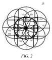
- FIG. 2 is a block diagram illustrating increased range for a wireless access point through the use of repeaters constructed in accordance with the principles of the present invention
- FIG. 3 is a block diagram of an exemplary wireless access point constructed in accordance with the principles of the present invention.
- FIG. 4 is a block diagram of an exemplary EAS device node constructed in accordance with the principles of the present invention.
- FIG. 5 is an exemplary RF packet frame structure constructed in accordance with the principles of the present invention.
- FIG. 6 is an exemplary UART packet frame structure constructed in accordance with the principles of the present invention.
- FIG. 7 is a control diagram illustrating an authentication process according to the principles of the present invention.
- FIG. 8 is a block diagram illustrating layered addressing in accordance with the principles of the present invention.
- FIG. 9 is more detailed block diagram of the exemplary EAS communication system of FIG. 1 constructed in accordance with the principles of the present invention.
- FIG. 10 is a block diagram of a parallel architecture design to simultaneously transfer RF channel data while receiving wired serial data in accordance with the principles of the present invention.
- FIG. 11 is a flow chart of an exemplary EAS sensor transmission completion predictor process according to the principles of the present invention.
- relational terms such as “first” and “second,” “top” and “bottom,” and the like, may be used solely to distinguish one entity or element from another entity or element without necessarily requiring or implying any physical or logical relationship or order between such entities or elements.
- One embodiment of the present invention advantageously provides a method and system for establishing wireless communication among EAS sensors and other EAS equipment.
- An embodiment of the present invention provides an architecture which expands upon a star topology by defining a method for layering repeaters on the star network and implementing a new communication scheme.
- the architecture provides a layered addressing approach in facilitating connectivity of devices to the network. This layered addressing approach allows existing wired networks to seamlessly connect to a wireless node in the wireless network.
- An embodiment of the present invention advantageously provides an effective means to seamlessly interface devices which use a serial interface and are not specifically designed for wireless networks to a wireless network.
- Bandwidth efficiency is obtained by maximizing the amount of information that is transferred in a RF channel and by minimizing the probability of breaking up information into multiple smaller payload transmissions which introduce additional framing bytes of overhead.
- the embodiments described below identify the sensors as EAS sensors, the principles of the present invention may also be applied to other types of sensor devices, including but not limited to intrusion sensors, temperature sensors, humidity sensors, etc.
- FIG. 1 an exemplary electronic article surveillance (“EAS”) communication network 10 for wirelessly connecting EAS sensors and equipment.
- Network 10 may include a wireless access point (“AP”) 12 which manages the network 10 and implements a poll-response protocol scheme to transfer information.
- Wireless device nodes 14 a , 14 b (two shown, referenced collectively as “wireless device node 14 ”) join the network 10 after being authenticated according to a join token.
- the join token is a value shared by all devices that form part of a particular network. Multiple networks can co-exist by using different join tokens.
- Repeaters 16 a , 16 b are used to extend the range of the access point 12 . Operation of the repeater 16 is discussed in greater detail below. It should be noted that network 10 may include any number of access points 12 , device nodes 14 and repeaters 16 .
- the exemplary network 10 illustrated in FIG. 1 includes two repeaters 16 a , 16 b deployed around an access point 12 .
- Repeaters 16 join a network 10 and retransmit RF communication packets according to a decay value. Once a repeater 16 receives a transmission, the repeater 16 re-plays the transmission if the decay value is not zero and decrements the decay count. A repeater 16 seeing a retransmission from another repeater 16 also replays the transmission if the decay count is not zero. Since a message is re-played, the bandwidth used by a transmission doubles each time a repeater 16 re-transmits a message.
- a repeater 16 will retransmit the same message more than once if a different repeater 16 re-transmits the message.
- a repeater 16 In one mode of operation, a repeater 16 only retransmits messages received from an access point 12 or wireless device node 14 . This mode of operation avoids the repeated transmission of the same message by a repeater 16 .
- the decay count can be set to 1 by the access point 12 or wireless device nodes 14 . This method allows for the addition of multiple repeaters 16 around an access point 12 and expansion of the network range. The coverage provided by this approach is sufficient for the majority of applications.
- FIG. 2 An alternative embodiment illustrating how the range of the access point 12 may be increased by a layer of repeaters 16 is shown in FIG. 2 .
- re-transmission control is introduced by tracking the address of the originating wireless node 14 and the message identification number used by the originating wireless node 14 . This control qualifies a message before being re-transmitted by a repeater 16 . Messages that are re-transmitted by a repeater 16 are stored in a tracking table. The tracking table is checked whenever a message is received from a repeater 16 . Transmission frames include a transmitting device type which allows the receiving device to determine if the message is from a wireless node device 14 , access point 12 or repeater 16 .
- Another device identifier may be a wireless tag. Repeaters 16 always repeat messages from any wireless node device 14 , with the exception that messages from repeater devices 16 are qualified against the tracking table before retransmission. When a new message ID is received from a device 46 , the tracking table is updated.
- a wireless access point 12 includes a communication interface 18 communicatively coupled to a controller 20 .
- the communication interface 18 includes at least one wired interface 22 and at least one wireless interface 24 coupled to an antenna 26 .
- the communication interface 18 transfers data packets between the wireless access point 12 , repeaters 16 and other devices within the communication network 10 using an exemplary radio frequency (“RF”) protocol defined below.
- RF radio frequency
- the communication interface 18 may include any number of communication ports.
- the controller 20 controls the processing of information and the operation of the wireless access point 12 to perform the functions described herein.
- the controller 20 is also coupled to a memory 28 .
- the memory 28 includes a data memory 30 and a program memory 32 .
- the data memory 30 includes three buffers associated with transferring data the network 10 and various other user data files (not shown).
- the buffers include a universal asynchronous receiver/transmitter (“UART”) buffer 34 , a serial data transfer buffer 36 and an RF data transfer buffer 38 .
- UART buffer 34 contains a single byte of data to be transmitted to or received through the wired interface 22 .
- a UART data structure is discussed below.
- the data memory 30 also includes a serial idle timer 40 , a serial idle short term moving average 42 and a serial idle trigger 44 .
- the serial idle timer 40 is a free-running counter which tracks the time elapsed between UART packet transmissions.
- the serial idle trigger 44 is a maximum idle value allowed before triggering an RF packet transmission.
- the serial idle short term moving average 42 is a series of samples of the actual serial idle time between UART packet transmissions and is used to adjust the serial idle trigger 44 as needed.
- the program memory 32 contains a UART control engine 46 , a serial control engine 48 , an RF control engine 50 and a predictor 52 .
- the UART control engine 46 directs the transfer of data to and from the UART buffer 34 .
- the serial control engine 48 directs the transfer of data to and from the serial data transfer buffer 36 and the RF control engine 50 directs the transfer of data to and from the RF data transfer buffer 38 .
- the predictor 52 determines when to transfer data and adaptively adjusts the serial idle trigger 44 appropriately.
- the predictor 52 determines when the idle time on the serial bus indicates that a sensor transmission has completed. By predicting the end of a transmission, the opportunity to gather the maximum number of bytes for a single RF transmission is increased. This approach maximizes the ratio of information data bytes to the framing and networking management bytes. Operation of the predictor 52 is discussed in greater detail below.
- each wireless access point 12 may include additional, optional structures (not shown) which may be needed to conduct other functions of the wireless access point 12 .
- a wireless device node 14 includes a communication interface 54 electrically coupled to a controller 56 .
- the communication interface 54 includes at least one wired interface, such as a UART or serial input/output (“I/O”) interface.
- the communication interface 54 transfers information between the device node 14 and at least one EAS sensor (not shown).
- the controller 56 controls the processing of information and the operation of the device node 14 to perform the functions described herein.
- the controller 56 is also electrically coupled to a transceiver 58 .
- the transceiver 60 transmits and receives data packets from the wireless access point 12 through at least one antenna 60 , in a manner known in the art.
- the antenna 60 may be, for example, a microstrip antenna coupled to the transceiver 60 using a balun 62 .
- the EAS communication network 10 implements a broadcast and a point-to-point messaging scheme between the access points 12 and the wireless device nodes 14 .
- the network 10 may use the exemplary RF framing structure 64 , i.e., a packet, shown in FIG. 5 .
- the RF packet fields include Preamble 66 , SYNC 68 , Length 70 , Destination Address (“DSTADDR”) 72 , Source Address (“SRCADDR”) 74 , Port 76 , Device Info 78 , Transaction ID (“TractID”) 80 , Network message command type (“nwkCMD”) 82 , Network message Identification (“nwkMsgID”) 84 , Application data (“App Payload”) 86 and Cyclic redundancy check (“CRC”) 88 fields.
- the preamble 66 and SYNC 68 fields are used for radio synchronization.
- the length field 70 contains the number of total bytes in the packet 64 .
- the Destination Address 72 and Source Address 74 fields may be 4-byte fields which contain the address of the destination device and the source device, respectively; however, the length of the field may vary.
- the Port field 76 is a 1-byte field containing encryption context in the highest two bits and the Application port number in the remaining six bits.
- the Device Info field 78 contains sender/receiver and platform capabilities and is discussed in greater detail below.
- the Transaction ID field 80 includes an identifier for the present message.
- the Network message command type 82 and Network message Identification 84 fields are used for upper network layer messaging and identification for transmission management.
- the nwkCMD 82 identifies the type of message being transmitted.
- nwkCMD field 82 value indicates to the device node 14 that this is an acknowledge transmission of an earlier package.
- the nwkMsgID 84 indicates which message is being acknowledged by the receiving node.
- the transmitting device node stops attempting to transmit the packet (after time out periods) because the packet has been received.
- a broadcast command has its own nwkCMD 82 , in this case the device node 12 may not acknowledge the transmission if the implementation is for the wired sensor device to initiate the return acknowledge action.
- download of firmware can have its own nwkCMD 82 .
- the remaining fields include the actual transmitted data, i.e., Application data 86 and a CRC 88 calculated based on all of the fields of the packet 64 except for the Preamble 66 and SYNC 68 fields.
- the UART packet 90 is used in transmitting data between the wireless access point 12 and other devices using the wired interface 22 .
- the UART packet 90 includes a start bit 92 , an 8-bit data payload 94 , a parity bit 96 and a stop bit 98 .
- an exemplary network authentication process is shown.
- the end device 100 Before an end device 100 , such as an EAS sensor, can participate in the wireless network 10 , the end device 100 must be authenticated.
- the end device 100 is generally hard-wired to a wireless device node 14 .
- the end device 100 connects to the network 10 after authentication.
- the authentication process begins when a device 100 wishing to join the network 10 issues a join message.
- the access point 12 responds to the join message to authenticate the device 100 to the network 10 .
- a link message is exchanged between the access point 12 and each wireless node device 14 in the network. Links occur in pairs and establish a point to point connection.
- the access point 12 has a link ID for each connection. This link ID is used as a handle by higher level software operations to communicate point-to-point between wireless nodes, e.g., between the access point 12 and wireless device nodes 14 .
- the device address can be configured on the device 100 or a random addressing scheme may be implemented to reduce the configuration burden.
- the wireless node 14 selects a random address for operating on the network.
- the random address can be selected in multiple ways. One method is the use of a loose tolerance R-C network.
- the R-C network is tied to an input comparator pin of the processor.
- the RC time constant is chosen to allow the processor time to power up and start a counter.
- the processor starts a counter at power up, which in itself is random, and the counter counts until the comparator input pin is triggered by the RC time constant.
- the value in the register is used as the wireless node address or is used to generate the address according to some formula.
- the random address selected by the device 100 is validated by the access point 12 at the time the wireless node 14 joins the network. If another wireless node 14 with the same address has already joined the network 10 , the access point 12 issues an address verification message to determine if that old device is still on the network 10 . The new device 100 trying to join does not respond to this address verification message. If the old device responds to the address verification, then access to the network 10 to the new device is denied and a duplicate address status returned. The new device 100 can be reset to produce a new random address to join the network 10 and the sequence repeats until the new device has a unique address. Alternatively, a software random number generator may be used to generate the initial address. It is also acceptable to have an incrementing counter and the counter value used to create the address. The count increments if the access point 12 does not accept the address.
- one embodiment of the present invention provides a method of broadcast and response that relies on the sub-layer (address) device to complete the message acknowledgment for broadcast messages while device responses to a broadcast message are acknowledged at the wireless network layer.
- Point-to-point messages between a wireless node 14 and the access point 12 are acknowledged at the wireless network layer.
- the sub-layer manages message time outs and the rebroadcast of unacknowledged broadcast messages.
- An access point 12 broadcasts messages (payloads) received from a wired connection.
- the access point 12 may also forward a message received from a wireless node 14 as a broadcast message, or the access point 12 may forward the message to a specific wireless network node 14 depending on the received message information.
- the access point 12 forwards a received wireless node message as a broadcast message, the access point 12 returns the information received from a device responding to the broadcast message back to the wireless node device 14 that requested the broadcast.
- a local device manager (“LDM”) 102 is wired to an access point 12 .
- the wireless nodes 14 are connected to general EAS devices 100 (one shown).
- This layered addressing approach assigns an address to the wireless node device 14 which is used when communicating on the wireless network 10 .
- Devices 100 that connect, through a wired serial interface (or serial/parallel PCB layout), to the wireless device node 14 implement a sub-layer addressing scheme. This sub-layer can work as its own independent communication network.
- Messages received by the wireless access point 12 from an LDM device 102 are transmitted by the access point 12 as wireless broadcast messages.
- Broadcast messages are received by a wireless device nodes 14 and the frame payload, which is discussed in further detail below, is sent to the device 100 via a wired connection, such as but not limited to, a connection defined according to the RS485 specification.
- a wired connection such as but not limited to, a connection defined according to the RS485 specification.
- devices 100 which have a matching address at the sub-address level will respond to the messages from the LDM 102 .
- the sub-layer device 100 will not acknowledge the broadcast message.
- the LDM 102 If the wired LDM 102 has not received an acknowledgement of the broadcast message within a predetermined length of time, the LDM 102 will resend the message to the access point 12 . Therefore, the responsibility of guaranteed delivery rests with the LDM 102 , not the wireless device nodes 12 and 14 , allowing the wireless device node 14 to be relatively simple and inexpensive, e.g., a wired-to-wireless adapter.
- the wireless node 14 uses a point-to-point transmission where the source and destination addresses of the wireless packet identify the source wireless device 12 and the destination access point 12 address.
- the payload of the wireless packet identifies the acknowledging source device 100 and destination wired device 102 .
- Receptions of point-to-point messages are acknowledged at the wireless network layer. Retries, time outs and message IDs are used in strengthening wireless network transmission robustness.
- the access point 12 transmits a frequency migration command that includes the new frequency indicator. After the command is issued, the access point 12 has the option of issuing a device node migration check command. After allowing time for migration, the access point 12 receives a confirmation from each device 100 . If a device 100 does not migrate, the access point 12 can return to the prior frequency and re-issues the command and/or requests status from the lagging device 100 . The access point 12 may return to the prior frequency periodically until all devices 100 have migrated. Exceptions are noted and included in the status of the access point 12 status.
- a ping may be sent by the access point 12 .
- a ping is defined as the frequency migration command, or an access point present signal (which can be transmitted periodically by the access point) or other signal indicating the presence of the access point.
- Wireless devices 14 not receiving a ping at the expected time automatically move to the next frequency and listen for a ping from the access point 12 . If a ping is not found the wireless device 14 will move to the next frequency and check for the ping command.
- An exemplary parallel architecture design is used to simultaneously transfer RF channel data while receiving wired serial data and vice versa.
- a trigger determines when data in a serial data buffer 36 is transferred to an RF data transfer buffer 38 . While the transfer is occurring between the serial control engine 48 and the RF control engine 50 , the UART buffer control 46 , in parallel, accepts incoming serial data packets into the UART buffer 34 . In other words, data buffers between the serial control engine 48 and the RF control engine 50 may be transferred while UART buffer 34 is accepting new data.
- the serial data buffer 36 transfers its data to the RF data transfer buffer 38
- both the serial control engine 48 and the RF control engine 50 continue to work in parallel.
- the RF control engine 50 packetizes and manages the RF transmission, while the serial control engine 48 accepts new serial data.
- recovered RF data is sent immediately to the serial interface after receiving a packet.
- information in the serial data buffer 36 is processed without decoding incoming bytes received in the packet payload to gain knowledge of transfer count or signaling information, such as Start/Stop indicators.
- the RF network 10 can indicate that a packet is a partial packet based on receiving the maximum number of bytes in the RF buffer 38 and serial idle not occurring at the transmitting device.
- the recovered RF data is held in the serial data transfer buffers 36 until the rest of the packet is received.
- a receive buffer capable of holding 256 bytes, received from a transmitting node may be used. The transfer should occur quicker than a UART buffer packet time.
- Packets are received and processed from the serial bus as follows.
- a trigger is defined by the serial idle trigger 44 and is associated with the time that it takes to transmit a serial bus packet.
- Sensor applications often transmit information in bursts. These bursts may contain delays in between packet bytes or may be tightly coupled in time.
- An embodiment of the present invention learns the idle time between byte transmissions for a serial application (device) in order to more efficiently manage the bandwidth of the RF channels.
- RF transmission rate RF radio chip first-in-first-out (“FIFO”) size
- serial transmission rate serial transmission rate
- idle time of the serial interface RF radio chips can have predefined FIFO buffer sizes. FIFO usage is determined by application and data management algorithms.
- the RF channel transfer rate should be higher than the serial interface transfer rate to decrease the amount of memory storage for serial data received and to provide buffer overflow robustness. This consideration is used to provide a seamless wireless connectivity to EAS devices.
- an exemplary operational flowchart is provided that describes steps performed by the predictor 52 for deciding when to end collecting data from a serial connection and begin an RF transmission, in accordance with the principles of the present invention.
- the RF channel baud rate should be higher than the serial baud rate, allowing for robustness in providing a seamless connectivity to devices on the serial bus, for illustrative purposes only, an exemplary transfer rate of 250 Kbaud is used on the RF channel and 38.4K on the serial interface.
- the predictor 52 tracks the time elapsed between serial byte packets using a free-running serial idle timer 40 , which may be implemented as a counter, to adjust the serial idle trigger value 44 that triggers an RF transmission.
- the maximum serial idle time for a trigger may be defined as an application parameter.
- the initial setting is associated with the RF buffer transmission time and may be a product of some factor, for example, to 0.5, 1, or some increment (e.g., 2, 2.5, etc.) times the time used to transmit the RF buffer.
- the serial idle trigger 44 is set to a time equivalent to one RF transmission; however, as the serial idle time trigger 44 of the predictor 52 is an adaptive parameter, the serial idle time trigger 44 is adjusted to optimize the performance of the network 10 . For example, the serial idle time trigger 44 of the predictor 52 is increased if the time lapse between bytes increases.
- the serial idle trigger 44 may be bounded by a maximum value of, for example, twice the RF transmission time. Larger maximum values may be implemented, if necessary, as required by the network design; however, the maximum trigger value should be set in reference to some known parameter, such as the RF transmission time. Generally, lapses between UART packets occurring greater than 2 milliseconds allow an RF transmission to take place seamlessly and create buffer space in the device.
- the predictor 52 determines when to initiate a buffer transfer from the serial data transfer buffer 36 to the RF data transfer buffer 38 and vice versa.
- the predictor 52 is generally in an idle state until it detects an interrupt trigger, which may be presented in the form of a serial data interrupt (step S 102 ).
- Triggers may include, for example, the serial transfer buffer 50 receiving the maximum number of bytes accepted by the RF buffer 52 or the time between serial bytes received exceeding the serial idle time trigger 44 .
- step S 104 data in the UART buffer 34 is transferred to the serial data buffer 36 (step S 104 ). If the amount of data in the serial data buffer 36 , e.g., ByteCnt, has not reached the predetermined RF data buffer 38 size, e.g., RFBuffSize (step S 106 ), then the trigger is most likely caused as a result of the free-running serial idle timer 40 , e.g., SerialIdleCnt, reaching the serial idle trigger 44 limit, e.g., IdleTriggerCnt. If the free-running serial idle timer 40 has reached the serial idle trigger 44 limit (step S 108 ), then the serial idle trigger 44 is updated (step S 110 ) in the following manner.
- the free-running serial idle timer 40 has reached the serial idle trigger 44 limit (step S 108 )
- the serial idle trigger 44 is updated (step S 110 ) in the following manner.
- the serial idle time trigger 44 is constructed from a serial idle short term moving average (“MA”) 42 and a long term predictor.
- a long term predictor (“LTP”) is weighted along with the MA in formulating the serial idle trigger 44 value.
- An initial LTP value may be based on a settable initial value. This value can be correlated to the time needed to transmit a RF buffer or the time needed to receive a given number of UART bytes, e.g., two.
- Equation 2 defines the filter operation in determining the long term predictor value.
- the LTP is used as input to the serial interface idle time trigger.
- the lpt Coeff and ma Coeff determine the weighting given to LTP and MA.
- a minimum idle constant, K is added to the LPT in obtaining the serial idle time trigger 44 .
- K accounts for the time in one serial packet transmission and provides a tolerance allow for minimal gaps in serial packet transmission.
- K is set to one or more serial packet times.
- T IS K +LTP.
- an RF transmission time of 2.3 mS (50 byte buffer+framing bits) corresponds to approximately 11 bytes transmitted on the serial interface.
- An embodiment of the MA 42 uses a value of one for N. However, the sample X N is taken as the largest time between serial byte packets in a given transmission. In this approach, the largest idle time between serial byte packets in a transmission is used to adapt the predictor 52 . The single input is selected as the largest gap between transmission before the serial trigger occurred or the RF buffer byte count was reached. This approach allows for a low computational algorithm and favors the larger gap value in serial packet transmission. The weighting of LTP and MA determines the rate of change in serial idle time.
- the trigger is caused by the serial data transfer buffer 36 being full.
- the RF data buffer size is associated with the physical buffer size of the radio chip. However the RF data buffer size may be adjusted for various reasons, such as, the locations of buffer bytes for use by control and messaging bytes. Locations may be unused to provide margin in case of overflow.
- the predictor then sets the X N term of the serial idle short term moving average 42 , e.g., RefSerialIdleCnt, to the largest SerialIdleCnt value seen since the last update (step S 120 ) and the predictor 52 returns to a wait for the next trigger (step S 102 ).
- Embodiments of the present invention may use this method for predicting optimal RF transmissions to allow an EAS sensor that is normally hard-wired to a control unit to be implemented as a wireless device.
- the EAS communication network may be established quickly and relatively inexpensively when compared with prior methods of wireless communication.
- the present invention can be realized in hardware, software, or a combination of hardware and software. Any kind of computing system, or other apparatus adapted for carrying out the methods described herein, is suited to perform the functions described herein.
- a typical combination of hardware and software could be a specialized computer system having one or more processing elements and a computer program stored on a storage medium that, when loaded and executed, controls the computer system such that it carries out the methods described herein.
- the present invention can also be embedded in a computer program product, which comprises all the features enabling the implementation of the methods described herein, and which, when loaded in a computing system is able to carry out these methods.
- Storage medium refers to any volatile or non-volatile storage device.
- Computer program or application in the present context means any expression, in any language, code or notation, of a set of instructions intended to cause a system having an information processing capability to perform a particular function either directly or after either or both of the following a) conversion to another language, code or notation; b) reproduction in a different material form.
Abstract
Description
MA=(X 1 +X 2 +X 3 + . . . +X N)/N, (1)
where X1 . . . XN are measured samples of the actual serial idle time. A long term predictor (“LTP”) is weighted along with the MA in formulating the serial
LTP=LTP*lpt Coeff+MA*ma coeff, (2)
where
lpt Coeff+ma Coeff=1. (3)
The LTP is used as input to the serial interface idle time trigger. The lpt Coeff and ma Coeff determine the weighting given to LTP and MA.
T IS =K+LTP. (4)
Claims (20)
Priority Applications (9)
| Application Number | Priority Date | Filing Date | Title |
|---|---|---|---|
| US12/477,480 US8274359B2 (en) | 2009-06-03 | 2009-06-03 | Wireless connectivity for sensors |
| CN201080024231.6A CN102460526B (en) | 2009-06-03 | 2010-04-15 | Wireless connectivity point for EAS network and related method |
| KR1020127000181A KR101620519B1 (en) | 2009-06-03 | 2010-04-15 | Wireless connectivity for sensors |
| ES10718747.8T ES2627434T3 (en) | 2009-06-03 | 2010-04-15 | Wireless connectivity for sensors |
| PCT/US2010/001135 WO2010141049A1 (en) | 2009-06-03 | 2010-04-15 | Wireless connectivity for sensors |
| AU2010254606A AU2010254606B2 (en) | 2009-06-03 | 2010-04-15 | Wireless connectivity for sensors |
| EP10718747.8A EP2438581B1 (en) | 2009-06-03 | 2010-04-15 | Wireless connectivity for sensors |
| CA2764239A CA2764239C (en) | 2009-06-03 | 2010-04-15 | Wireless connectivity for sensors |
| HK12107837.8A HK1167201A1 (en) | 2009-06-03 | 2012-08-09 | Wireless access point used in an eas network and corresponding method eas |
Applications Claiming Priority (1)
| Application Number | Priority Date | Filing Date | Title |
|---|---|---|---|
| US12/477,480 US8274359B2 (en) | 2009-06-03 | 2009-06-03 | Wireless connectivity for sensors |
Publications (2)
| Publication Number | Publication Date |
|---|---|
| US20100308956A1 US20100308956A1 (en) | 2010-12-09 |
| US8274359B2 true US8274359B2 (en) | 2012-09-25 |
Family
ID=42357347
Family Applications (1)
| Application Number | Title | Priority Date | Filing Date |
|---|---|---|---|
| US12/477,480 Active 2030-12-27 US8274359B2 (en) | 2009-06-03 | 2009-06-03 | Wireless connectivity for sensors |
Country Status (9)
| Country | Link |
|---|---|
| US (1) | US8274359B2 (en) |
| EP (1) | EP2438581B1 (en) |
| KR (1) | KR101620519B1 (en) |
| CN (1) | CN102460526B (en) |
| AU (1) | AU2010254606B2 (en) |
| CA (1) | CA2764239C (en) |
| ES (1) | ES2627434T3 (en) |
| HK (1) | HK1167201A1 (en) |
| WO (1) | WO2010141049A1 (en) |
Cited By (1)
| Publication number | Priority date | Publication date | Assignee | Title |
|---|---|---|---|---|
| US10841230B1 (en) * | 2019-08-01 | 2020-11-17 | Vulcan Technologies Shanghai Co., Ltd. | Intelligent controller and sensor network bus, system and method |
Families Citing this family (3)
| Publication number | Priority date | Publication date | Assignee | Title |
|---|---|---|---|---|
| US20140300477A1 (en) | 2012-09-25 | 2014-10-09 | Woodstream Corporation | Wireless notification systems and methods for electronic rodent traps |
| US20180096581A1 (en) * | 2016-09-30 | 2018-04-05 | Woodstream Corporation | Long range wireless notification system and method for electronic rodent traps |
| US11278020B2 (en) | 2018-02-12 | 2022-03-22 | Woodstream Corporation | Electronic rodent traps with remote monitoring capability |
Citations (6)
| Publication number | Priority date | Publication date | Assignee | Title |
|---|---|---|---|---|
| US4745599A (en) * | 1987-01-05 | 1988-05-17 | General Electric Company | Random access communication system with contention scheduling of subpacketized data transmissions and scheduled retransmission of unsuccessful subpackets |
| US20020158762A1 (en) | 2001-04-25 | 2002-10-31 | Thang Nguyen | Security apparatus for electronic article surveillance tag |
| US20050270155A1 (en) | 2004-06-02 | 2005-12-08 | Sayegh Adel O | Integrated theft deterrent device |
| US7005985B1 (en) * | 1999-07-20 | 2006-02-28 | Axcess, Inc. | Radio frequency identification system and method |
| US20060164213A1 (en) * | 2005-01-26 | 2006-07-27 | Battelle Memorial Institute | Method for autonomous establishment and utilization of an active-RF tag network |
| US20060170550A1 (en) | 2005-01-14 | 2006-08-03 | Alpha Security Products, Inc. | Cable alarm security device |
Family Cites Families (4)
| Publication number | Priority date | Publication date | Assignee | Title |
|---|---|---|---|---|
| US7567176B2 (en) * | 2004-05-17 | 2009-07-28 | Randy Stephens | Location-based anti-theft and security system and method |
| US7589616B2 (en) * | 2005-01-20 | 2009-09-15 | Avaya Inc. | Mobile devices including RFID tag readers |
| US7755485B2 (en) * | 2005-03-08 | 2010-07-13 | Inpoint Systems, Inc. | System and method for electronic article surveillance |
| US20080198016A1 (en) * | 2007-02-20 | 2008-08-21 | Daniel Lawrence | Rfid system |
-
2009
- 2009-06-03 US US12/477,480 patent/US8274359B2/en active Active
-
2010
- 2010-04-15 CA CA2764239A patent/CA2764239C/en not_active Expired - Fee Related
- 2010-04-15 AU AU2010254606A patent/AU2010254606B2/en not_active Ceased
- 2010-04-15 WO PCT/US2010/001135 patent/WO2010141049A1/en active Application Filing
- 2010-04-15 KR KR1020127000181A patent/KR101620519B1/en active IP Right Grant
- 2010-04-15 ES ES10718747.8T patent/ES2627434T3/en active Active
- 2010-04-15 CN CN201080024231.6A patent/CN102460526B/en not_active Expired - Fee Related
- 2010-04-15 EP EP10718747.8A patent/EP2438581B1/en not_active Not-in-force
-
2012
- 2012-08-09 HK HK12107837.8A patent/HK1167201A1/en not_active IP Right Cessation
Patent Citations (6)
| Publication number | Priority date | Publication date | Assignee | Title |
|---|---|---|---|---|
| US4745599A (en) * | 1987-01-05 | 1988-05-17 | General Electric Company | Random access communication system with contention scheduling of subpacketized data transmissions and scheduled retransmission of unsuccessful subpackets |
| US7005985B1 (en) * | 1999-07-20 | 2006-02-28 | Axcess, Inc. | Radio frequency identification system and method |
| US20020158762A1 (en) | 2001-04-25 | 2002-10-31 | Thang Nguyen | Security apparatus for electronic article surveillance tag |
| US20050270155A1 (en) | 2004-06-02 | 2005-12-08 | Sayegh Adel O | Integrated theft deterrent device |
| US20060170550A1 (en) | 2005-01-14 | 2006-08-03 | Alpha Security Products, Inc. | Cable alarm security device |
| US20060164213A1 (en) * | 2005-01-26 | 2006-07-27 | Battelle Memorial Institute | Method for autonomous establishment and utilization of an active-RF tag network |
Non-Patent Citations (1)
| Title |
|---|
| International Search Report and Written Opinion dated Oct. 14, 2010 for International Application No. PCT/US2010/001153, International Filing Date: Apr. 17, 2010 consisting of 14-pages. |
Cited By (1)
| Publication number | Priority date | Publication date | Assignee | Title |
|---|---|---|---|---|
| US10841230B1 (en) * | 2019-08-01 | 2020-11-17 | Vulcan Technologies Shanghai Co., Ltd. | Intelligent controller and sensor network bus, system and method |
Also Published As
| Publication number | Publication date |
|---|---|
| KR101620519B1 (en) | 2016-05-12 |
| WO2010141049A1 (en) | 2010-12-09 |
| HK1167201A1 (en) | 2012-11-23 |
| CN102460526A (en) | 2012-05-16 |
| CN102460526B (en) | 2014-10-22 |
| EP2438581A1 (en) | 2012-04-11 |
| ES2627434T3 (en) | 2017-07-28 |
| KR20120024935A (en) | 2012-03-14 |
| US20100308956A1 (en) | 2010-12-09 |
| AU2010254606A1 (en) | 2012-01-12 |
| AU2010254606B2 (en) | 2015-03-26 |
| CA2764239A1 (en) | 2010-12-09 |
| CA2764239C (en) | 2017-03-14 |
| EP2438581B1 (en) | 2017-03-08 |
Similar Documents
| Publication | Publication Date | Title |
|---|---|---|
| US11330469B2 (en) | Increasing access point throughput by exceeding A-MPDU buffer size limitation in a 802.11 compliant station | |
| TWI242946B (en) | Wireless packet communication apparatus and method | |
| US8284669B2 (en) | Data acknowledgement apparatus and method | |
| EP2760143B1 (en) | Apparatus for transmitting and receiving data in NFC | |
| KR101668768B1 (en) | Systems and methods for packet relaying | |
| RU2670605C9 (en) | System and method for indicating type of response frame | |
| US20070115821A1 (en) | Method for transmitting wireless data using piggyback | |
| US20230319526A1 (en) | Wireless sensor system, wireless terminal device, communication control method and communication control program | |
| WO2006048969A1 (en) | Transmitter apparatus | |
| US8588068B2 (en) | Communication terminal and communication method | |
| CA2764239C (en) | Wireless connectivity for sensors | |
| Kumar et al. | Performant {TCP} for {Low-Power} wireless networks | |
| CN108886713B (en) | Data transmission method, data receiving equipment and data sending equipment | |
| CN113826331A (en) | Apparatus, system, and method for selecting wireless device antennas for communication | |
| KR20160049919A (en) | Method for managing coordinator in wireless sensor network for minimizing sensor data losses | |
| EP1505759B1 (en) | Method and device for transmitting/receiving data using acknowledged transport layer protocols | |
| US10425371B2 (en) | Method for fragmented messaging between network devices | |
| JP2021090185A (en) | Data transmission method and communication system | |
| CN112806054A (en) | Communicating in a wireless network | |
| Gnawali et al. | Sensor networks architectures and protocols | |
| JP2003283472A (en) | Data transfer control method | |
| Raitahila | Congestion Control Algorithms for the Constrained Application Protocol (CoAP) | |
| JP2006165758A (en) | Wireless lan device and wireless lan transfer control method | |
| Burgi et al. | Performance Optimization for TCP-based Wireless Sensor Networks |
Legal Events
| Date | Code | Title | Description |
|---|---|---|---|
| AS | Assignment |
Owner name: SENSORMATIC ELECTRONICS CORPORATION, FLORIDA Free format text: ASSIGNMENT OF ASSIGNORS INTEREST;ASSIGNORS:ALICOT, JORGE F.;RELIHAN, TIMOTHY J.;REEL/FRAME:022774/0825 Effective date: 20090602 |
|
| AS | Assignment |
Owner name: SENSORMATIC ELECTRONICS, LLC, FLORIDA Free format text: MERGER;ASSIGNOR:SENSORMATIC ELECTRONICS CORPORATION;REEL/FRAME:024213/0049 Effective date: 20090922 |
|
| STCF | Information on status: patent grant |
Free format text: PATENTED CASE |
|
| AS | Assignment |
Owner name: ADT SERVICES GMBH, SWITZERLAND Free format text: ASSIGNMENT OF ASSIGNORS INTEREST;ASSIGNOR:SENSORMATIC ELECTRONICS, LLC;REEL/FRAME:029894/0856 Effective date: 20130214 |
|
| AS | Assignment |
Owner name: TYCO FIRE & SECURITY GMBH, SWITZERLAND Free format text: MERGER;ASSIGNOR:ADT SERVICES GMBH;REEL/FRAME:030290/0731 Effective date: 20130326 |
|
| FPAY | Fee payment |
Year of fee payment: 4 |
|
| AS | Assignment |
Owner name: SENSORMATIC ELECTRONICS, LLC, FLORIDA Free format text: ASSIGNMENT OF ASSIGNORS INTEREST;ASSIGNOR:TYCO FIRE & SECURITY GMBH;REEL/FRAME:047182/0674 Effective date: 20180927 |
|
| AS | Assignment |
Owner name: SENSORMATIC ELECTRONICS, LLC, FLORIDA Free format text: ASSIGNMENT OF ASSIGNORS INTEREST;ASSIGNOR:TYCO FIRE & SECURITY GMBH;REEL/FRAME:047188/0715 Effective date: 20180927 |
|
| MAFP | Maintenance fee payment |
Free format text: PAYMENT OF MAINTENANCE FEE, 8TH YEAR, LARGE ENTITY (ORIGINAL EVENT CODE: M1552); ENTITY STATUS OF PATENT OWNER: LARGE ENTITY Year of fee payment: 8 |
|
| MAFP | Maintenance fee payment |
Free format text: PAYMENT OF MAINTENANCE FEE, 12TH YEAR, LARGE ENTITY (ORIGINAL EVENT CODE: M1553); ENTITY STATUS OF PATENT OWNER: LARGE ENTITY Year of fee payment: 12 |