US8259794B2 - Method and system for encoding order and frame type selection optimization - Google Patents
Method and system for encoding order and frame type selection optimization Download PDFInfo
- Publication number
- US8259794B2 US8259794B2 US12/199,741 US19974108A US8259794B2 US 8259794 B2 US8259794 B2 US 8259794B2 US 19974108 A US19974108 A US 19974108A US 8259794 B2 US8259794 B2 US 8259794B2
- Authority
- US
- United States
- Prior art keywords
- sequence
- frame
- encoder
- dec
- enc
- Prior art date
- Legal status (The legal status is an assumption and is not a legal conclusion. Google has not performed a legal analysis and makes no representation as to the accuracy of the status listed.)
- Expired - Fee Related, expires
Links
Images

Classifications
-
- H—ELECTRICITY
- H04—ELECTRIC COMMUNICATION TECHNIQUE
- H04N—PICTORIAL COMMUNICATION, e.g. TELEVISION
- H04N19/00—Methods or arrangements for coding, decoding, compressing or decompressing digital video signals
- H04N19/10—Methods or arrangements for coding, decoding, compressing or decompressing digital video signals using adaptive coding
- H04N19/189—Methods or arrangements for coding, decoding, compressing or decompressing digital video signals using adaptive coding characterised by the adaptation method, adaptation tool or adaptation type used for the adaptive coding
- H04N19/192—Methods or arrangements for coding, decoding, compressing or decompressing digital video signals using adaptive coding characterised by the adaptation method, adaptation tool or adaptation type used for the adaptive coding the adaptation method, adaptation tool or adaptation type being iterative or recursive
-
- H—ELECTRICITY
- H04—ELECTRIC COMMUNICATION TECHNIQUE
- H04N—PICTORIAL COMMUNICATION, e.g. TELEVISION
- H04N19/00—Methods or arrangements for coding, decoding, compressing or decompressing digital video signals
- H04N19/10—Methods or arrangements for coding, decoding, compressing or decompressing digital video signals using adaptive coding
- H04N19/102—Methods or arrangements for coding, decoding, compressing or decompressing digital video signals using adaptive coding characterised by the element, parameter or selection affected or controlled by the adaptive coding
- H04N19/103—Selection of coding mode or of prediction mode
- H04N19/109—Selection of coding mode or of prediction mode among a plurality of temporal predictive coding modes
-
- H—ELECTRICITY
- H04—ELECTRIC COMMUNICATION TECHNIQUE
- H04N—PICTORIAL COMMUNICATION, e.g. TELEVISION
- H04N19/00—Methods or arrangements for coding, decoding, compressing or decompressing digital video signals
- H04N19/10—Methods or arrangements for coding, decoding, compressing or decompressing digital video signals using adaptive coding
- H04N19/102—Methods or arrangements for coding, decoding, compressing or decompressing digital video signals using adaptive coding characterised by the element, parameter or selection affected or controlled by the adaptive coding
- H04N19/115—Selection of the code volume for a coding unit prior to coding
-
- H—ELECTRICITY
- H04—ELECTRIC COMMUNICATION TECHNIQUE
- H04N—PICTORIAL COMMUNICATION, e.g. TELEVISION
- H04N19/00—Methods or arrangements for coding, decoding, compressing or decompressing digital video signals
- H04N19/10—Methods or arrangements for coding, decoding, compressing or decompressing digital video signals using adaptive coding
- H04N19/134—Methods or arrangements for coding, decoding, compressing or decompressing digital video signals using adaptive coding characterised by the element, parameter or criterion affecting or controlling the adaptive coding
- H04N19/146—Data rate or code amount at the encoder output
- H04N19/147—Data rate or code amount at the encoder output according to rate distortion criteria
-
- H—ELECTRICITY
- H04—ELECTRIC COMMUNICATION TECHNIQUE
- H04N—PICTORIAL COMMUNICATION, e.g. TELEVISION
- H04N19/00—Methods or arrangements for coding, decoding, compressing or decompressing digital video signals
- H04N19/10—Methods or arrangements for coding, decoding, compressing or decompressing digital video signals using adaptive coding
- H04N19/134—Methods or arrangements for coding, decoding, compressing or decompressing digital video signals using adaptive coding characterised by the element, parameter or criterion affecting or controlling the adaptive coding
- H04N19/146—Data rate or code amount at the encoder output
- H04N19/149—Data rate or code amount at the encoder output by estimating the code amount by means of a model, e.g. mathematical model or statistical model
-
- H—ELECTRICITY
- H04—ELECTRIC COMMUNICATION TECHNIQUE
- H04N—PICTORIAL COMMUNICATION, e.g. TELEVISION
- H04N19/00—Methods or arrangements for coding, decoding, compressing or decompressing digital video signals
- H04N19/10—Methods or arrangements for coding, decoding, compressing or decompressing digital video signals using adaptive coding
- H04N19/134—Methods or arrangements for coding, decoding, compressing or decompressing digital video signals using adaptive coding characterised by the element, parameter or criterion affecting or controlling the adaptive coding
- H04N19/154—Measured or subjectively estimated visual quality after decoding, e.g. measurement of distortion
-
- H—ELECTRICITY
- H04—ELECTRIC COMMUNICATION TECHNIQUE
- H04N—PICTORIAL COMMUNICATION, e.g. TELEVISION
- H04N19/00—Methods or arrangements for coding, decoding, compressing or decompressing digital video signals
- H04N19/10—Methods or arrangements for coding, decoding, compressing or decompressing digital video signals using adaptive coding
- H04N19/134—Methods or arrangements for coding, decoding, compressing or decompressing digital video signals using adaptive coding characterised by the element, parameter or criterion affecting or controlling the adaptive coding
- H04N19/157—Assigned coding mode, i.e. the coding mode being predefined or preselected to be further used for selection of another element or parameter
-
- H—ELECTRICITY
- H04—ELECTRIC COMMUNICATION TECHNIQUE
- H04N—PICTORIAL COMMUNICATION, e.g. TELEVISION
- H04N19/00—Methods or arrangements for coding, decoding, compressing or decompressing digital video signals
- H04N19/10—Methods or arrangements for coding, decoding, compressing or decompressing digital video signals using adaptive coding
- H04N19/134—Methods or arrangements for coding, decoding, compressing or decompressing digital video signals using adaptive coding characterised by the element, parameter or criterion affecting or controlling the adaptive coding
- H04N19/162—User input
-
- H—ELECTRICITY
- H04—ELECTRIC COMMUNICATION TECHNIQUE
- H04N—PICTORIAL COMMUNICATION, e.g. TELEVISION
- H04N19/00—Methods or arrangements for coding, decoding, compressing or decompressing digital video signals
- H04N19/10—Methods or arrangements for coding, decoding, compressing or decompressing digital video signals using adaptive coding
- H04N19/169—Methods or arrangements for coding, decoding, compressing or decompressing digital video signals using adaptive coding characterised by the coding unit, i.e. the structural portion or semantic portion of the video signal being the object or the subject of the adaptive coding
- H04N19/17—Methods or arrangements for coding, decoding, compressing or decompressing digital video signals using adaptive coding characterised by the coding unit, i.e. the structural portion or semantic portion of the video signal being the object or the subject of the adaptive coding the unit being an image region, e.g. an object
- H04N19/172—Methods or arrangements for coding, decoding, compressing or decompressing digital video signals using adaptive coding characterised by the coding unit, i.e. the structural portion or semantic portion of the video signal being the object or the subject of the adaptive coding the unit being an image region, e.g. an object the region being a picture, frame or field
-
- H—ELECTRICITY
- H04—ELECTRIC COMMUNICATION TECHNIQUE
- H04N—PICTORIAL COMMUNICATION, e.g. TELEVISION
- H04N19/00—Methods or arrangements for coding, decoding, compressing or decompressing digital video signals
- H04N19/10—Methods or arrangements for coding, decoding, compressing or decompressing digital video signals using adaptive coding
- H04N19/169—Methods or arrangements for coding, decoding, compressing or decompressing digital video signals using adaptive coding characterised by the coding unit, i.e. the structural portion or semantic portion of the video signal being the object or the subject of the adaptive coding
- H04N19/179—Methods or arrangements for coding, decoding, compressing or decompressing digital video signals using adaptive coding characterised by the coding unit, i.e. the structural portion or semantic portion of the video signal being the object or the subject of the adaptive coding the unit being a scene or a shot
Definitions
- the present invention relates to the field of encoder control more specifically, the present invention relates to frame encoding decision for video sequence to achieve a minimum sequence cost within a sequence resource budget.
- Video compression takes advantage of these redundancies, with the intention to reduce the size of the video data while maintaining the quality as much as possible. Such compression is referred to as lossy (as opposed to lossless), since the original data cannot be recovered exactly.
- Most modern codecs take advantage of correlation among video frames and transmit the differences between a current frame and a predicted frame compactly represented by prediction parameters.
- the predicted frame is usually similar to the original one.
- the residual information i.e., prediction error
- the error signal usually is much smaller than the original signal and can be compactly represented using spatial transform, such as the discrete cosine transform (DCT) with subsequent quantization of the transform coefficients.
- DCT discrete cosine transform
- the quantized coefficients and the prediction parameters are entropy-encoded to reduce furthermore their redundancy.
- Inter-prediction exploits the temporal redundancy by using temporal prediction. Due to high level similarity among consecutive frames, temporal prediction can largely reduce the information required to present the video data. The efficiency of temporal prediction can be further improved by taking into account the object motion in the video sequence.
- the motion parameters associated with temporal prediction are transmitted to the decoder for reconstructing the temporal prediction. This type of prediction is used in MPEG-like codecs.
- the process of producing intra-prediction is called motion estimation. Typically, it is performed in a block-wise manner, when many modern codec support motion estimation with blocks of adaptive size.
- intra-prediction takes advantage of spatial redundancy and predicts portions of a frame (blocks) from neighbor blocks within the same frame.
- Such prediction is usually aware of spatial structures that may occur in a frame, namely smooth regions and edges.
- larger block size is more coding efficient for smooth areas and smaller block size is more coding efficient for areas with more texture variations.
- the prediction based on neighboring blocks can improve coding efficiency and a directional prediction can even further improve the efficiency.
- AVC H.264 Advances Video Codec
- the actual reduction in the amount of transmitted information is performed in the transmission of the residual.
- the residual frame is divided into blocks, each of which undergoes a DCT-like transform.
- the transform coefficients undergo quantization, usually performed by scaling and rounding. Quantization allows represent the coefficients by using less precision, thus reducing the amount of information required.
- Quantized transform coefficients are transmitted using entropy coding. This type of coding exploits the statistical characteristics of the underlying data.
- Y is the luminance component (luma) and Cb and Cr are chrominance components (chroma) of the color video.
- the chroma is typically down-sampled to half frame size in each direction because human eyes are less sensitive to the chroma signals and such format is referred to as the 4:2:0 format.
- the performance of a lossy video codec is measured as the tradeoff between the amount of bits required to describe the data and the distortion introduced by the compression, referred to as the rate-distortion (RD) curve.
- RD rate-distortion
- MSE mean squared error
- PSNR peak signal-to-noise ratio
- p 10 ⁇ log 10 ( y max 2 d ) ( 1 )
- d is the MSE
- y max is the maximum allowed value of the luma pixels, typically 255 if the luma data has an 8-bit precision and is represented in the range 0, . . . , 255.
- the H.264 AVC is one of the most recent standards in video compression, offering significantly better compression rate and quality compared to the previous MPEG-2 and MPEG-4 standards and targeted to high definition (HD) content.
- H.264 delivers the same quality as MPEG-2 at a third to half the data rate.
- a frame undergoing encoding is divided into non-overlapping macroblocks, each containing 16 ⁇ 16 luma pixels and 8 ⁇ 8 chroma pixels.
- macroblocks are arranged into slices, where a slice is a continuous raster scan of macroblocks. Each slice can be encoded independently of the other.
- Main slice types are P and I.
- An I slice may contain only I macroblocks; a P slice may contain P or I macroblocks.
- the macroblock type determines the way it is predicted.
- P refers to inter-predicted macroblocks; such macroblocks are subdivided into smaller blocks.
- I refers to intra-predicted macroblocks; such macroblocks are divided into 4 ⁇ 4 blocks (the luma component is divided into 16 blocks; each chroma component is divided into 4 blocks).
- I mode intra-prediction
- the prediction macroblock is formed from pixels in the neighbor blocks in the current slice that have been previously encoded, decoded and reconstructed, prior to applying the in-loop deblocking filter.
- the reconstructed macroblock is formed by imitating the decoder operation in the encoder loop.
- P mode inter-prediction
- the prediction macroblock is formed by motion compensation from reference frames.
- the prediction macroblock is subtracted from the current macroblock. The error undergoes transform, quantization and entropy coding.
- the best prediction mode is selected (i.e., the choice between an I or a P macroblock, the motion vectors in case of a P macroblock and the prediction mode in case of an I macroblock).
- the encoded residual for the macroblock in the selected best mode is sent to the bitstream.
- IDR instantaneous data refresh
- the operating point on the RD curve is controlled by the quantization parameter, determining the “aggressiveness” of the residual quantization and the resulting distortion.
- the quantization parameter is an integer in the range 0, . . . , 51, denoted here by q′.
- the quantization step doubles for every increment of 6 in q′. Sometimes, it is more convenient to use the quantization step rather than the quantization parameter, computed according to
- optimal resource allocation for a video sequence requires encoding the sequence with different sets of parameters and selecting one achieving the best result.
- Suboptimal resource allocation approaches usually try to model some typical behavior of the encoder as function of the encoding parameters. If the model has an analytical expression which can be efficiently computed, the optimization problem can be practically solved using mathematical optimization. However, since the model is only an approximate behavior of the encoder, the parameters selected using it may be suboptimal.
- the main difference between existing encoders is the decision process carried out by the bitrate controller that produces the encoder control parameters. Usually, the encoder parameters are selected in a way to achieve the best tradeoff between video quality and bitrate of the produced stream. Controllers of this type are referred to as RDO.
- Parameters controlled by the bitrate controller typically include: frame type and reference frame or frames if the frame is a P-frame on the sequence level, and macroblock type and quantization parameter for each macroblock on the frame level. For this reason, it is natural and common to distinguish between two levels of bitrate control: sequence- and frame-level.
- sequence-level controller is usually responsible for the frame type selection and allocation of the bit budget for the frame, and the frame-level controller is responsible for selection of the quantization parameter for each macroblock within the frame.
- the sequence level control is very limited.
- the frame type of a frame in a sequence is usually based on its order in a GOP according to a pre-determined pattern.
- the IBBPBBP . . . pattern is often used in MPEG standard where B is a bi-directional predicted frame.
- the GOP may be formed by partitioning the sequence into GOP of fixed size.
- the bit rate allocated to each frame usually is based on a rate control strategy.
- Such resource allocation for sequence encoding only exercises limited resource allocation and there is more room to improve. Based on the discussion presented here, there is a need for an optimal resource allocation for video sequence as well as for video frame.
- the current invention addresses the resource allocation for video sequence.
- the present invention provides an optimal resource allocation for video sequence to achieve the best possible quality within the sequence resource budget.
- the encoder provides as the output an action sequence of encoder parameters by selecting the frame type, quantization scale, and encoding complexity of picture to produce an encoded version of the sequence to achieve a minimum sequence cost within the sequence resource budget. Due to the high computational complexity of calculating the resource budget and video quality by actually performing the encoding process, the resource budget and the video quality are all estimated based on respective models.
- the resource budget used in this invention includes bit rate and encoding time.
- the optimal encoding process by selecting all possible combinations of frame type for individual frames of the sequence would require extremely high complexity if exhaustive search is used.
- the current invention uses a branch and bound algorithm to simplify the search procedure for an optimal decision on frame type of the sequence.
- FIG. 1 a shows a block diagram of the optimal resource allocation for video content.
- FIG. 1 b shows a general optimal resource allocation process.
- FIG. 2 a Example of buffer model: raw frame buffer.
- FIG. 2 b Example of buffer model: encoder bit buffer.
- FIG. 2 c Example of buffer model: decoder bit buffer.
- FIG. 3 Sequence-level controller flow diagram.
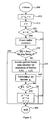
- FIG. 4 Flow diagram of branch and bound frame type decision algorithm.
- FIG. 5 Flow diagram of encoding order optimization
- the invention is directed to a system and method of encoding video sequence, that generally includes providing as the input a video sequence containing pictures as the input, a resource budget for the sequence, and a sequence cost function.
- the output is an action sequence of encoder parameters configured to produce an encoded version of the sequence to achieve a minimum sequence cost within the sequence resource budget.
- the resource allocation and control mechanism are generic and in principle can be used with any MPEG-type encoder or a similar mechanism.
- the underlying encoding pipeline implements the H.264 AVC encoder, with independent slice encoders working simultaneously. Such an implementation is currently typical of real-time hardware encoders.
- FIG. 1 A system-level block diagram of exemplary controllers configured according to the invention is shown in FIG. 1 .
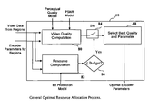
- Optimal Resource Allocation System illustrated as an Optimal Resource Allocation System is shown in FIG. 1 a , where a video content and resource/quality constraints are inputs to the system.
- the video content may be a video sequence, a video frame, a video field, or a partial frame.
- the video content is fed to Perceptual Quality Model 20 and Visual Clues Computation 40 .
- Perceptual Quality Model derives the parameters of the perceptual quality model based on the input video content.
- the Visual Clues Computation also derives the visual clues based on input video content.
- the information from Perceptual Quality Model and the information from the Visual Clues Computation are used to guide partitioning the input video content.
- the partitioning is based on a unit smaller than the input video content, such as a macroblock, macroblock pair, or block.
- the partitioning is performed by the Regions Partitioning 30 .
- the smaller unit for the partitioning is named sub-frame.
- the information from the Visual Clues Computation is used by both the Bit Production Model 50 and PSNR Model 60 . Both the Bit Production Model and the PSNR Model are useful for the encoder to evaluate the performance (bit rate and PSNR) without actually going through the computationally heavy encoding process. While the Bit Production is used as a measure of resource, any other resource measurement such as processing time can be used. Similarly, other quality model such as distortion can be used.
- the Optimal Resource Allocation 10 then exercises optimal resource allocation among the regions using the Bit Production Model, PSNR Model, and Perceptual Quality Model.
- the Video Quality Computation 80 block estimates the video quality of the video data of regions for the set of given encoder parameters instead of actually compress the video data using encoder parameters.
- the particular video quality computation in this exemplary case is PSNR shaping.
- the quality estimation is based on the perceptual quality model and PSNR model.
- the Resource Computation 82 block estimates the resource consumed for the given set of encoder parameters instead of actually compressing the video data.
- the bit production model is used to estimate the resource consumed.
- the estimated resource is compared in the compare process “ ⁇ Budget?” block 86 . If the result is true, the Switch 84 will close to allow the corresponding estimated quality computation pass to the Select Best Quality and Parameters block 88 .
- the Select Best Quality and Parameters block will compare all the video quality results entering the block and will select the best quality value and output the corresponding encoder parameters.
- the system consists of the sequence-level controller, which is responsible for frame type and reference selection and allocation of the bit budget and initial quantization parameter for the currently encoded frame.
- the frame-level sequence controller allocates the resources on sub-frame level, in order to utilize the total frame bit budget and achieve the highest perceptual visual quality.
- a perceptual quality model and a PSNR shaping mechanism are employed. Both controllers are based on the encoder model, which predicts the behavior of the encoder given a set of encoding parameters.
- the model utilizes visual clues, a set of descriptors of video data.
- the main focuses of the current invention are the encoder models and the sequence-level controller.
- the most important features of the sequence-level controller include:
- encoder model is to estimate the amount of resources used by the encoder without resorting to the expensive process of encoding itself. Specifically, the amount of bits produced by the encoder, the distortion as the result of encoding and the time complexity of the encoding process are predicted according to the encoder model.
- the encoder model is disclosed in U.S. patent application Ser. No. 12/040,788, filed Feb. 29, 2008.
- ⁇ circumflex over (x) ⁇ i is a macroblock-wise predictor
- ⁇ i are the encoding parameters
- z i are the visual clues in macroblock i
- N MB is the number of macroblocks in the frame
- K is some normalization factor.
- the amount of bits produced is proportional to the quantization step q i ⁇ 1 and to the macroblock complexity z i .
- texture in I-frames
- motion complexity in P-frames
- the luma PSNR is used as an objective distortion criterion.
- the PSNR is inversely proportional to the quantization parameter q i ⁇ 1 and to the macroblock complexity z i (texture complexity is used for both P- and I-frames).
- ⁇ circumflex over (p) ⁇ i ( q i ,z i ) ⁇ 1 ⁇ 2 z i ⁇ 3 q′ i (6)
- ⁇ 1 , ⁇ 2 , ⁇ 3 ⁇ 0 are the model parameters obtained by training.
- the sequence-level controller may decide to drop a frame.
- the decoder delays the previous frame for a longer duration, equal to the duration of the previous and current (dropped frame).
- the distortion due to the drop is computed as the average PSNR between a downsampled (16 times in each axis) version the dropped frame and the previous frame.
- the average PSNR is computed by first calculating the average MSE and then converting it into logarithmic scale (rather than averaging the PSNR values directly). For example, dropping a frame at the beginning of a new shot would result in a low PSNR, while dropping a frame in a sequence of frames with slow motion will result in high PSNR.
- ⁇ 1 , ⁇ 2 , ⁇ 3 ⁇ 0 are the model parameters obtained by training
- z i and q′ are the texture complexity (for I-frames) and motion complexity (for P-frames) respectively.
- the minimum and maximum is taken in order to ensure that the predicted normalized time value is within a valid range of [0,T] (for a reasonable range of z i and q′, this assumption will hold).
- q′ is constant for the entire frame
- the predictor of the encoding time for the entire frame is approximated (neglecting the possible nonlinearity due to the minimum and maximum functions) as
- the purpose of the buffer models is to provide a simple means of modeling the encoder input and output as well as the hypothetic decoder input behavior, imposing constrains in bit and time allocation.
- the encoder model comprises a raw frame buffer constituting the input of the system to which raw frames are written, and the encoder bit buffer, constituting the output of the system, to which the encoded bitstream is written.
- the hypothetic decoder model comprises a decoder bit buffer, connected to the encoder bit buffer by a channel responsible for the transport of the coded stream.
- l raw The e fullness of the raw frame buffer at time t is denoted by l raw (t).
- l raw 0
- l raw may assume integer values only, in most parts of our treatment we will relax this restriction treating l raw as a continuous quantity.
- the encoder starts reading the first frame from the raw buffer as soon as the raw buffer level reaches.
- l raw ⁇ l min raw where l min raw ⁇ 1 denotes the minimum amount of look-ahead required by the encoder in the current implementation.
- the first frame in the sequence starts being encoded at the time
- the raw frame buffer is assumed to be capable of holding up to l max raw raw frames; when the buffer capacity reaches this limit, an encoder raw buffer overflow occurs, and the input process stalls. Whenever the duration of such a stall is not negligible, input data may be lost.
- the buffer level has to be checked for overflow immediately before the encoder finishes encoding a frame, and for underflow immediately before the encoder starts encoding a frame.
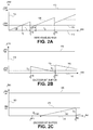
- the raw frame buffer model is shown in FIG. 2 a , where the horizontal axis 110 is the encoding time index and the vertical axis 120 is the raw frame buffer level.
- the minimum buffer level 115 and the maximum buffer level 125 are the upper and lower bounds of the raw frame buffer levels that the system desires to maintain.
- the raw frame buffer profile 135 is the achieved dynamic raw frame buffer level in this exemplary case.
- the fullness of the encoder bit buffer at time t is denoted by l enc (t)
- l enc (t) The fullness of the encoder bit buffer at time t is denoted by l enc (t)
- l enc (0) 0 and at the time t n enc when the encoder completes encoding frame n, b n bits corresponding to the access unit of the coded frame are added to the buffer.
- encoder buffer underflow poses no danger to the system.
- the complement situation of encoder bit buffer overflow occurs when l enc (t n enc )+b n ⁇ l tot enc .
- the encoder will stall until the bit buffer contains enough space to accommodate the encoded bits. If the stall lasts for a non-negligible amount of time, unpredictable results (including input raw frame buffer overflow) may occur.
- the buffer level has to be checked for undertow immediately before the encoder finishes encoding a frame, and for overflow immediately after the encoding is finished. Combining the contributions of bit production by the encoder and consumption by the transport subsystem, the encoder bit buffer levels are given by
- the encoder bit buffer model is shown in FIG. 2 b , where the horizontal axis 140 is the encoding time index and the vertical axis 150 is the encoder bit buffer level.
- the minimum buffer level 145 and the maximum buffer level 155 are the upper and lower bounds of the encoder bit buffer levels that the system desires to maintain.
- the encoder bit buffer profile 165 is the achieved encoder bit buffer level in this exemplary case. For convenience, let us denote by
- r n 1 t n enc - t n - 1 enc ⁇ ⁇ t n - 1 enc t n enc ⁇ r ⁇ ( t ) ⁇ d t ( 16 ) the average rate while the frame n being encoded.
- r n 1 t n enc - t n - 1 enc ⁇ ⁇ min ⁇ ⁇ l enc ⁇ ( t n - 1 enc + ⁇ ) , ⁇ t n - 1 enc t n enc ⁇ ⁇ max ⁇ ( t ) ⁇ d t ⁇ . ( 17 )
- the channel delay ⁇ chan needs not to be constant; in this case, maximum channel delay may be assumed.
- the decoder remains idle until l dec ⁇ l init dec ; once the bit buffer is sufficiently full, the decoder removes b 1 bits from the buffer and starts decoding the first frame of the sequence.
- the time lapsing between the arrivals of the first bit until the first access unit is removed from the bit buffer is given by the smallest ⁇ dec satisfying
- the decoder removes access units corresponding to the encoded frames at a constant rate F, resulting in the following decoding schedule
- the decoder bit buffer level assumes highest and lowest values immediately before frame decoding start, and immediately after the decoding is started, respectively. Combining the contributions of bit production by the transport subsystem and consumption by the decoder, the decoder bit buffer levels are given by
- the decoder bit buffer model is shown in FIG. 2 c , where the horizontal axis is the encoding time index 170 and the vertical axis is the decoder bit buffer level 180 .
- the minimum buffer level 175 and the maximum buffer level 185 are the upper and lower bounds of the decoder bit buffer levels that the system desires to maintain.
- the decoder bit buffer profile 195 is the achieved decoder bit buffer level in this exemplary case.
- the problem of sequence resource allocation consists of establishing a resource budget for the latter sequence of n frames.
- allocation of bit and encoding time budgets denoted by b T and ⁇ T , respectively are considered.
- the display time stamp relative to the beginning of the current GOP of the i-th frame is denoted by t i .
- an estimate ⁇ circumflex over ( ⁇ ) ⁇ of the decoder delay is available and denoted by
- t max max ⁇ ⁇ t max gop , ⁇ ⁇ ⁇ ( 25 )
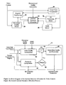
- the sequence-level controller flow diagram is shown in FIG. 3 where the Frame Type Decision 270 and Encoding Order Optimization 280 are the system design parameters that the sequence-level controller will produce to achieve the minimum sequence cost within the sequence budget.
- the Buffer Model 210 will extract buffer model for the raw frame buffer, encoder bit buffer and decoder bit buffer.
- the Encoder Model 260 acts on the frame decision f from Frame Type Decision 270 and the underlying sequence to produce parameters for encoder model.
- the encoder model with the associated parameters allow the system to evaluate the corresponding system cost and quality without actually performing the computationally expensive encoding process.
- the system costs described in FIG. 3 are bit budget and time budget. Nevertheless, other system costs can also be used by people skilled in the field.
- the Sequence Bit Budget Allocation 250 allocates the frame bit rate budget using the results from Encoder Model 260 and Buffer Model 210 to avoid the complexity associated with actually encoding process.
- the Sequence Time Budget Allocation 230 allocates the frame time budget using the results from Encoder Model 260 and Buffer Model 210 to avoid the complexity associated with actually encoding process.
- the Frame Bit Budget Allocation 240 Based on the frame bit budget by, the Frame Bit Budget Allocation 240 performs optimal bit budget allocation within the frame. The frame bit budget allocation is typically done on a smaller picture unit such as macroblock or block by assigning a proper quantization level.
- the Frame Time Budget Allocation 220 works in a similar way to that as Frame Bit Budget Allocation 240 .
- bit rate fluctuations result in a loss of such synchronization.
- encoding the next frames at the rate r will cause the decoder buffer level to drop and, eventually, to underflow, while keeping the encoder buffer level balanced.
- ⁇ circumflex over (r) ⁇ dec >r keeping the video stream rate at r will result in a decoder bit buffer overflow.
- a solution proposed here consists of modifying the rate at which the stream is encoded such that both buffers remain as balanced as possible.
- r eff max ⁇ min ⁇ 0.5( r enc + ⁇ circumflex over (r) ⁇ dec )+ ⁇ r ,max ⁇ r enc , ⁇ circumflex over (r) ⁇ dec ⁇ ,min ⁇ r enc , ⁇ circumflex over (r) ⁇ dec ⁇ , (32)
- ⁇ ⁇ ⁇ r 1 2 ⁇ t max ⁇ ⁇ l ⁇ dec - l enc + l min enc - l min dec : r ⁇ dec ⁇ r l max dec - l max enc - l enc + l ⁇ dec : r ⁇ dec ⁇ r ( 33 )
- the estimated amount of bits generated by the encoder for an i-th frame given a quantizer q i is given by
- ⁇ i ⁇ i b + ⁇ i b q i ( 35 )
- ⁇ b ( ⁇ 1 b , . . . , ⁇ b ) T
- ⁇ rem b ( n rem ⁇ n ) ⁇ b
- ⁇ rem b ( n rem ⁇ n ) ⁇ b
- sequence bit budget allocation is to maintain a fair distribution of the encoding bits throughout the sequence, considering the long-term effect of the decided allocation, as well as reacting to changes in channel bit rate and frame texture and motion complexity.
- the problem of sequence bit budget allocation can be translated to finding a single quantization scale q, which assigned to the remainder of the GOP frames produces b rem bits. Substituting the appropriate bit production models.
- the budget is constrained to be within 25% to 200% of the average bit budget
- Encoder and decoder bit buffer constrains are further imposed, yielding the following final expression for the sequence bit budget
- the time budget allocation problem consists of assigning the target encoding time ⁇ T for the observed frames n.
- encoding time allocation operates with shorter terms. Since frames are added to the encoder input buffer at the rate of F frames per second, the average encoding time of a frame is 1/F, resulting in the average budget
- ⁇ _ T n F ( 46 ) for the sequence of n observed frames.
- the time at the encoder should be n enc /F.
- the time at the encoder immediately prior to encoding the i-th frame usually differs from the ideal value.
- t dif n enc F - t enc - t 0 ( 47 ) the time difference between the ideal and actual encoding time; if t dif >0 the encoder is faster than the input raw frame rate and the encoding time budget has to be increased in order to avoid raw buffer underflow. Similarly, if t dif ⁇ 0, the encoder is lagging behind the input and the time budget has to be decreased in order to prevent an overflow. Demanding the encoder to close the time gap in n resp frames (n res /F seconds), yields the following encoding time budget
- ⁇ ′ ⁇ _ T + nt dif n resp ( 48 )
- n resp 5
- Encoder bit buffer constrains are further imposed yielding the final encoding time budget
- xT the resource budget assigned to the sequence by a higher-level sequence resource allocation algorithm.
- xT the resource budget assigned to the sequence by a higher-level sequence resource allocation algorithm.
- Other constrains stemming, for example, from the encoder buffer conditions apply as well.
- an allocation vector x is feasible if it satisfies that set of conditions, and infeasible otherwise. Resource allocation can be therefore thought of as finding a feasible solution to the maximization problem.
- b bit allocation vector
- q and q′ may assume only discrete values, we relax this restriction by making them continuous variables.
- the initial decoder buffer fullness ⁇ circumflex over (l) ⁇ ⁇ dec ⁇ circumflex over (l) ⁇ 0 dec is given as the input. In vector notation, we can write
- ⁇ ⁇ 1 , . . . , ⁇ n
- c c 1 , . . . , cn
- the encoder buffer constrains include both the encoder bit buffer constrains, applying to the output bit buffer, and the encoder raw buffer constrains, applying to the input raw frame buffer.
- ⁇ circumflex over (l) ⁇ i ⁇ raw and ⁇ circumflex over (l) ⁇ i+ raw denote the estimated encoder raw frame buffer fullness immediately before and immediately after frame i's encoding is complete.
- the initial buffer level at time 0 is denoted by l 0 raw and is available from a direct observation.
- the buffer-constrained encoding complexity allocation problem can be expressed as
- the first drawback stems from our assumption that encoding end time for a frame i coincides with the encoding start time for the frame i+1. For example, if the i frame is dropped and the input buffer level falls below l min enc , the encoder will stall until the minimum buffer level is reached. This will make ⁇ i non-negligible, which in turn will require ci to be very high (or even infinite if we assume that the nominal encoding time for a dropped frame is strictly zero). We overcome this problem by relaxing the constrain c ⁇ cmax.
- the second difficulty in the allocation problem (71) stems from the fact that sometimes the input and output buffer constrains may be conflicting (or, more formally, the feasible region may be empty).
- the time complexity allocation (73) is solved using Algorithm 2 similar to Algorithm 1 for bit allocation.
- Algorithm 2 similar to Algorithm 1 for bit allocation.
- ⁇ t ( ⁇ 1 t + ⁇ 1 t q′ 1 , . . . , ⁇ 1 t + ⁇ 1 t q′) T .
- Algorithm 2 Max-min frame time complexity allocation. input : n ⁇ 1 vectors ⁇ t of time model parameters; initial encoder bit buffer level l 0 ENC ; initial encoder raw frame buffer level l 0 raw ; time budget ⁇ T; measured average encoder buffer draining rate r; frame rate F output :n ⁇ 1 optimal max-min complexity allocation vector c*; n ⁇ 1 CPU time utilization vector ⁇ . 1.
- ⁇ T max ⁇ T ⁇ c( ⁇ 1 t , . . . , ⁇ m t )1, 0 ⁇ 8
- ⁇ t ( ⁇ m+1 t , . . . , ⁇ n t ) T
- l 0 enc l 0 enc + ( ⁇ circumflex over (b) ⁇ 1 , . . . , ⁇ circumflex over (b) ⁇ m )1 ⁇ r ⁇ T 0
- l 0 raw l 0 raw + F( ⁇ 1 t , . . .
- the convergence condition can be a bound on the change in c* and q*, the number of iterations, or any combination thereof. Our practice shows that a single iteration of this algorithm usually produces acceptable allocation.
- the purpose of frame type decision is to associate with a sequence of n frames an optimal sequence of frame types.
- the frame type with which an i-th frame is encoded is denoted by f i .
- f i also specifies whether the frame is used as reference, whether it is an IDR, and which frames are used for its temporal prediction (unless it is a spatially predicted frame).
- the space of possible frame type assignment for a frame i is denoted by F i , and depends solely on the status of the reference buffer immediately before the frame is encoded, denoted by R i (R i is defined as the list of reference frame indices).
- ⁇ i fully defines the instantaneous encoder state.
- f i does not fully define the set of control parameters required by the encoder in order to encode the i-th frame, as it does not specify the quantization and complexity scales q i and c i .
- the amount of bits produced and the amount of time consumed by encoding the i-th frame can be expressed as functions of f.
- f the latter quantities
- pi the distortion of the i-th frame.
- the distortion is evaluated as the PSNR of the difference between the original frame i and the last displayed frame t i nd .
- a i (f i , q* i , c* i ) as the encoder action for the frame i.
- a i (f i , q* i , c* i )
- the optimal values of q* i and c* i depend on the f i 's of the entire sequence of frames 1 , . . . , n.
- a can be determined only as a whole, i.e. a i+1 is required in order to determine a i .
- the last IDR presentation time stamp is updated according to
- the reference buffer is updated according to the sliding window policy
- the remaining constituents of the encoder state ⁇ circumflex over ( ⁇ ) ⁇ i NM ( l i ⁇ enc ,l i ⁇ raw ,l i ⁇ dec ) (87) are non-Markovian, since their update rule requires and which, in turn, depend on the entire sequence f through q* and c*.
- Buffer cost penalizing the estimated decoder bit buffer violation is defined as
- p buf ⁇ ( l ⁇ k + dec ) h os ⁇ ( l ⁇ k + dec , l min dec ) + h os ⁇ ( l tot dec - l ⁇ k + dec , l tot dec - l max dec ) ⁇ ⁇
- ⁇ l ⁇ i + dec l ⁇ i - dec - b ⁇ i
- ⁇ circumflex over (p) ⁇ i min is computed as the 0.1%-quantile of the PSNR of the difference between the original frame i and the last displayed frame l i nd
- ⁇ circumflex over (p) ⁇ i min ⁇ circumflex over (p) ⁇ i .
- p idr ⁇ ( t i , t i idr ) ⁇ ⁇ : t i - t i idr > t max gop 0 : t i - t i idr ⁇ t min idr t i - t i idr - t i idr t max gop - t min idr : else , ( 95 ) penalizing for a too late IDR frame.
- the cost is constructed in such a way that an IDR is placed in the time interval [t min idr ,t max gop ].
- Bit budget deviation cost penalizes for action sequences resulting in a deviation from the allocated bit budget b T
- the frame type optimization problem can be expressed as the minimization problem
- ⁇ circumflex over (q) ⁇ (b) is the inverse function of ⁇ circumflex over (b) ⁇ (q) given by
- p _ ⁇ ( f i ) ⁇ dis ⁇ P dis ( f i , p ⁇ _ ) + ⁇ drop ⁇ P drop ( p ⁇ _ , p ⁇ i mi ⁇ n ) + ⁇ idr ⁇ P idr ⁇ ( f i , t i , t i idr ) ( 105 ) (though a lower bound on the buffer penalty ⁇ buf can also be devised, we do not use it here for simplicity). Note that unlike ⁇ , ⁇ is additive, that is
- the lower bound ⁇ (a) is used in the branch and bound Algorithm 4 for solving the combinatorial minimization problem (102).
- the order of the loop searching over all feasible frame types F 1 should be selected to maximize the probability of decreasing the bound ⁇ as fast as possible.
- the best ordering of F is DROP, followed by P (if multiple reference frames are available, they are ordered by increasing display time difference relative to the current frame), followed by IDR.
- non-IDR I frames and non-reference P or B frames can be straightforwardly allowed for as well.
- complexity allocation may be removed from the frame type decision algorithm and performed after the optimal frame types are assigned.
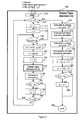
- FIG. 4 A flow chart corresponding to the Branch and bound frame type decision algorithm is shown in FIG. 4 , where the frame type decision function is shown as a recursive process.
- the Frame Type Decision (n) 300 with n frames is shown to call itself with (n ⁇ 1) frames as the parameters, i.e., Frame Type Decision (n ⁇ 1) 350 .
- the function first checks whether the recursion reaches end, i.e., whether n ⁇ 0. If the recursion reaches its end, the algorithm outputs frame bit budget b T at step 370 for the Frame Bit Budget Allocation to come up the optimal allocation q* at step 372 .
- the frame complexity in term of processing time is computed at step 374 and the Frame Time Budget Allocation derives the optimal encoder complexity allocation c* according the frame processing time ⁇ T at step 376 .
- the optimal actions sequence a* and associated sequence cost ⁇ * are updated at steps 378 and 380 .
- the optimal sequence cost ⁇ * is then compared with the lower bound ⁇ at step 382 and the lower bound is updated if ⁇ * is smaller than ⁇ , at step 384 .
- This processing is also described in the sequence-level controller flow diagram as shown in FIG. 3 .
- the system initializes the sequence cost function by assigning its value to infinity at step 312 and starts the iteration for every possible frame type f 1 .
- the number of all frame type of F 1 is denoted by L(F 1 ) the index i used to process all possible frame types by initializing i to 1 at step 314 and checking the ending condition i ⁇ L(F 1 ) at step 366 .
- the corresponding sequence cost is computed and compared with the lower bound at ⁇ step 320 . If the computed cost is higher than the lower bound, no further processing is needed as shown as the “yes” branch at step 320 .
- the Markovian encoder state is updated at step 322 and the frame type f 1 is added to the sequence frame type f at step 324 . Both the frame index n and the frame type index i are updated at step 326 . After the frame index is decremented by 1, the Frame Type Decision recursion occurs as the step 350 is within in main function at step 300 . The corresponding action sequence, sequence cost, and lower bound on the sequence cost are updated at step 360 . The sequence cost is then compared with the optimal cost at step 362 and the optimal action sequence and sequence cost are updated at step 364 if the newly computed cost is lower.
- encoding order optimization Given a sequence of n frames indexed by incrementing display order, the purpose of encoding order optimization is to find their optimal encoding order.
- the frame reordering as a permutation ⁇ of ⁇ 1, . . . , n ⁇ .
- a*( ⁇ ) and ⁇ *( ⁇ ) the optimal action sequence and its cost, respectively, found using the frame type decision algorithm from the previous section applied to the ordered sequence of frames ⁇ 1 , . . . , ⁇ n .
- encoding order optimization can be expressed as finding the permutation minimizing
- the search space of feasible permutations is constrained by the decoded picture buffer level.
- the decoded picture buffer is shared with the reference buffer.
- the flow chart of the encoding order optimization algorithm is shown in FIG. 5 .
- the process starts with n frames at step 400 and an initial sequence cost of infinity.
- the total number for possible sequence order is K.
- iteration is used with index k with initial value of 1 at step 415 and the termination condition is checked at step 420 .
- the reference buffer is verified at step 425 and the reference buffer is compared with the maximum buffer size for all i at step 430 and no further processing is the overflow condition occurs. If the buffer condition is satisfied, the optimal frame type decision is invoked at step 435 and the sequence cost corresponding to the action sequence is calculated at step 440 .
- the lower bound is also compared with this new sequence cost and is updated as well.
- the new sequence cost is compared with the optimal cost at step 445 . If the new cost is lower than the optimal cost, the optimal cost, optimal action sequence and optimal sequence order are all updated at step 450 . When the process is complete at step 460 , the final optimal sequence order, optimal action sequence and sequence cost are the outputs from the encoding order optimization algorithm.
Abstract
Description
where d is the MSE and ymax is the maximum allowed value of the luma pixels, typically 255 if the luma data has an 8-bit precision and is represented in the
-
- A. Content-aware encoder model—an accurate encoder model based on visual clues, allowing optimizing the resource allocation prior to encoding,
- B. Optimal frame type decision—including IDR insertion at scene cuts, optimization of frame dropping capable of detecting and removing redundant frames, e.g. due to telecine conversion, and optimal reference frame selection based on frame predictability, allowing to achieve compression ratios close to those of codecs using multiple reference frames at significantly lower computational complexity,
- C. Optimal encoding order decision—allowing out-of-order encoding to achieve better predictability,
- D. Optimal frame bit allocation, and
- E. Optimal encoding time allocation, allowing achieving better encoding quality by distributing encoding time between frames according to their coding complexity.
Content-Aware Encoder Model
where {circumflex over (x)}i is a macroblock-wise predictor, θi are the encoding parameters and zi are the visual clues in macroblock i, NMB is the number of macroblocks in the frame and K is some normalization factor. Specifically, the following models are used.
Bit Production Model
{circumflex over (b)} i(q i ,z i)=α1+α2 z i q i −1 (4)
where α1,α2≦0 are the model parameters obtained by training. Assuming that q is constant for the entire frame, the frame-wise predictor of the amount of bits can be therefore expressed as
where the coefficients αb=NMBα1 and βb=Σi=1 N
Distortion Model
{circumflex over (p)} i(q i ,z i)=β1−β2 z i−β3 q′ i (6)
where β1,β2,β3≧0 are the model parameters obtained by training. Assuming that q′i is constant for the entire frame, the predictor of the frame-wise average PSNR can be therefore expressed as
where the coefficients
and
depend on the frame content and frame type.
Distortion Model for Dropped Frames
{circumflex over (τ)}′i(q i ,z i)=max{min{γ1+γ2 z i−γ3 q′ i,1},0}T (8)
where γ1,γ2,γ3≧0 are the model parameters obtained by training, and zi and q′ are the texture complexity (for I-frames) and motion complexity (for P-frames) respectively. The minimum and maximum is taken in order to ensure that the predicted normalized time value is within a valid range of [0,T] (for a reasonable range of zi and q′, this assumption will hold). Assuming that q′ is constant for the entire frame, the predictor of the encoding time for the entire frame is approximated (neglecting the possible nonlinearity due to the minimum and maximum functions) as
where the coefficients
depend on the frame content and frame type.
Buffer Models
t 1 enc =t 0+τ1 (11)
l raw(t n enc−ε)=t n enc F−n+1. (13)
the average rate while the frame n being encoded. Assuming that r(t)=rmax(t) if lenc(t)>0, and r(t)=0 otherwise, we obtain
l enc(t n enc−ε)=l enc(t n−1 enc+ε)−(t n enc −t n−1 enc)r n (18)
Decoder Bit Buffer Model
We denote by
t 1 dec =t 1 enc+δchan+δdec (20)
the time when the first frame starts being decoded The delay passing between production and consumption of the access unit corresponding to a frame is denoted by
δ=δchan+δdec (21)
The maximum GOP duration (if the duration is smaller than the estimated delay, tmax={circumflex over (δ)} is used). The minimum GOP duration is set to the minimum temporal distance between two consecutive IDR frames,
t min =t min idr. (26)
t rem =t max −t i, (27)
from where the number of remaining frames,
n rem =t rem F (28)
is obtained.
{circumflex over (r)} dec ≈r(t enc+δ), (29)
where r is the current rate. Assuming the simplistic model of the rate remaining constant r in the interval [tenc,tenc+δ], and then remaining constant {circumflex over (r)}dec, the average bit rate of the encoder buffer drain in the interval [tenc,tenc+tmax] is given by
l enc(t)+l dec(t+δ)=l tot enc. (31)
r eff=max{min{0.5(r enc +{circumflex over (r)} dec)+Δr,max{r enc ,{circumflex over (r)} dec}},min{r enc ,{circumflex over (r)} dec}}, (32)
where
b rem =r eff t rem. (34)
where the coefficients αb=(α1 b, . . . , αb)T and βb=(β1 b, . . . , βb)T depend on the frame content and frame type fi. The latter is assumed to be assigned by a higher-level frame type decision algorithm and
denote the sum of the model coefficients of the observed n frames. Substituting αb and βb into the bit production model yields the total estimate of bits produced by encoding the observed frames i, . . . , i+n−1 with a constant quantizer. Similarly, we denote by
αrem b=(n rem −n)
βrem b=(n rem −n)
the model coefficients for estimating the amount of bits of the remaining frames in the current GOP;
and solving for 1/q yields,
is a scaling factor decreasing the bit budget for higher, and increasing for lower decoder bit buffer levels, respectively; {circumflex over (l)}dec={circumflex over (l)}dec(ti dec−ε) is the estimated decoder bit buffer fullness immediately prior to decoding the i-th frame, ε1=3, and h is the target relative decoder bit buffer level, defined as
resulting in
b′ T=min{max{b′ T,0.25
where lenc enc is the encoder bit buffer level immediately prior to encoding the i-th frame.
Encoding Time Budget Allocation
for the sequence of n observed frames. Using this budget and assuming the encoder has encoded nenc frames so far (including the dropped ones), the time at the encoder should be nenc/F. However, since the actual encoding time may differ from the allocated budget, the time at the encoder immediately prior to encoding the i-th frame (relative to the time t0 when the first frame in the sequence starts being encoded) usually differs from the ideal value. We denote by
the time difference between the ideal and actual encoding time; if tdif>0 the encoder is faster than the input raw frame rate and the encoding time budget has to be increased in order to avoid raw buffer underflow. Similarly, if tdif<0, the encoder is lagging behind the input and the time budget has to be decreased in order to prevent an overflow. Demanding the encoder to close the time gap in nresp frames (nres/F seconds), yields the following encoding time budget
τT n=max{min{τ′T,1.5
and {circumflex over (b)}i are the expected bits produced by encoding the i-th frame. Due to the dependence on {circumflex over (b)}i, the time allocation must be preceded by bit allocation.
Frame Resource Allocation
where xT is the resource budget assigned to the sequence by a higher-level sequence resource allocation algorithm. Other constrains stemming, for example, from the encoder buffer conditions apply as well. Formally, we say that an allocation vector x is feasible if it satisfies that set of conditions, and infeasible otherwise. Resource allocation can be therefore thought of as finding a feasible solution to the maximization problem.
as finding a max-min optimal resource allocation x*=x(θ*). In the remainder of this section, we are going to explore and formulate allocation problems for two types of resources considered here, namely coded bits and encoding time.
Bit Allocation
K=J−I, and r^dec is the estimated average decoder bit buffer filling rate on the time interval
where lmin dec and lmax dec are the minimum and the maximum decoder big buffer levels, respectively. Since it is reasonable to assume a monotonically decreasing dependence of the PSNR in the quantization parameter (or the quantizer scale), the maximizer of (60) coincides with the minimizer of
where the coefficients αb=(α1 b, . . . , αb)T and βb=(β1 b, . . . , βn b)T depend on the frame content and frame types. In vector notation, this yields
where vector division is interpreted as an element-wise operation. The algorithm can be easily adopted to other models as well by replacing the closed-form solution in
with respect to the scalar q.
| Algorithm 1: Max-min frame bit allocation |
| input: | n × 1 vectors αb, βb of bit model parameters; n × 1 vector of decoding time stamps tdec | |
| starting with t1 dec = 0; initial decoder bit buffer level l0 dec bit budget bT; | ||
| estimated average decoder buffer rate {circumflex over (r)}dec | ||
| output: | n × 1 optimal max-min quantizer allocation vector q*. |
| 1 | Find optimal equal quantizer allocation |
| | |
| and set q = q · 1 |
| 2 | if {circumflex over (l)}— dec(q) ≦ lmax dec and | {circumflex over (l)}+ dec(q) ≧ lmax dec then |
| 3 | set q* = q. |
| 4 | else |
| 5 | Find the smallest 1 ≦ m ≦ n for which one of the constrains is violated. |
| 6 | if {circumflex over (l)}min− dec(q) ≦ lmax dec then set bT 0 = l0 dec + {circumflex over (r)}dectm+1 dec − lmax dec else set bT 0 = l0 dec + {circumflex over (r)}dectm dec − lmin dec. |
| 7 | Set bT 0 = max {bT 0, 0} |
| 8 | Find |
| | |
| and set q1*= . . . = qm* = q |
| 9 | Compute remaining bit budget |
| | |
| 10 | Recursively invoke the algorithm with α = (αm+1 b, . . . , αn+1 b)T, tdec = (tm+1 dec, . . . , tn dec)T − tm+1 dec, |
| and l0 dec = l0 dec − bT 0{circumflex over (r)}dectm+1 dec to fix the remaining quantizer values (qm+1*, . . . , qn*) |
| 11 end |
Encoding Time Allocation
{circumflex over (t)} enc =J{circumflex over (τ)}(c) (65)
where τ^=(^τ1, . . . , τ^n)T denotes the estimated encoding times.
{circumflex over (l)} − enc(c)=l 0 enc +K{circumflex over (b)}−rJ{circumflex over (τ)}(c) (66)
{circumflex over (l)} + enc(c)=l 0 enc +J{circumflex over (b)}−rJ{circumflex over (τ)}(c) (67)
{circumflex over (l)} raw({circumflex over (t)} i enc−ε)=l 0 raw +{circumflex over (t)} i enc F−(i−1) (68)
and {circumflex over (l)}raw({circumflex over (t)}i enc+ε)={circumflex over (l)}raw({circumflex over (t)}i enc−ε)−1. In vector form, this yields
{circumflex over (l)} − raw(c)=l 0 raw +FJ{circumflex over (τ)}(c)−K1 (69)
{circumflex over (l)} + raw(c)=l 0 raw +FJ{circumflex over (τ)}(c)−J1 (70)
and c=min{c*,cmax} the encoding complexity scale of frames with ci* exceeding cmax will be set to cmax, and the utilizable CPU time will be lower than 100%. The second difficulty in the allocation problem (71) stems from the fact that sometimes the input and output buffer constrains may be conflicting (or, more formally, the feasible region may be empty).
where the constrains are interpreted as ordered constrains.
where the coefficients and αt=(α1 t, . . . , αn t)T and βt=(β1 t, . . . , βn t)T depend on the frame content and frame types, and γt=(α1 t+β1 tq′1, . . . , α1 t+β1 tq′)T.
Joint Bit and Encoding Time Allocation
{circumflex over (l)} − enc(q,c)=l 0 enc +K{circumflex over (b)}(q,c)−rJ{circumflex over (τ)}(c) (75)
{circumflex over (l)} + enc(q,c)=l 0 enc +J{circumflex over (b)}(q,c)−rJ{circumflex over (τ)}(c) (76)
and the decoder bit buffer levels
{circumflex over (l)} − dec(q,c)=l 0 dec +K{circumflex over (b)}(q,c)+{circumflex over (r)}dec t dec (77)
{circumflex over (l)} + dec(q,c)=l 0 dec −J{circumflex over (b)}(q,c)+{circumflex over (r)}dec t dec (78)
| Algorithm 2: Max-min frame time complexity allocation. |
| input | : n × 1 vectors γt of time model parameters; initial encoder bit buffer level l0 ENC; initial | |
| encoder raw frame buffer level l0 raw; time budget τT; measured average encoder buffer | ||
| draining rate r; frame rate F | ||
| output | :n × 1 optimal max-min complexity allocation vector c*; n × 1 CPU time utilization | |
| vector η. |
| 1. | Find optimal equal complexity scale allocation |
| |
| and set c = c · 1. | |
| 2. | if {circumflex over (l)}+ enc(c) ≦ lmax enc and {circumflex over (l)}− enc(c) ≧ lmin enc and {circumflex over (l)}− raw(c) ≦ lmax raw and {circumflex over (l)}+ raw(c) ≧ lmin raw then set c* = c |
| else |
| 3 | Find the smallest 1 ≦ m ≦ n for which one of the constrains is violated. |
| 4 | Compute the complexity constrains |
| | |
| and set c1 = max{max{c1, c3}, cmin} and c2 = min{c2, c4}. | |
| 5 | if {circumflex over (l)}m+1 enc(c) ≦ lmax enc or {circumflex over (l)}m+ raw(c) ≧ lmin raw then set τT 0 = cmin(γ1 t, . . . , γm t)1 else set |
| τT 0 = cmax(γ1 t, . . . , γm t)1 | |
| 6 | Find |
| | |
| and set c1* = . . . = Cm* = c. | |
| 7 | Compute remaining time budget τT = max{τT −c(γ1 t, . . . , γm t)1, 0} |
| 8 | Recursively invoke the algorithm with γt = (γm+1 t, . . . , γn t)T, l0 enc = l0 enc + |
| ({circumflex over (b)}1, . . . , {circumflex over (b)}m)1−rτT 0 and l0 raw = l0 raw + F(γ1 t, . . . , γm t)1−m to fix the remaining complexity | |
| scale values (cm+1*, . . . , cn*). | |
| 9 | Set η = cmax/c* and c* = max{c*, cmax} |
| 10 | end |
which now depend on both q and c. Unfortunately, a joint bit and time complexity allocation problem is not well-defined, since combining the two vector-valued objectives q and c can no more be treated using the max-min optimality framework, as the two vectors are non-commensurable.3 However, joint allocation can be performed by alternatively solving the bit and time allocation problems, as suggested by the following algorithm
| Algorithm 3: Joint frame bit and encoding complexity allocation. |
| Initialization: Set c* = 1 | |
| 1 repeat | |
| 2 Fix c = c* and find the optimal quantizer allocation | |
| q* by solving (61). | |
| 3 Fix q = q* and find the optimal time complexity allocation | |
| c*by solving (73). | |
| 4 until until convergence | |
σi=(R i ,l i− enc ,l i− raw ,l i− dec ,t i nd ,t i idr) (79)
where c li− enc, li− raw, and li− dec denote the levels of the encoder bit buffer, raw buffer, and decoder bit buffer, respectively, denotes the index of the last non-dropped frame, and denotes the presentation time of the last IDR frame. σi fully defines the instantaneous encoder state. In practice, only estimated buffer levels are available. We will henceforth denote the estimated encoder state by
σi=(R i ,{circumflex over (l)} i− enc ,{circumflex over (l)} i− raw ,{circumflex over (l)} i− dec ,t i nd ,t i idr) (80)
{circumflex over (l)} i+1− enc ={circumflex over (l)} i− enc +{circumflex over (b)} i −r i{circumflex over (τ)}i
{circumflex over (l)} i+1− raw ={circumflex over (l)} i− raw +F{circumflex over (τ)} i−1
{circumflex over (l)} i+1− dec ={circumflex over (l)} i− dec +{circumflex over (b)} i +{circumflex over (r)} i dec(t i+1 dec −t i dec), (81)
where ti dec is the decoding time stamp of the i-th frame, ri is the average encoder bit buffer draining rate at the time ti enc, and {circumflex over (r)}i is the predicted decoder bit buffer filling rate at the time ti dec. The last displayed is updated according to
where min Ri denotes the smallest frame index found in the reference buffer, |Ri| denotes the number of frames in the reference buffer, and Rmax stands for the maximum reference buffer occupancy. It is important to emphasize that though the
σi M=(R i ,l i nd ,t i idr) (85)
the Markovian part of the state, whose update rule can be expressed as
σi+1 M=σ(σi M ,f i) (86)
(note the dependence on fi only). On the other hand, the remaining constituents of the encoder state
{circumflex over (σ)}i NM=(l i− enc ,l i− raw ,l i− dec) (87)
are non-Markovian, since their update rule requires and which, in turn, depend on the entire sequence f through q* and c*. The update rule for σi NM is a function of the initial state σl NM, and the entire f
σi NM=σ(σ1 NM ,f) (88)
Action Sequence Cost
where typically λbuf=10, λdis=1, λbit=100, λidr=0.5, λqp=0.01 The constituent terms of the cost function are defined as follows.
is a single-sided hyperbolic penalty function, and ε is a small number, typically ε≈10−6
p dis({circumflex over (p)} i)=2552·10−0.1{circumflex over (p)}i. (92)
where {circumflex over (p)}i min is the estimated minimum PSNR. For a dropped frame, {circumflex over (p)}i min is computed as the 0.1%-quantile of the PSNR of the difference between the original frame i and the last displayed frame li nd For a non-dropped frame, {circumflex over (p)}i min={circumflex over (p)}i.
penalizing for a too late IDR frame. The cost is constructed in such a way that an IDR is placed in the time interval [tmin idr,tmax gop].
P idr(q′ i)=max{2q′
where
and ε=0.1.
Action Sequence Optimization
where {circumflex over (q)}(b) is the inverse function of {circumflex over (b)}(q) given by
(the model coefficients αi b and βi b depend on fi). For dropped frames, the bound is exact; moreover, {circumflex over (p)}i min can be estimated as well.
(though a lower bound on the buffer penalty ρbuf can also be devised, we do not use it here for simplicity). Note that unlike ρ, ρ is additive, that is
| input : | sequence of n frames; best frame type decision f so far; initial non-Markovian state |
| {circumflex over (σ)}1 NM ; current Markovian state σ1 M | |
| output : | optimal action sequence a*; optimal action sequence cost p* = p(a *) ;lower bound |
| ρ. | |
| 1 if n ≦ 0 then |
| // Leaf reached |
| 2 From f and {circumflex over (σ)}1 NM , allocate the sequence bit budget bT |
| 3 Find optimal frame quantizer allocation q* . |
| 4 From f and {circumflex over (σ)}1 NM , allocate the sequence encoding time budget τT |
| 5 Find optimal frame encoding complexity allocation c* |
| 6 Form action sequence a* = (f ,q* ,c*). |
| 7 Compute sequence cost ρ* = ρ(a* ,{circumflex over (σ)}) |
| 8 if ρ* <ρ then update lower bound ρ = ρ* |
| 9 else |
| 10 Set ρ* = ∞. |
| 11 for all f1 ε F1 do |
| 12 if ρ(f1) >ρ then continue // Prune subtree |
| 13 Compute the updated Markovian encoder state σ2 M = σ(σ1 M ,f1). |
| 14 Add f1 to the current f and invoke the algorithm recursively for the remaining n − 1 frames |
| in the sequence, producing the action sequence a, its cost ρ, and an updated bound ρ. |
| 15 if ρ < ρ* then ρ* = ρ,a* = a . // Update current best action sequence |
| 16 end |
| 17 end |
where con(Ri) denotes the largest subsequence of consecutive frame indices in Ri starting with min Ri (e.g., if Ri={1, 2, 3, 5}, con(Ri)={1, 2, 3}; if R Ri={1, 3, 4, 5}, con(Ri)={1}, etc). We also modify the state update rule for the reference buffer as
and con(Ri,k) denotes the sequence of at most k smallest elements in con(Ri) (or less, if |con(Ri)|<k). Note that πi replaces i, and the update scheme now allows frames to be locked in the reference buffer until a consecutive sequence is formed.
| input : | sequence of n frames. | |
| output: | optimal permutation π; optimal action sequence | |
| a* ; optimal action sequence cost | ||
| ρ* = ρ(a*) | ||
| initialization: | Set ρ = ρ* = ∞. | |
| 1 for all π do | |
| 2 Verify reference buffer conditions. | |
| 3 if |Ri| > Rmax for any i then continue | |
| 4 Invoke the frame type decision algorithm on the sequence of | |
| frames π1, ..., πn, producing the action sequence a, | |
| its cost ρ, and an updated bound ρ. | |
| 5 if ρ < ρ*, then ρ* = ρ, a* = a, π* = π. | |
| 6 end | |
Claims (3)
Priority Applications (1)
| Application Number | Priority Date | Filing Date | Title |
|---|---|---|---|
| US12/199,741 US8259794B2 (en) | 2008-08-27 | 2008-08-27 | Method and system for encoding order and frame type selection optimization |
Applications Claiming Priority (1)
| Application Number | Priority Date | Filing Date | Title |
|---|---|---|---|
| US12/199,741 US8259794B2 (en) | 2008-08-27 | 2008-08-27 | Method and system for encoding order and frame type selection optimization |
Publications (2)
| Publication Number | Publication Date |
|---|---|
| US20100054329A1 US20100054329A1 (en) | 2010-03-04 |
| US8259794B2 true US8259794B2 (en) | 2012-09-04 |
Family
ID=41725390
Family Applications (1)
| Application Number | Title | Priority Date | Filing Date |
|---|---|---|---|
| US12/199,741 Expired - Fee Related US8259794B2 (en) | 2008-08-27 | 2008-08-27 | Method and system for encoding order and frame type selection optimization |
Country Status (1)
| Country | Link |
|---|---|
| US (1) | US8259794B2 (en) |
Cited By (14)
| Publication number | Priority date | Publication date | Assignee | Title |
|---|---|---|---|---|
| US20100086062A1 (en) * | 2007-01-23 | 2010-04-08 | Euclid Discoveries, Llc | Object archival systems and methods |
| US20110060792A1 (en) * | 2009-09-08 | 2011-03-10 | Swarmcast, Inc. (Bvi) | Dynamic Selection of Parameter Sets for Transcoding Media Data |
| US20110182352A1 (en) * | 2005-03-31 | 2011-07-28 | Pace Charles P | Feature-Based Video Compression |
| US20120219062A1 (en) * | 2011-02-28 | 2012-08-30 | Cisco Technology, Inc. | System and method for managing video processing in a network environment |
| US20130089107A1 (en) * | 2011-10-05 | 2013-04-11 | Futurewei Technologies, Inc. | Method and Apparatus for Multimedia Queue Management |
| US8842154B2 (en) | 2007-01-23 | 2014-09-23 | Euclid Discoveries, Llc | Systems and methods for providing personal video services |
| US8902971B2 (en) | 2004-07-30 | 2014-12-02 | Euclid Discoveries, Llc | Video compression repository and model reuse |
| US8908766B2 (en) | 2005-03-31 | 2014-12-09 | Euclid Discoveries, Llc | Computer method and apparatus for processing image data |
| US9532069B2 (en) | 2004-07-30 | 2016-12-27 | Euclid Discoveries, Llc | Video compression repository and model reuse |
| US9578345B2 (en) | 2005-03-31 | 2017-02-21 | Euclid Discoveries, Llc | Model-based video encoding and decoding |
| US9621917B2 (en) | 2014-03-10 | 2017-04-11 | Euclid Discoveries, Llc | Continuous block tracking for temporal prediction in video encoding |
| US9743078B2 (en) | 2004-07-30 | 2017-08-22 | Euclid Discoveries, Llc | Standards-compliant model-based video encoding and decoding |
| US10091507B2 (en) | 2014-03-10 | 2018-10-02 | Euclid Discoveries, Llc | Perceptual optimization for model-based video encoding |
| US10097851B2 (en) | 2014-03-10 | 2018-10-09 | Euclid Discoveries, Llc | Perceptual optimization for model-based video encoding |
Families Citing this family (36)
| Publication number | Priority date | Publication date | Assignee | Title |
|---|---|---|---|---|
| KR101557504B1 (en) * | 2009-04-13 | 2015-10-07 | 삼성전자주식회사 | Method for transmitting adapted channel condition apparatus using the method and providing system |
| US9756468B2 (en) | 2009-07-08 | 2017-09-05 | Dejero Labs Inc. | System and method for providing data services on vehicles |
| US8942215B2 (en) | 2010-07-15 | 2015-01-27 | Dejero Labs Inc. | System and method for transmission of data from a wireless mobile device over a multipath wireless router |
| US10033779B2 (en) | 2009-07-08 | 2018-07-24 | Dejero Labs Inc. | Multipath data streaming over multiple wireless networks |
| US10117055B2 (en) | 2009-07-08 | 2018-10-30 | Dejero Labs Inc. | System and method for providing data services on vehicles |
| US9585062B2 (en) | 2010-07-15 | 2017-02-28 | Dejero Labs Inc. | System and method for implementation of dynamic encoding rates for mobile devices |
| US10165286B2 (en) | 2009-07-08 | 2018-12-25 | Dejero Labs Inc. | System and method for automatic encoder adjustment based on transport data |
| KR101750048B1 (en) | 2009-11-13 | 2017-07-03 | 삼성전자주식회사 | Method and apparatus for providing trick play service |
| JP5484140B2 (en) * | 2010-03-17 | 2014-05-07 | Kddi株式会社 | Objective image quality evaluation device for video quality |
| KR20110105710A (en) * | 2010-03-19 | 2011-09-27 | 삼성전자주식회사 | Method and apparatus for adaptively streaming content comprising plurality of chapter |
| US8689275B2 (en) * | 2010-11-02 | 2014-04-01 | Xyratex Technology Limited | Method of evaluating the profit of a substream of encoded video data, method of operating servers, servers, network and apparatus |
| US9635385B2 (en) * | 2011-04-14 | 2017-04-25 | Texas Instruments Incorporated | Methods and systems for estimating motion in multimedia pictures |
| US9025672B2 (en) * | 2011-05-04 | 2015-05-05 | Cavium, Inc. | On-demand intra-refresh for end-to end coded video transmission systems |
| US9948938B2 (en) * | 2011-07-21 | 2018-04-17 | Texas Instruments Incorporated | Methods and systems for chroma residual data prediction |
| US8711928B1 (en) * | 2011-10-05 | 2014-04-29 | CSR Technology, Inc. | Method, apparatus, and manufacture for adaptation of video encoder tuning parameters |
| US9374585B2 (en) * | 2012-12-19 | 2016-06-21 | Qualcomm Incorporated | Low-delay buffering model in video coding |
| US20140177701A1 (en) * | 2012-12-26 | 2014-06-26 | Thomson Licensing | System and method for time budget achievement in real-time video encoding |
| US10045032B2 (en) * | 2013-01-24 | 2018-08-07 | Intel Corporation | Efficient region of interest detection |
| US9826015B2 (en) * | 2013-09-04 | 2017-11-21 | Qualcomm Incorporated | Dynamic and automatic control of latency buffering for audio/video streaming |
| GB2518909B (en) * | 2013-12-16 | 2015-10-28 | Imagination Tech Ltd | Encoder adaptation |
| EP3175617A4 (en) * | 2014-07-31 | 2018-02-28 | Dejero Labs Inc. | System and method for automatic encoder adjustment based on transport data |
| US20170085886A1 (en) * | 2015-09-18 | 2017-03-23 | Qualcomm Incorporated | Variable partition size for block prediction mode for display stream compression (dsc) |
| US10062409B2 (en) | 2016-09-23 | 2018-08-28 | Apple Inc. | Automated seamless video loop |
| US10176845B2 (en) | 2016-09-23 | 2019-01-08 | Apple Inc. | Seamless forward-reverse video loops |
| US10062410B2 (en) | 2016-09-23 | 2018-08-28 | Apple Inc. | Automated seamless video loop |
| US10122940B2 (en) | 2016-09-23 | 2018-11-06 | Apple Inc. | Automated seamless video loop |
| US10638144B2 (en) | 2017-03-15 | 2020-04-28 | Facebook, Inc. | Content-based transcoder |
| US10979728B2 (en) * | 2017-04-24 | 2021-04-13 | Intel Corporation | Intelligent video frame grouping based on predicted performance |
| US10734025B2 (en) * | 2017-05-16 | 2020-08-04 | Apple Inc. | Seamless output video variations for an input video |
| US10375430B2 (en) * | 2017-08-24 | 2019-08-06 | Skitter, Inc. | Method for synchronizing GOPs and IDR-frames on multiple encoders without communication |
| US10708607B1 (en) * | 2018-03-23 | 2020-07-07 | Amazon Technologies, Inc. | Managing encoding based on performance |
| WO2020156549A1 (en) * | 2019-02-02 | 2020-08-06 | Beijing Bytedance Network Technology Co., Ltd. | Buffer access methods for intra block copy in video coding |
| US11825088B2 (en) * | 2019-11-15 | 2023-11-21 | Intel Corporation | Adaptively encoding video frames based on complexity |
| KR102557904B1 (en) * | 2021-11-12 | 2023-07-21 | 주식회사 핀텔 | The Method of Detecting Section in which a Movement Frame Exists |
| CN116567243A (en) * | 2022-01-27 | 2023-08-08 | 腾讯科技(深圳)有限公司 | Image encoding method, real-time communication method, apparatus, and storage medium |
| US20230421787A1 (en) * | 2022-06-22 | 2023-12-28 | Ati Technologies Ulc | Assigning bit budgets to parallel encoded video data |
Citations (8)
| Publication number | Priority date | Publication date | Assignee | Title |
|---|---|---|---|---|
| US6289354B1 (en) * | 1998-10-07 | 2001-09-11 | International Business Machines Corporation | System and method for similarity searching in high-dimensional data space |
| US20020095439A1 (en) * | 1997-02-20 | 2002-07-18 | Timothy Merrick Long | Method of positioning display images |
| US6711211B1 (en) * | 2000-05-08 | 2004-03-23 | Nokia Mobile Phones Ltd. | Method for encoding and decoding video information, a motion compensated video encoder and a corresponding decoder |
| US6731605B1 (en) * | 2000-06-19 | 2004-05-04 | Sharp Laboratories Of America, Inc. | Prioritized optimal server side bandwidth allocation in a multimedia session with push and pull sources |
| US6763068B2 (en) * | 2001-12-28 | 2004-07-13 | Nokia Corporation | Method and apparatus for selecting macroblock quantization parameters in a video encoder |
| US20060188014A1 (en) * | 2005-02-23 | 2006-08-24 | Civanlar M R | Video coding and adaptation by semantics-driven resolution control for transport and storage |
| US20080232466A1 (en) * | 2005-09-05 | 2008-09-25 | Fraunhofer-Gesellschaft Zur Forderung Der Angewandten Forschung E.V | Encoding Parameter Determination For a Hybrid Encoding Scheme |
| US7788191B2 (en) * | 2002-12-26 | 2010-08-31 | The Trustees Of Columbia University In The City Of New York | Ordered data compression system and methods using principle component analysis |
-
2008
- 2008-08-27 US US12/199,741 patent/US8259794B2/en not_active Expired - Fee Related
Patent Citations (8)
| Publication number | Priority date | Publication date | Assignee | Title |
|---|---|---|---|---|
| US20020095439A1 (en) * | 1997-02-20 | 2002-07-18 | Timothy Merrick Long | Method of positioning display images |
| US6289354B1 (en) * | 1998-10-07 | 2001-09-11 | International Business Machines Corporation | System and method for similarity searching in high-dimensional data space |
| US6711211B1 (en) * | 2000-05-08 | 2004-03-23 | Nokia Mobile Phones Ltd. | Method for encoding and decoding video information, a motion compensated video encoder and a corresponding decoder |
| US6731605B1 (en) * | 2000-06-19 | 2004-05-04 | Sharp Laboratories Of America, Inc. | Prioritized optimal server side bandwidth allocation in a multimedia session with push and pull sources |
| US6763068B2 (en) * | 2001-12-28 | 2004-07-13 | Nokia Corporation | Method and apparatus for selecting macroblock quantization parameters in a video encoder |
| US7788191B2 (en) * | 2002-12-26 | 2010-08-31 | The Trustees Of Columbia University In The City Of New York | Ordered data compression system and methods using principle component analysis |
| US20060188014A1 (en) * | 2005-02-23 | 2006-08-24 | Civanlar M R | Video coding and adaptation by semantics-driven resolution control for transport and storage |
| US20080232466A1 (en) * | 2005-09-05 | 2008-09-25 | Fraunhofer-Gesellschaft Zur Forderung Der Angewandten Forschung E.V | Encoding Parameter Determination For a Hybrid Encoding Scheme |
Cited By (22)
| Publication number | Priority date | Publication date | Assignee | Title |
|---|---|---|---|---|
| US8902971B2 (en) | 2004-07-30 | 2014-12-02 | Euclid Discoveries, Llc | Video compression repository and model reuse |
| US9743078B2 (en) | 2004-07-30 | 2017-08-22 | Euclid Discoveries, Llc | Standards-compliant model-based video encoding and decoding |
| US9532069B2 (en) | 2004-07-30 | 2016-12-27 | Euclid Discoveries, Llc | Video compression repository and model reuse |
| US8908766B2 (en) | 2005-03-31 | 2014-12-09 | Euclid Discoveries, Llc | Computer method and apparatus for processing image data |
| US8964835B2 (en) | 2005-03-31 | 2015-02-24 | Euclid Discoveries, Llc | Feature-based video compression |
| US9578345B2 (en) | 2005-03-31 | 2017-02-21 | Euclid Discoveries, Llc | Model-based video encoding and decoding |
| US20110182352A1 (en) * | 2005-03-31 | 2011-07-28 | Pace Charles P | Feature-Based Video Compression |
| US8942283B2 (en) * | 2005-03-31 | 2015-01-27 | Euclid Discoveries, Llc | Feature-based hybrid video codec comparing compression efficiency of encodings |
| US9106977B2 (en) | 2006-06-08 | 2015-08-11 | Euclid Discoveries, Llc | Object archival systems and methods |
| US8553782B2 (en) | 2007-01-23 | 2013-10-08 | Euclid Discoveries, Llc | Object archival systems and methods |
| US8842154B2 (en) | 2007-01-23 | 2014-09-23 | Euclid Discoveries, Llc | Systems and methods for providing personal video services |
| US20100086062A1 (en) * | 2007-01-23 | 2010-04-08 | Euclid Discoveries, Llc | Object archival systems and methods |
| US8892764B1 (en) | 2009-09-08 | 2014-11-18 | Google Inc. | Dynamic selection of parameter sets for transcoding media data |
| US8635357B2 (en) * | 2009-09-08 | 2014-01-21 | Google Inc. | Dynamic selection of parameter sets for transcoding media data |
| US20110060792A1 (en) * | 2009-09-08 | 2011-03-10 | Swarmcast, Inc. (Bvi) | Dynamic Selection of Parameter Sets for Transcoding Media Data |
| US20120219062A1 (en) * | 2011-02-28 | 2012-08-30 | Cisco Technology, Inc. | System and method for managing video processing in a network environment |
| US9538128B2 (en) * | 2011-02-28 | 2017-01-03 | Cisco Technology, Inc. | System and method for managing video processing in a network environment |
| US9246830B2 (en) * | 2011-10-05 | 2016-01-26 | Futurewei Technologies, Inc. | Method and apparatus for multimedia queue management |
| US20130089107A1 (en) * | 2011-10-05 | 2013-04-11 | Futurewei Technologies, Inc. | Method and Apparatus for Multimedia Queue Management |
| US9621917B2 (en) | 2014-03-10 | 2017-04-11 | Euclid Discoveries, Llc | Continuous block tracking for temporal prediction in video encoding |
| US10091507B2 (en) | 2014-03-10 | 2018-10-02 | Euclid Discoveries, Llc | Perceptual optimization for model-based video encoding |
| US10097851B2 (en) | 2014-03-10 | 2018-10-09 | Euclid Discoveries, Llc | Perceptual optimization for model-based video encoding |
Also Published As
| Publication number | Publication date |
|---|---|
| US20100054329A1 (en) | 2010-03-04 |
Similar Documents
| Publication | Publication Date | Title |
|---|---|---|
| US8259794B2 (en) | Method and system for encoding order and frame type selection optimization | |
| US8406297B2 (en) | System and method for bit-allocation in video coding | |
| US8559501B2 (en) | Method and apparatus for adaptively determining a bit budget for encoding video pictures | |
| KR100953152B1 (en) | Method and Apparatus for selecting macroblock quantization parameters in a video encoder | |
| CN101138250B (en) | Adaptive intra-frame refresh for digital video encoding | |
| US20070199011A1 (en) | System and method for high quality AVC encoding | |
| KR100960249B1 (en) | Two pass rate control techniques for video coding using a min-max approach | |
| US11356672B2 (en) | System and method for controlling video coding at frame level | |
| US8731056B2 (en) | Image encoding apparatus, image encoding method, and image encoding program | |
| CN106231320B (en) | Joint code rate control method and system supporting multi-machine parallel coding | |
| CN113766226A (en) | Image encoding method, apparatus, device and storage medium | |
| US20170289551A1 (en) | Advanced picture quality oriented rate control for low-latency streaming applications | |
| US7826530B2 (en) | Use of out of order encoding to improve video quality | |
| US8780986B2 (en) | Refresh pixel group selection and coding adjustment | |
| US11134250B2 (en) | System and method for controlling video coding within image frame | |
| US20220086454A1 (en) | System and method for reducing video coding fluctuation | |
| CN112188208B (en) | Macro block level code rate control method and related device | |
| US9071846B2 (en) | Moving picture encoding method and apparatus for performing a multi-frame motion prediction with reference to a plurality of picture frames | |
| CN101523915A (en) | Two pass rate control techniques for video coding using a MIN-MAX approach | |
| CN108989818B (en) | Image coding parameter adjusting method and device | |
| US20070071092A1 (en) | System and method for open loop spatial prediction in a video encoder | |
| Bronstein | Resource allocation for H. 264 video encoder: Sequence-level controller | |
| JP4222046B2 (en) | Signal processing apparatus and method, recording medium, and program | |
| Mohammed et al. | Bit allocation based on motion vector analysis for H. 264/AVC | |
| Xie et al. | Efficient rate control for H. 264 using RD-cost |
Legal Events
| Date | Code | Title | Description |
|---|---|---|---|
| AS | Assignment |
Owner name: NOVAFORA, INC,CALIFORNIA Free format text: ASSIGNMENT OF ASSIGNORS INTEREST;ASSIGNORS:BRONSTEIN, ALEXANDER;BRONSTEIN, MICHAEL;REEL/FRAME:021455/0711 Effective date: 20080822 Owner name: NOVAFORA, INC, CALIFORNIA Free format text: ASSIGNMENT OF ASSIGNORS INTEREST;ASSIGNORS:BRONSTEIN, ALEXANDER;BRONSTEIN, MICHAEL;REEL/FRAME:021455/0711 Effective date: 20080822 |
|
| AS | Assignment |
Owner name: SILICON VALLEY BANK,CALIFORNIA Free format text: SECURITY AGREEMENT;ASSIGNOR:NOVAFORA, INC.;REEL/FRAME:022917/0465 Effective date: 20090630 Owner name: SILICON VALLEY BANK, CALIFORNIA Free format text: SECURITY AGREEMENT;ASSIGNOR:NOVAFORA, INC.;REEL/FRAME:022917/0465 Effective date: 20090630 |
|
| AS | Assignment |
Owner name: COHERE LABS, INC., A DELAWARE CORPORATION, CALIFOR Free format text: NUNC PRO TUNC ASSIGNMENT;ASSIGNOR:NFI (AN ABC), LLC, ASSIGNEE FOR THE BENEFIT OF CREDITORS OF NOVAFORA;REEL/FRAME:026609/0166 Effective date: 20091228 Owner name: NOVAFORA, INC., CALIFORNIA Free format text: NUNC PRO TUNC ASSIGNMENT;ASSIGNOR:SILICON VALLEY BANK;REEL/FRAME:026605/0968 Effective date: 20100316 |
|
| STCF | Information on status: patent grant |
Free format text: PATENTED CASE |
|
| REMI | Maintenance fee reminder mailed | ||
| FPAY | Fee payment |
Year of fee payment: 4 |
|
| SULP | Surcharge for late payment | ||
| FEPP | Fee payment procedure |
Free format text: MAINTENANCE FEE REMINDER MAILED (ORIGINAL EVENT CODE: REM.); ENTITY STATUS OF PATENT OWNER: SMALL ENTITY |
|
| LAPS | Lapse for failure to pay maintenance fees |
Free format text: PATENT EXPIRED FOR FAILURE TO PAY MAINTENANCE FEES (ORIGINAL EVENT CODE: EXP.); ENTITY STATUS OF PATENT OWNER: SMALL ENTITY |
|
| STCH | Information on status: patent discontinuation |
Free format text: PATENT EXPIRED DUE TO NONPAYMENT OF MAINTENANCE FEES UNDER 37 CFR 1.362 |
|
| FP | Lapsed due to failure to pay maintenance fee |
Effective date: 20200904 |