US8255732B2 - Self-stabilizing byzantine-fault-tolerant clock synchronization system and method - Google Patents
Self-stabilizing byzantine-fault-tolerant clock synchronization system and method Download PDFInfo
- Publication number
- US8255732B2 US8255732B2 US12/429,603 US42960309A US8255732B2 US 8255732 B2 US8255732 B2 US 8255732B2 US 42960309 A US42960309 A US 42960309A US 8255732 B2 US8255732 B2 US 8255732B2
- Authority
- US
- United States
- Prior art keywords
- nodes
- state
- node
- clock
- statetimer
- Prior art date
- Legal status (The legal status is an assumption and is not a legal conclusion. Google has not performed a legal analysis and makes no representation as to the accuracy of the status listed.)
- Expired - Fee Related, expires
Links
Images


Classifications
-
- H—ELECTRICITY
- H03—ELECTRONIC CIRCUITRY
- H03L—AUTOMATIC CONTROL, STARTING, SYNCHRONISATION, OR STABILISATION OF GENERATORS OF ELECTRONIC OSCILLATIONS OR PULSES
- H03L7/00—Automatic control of frequency or phase; Synchronisation
-
- G—PHYSICS
- G06—COMPUTING; CALCULATING OR COUNTING
- G06F—ELECTRIC DIGITAL DATA PROCESSING
- G06F1/00—Details not covered by groups G06F3/00 - G06F13/00 and G06F21/00
- G06F1/04—Generating or distributing clock signals or signals derived directly therefrom
- G06F1/14—Time supervision arrangements, e.g. real time clock
Definitions
- the present invention is in the field of real-time systems and more particularly concerns systems and methods for synchronizing clocks among a plurality of distributed nodes in a manner that is capable of reliably self-stabilizing even in the presence of nodes exhibiting arbitrary Byzantine fault-prone behavior.
- a major problem in operating with any distributed system is establishing a consistent global view of the system from the local perspective of the participants.
- a basic aspect of arriving at such consistency is the ability to synchronize clocks.
- Numerous methods have been devised for clock synchronization, and for achieving convergence in resynchronization.
- the worst case scenario for synchronization is where the nodes to be synchronized are subject to “Byzantine” faults—that is, where distributed systems experience arbitrary and/or malicious faults during the execution of algorithms, including, among others, “send and omission failures”. See generally H. Kopetz, “Real-Time Systems, Design Principles for Distributed embedded Applications” (Kluwer Academic Publishers, 1997) (hereinafter “Kopetz 1997”).
- the foregoing objects are achieved by the use, in systems and methods for distributed clock synchronization, of a protocol comprising a state machine and a set of monitors that execute once every local oscillator tick.
- This protocol is independent of application-specific requirements and, thus, is focused only on clock synchronization of a system in the presence of Byzantine faults and after the cause of transient faults has dissipated. Instances of the protocol are proven to tolerate bursts of transient failures and deterministically converge with a linear convergence time with respect to the synchronization period as predicted.
- This protocol does not rely on any assumptions about the initial state of the system and no assumptions are made about the internal status of the nodes, the monitors, and the system as a whole) thus making the weakest assumptions and, therefore, producing the strongest results. All timing measures of variables are based on the node's local clock and thus no central clock or externally generated pulse is used.
- the Byzantine faulty behavior modeled here is a node with arbitrary and/or malicious behavior. The Byzantine faulty node is allowed to influence other nodes at every clock tick and at all times. The only constraint is that the interactions are restricted to defined interfaces.
- FIG. 1 is a timeline depiction of event response delay and network imprecision.
- FIG. 2 is a block diagram for a node in accordance with one embodiment of the invention, showing its monitors and state machine.
- FIG. 3 is a state machine diagram of an exemplary node state machine.
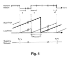
- FIG. 4 is a timeline depiction of the activities of a good node during steady state.
- FIG. 5 shows three inter-related blocks of pseudocode, representing implementations of the components of a self-stabilization protocol in accordance with one embodiment of the invention.
- FIG. 6 is a flow chart showing the interaction of coarse and fine level protocols in another embodiment of the invention.
- the present disclosure is primarily directed at one advantageous embodiment, with a number of suggested alternatives and extensions.
- the underlying topology considered is a network of K>3F+1 nodes that communicate by exchanging messages through a set of communication channels.
- a maximum of F Byzantine faulty nodes are assumed to be present in the system, where F>0.
- the Byzantine nodes may be modeled as nodes with arbitrary and/or malicious behavior that may influence other nodes at every clock tick and at all times,
- the communication channels are assumed to connect a set of source nodes to a set of destination nodes such that the source of a given message is distinctly identifiable from other sources of messages,
- K G represent the set of good nodes.
- the nodes communicate with each other by exchanging broadcast messages. Broadcast of a message to all other nodes is realized by transmitting the message to all other nodes at the same time.
- the source of a message is assumed to be uniquely identifiable.
- the communication network does not guarantee any relative order of arrival of a broadcast message at the receiving nodes.
- Kopetz Kopetz 1997
- a consistent delivery order of a set of messages does not necessarily reflect the temporal or causal order of the events.
- Each node is driven by an independent local physical oscillator.
- the oscillators of good nodes have a known bounded drift rate, 0 ⁇ 1, with respect to real time.
- 0 ⁇ 1 drift rate
- Each node has two primary logical time clocks, StateTimer and LocalTimer, which locally keep track of the passage of time as indicated by the physical oscillator.
- StateTimer and LocalTimer
- All references to clock synchronization and self-stabilization of the system are with respect to the StateTimer and the LocalTimer of the nodes.
- the communication channels and the nodes can behave arbitrarily, provided that eventually the system adheres to the system assumptions (see Section 2.5 below).
- FIG. 1 is a time line showing event-response delay, D, and network imprecision, d.
- the latency of interdependent communications between the nodes is expressed in terms of the minimum event-response delay, D, and network imprecision, d.
- a message transmitted by node N i at real time t 0 is expected to arrive at all destination nodes N j , be processed, and subsequent messages generated by N j within the time interval of [t 0 +D, t 0 +D+d] for all N j ⁇ K G .
- Communication between independently clocked nodes is inherently imprecise.
- the network imprecision, d is the maximum time difference between all good receivers, N j , of a message from N i with respect to real time.
- the imprecision is due to the drift of the clocks with respect to real time, jitter, discretization error, temperature effects and differences in the lengths of the physical communication medium.
- the time line is partitioned into a sequence of equally-spaced intervals measured by the local oscillator since the node transitioned into another state.
- Such an interval, ⁇ is expressed in terms of the minimum event-response delay, D, and network imprecision, d, and is constrained such that ⁇ (D+d), and is one or more local clock ticks. Therefore, the time-driven activities take place at equally-spaced intervals measured by the local oscillator since the node entered a new state. Unless stated otherwise, all time-dependent parameters of this protocol are measured locally and expressed as functions of ⁇ . In contrast, the event-driven activities are independent of ⁇ and, thus, take place immediately.
- the nodes communicate by exchanging a self-stabilization message labeled Sync.
- the Sync message is transmitted either as a result of a resynchronization timeout, or when a node determines that sufficient number of other nodes have engaged in the resynchronization process.
- the maximum number of faulty nodes, F, the minimum number of good nodes, G and the remaining parameters that are subsequently presented are derived parameters and are based on these fundamental parameters.
- One such derived parameter is ⁇ , and another is T R , which is used as a threshold in connection with the Sync messages.
- each node has a set of monitors and a state machine.
- FIG. 2 is a block diagram showing i th node, N i , with its monitors 201 etc. and state machine 202 (discussed in Section 2.3 below). Inputs 203 etc. come from other nodes, to each monitor, and output 204 goes to other nodes via broadcast.
- the messages to be delivered to the destination nodes are deposited on communication channels.
- a node employs (K ⁇ 1) monitors, one monitor for each source of incoming messages as shown in FIG. 2 .
- a node neither uses nor monitors its own messages.
- the distributed observation of other nodes localizes error detection of incoming messages to their corresponding monitors, and allows for modularization and distribution of the self-stabilization protocol process within a node.
- a monitor keeps track of the activities of its corresponding source node. Specifically, a monitor reads, evaluates, time stamps, validates, and stores only the last valid message it receives from that node.
- a monitor maintains a logical timer, MessageTimer, by incrementing it once per local clock tick. This timer is reset upon receiving a valid Sync message.
- a monitor also disposes retained valid messages as appropriate.
- FIG. 3 is a state transition diagram showing the node state machine.
- Edge 303 relates to when a Sync message received in the Restore state (the system stays in the Restore state as explained below, because transition out of the Restore state depends on meeting “transitory conditions”).
- Edge 304 is the transition from the Maintain state to the Restore state, showing a Sync message being sent in that event (as explained below).
- the assessment results of the monitored nodes are utilized by the node in the self-stabilization process.
- the node comprises a state machine and a set of (K ⁇ 1) monitors.
- the state machine has two states, Restore (R) and Maintain (M), that reflect the current state of the node in the system as shown in FIG. 3 .
- the state machine describes the behavior of the node, N i , utilizing assessment results from its monitors, M 1 . . . M i ⁇ 1 , M i+1 . . . M K as shown in FIG. 2 , where M j is the monitor for the corresponding node N i .
- a monitor's internal status is influenced by the current state of the node's state machine. When the state machine transitions to the Restore state the monitors update their internal status as appropriate.
- the transitory conditions enable the node to migrate from the Restore state to the Maintain state. Although during the self-stabilization process a node may also transition from the Restore state to the Maintain state upon a timeout, during steady state, such a time-out is indicative of an abnormal behavior. Therefore, the transitory conditions are defined with respect to the steady state where such time-outs do not occur.
- the transitory delay is the length of time a node stays in the Restore state.
- the minimum required duration for the transitory delay is denoted by TD min and the maximum duration of the transitory delay by TD max .
- the TD min is a derived parameter and a function of F. For the fully connected topology considered here, the transitory conditions are defined as follows.
- TD max The maximum duration of the transitory delay, TD max , is dependent on the number of additional valid Sync messages received and the drift rate ⁇ .
- the node In the Restore state, the node will either meet the transitory conditions and transition to the Maintain state, or remain in the Restore state for a predetermined maximum duration until it times out and then transition to the Maintain state. In the Maintain state, a node will either remain in the Maintain state for a predetermined maximum duration until it times out and transitions to the Restore state, or transition to the Restore state when T R other nodes have transitioned out of the Maintain state. The node transmits a Sync message when transitioning to the Restore state.
- FIG. 4 the transitions of a good node to the Restore state and then from the Restore state to the Maintain state (during steady state) are depicted along a timeline of activities of the node.
- a Sync message is transmitted as the node transitions from the Restore state to the Maintain state. Activities of the StateTimer and LocalTimer of the node as it transitions between different states are also depicted in this figure.
- the periodic synchronization during steady state is referred to as the resynchronization process, whereby all good nodes transition to the Restore state and then synchronously to the Maintain state.
- the resynchronization process begins when the first good node transitions to the Restore state and ends after the last good node transitions to the Maintain state.
- the synchronization period is defined as the maximum time interval (during steady state) that a good node engages in the resynchronization process.
- the synchronization period depends on the maximum durations of both states of the node's state machine.
- the maximum duration for the Restore state is denoted by P R
- the maximum duration for the Maintain state is denoted by P M , where P R and P M are expressed in terms of ⁇ .
- the length of time a good node stays in the Restore state is denoted by L R .
- L R is always less than P R .
- the length of time a good node stays in the Maintain state is denoted by L M .
- ⁇ SS The time interval between any two consecutive Sync messages from a node.
- ⁇ SS,min The shortest such interval.
- ⁇ SS,min (TD min ⁇ +1) clock ticks.
- a node keeps track of time by incrementing its logical time clock StateTimer once every ⁇ . After the StateTimer reaches P R or P M depending on the current state of the node, the node times out, resets the StateTimer, and transitions to the other state. If the node was in the Maintain state it transmits a new Sync message, The current value of this timer reflects the duration of the current state of the node.
- This protocol does not maintain a history of past behavior of the nodes. All such determinations about the health status of the nodes in the system are assumed to be done by higher level mechanisms.
- This protocol is expected to be used as the fundamental mechanism in bringing and maintaining a system within a known synchronization precision bound. Therefore, the protocol has to properly filter out inherent oscillations in the StateTimer during the resynchronization process as depicted in FIG. 4 .
- This issue is resolved by using the LocalTimer in the protocol.
- the logical time clock LocalTimer is incremented once every local clock tick and is reset either when it reaches its maximum allowed value or when the node has transitioned to the Maintain state and remained in that state for ResetLocalTimerAt local clock ticks, where ResetLocalTimerAt is constrained by the following inequality: ⁇ Precision / ⁇ ResetLocalTimerAt ⁇ P M ⁇ Precision / ⁇ (1)
- the LocalTimer is intended to be used by higher level protocols and must be managed properly to provide the desired behavior.
- InvalidSync( ) is used by the monitors. This function determines whether a received Sync message is invalid. When this function returns a true value, it indicates that an unexpected behavior by the corresponding source node has been detected.
- the function ConsumeMessage( ) is used by the monitors.
- the monitor invalidates the stored Sync message after it has been kept for ⁇ .
- the TransitoryConditionsMet( ) function determines proper timing of the transition from the Restore state to the Maintain state. This function keeps track of the passage of time by monitoring StateTimer and determines if the node has been in the Restore state for at least TD min . It returns a true value when the transitory conditions are met.
- the TimeOutRestore( ) function uses P R as a boundary value and asserts a timeout condition when the value of the StateTimer has reached P R . Such timeout triggers the node to transition to the Maintain state.
- the TimeOutMaintain( ) function uses P M as a boundary value and asserts a timeout condition when the value of the StateTimer has reached P M . Such timeout triggers the node to reengage in another round of synchronization. This function is used when the node is in the Maintain state.
- the state machine utilizes the TimeoutGammaTimer( ) function.
- This function is used to regulate node activities at the ⁇ boundaries. It maintains a GammaTimer by incrementing it once per local clock tick and once it reaches the duration of ⁇ , it is reset and the function returns a true value.
- a good node N i resets its variable LocalTimer i periodically but at different points in time than other good nodes.
- the difference of local timers of all good nodes at time t, ⁇ LocalTimer (t), is determined by the following equation while recognizing the variations in the values of the LocalTimer i across all good nodes.
- ⁇ LocalTimer ( t ) min((LocalTimer max ( t ) ⁇ LocalTimer min ( t )), (LocalTimer max ( t ⁇ r ) ⁇ LocalTimer min ( t ⁇ r ))), where,
- the presented protocol is described in FIG. 5 and comprises a state machine and a set of monitors that execute once every local oscillator tick.
- the protocol steps are:
- the protocol steps are:
- P R In general, and for all F>0 and K ⁇ 3F+1, and to prevent an early timeout, P R must be constrained in accordance with the previous paragraph.
- the maximum duration for the Maintain state, P M is typically much larger than P R .
- P M is derived to be P M ⁇ P R .
- a model of this protocol has been mechanically verified using the SMV state machine language where the entire state space is examined, and proven to self-stabilize in the presence of one arbitrary faulty node.
- the self-stabilizing protocol disclosed herein has many practical applications. Embedded systems, distributed process control, synchronization, inherent fault tolerance which also includes Byzantine agreement, computer networks, the Internet, Internet applications, security, safety, automotive, aircraft, wired and wireless telecommunications, graph theoretic problems, leader election, and time division multiple access (TDMA), are a few examples. These are some of the many areas of distributed systems that can use self-stabilization in order to design more robust distributed systems.
- TDMA time division multiple access
- the system Since the time-driven self-stabilization activities take place at ⁇ intervals, if ⁇ , and hence ⁇ Precision , are larger than the desired precision, the system is said to be coarsely synchronized. Otherwise, the system is said to be finely synchronized. If the granularity provided by the self-stabilization precision is coarser than desired, a higher synchronization precision can be achieved in a two step process. First, a system from any initial state has to be coarsely synchronized and guaranteed that the system remains coarsely synchronized and operates within a known precision, ⁇ Precision . The second step, in conjunction with the coarse synchronization protocol, is to utilize a proven protocol that is based on the initial synchrony assumptions to achieve optimum precision of the synchronized system as depicted in FIG. 6 .
- the coarse synchronization protocol 601 initiates the start of the fine synchronization protocol 603 if a tighter precision of the system is desired ( 602 ).
- the coarse synchronization protocol maintains self-stabilization of the system while the fine synchronization protocol increases the precision of the system.
- the necessary conditions to initiate the fine synchronization protocol are that convergence has to be achieved and all good nodes have to be in the Maintain state. It follows from Theorem Congruence that upon convergence all good nodes are in the Maintain state. Thus, examination of the current state as well as the value of the StateTimer of the good nodes provides the necessary conditions to attempt to initiate the fine synchronization protocol.
Abstract
Description
-
- A Sync message from a given source is valid if it arrives at or after ΔSS,min of its previous valid Sync message.
- While in the Maintain state, a Sync message from a given source remains valid for the duration of that state.
- While in the Restore state, a Sync message from a given source remains valid for the duration of one γ.
-
- 1. The node has remained in the Restore state for at least TDmin since it entered the Restore state, where
- TDmin=2, for F=0, or
- TDmin=2F, for F>0, and
- 2. One γ has passed since the arrival of the last validSync message.
- 1. The node has remained in the Restore state for at least TDmin since it entered the Restore state, where
┌ΔPrecision/γ┐≦ResetLocalTimerAt≦P M−┌ΔPrecision/γ┐ (1)
-
- 1. The cause of transient faults has dissipated.
- 2. All good nodes actively participate in the self-stabilization process and correctly execute the protocol.
- 3. At most F of the nodes remain faulty.
- 4. The source of a message is distinctly identifiable by the receivers from other sources of messages.
- 5. A message sent by a good node will be received and processed by all other good nodes within γ, where γ≧(D+d).
- 6. The initial values of the state and all variables of a node can be set to any arbitrary value within their corresponding range. (In an implementation, it is expected that some local capabilities exist to enforce type consistency for all variables.)
-
- C be the bound on the maximum convergence time,
- ΔLocalTimer(t), for real time t, be the maximum difference of values of the local timers of any two good nodes Ni and Nj, where Ni, NjεKG, and KG is the set of all good nodes, and
- ΔPrecision, also referred to as self-stabilization or synchronization precision, be the guaranteed upper bound on the maximum separation between the local timers of any two good nodes Ni and Nj in the presence of a maximum of F faulty nodes, where Ni, NjεKG.
ΔLocalTimer(t)=min((LocalTimermax(t)−LocalTimermin(t)), (LocalTimermax(t−r)−LocalTimermin(t−r))),
where,
-
- 1. Convergence: ΔLocalTimer(t)≦ΔPrecision
- 2. Closure: ∀t≧C, ΔLocalTimer(t)≦ΔPrecision
- 3. Congruence: ∀Ni, NjεKG, ∀t≧C, LocalTimeri(t)=0→Ni and Nj are in the Maintain state.
C=(2P R +P M)·γ
ΔPrecision=(3F−1)·γ−D+Δ Drift,
P=P R +P M,
P M >>P R,
where the amount of drift from the initial precision is given by
ΔDrift((1+ρ)−1/(1+ρ))P·γ.
-
- Indentation is used to show a block of sequential statements.
- Commas (,) are used to separate sequential statements.
- A period (.) is used to end a statement.
- A period combined with a comma (.,) is used to mark the end of a statement and at the same time to separate it from other sequential statements.
-
- 1. if there is an incoming message from the node corresponding to the monitor:
- (a) determining if the message is a valid Sync message;
- (b) if the message is a valid Sync message, validating and storing the message;
- (c) if the message is not a valid Sync message, invalidating the message;
- 2. otherwise, if there is no such message, doing nothing
- 1. if there is an incoming message from the node corresponding to the monitor:
-
- 1. determining if the node has timed out in the Restore state;
- 2. if the node has timed out in the Restore state,
- resetting the StateTimer; and
- changing the machine state for the node to the Maintain state;
- 3. if the node has not timed out in the Restore state,
- determining if transitory conditions are met (i.e., that (a) the node has remained in the Restore state, since last entering that state, for a period equal to or greater than two StateTimer ticks, where the number of said faulty nodes is zero, or two times the number of faulty nodes, where the number of faulty nodes is greater than zero, and (b) a period of at least one γ has passed since the arrival of the last valid Sync message);
- if the transitory conditions are met,
- resetting the StateTimer;
- changing the machine state for the node to the Maintain state;
- if the transitory conditions are not met,
- keeping the machine state for the node in the Restore state;
- 4. else (if the node has not timed out in the Restore state),
- keeping the machine state for the node in the Restore state;
-
- 1. if either (a) the StateTimer has exceeded PM, or (b) the number of valid Sync messages received from other nodes is at least one more than the number of faulty nodes,
- (i) broadcasting a Sync message to all of said other nodes;
- (ii) resetting the StateTimer clock;
- (iii) changing the machine state for the node to the Restore state;
- 2. else (if neither (a) the StateTimer has exceeded PM, nor (b) the number of valid Sync messages received from other nodes is at least one more than the number of faulty nodes, and (c) the GammaTimer clock has reached the duration of γ),
- (a) if the value of the StateTimer clock equals ┌ΔPrecision/γ┐, resetting said LocalTimer clock;
- (b) keeping the machine state for the node in the Maintain state;
- 3. else (if neither (a) the StateTimer has exceeded a predetermined maximum interval, nor (b) the number of valid Sync messages received from other nodes is at least one more than the number of faulty nodes, and (c) the GammaTimer clock has not reached the duration of γ),
- keeping the machine state for the node in the Maintain state.
- 1. if either (a) the StateTimer has exceeded PM, or (b) the number of valid Sync messages received from other nodes is at least one more than the number of faulty nodes,
If 0≦ΔDrift <D,
PR>7F−1.
If ΔDrift =D,
PR>7F+1.
If 2D>Δ Drift >D,
PR>7F+3.
| Symbols | Description |
| ρ | bounded drift rate with respect to real time |
| d | network imprecision |
| D | event-response delay |
| F | maximum number of faulty nodes |
| G | minimum number of good nodes |
| K | sum of all nodes |
| KG | set of all good nodes |
| Sync | self-stabilization message |
| S | abbreviation for Sync message |
| ΔSS | time difference between the last consecutive Sync |
| messages | |
| TR | threshold for Retry( ) function |
| Restore | self-stabilization state |
| Maintain | self-stabilization state |
| R | abbreviation for Restore state |
| M | abbreviation for Maintain state |
| PR | maximum duration while in the Restore state |
| PR, min | minimum value of PR |
| PM | maximum duration while in the Maintain state |
| PActual | effective synchronization period |
| ν | equal space time intervals for time-driven |
| activities | |
| C | maximum convergence time |
| ΔLocalTimer(t) | maximum time difference of LocalTimers of any two |
| good nodes at real time t | |
| LM | Latest Maintain |
| EM | Earliest Maintain |
| ΔLMEM | difference of LM and EM, initial self-stabilization |
| precision | |
| ΔPrecision | maximum self-stabilization precision |
| ΔDrift | maximum deviation from the initial synchrony |
| Ni | the ith node |
| Mi | the ith monitor of a node |
Claims (34)
(3F−1)·γ−D+Δ Drift.
Priority Applications (1)
| Application Number | Priority Date | Filing Date | Title |
|---|---|---|---|
| US12/429,603 US8255732B2 (en) | 2008-05-28 | 2009-04-24 | Self-stabilizing byzantine-fault-tolerant clock synchronization system and method |
Applications Claiming Priority (2)
| Application Number | Priority Date | Filing Date | Title |
|---|---|---|---|
| US5653708P | 2008-05-28 | 2008-05-28 | |
| US12/429,603 US8255732B2 (en) | 2008-05-28 | 2009-04-24 | Self-stabilizing byzantine-fault-tolerant clock synchronization system and method |
Publications (2)
| Publication Number | Publication Date |
|---|---|
| US20100019811A1 US20100019811A1 (en) | 2010-01-28 |
| US8255732B2 true US8255732B2 (en) | 2012-08-28 |
Family
ID=41568085
Family Applications (1)
| Application Number | Title | Priority Date | Filing Date |
|---|---|---|---|
| US12/429,603 Expired - Fee Related US8255732B2 (en) | 2008-05-28 | 2009-04-24 | Self-stabilizing byzantine-fault-tolerant clock synchronization system and method |
Country Status (1)
| Country | Link |
|---|---|
| US (1) | US8255732B2 (en) |
Cited By (3)
| Publication number | Priority date | Publication date | Assignee | Title |
|---|---|---|---|---|
| US20120207258A1 (en) * | 2011-02-15 | 2012-08-16 | U.S.A. As Represented By The Administrator Of The National Aeronautics And Space Administration | Fault-Tolerant Self-Stabilizing Distributed Clock Synchronization Protocol for Arbitrary Digraphs |
| US10025344B2 (en) | 2015-04-21 | 2018-07-17 | The United States Of America As Represented By The Administrator Of Nasa | Self-stabilizing distributed symmetric-fault tolerant synchronization protocol |
| US10736062B2 (en) | 2017-05-09 | 2020-08-04 | United States Of America As Represented By The Administrator Of Nasa | System and method to synchronize clocks across a distributed network of nodes |
Families Citing this family (4)
| Publication number | Priority date | Publication date | Assignee | Title |
|---|---|---|---|---|
| US8909509B2 (en) | 2010-10-01 | 2014-12-09 | Rockwell Automation Technologies, Inc. | Dynamically selecting master clock to manage non-linear simulation clocks |
| DE102017210895A1 (en) | 2017-06-28 | 2019-01-03 | Bayerische Motoren Werke Aktiengesellschaft | A method, computer readable medium, system, and vehicle comprising the system for validating a time function of a master and the clients in a network of a vehicle |
| US11353918B2 (en) | 2018-09-26 | 2022-06-07 | The Charles Stark Draper Laboratory, Inc. | Asynchronous timing exchange for redundant clock synchronization |
| CN114003530B (en) * | 2021-10-29 | 2023-04-11 | 上海大学 | FPGA-based serial differential communication data acquisition system and method |
Citations (30)
| Publication number | Priority date | Publication date | Assignee | Title |
|---|---|---|---|---|
| US4866606A (en) | 1984-06-22 | 1989-09-12 | Austria Miktosystem International Gmbh | Loosely coupled distributed computer system with node synchronization for precision in real time applications |
| US4979191A (en) | 1989-05-17 | 1990-12-18 | The Boeing Company | Autonomous N-modular redundant fault tolerant clock system |
| US4984241A (en) | 1989-01-23 | 1991-01-08 | The Boeing Company | Tightly synchronized fault tolerant clock |
| US5041966A (en) * | 1987-10-06 | 1991-08-20 | Nec Corporation | Partially distributed method for clock synchronization |
| US5249206A (en) | 1989-08-11 | 1993-09-28 | International Business Machines Corporation | Fault-tolerant clock for multicomputer complex |
| US5295257A (en) | 1991-05-24 | 1994-03-15 | Alliedsignal Inc. | Distributed multiple clock system and a method for the synchronization of a distributed multiple system |
| US5377205A (en) | 1993-04-15 | 1994-12-27 | The Boeing Company | Fault tolerant clock with synchronized reset |
| US5377206A (en) | 1993-02-03 | 1994-12-27 | Honeywell Inc. | Multiple-channel fault-tolerant clock system |
| US5557623A (en) | 1994-08-12 | 1996-09-17 | Honeywell Inc. | Accurate digital fault tolerant clock |
| US5600784A (en) | 1993-12-01 | 1997-02-04 | Marathon Technologies Corporation | Fault resilient/fault tolerant computing |
| US5907685A (en) | 1995-08-04 | 1999-05-25 | Microsoft Corporation | System and method for synchronizing clocks in distributed computer nodes |
| US5964846A (en) | 1997-07-07 | 1999-10-12 | International Business Machines Corporation | System and method for mapping processor clock values in a multiprocessor system |
| US6178522B1 (en) | 1998-06-02 | 2001-01-23 | Alliedsignal Inc. | Method and apparatus for managing redundant computer-based systems for fault tolerant computing |
| US6349391B1 (en) | 1996-05-16 | 2002-02-19 | Resilience Corporation | Redundant clock system and method for use in a computer |
| US20020129087A1 (en) | 2000-01-13 | 2002-09-12 | International Business Machines Corporation | Agreement and atomic broadcast in asynchronous networks |
| US6567927B1 (en) | 1999-05-07 | 2003-05-20 | Daimlerchrysler Aerospace Ag | Logic unit operable under the byzantine algorithm, computer unit having such logic unit, composite assembly comprised of logic units or computer units, and method of operating such an assembly |
| US6671821B1 (en) | 1999-11-22 | 2003-12-30 | Massachusetts Institute Of Technology | Byzantine fault tolerance |
| US20040205372A1 (en) | 2003-01-03 | 2004-10-14 | Eternal Systems, Inc. | Consistent time service for fault-tolerant distributed systems |
| US20050089131A1 (en) | 2003-10-23 | 2005-04-28 | Microsoft Corporation | Byzantine fault quantifying clock synchronization |
| US7023884B2 (en) | 2000-12-19 | 2006-04-04 | Lucent Technologies Inc. | Clock offset estimation with bias correction |
| US20060109868A1 (en) | 2004-10-27 | 2006-05-25 | Siemens Ag | Method and system for time synchronisation in a distributed communications network |
| US7124316B2 (en) | 2000-10-10 | 2006-10-17 | Fts Computertechnik Ges M.B.H. | Handling errors in an error-tolerant distributed computer system |
| US7257133B2 (en) | 2002-09-30 | 2007-08-14 | Lucent Technologies Inc. | Method for estimating offset for clocks at network elements |
| US7260652B2 (en) | 2000-12-28 | 2007-08-21 | Robert Bosch Gmbh | Method and communication system for exchanging data between at least two stations via a bus system |
| US7263630B2 (en) | 2003-01-23 | 2007-08-28 | Supercomputing System Ag | Fault tolerant computer controlled system |
| US7328235B2 (en) | 2001-03-23 | 2008-02-05 | Ihi Aerospace Co., Ltd. | Multiple processing method |
| US7509513B2 (en) * | 2001-01-16 | 2009-03-24 | Thales | Fault-tolerant synchronisation device for a real-time computer network |
| US7792015B2 (en) * | 2007-08-09 | 2010-09-07 | United States Of America As Represented By The Administrator Of The National Aeronautics And Space Administration | Byzantine-fault tolerant self-stabilizing protocol for distributed clock synchronization systems |
| US7912094B2 (en) * | 2006-12-13 | 2011-03-22 | Honeywell International Inc. | Self-checking pair-based master/follower clock synchronization |
| US7991101B2 (en) * | 2006-12-20 | 2011-08-02 | Broadcom Corporation | Multiple channel synchronized clock generation scheme |
-
2009
- 2009-04-24 US US12/429,603 patent/US8255732B2/en not_active Expired - Fee Related
Patent Citations (31)
| Publication number | Priority date | Publication date | Assignee | Title |
|---|---|---|---|---|
| US4866606A (en) | 1984-06-22 | 1989-09-12 | Austria Miktosystem International Gmbh | Loosely coupled distributed computer system with node synchronization for precision in real time applications |
| US5041966A (en) * | 1987-10-06 | 1991-08-20 | Nec Corporation | Partially distributed method for clock synchronization |
| US4984241A (en) | 1989-01-23 | 1991-01-08 | The Boeing Company | Tightly synchronized fault tolerant clock |
| US4979191A (en) | 1989-05-17 | 1990-12-18 | The Boeing Company | Autonomous N-modular redundant fault tolerant clock system |
| US5249206A (en) | 1989-08-11 | 1993-09-28 | International Business Machines Corporation | Fault-tolerant clock for multicomputer complex |
| US5295257A (en) | 1991-05-24 | 1994-03-15 | Alliedsignal Inc. | Distributed multiple clock system and a method for the synchronization of a distributed multiple system |
| US5377206A (en) | 1993-02-03 | 1994-12-27 | Honeywell Inc. | Multiple-channel fault-tolerant clock system |
| US5377205A (en) | 1993-04-15 | 1994-12-27 | The Boeing Company | Fault tolerant clock with synchronized reset |
| US5600784A (en) | 1993-12-01 | 1997-02-04 | Marathon Technologies Corporation | Fault resilient/fault tolerant computing |
| US5956474A (en) | 1993-12-01 | 1999-09-21 | Marathon Technologies Corporation | Fault resilient/fault tolerant computing |
| US5557623A (en) | 1994-08-12 | 1996-09-17 | Honeywell Inc. | Accurate digital fault tolerant clock |
| US5907685A (en) | 1995-08-04 | 1999-05-25 | Microsoft Corporation | System and method for synchronizing clocks in distributed computer nodes |
| US6349391B1 (en) | 1996-05-16 | 2002-02-19 | Resilience Corporation | Redundant clock system and method for use in a computer |
| US5964846A (en) | 1997-07-07 | 1999-10-12 | International Business Machines Corporation | System and method for mapping processor clock values in a multiprocessor system |
| US6178522B1 (en) | 1998-06-02 | 2001-01-23 | Alliedsignal Inc. | Method and apparatus for managing redundant computer-based systems for fault tolerant computing |
| US6567927B1 (en) | 1999-05-07 | 2003-05-20 | Daimlerchrysler Aerospace Ag | Logic unit operable under the byzantine algorithm, computer unit having such logic unit, composite assembly comprised of logic units or computer units, and method of operating such an assembly |
| US6671821B1 (en) | 1999-11-22 | 2003-12-30 | Massachusetts Institute Of Technology | Byzantine fault tolerance |
| US20020129087A1 (en) | 2000-01-13 | 2002-09-12 | International Business Machines Corporation | Agreement and atomic broadcast in asynchronous networks |
| US7124316B2 (en) | 2000-10-10 | 2006-10-17 | Fts Computertechnik Ges M.B.H. | Handling errors in an error-tolerant distributed computer system |
| US7023884B2 (en) | 2000-12-19 | 2006-04-04 | Lucent Technologies Inc. | Clock offset estimation with bias correction |
| US7260652B2 (en) | 2000-12-28 | 2007-08-21 | Robert Bosch Gmbh | Method and communication system for exchanging data between at least two stations via a bus system |
| US7509513B2 (en) * | 2001-01-16 | 2009-03-24 | Thales | Fault-tolerant synchronisation device for a real-time computer network |
| US7328235B2 (en) | 2001-03-23 | 2008-02-05 | Ihi Aerospace Co., Ltd. | Multiple processing method |
| US7257133B2 (en) | 2002-09-30 | 2007-08-14 | Lucent Technologies Inc. | Method for estimating offset for clocks at network elements |
| US20040205372A1 (en) | 2003-01-03 | 2004-10-14 | Eternal Systems, Inc. | Consistent time service for fault-tolerant distributed systems |
| US7263630B2 (en) | 2003-01-23 | 2007-08-28 | Supercomputing System Ag | Fault tolerant computer controlled system |
| US20050089131A1 (en) | 2003-10-23 | 2005-04-28 | Microsoft Corporation | Byzantine fault quantifying clock synchronization |
| US20060109868A1 (en) | 2004-10-27 | 2006-05-25 | Siemens Ag | Method and system for time synchronisation in a distributed communications network |
| US7912094B2 (en) * | 2006-12-13 | 2011-03-22 | Honeywell International Inc. | Self-checking pair-based master/follower clock synchronization |
| US7991101B2 (en) * | 2006-12-20 | 2011-08-02 | Broadcom Corporation | Multiple channel synchronized clock generation scheme |
| US7792015B2 (en) * | 2007-08-09 | 2010-09-07 | United States Of America As Represented By The Administrator Of The National Aeronautics And Space Administration | Byzantine-fault tolerant self-stabilizing protocol for distributed clock synchronization systems |
Non-Patent Citations (4)
| Title |
|---|
| H. Koptez. "Real-Time Systems. Design Principles for Distributed Embedded Applications," 1997, p. 47 Kluwer Academic Publishers, United States of America. |
| Mahyar R. Malekpour, "A Self-Stabilizing Byzantine-Fault-Tolerant Clock Synchronization Protocol", NASA LaRC Abstract, May 23, 2008, pp. 1-14. |
| Mahyar R. Malekpour, "A Self-Stabilizing Byzantine-Fault-Tolerant Clock Synchronization Protocol", NASA LaRC Abstract, Nov. 28, 2007, pp. 1-14. |
| Mahyar R. Malekpour, "A Self-Stabilizing Byzantine-Fault-Tolerant Clock Synchronization Protocol", NASA TM-2008, Jan. 2008, pp. 1-42. |
Cited By (4)
| Publication number | Priority date | Publication date | Assignee | Title |
|---|---|---|---|---|
| US20120207258A1 (en) * | 2011-02-15 | 2012-08-16 | U.S.A. As Represented By The Administrator Of The National Aeronautics And Space Administration | Fault-Tolerant Self-Stabilizing Distributed Clock Synchronization Protocol for Arbitrary Digraphs |
| US8861552B2 (en) * | 2011-02-15 | 2014-10-14 | The United States Of America As Represented By The Administrator Of The National Aeronautics And Space Administration | Fault-tolerant self-stabilizing distributed clock synchronization protocol for arbitrary digraphs |
| US10025344B2 (en) | 2015-04-21 | 2018-07-17 | The United States Of America As Represented By The Administrator Of Nasa | Self-stabilizing distributed symmetric-fault tolerant synchronization protocol |
| US10736062B2 (en) | 2017-05-09 | 2020-08-04 | United States Of America As Represented By The Administrator Of Nasa | System and method to synchronize clocks across a distributed network of nodes |
Also Published As
| Publication number | Publication date |
|---|---|
| US20100019811A1 (en) | 2010-01-28 |
Similar Documents
| Publication | Publication Date | Title |
|---|---|---|
| US8255732B2 (en) | Self-stabilizing byzantine-fault-tolerant clock synchronization system and method | |
| KR101426325B1 (en) | Network element for a packet-switched network | |
| JP5370870B2 (en) | Method for synchronizing to a local clock in a distributed computer network | |
| US9491106B2 (en) | Non-intrusive method for synchronizing master and slave clocks of a packet-switched network, and associated synchronization devices | |
| US10025344B2 (en) | Self-stabilizing distributed symmetric-fault tolerant synchronization protocol | |
| EP2738971A1 (en) | Mehtod and device for clock synchronization | |
| US7792015B2 (en) | Byzantine-fault tolerant self-stabilizing protocol for distributed clock synchronization systems | |
| CN108282243B (en) | A kind of clock source reliability guarantee method suitable for master-slave mode method for synchronizing time | |
| CN108259109B (en) | Network equipment in PTP domain and TOD synchronization method | |
| US10038547B2 (en) | Method for synchronising a server cluster and server cluster implementing said method | |
| US8463945B2 (en) | Method for synchronizing local clocks in a distributed computer network | |
| Malekpour | A byzantine-fault tolerant self-stabilizing protocol for distributed clock synchronization systems | |
| Ferreira et al. | Combining operational flexibility and dependability in FTT-CAN | |
| US8861552B2 (en) | Fault-tolerant self-stabilizing distributed clock synchronization protocol for arbitrary digraphs | |
| Kopetz et al. | Integration of internal and external clock synchronization by the combination of clock-state and clock-rate correction in fault-tolerant distributed systems | |
| D'Amato et al. | Improving asynchrony resilience in dynamically available total-order broadcast protocols | |
| Malekpour | A self-stabilizing hybrid fault-tolerant synchronization protocol | |
| Rahman et al. | Delay asymmetry correction model for master-slave synchronization protocols | |
| Boulanger et al. | A time synchronization protocol for A664-P7 | |
| Malekpour | A self-stabilizing Byzantine-fault-tolerant clock synchronization protocol | |
| CN105323086A (en) | Synchronization time source selection indication method, device and system | |
| Malekpour | Verification of a byzantine-fault-tolerant self-stabilizing protocol for clock synchronization | |
| Hanzlik et al. | A composable algorithm for clock synchronization in multi-cluster real-time systems | |
| Mathiesen et al. | Clock Synchronisation Method Over Bandwidth-Limited CAN-Bus | |
| Malekpour | Achieving Agreement In Three Rounds With Bounded-Byzantine Faults |
Legal Events
| Date | Code | Title | Description |
|---|---|---|---|
| AS | Assignment |
Owner name: UNITED STATES OF AMERICA AS REPRESENTED BY THE ADM Free format text: ASSIGNMENT OF ASSIGNORS INTEREST;ASSIGNOR:MALEKPOUR, MAHYAR R.;REEL/FRAME:022733/0415 Effective date: 20090224 |
|
| STCF | Information on status: patent grant |
Free format text: PATENTED CASE |
|
| FPAY | Fee payment |
Year of fee payment: 4 |
|
| FEPP | Fee payment procedure |
Free format text: MAINTENANCE FEE REMINDER MAILED (ORIGINAL EVENT CODE: REM.); ENTITY STATUS OF PATENT OWNER: LARGE ENTITY |
|
| LAPS | Lapse for failure to pay maintenance fees |
Free format text: PATENT EXPIRED FOR FAILURE TO PAY MAINTENANCE FEES (ORIGINAL EVENT CODE: EXP.); ENTITY STATUS OF PATENT OWNER: LARGE ENTITY |
|
| STCH | Information on status: patent discontinuation |
Free format text: PATENT EXPIRED DUE TO NONPAYMENT OF MAINTENANCE FEES UNDER 37 CFR 1.362 |
|
| FP | Lapsed due to failure to pay maintenance fee |
Effective date: 20200828 |