US8253336B2 - LED lamp for producing biologically-corrected light - Google Patents
LED lamp for producing biologically-corrected light Download PDFInfo
- Publication number
- US8253336B2 US8253336B2 US12/842,887 US84288710A US8253336B2 US 8253336 B2 US8253336 B2 US 8253336B2 US 84288710 A US84288710 A US 84288710A US 8253336 B2 US8253336 B2 US 8253336B2
- Authority
- US
- United States
- Prior art keywords
- led chips
- lamp
- housing
- color filter
- driver circuit
- Prior art date
- Legal status (The legal status is an assumption and is not a legal conclusion. Google has not performed a legal analysis and makes no representation as to the accuracy of the status listed.)
- Active, expires
Links
- 230000003595 spectral effect Effects 0.000 claims abstract description 43
- YJPIGAIKUZMOQA-UHFFFAOYSA-N Melatonin Natural products COC1=CC=C2N(C(C)=O)C=C(CCN)C2=C1 YJPIGAIKUZMOQA-UHFFFAOYSA-N 0.000 claims abstract description 39
- 229960003987 melatonin Drugs 0.000 claims abstract description 39
- DRLFMBDRBRZALE-UHFFFAOYSA-N melatonin Chemical compound COC1=CC=C2NC=C(CCNC(C)=O)C2=C1 DRLFMBDRBRZALE-UHFFFAOYSA-N 0.000 claims abstract description 39
- 230000001629 suppression Effects 0.000 claims abstract description 26
- 230000004071 biological effect Effects 0.000 claims abstract description 23
- 238000000034 method Methods 0.000 claims abstract description 16
- 230000005540 biological transmission Effects 0.000 claims description 40
- 238000009877 rendering Methods 0.000 claims description 19
- 230000000694 effects Effects 0.000 claims description 14
- 238000009826 distribution Methods 0.000 claims description 7
- 229920006267 polyester film Polymers 0.000 claims description 6
- -1 polyethylene terephthalate Polymers 0.000 claims description 4
- 229920000139 polyethylene terephthalate Polymers 0.000 claims description 4
- 239000005020 polyethylene terephthalate Substances 0.000 claims description 4
- 239000000758 substrate Substances 0.000 claims description 4
- 239000000049 pigment Substances 0.000 claims description 2
- 238000004519 manufacturing process Methods 0.000 abstract description 4
- 238000001228 spectrum Methods 0.000 description 11
- ZDDZPDTVCZLFFC-UHFFFAOYSA-N 1,2,4,5-tetrachloro-3-(4-chlorophenyl)benzene Chemical compound C1=CC(Cl)=CC=C1C1=C(Cl)C(Cl)=CC(Cl)=C1Cl ZDDZPDTVCZLFFC-UHFFFAOYSA-N 0.000 description 7
- 230000027288 circadian rhythm Effects 0.000 description 6
- 238000001720 action spectrum Methods 0.000 description 4
- 230000002060 circadian Effects 0.000 description 4
- 208000019116 sleep disease Diseases 0.000 description 4
- 239000004020 conductor Substances 0.000 description 3
- 230000006870 function Effects 0.000 description 3
- 238000012986 modification Methods 0.000 description 3
- 230000004048 modification Effects 0.000 description 3
- 230000004044 response Effects 0.000 description 3
- RYGMFSIKBFXOCR-UHFFFAOYSA-N Copper Chemical compound [Cu] RYGMFSIKBFXOCR-UHFFFAOYSA-N 0.000 description 2
- OAICVXFJPJFONN-UHFFFAOYSA-N Phosphorus Chemical compound [P] OAICVXFJPJFONN-UHFFFAOYSA-N 0.000 description 2
- 229910052782 aluminium Inorganic materials 0.000 description 2
- XAGFODPZIPBFFR-UHFFFAOYSA-N aluminium Chemical compound [Al] XAGFODPZIPBFFR-UHFFFAOYSA-N 0.000 description 2
- JNDMLEXHDPKVFC-UHFFFAOYSA-N aluminum;oxygen(2-);yttrium(3+) Chemical compound [O-2].[O-2].[O-2].[Al+3].[Y+3] JNDMLEXHDPKVFC-UHFFFAOYSA-N 0.000 description 2
- 238000000576 coating method Methods 0.000 description 2
- 229910052802 copper Inorganic materials 0.000 description 2
- 239000010949 copper Substances 0.000 description 2
- 229940088597 hormone Drugs 0.000 description 2
- 239000005556 hormone Substances 0.000 description 2
- 238000004806 packaging method and process Methods 0.000 description 2
- 230000008569 process Effects 0.000 description 2
- 239000002096 quantum dot Substances 0.000 description 2
- 230000028327 secretion Effects 0.000 description 2
- 230000000007 visual effect Effects 0.000 description 2
- 229910019901 yttrium aluminum garnet Inorganic materials 0.000 description 2
- 206010006187 Breast cancer Diseases 0.000 description 1
- 208000026310 Breast neoplasm Diseases 0.000 description 1
- 208000017164 Chronobiology disease Diseases 0.000 description 1
- 206010010904 Convulsion Diseases 0.000 description 1
- 206010019233 Headaches Diseases 0.000 description 1
- 206010020772 Hypertension Diseases 0.000 description 1
- 206010028980 Neoplasm Diseases 0.000 description 1
- BPQQTUXANYXVAA-UHFFFAOYSA-N Orthosilicate Chemical compound [O-][Si]([O-])([O-])[O-] BPQQTUXANYXVAA-UHFFFAOYSA-N 0.000 description 1
- BQCADISMDOOEFD-UHFFFAOYSA-N Silver Chemical compound [Ag] BQCADISMDOOEFD-UHFFFAOYSA-N 0.000 description 1
- 229910000831 Steel Inorganic materials 0.000 description 1
- 239000000956 alloy Substances 0.000 description 1
- 229910045601 alloy Inorganic materials 0.000 description 1
- 230000008901 benefit Effects 0.000 description 1
- 201000011510 cancer Diseases 0.000 description 1
- 230000003915 cell function Effects 0.000 description 1
- 230000001413 cellular effect Effects 0.000 description 1
- 230000008859 change Effects 0.000 description 1
- 239000011248 coating agent Substances 0.000 description 1
- 150000001875 compounds Chemical class 0.000 description 1
- 230000001419 dependent effect Effects 0.000 description 1
- 206010012601 diabetes mellitus Diseases 0.000 description 1
- 239000010408 film Substances 0.000 description 1
- 239000002223 garnet Substances 0.000 description 1
- PCHJSUWPFVWCPO-UHFFFAOYSA-N gold Chemical compound [Au] PCHJSUWPFVWCPO-UHFFFAOYSA-N 0.000 description 1
- 229910052737 gold Inorganic materials 0.000 description 1
- 239000010931 gold Substances 0.000 description 1
- 231100000869 headache Toxicity 0.000 description 1
- 208000019622 heart disease Diseases 0.000 description 1
- 238000009413 insulation Methods 0.000 description 1
- 230000035772 mutation Effects 0.000 description 1
- 239000002245 particle Substances 0.000 description 1
- 210000004560 pineal gland Anatomy 0.000 description 1
- 239000004033 plastic Substances 0.000 description 1
- 229920003023 plastic Polymers 0.000 description 1
- 229920006289 polycarbonate film Polymers 0.000 description 1
- 238000004382 potting Methods 0.000 description 1
- 230000035945 sensitivity Effects 0.000 description 1
- 229910052709 silver Inorganic materials 0.000 description 1
- 239000004332 silver Substances 0.000 description 1
- 239000010959 steel Substances 0.000 description 1
- 230000000638 stimulation Effects 0.000 description 1
- 229910019655 synthetic inorganic crystalline material Inorganic materials 0.000 description 1
- 239000010409 thin film Substances 0.000 description 1
Images


Classifications
-
- F—MECHANICAL ENGINEERING; LIGHTING; HEATING; WEAPONS; BLASTING
- F21—LIGHTING
- F21V—FUNCTIONAL FEATURES OR DETAILS OF LIGHTING DEVICES OR SYSTEMS THEREOF; STRUCTURAL COMBINATIONS OF LIGHTING DEVICES WITH OTHER ARTICLES, NOT OTHERWISE PROVIDED FOR
- F21V29/00—Protecting lighting devices from thermal damage; Cooling or heating arrangements specially adapted for lighting devices or systems
- F21V29/50—Cooling arrangements
- F21V29/70—Cooling arrangements characterised by passive heat-dissipating elements, e.g. heat-sinks
- F21V29/74—Cooling arrangements characterised by passive heat-dissipating elements, e.g. heat-sinks with fins or blades
- F21V29/77—Cooling arrangements characterised by passive heat-dissipating elements, e.g. heat-sinks with fins or blades with essentially identical diverging planar fins or blades, e.g. with fan-like or star-like cross-section
- F21V29/773—Cooling arrangements characterised by passive heat-dissipating elements, e.g. heat-sinks with fins or blades with essentially identical diverging planar fins or blades, e.g. with fan-like or star-like cross-section the planes containing the fins or blades having the direction of the light emitting axis
-
- F—MECHANICAL ENGINEERING; LIGHTING; HEATING; WEAPONS; BLASTING
- F21—LIGHTING
- F21K—NON-ELECTRIC LIGHT SOURCES USING LUMINESCENCE; LIGHT SOURCES USING ELECTROCHEMILUMINESCENCE; LIGHT SOURCES USING CHARGES OF COMBUSTIBLE MATERIAL; LIGHT SOURCES USING SEMICONDUCTOR DEVICES AS LIGHT-GENERATING ELEMENTS; LIGHT SOURCES NOT OTHERWISE PROVIDED FOR
- F21K9/00—Light sources using semiconductor devices as light-generating elements, e.g. using light-emitting diodes [LED] or lasers
- F21K9/20—Light sources comprising attachment means
- F21K9/23—Retrofit light sources for lighting devices with a single fitting for each light source, e.g. for substitution of incandescent lamps with bayonet or threaded fittings
-
- F—MECHANICAL ENGINEERING; LIGHTING; HEATING; WEAPONS; BLASTING
- F21—LIGHTING
- F21K—NON-ELECTRIC LIGHT SOURCES USING LUMINESCENCE; LIGHT SOURCES USING ELECTROCHEMILUMINESCENCE; LIGHT SOURCES USING CHARGES OF COMBUSTIBLE MATERIAL; LIGHT SOURCES USING SEMICONDUCTOR DEVICES AS LIGHT-GENERATING ELEMENTS; LIGHT SOURCES NOT OTHERWISE PROVIDED FOR
- F21K9/00—Light sources using semiconductor devices as light-generating elements, e.g. using light-emitting diodes [LED] or lasers
- F21K9/60—Optical arrangements integrated in the light source, e.g. for improving the colour rendering index or the light extraction
-
- F—MECHANICAL ENGINEERING; LIGHTING; HEATING; WEAPONS; BLASTING
- F21—LIGHTING
- F21V—FUNCTIONAL FEATURES OR DETAILS OF LIGHTING DEVICES OR SYSTEMS THEREOF; STRUCTURAL COMBINATIONS OF LIGHTING DEVICES WITH OTHER ARTICLES, NOT OTHERWISE PROVIDED FOR
- F21V19/00—Fastening of light sources or lamp holders
- F21V19/001—Fastening of light sources or lamp holders the light sources being semiconductors devices, e.g. LEDs
- F21V19/0015—Fastening arrangements intended to retain light sources
-
- F—MECHANICAL ENGINEERING; LIGHTING; HEATING; WEAPONS; BLASTING
- F21—LIGHTING
- F21V—FUNCTIONAL FEATURES OR DETAILS OF LIGHTING DEVICES OR SYSTEMS THEREOF; STRUCTURAL COMBINATIONS OF LIGHTING DEVICES WITH OTHER ARTICLES, NOT OTHERWISE PROVIDED FOR
- F21V3/00—Globes; Bowls; Cover glasses
-
- F—MECHANICAL ENGINEERING; LIGHTING; HEATING; WEAPONS; BLASTING
- F21—LIGHTING
- F21Y—INDEXING SCHEME ASSOCIATED WITH SUBCLASSES F21K, F21L, F21S and F21V, RELATING TO THE FORM OR THE KIND OF THE LIGHT SOURCES OR OF THE COLOUR OF THE LIGHT EMITTED
- F21Y2115/00—Light-generating elements of semiconductor light sources
- F21Y2115/10—Light-emitting diodes [LED]
Definitions
- the present invention relates to light sources; and more specifically to a light-emitting diode (LED) lamp for producing a biologically-corrected light.
- LED light-emitting diode
- Melatonin is a hormone secreted at night by the pineal gland. Melatonin regulates sleep patterns and helps to maintain the body's circadian rhythm. The suppression of melatonin contributes to sleep disorders, disturbs the circadian rhythm, and may also contribute to conditions such as hypertension, heart disease, diabetes, and/or cancer. Blue light, and the blue light component of polychromatic light, have been shown to suppress the secretion of melatonin. Moreover, melatonin suppression has been shown to be wavelength dependent, and peak at wavelengths between about 420 nm and about 480 nm. As such, individuals who suffer from sleep disorders or circadian rhythm disruptions continue to aggravate their conditions when using polychromatic light sources that have a blue light (420 nm-480 nm) component.
- Curve A of FIG. 1 illustrates the action spectrum for melatonin suppression. As shown by Curve A, a predicted maximum suppression is experienced at wavelengths around about 460 nm. In other words, a light source having a spectral component between about 420 nm and about 480 nm is expected to cause melatonin suppression.
- FIG. 1 also illustrates the light spectra of conventional light sources.
- Curve B shows the light spectrum of an incandescent light source. As evidenced by Curve B, incandescent light sources cause low amounts of melatonin suppression because incandescent light sources lack a predominant blue component.
- Curve C illustrating the light spectrum of a fluorescent light source, shows a predominant blue component.
- fluorescent light sources are predicted to cause more melatonin suppression than incandescent light sources.
- Curve D illustrating the light spectrum of a white light-emitting diode (LED) light source, shows a greater amount of blue component light than the fluorescent or incandescent light sources.
- white LED light sources are predicted to cause more melatonin suppression than fluorescent or incandescent light sources.
- the LED lamp includes a color filter, which modifies the light produced by the lamp's LED chips, to increase spectral opponency and minimize melatonin suppression. In doing so, the lamp minimizes the biological effects that the lamp may have on a user.
- the LED lamp is appropriately designed to produce such biologically-correct light, while still maintaining a commercially acceptable color temperature and commercially acceptable color rending properties. Methods of manufacturing such a lamp are provided, as well as equivalent lamps and equivalent methods of manufacture.
- FIG. 1 illustrates the light spectra of conventional light sources in comparison to a predicted melatonin suppression action spectrum for polychromatic light.
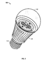
- FIG. 2 is a perspective view of an LED lamp in accordance with one embodiment presented herein.
- FIG. 3 is an exploded view of the LED lamp of FIG. 2 .
- FIG. 4 is an exploded view of a portion of the LED lamp of FIG. 2 .
- FIG. 5 is an exploded view of a portion of the LED lamp of FIG. 2 .
- FIG. 6 is an exploded view of a portion of the LED lamp of FIG. 2 .
- FIG. 7 is an exploded view of a portion of the LED lamp of FIG. 2 .
- FIG. 8 illustrates an optimal transmission curve for a color filter in accordance with one embodiment presented herein.
- FIG. 9 illustrates the light spectra of conventional light sources in comparison to the predicted melatonin suppression action spectrum for polychromatic light, as illustrated in FIG. 1 , and further including the light spectrum of an LED lamp in accordance with one embodiment presented herein.
- FIG. 2 is a perspective view of an LED lamp (or bulb) 100 in accordance with one embodiment presented herein.
- LED lamp 100 includes a base 110 , a heat sink 120 , and an optic 130 .
- LED lamp 100 further includes one or more LED chips and dedicated circuitry within LED lamp 100 .
- LED lamp 100 has been designed to produce a biologically-corrected light.
- biologically-corrected light is intended to mean “a light that has been modified to minimize or limit biological effects on a user.”
- biological effects is intended to mean “any impact or change a light source has to a naturally occurring function or process.”
- Biological effects may include hormone secretion or suppression (e.g., melatonin suppression), changes to cellular function, stimulation or disruption of natural processes, cellular mutations or manipulations, etc.
- Base 110 is preferably an Edison-type screw-in shell.
- Base 110 is preferably formed of an electrically conductive material such as aluminum.
- base 110 may be formed of other electrically conductive materials such as silver, copper, gold, conductive alloys, etc.
- Internal electrical leads are attached to base 110 to serve as contacts for a standard light socket (not shown).
- heat sink 120 serves as means for dissipating heat away from one or more of the LED chips within LED lamp 100 .
- heat sink 120 includes fins to increase the surface area of the heat sink.
- heat sink 120 may be formed of any configuration, size, or shape, with the general intention of drawings heat away from the LED chips within LED lamp 100 .
- Heat sink 120 is preferably formed of a thermally conductive material such as aluminum, copper, steel, etc.
- Optic 130 is provided to surround the LED chips within LED lamp 100 .
- the terms “surround” or “surrounding” are intended to mean partially or fully encapsulating.
- optic 130 surrounds the LED chips by partially or fully covering one or more LED chips such that light produced by one or more LED chips is transmitted through optic 130 .
- optic 130 takes a globular shape.
- Optic 130 may be formed of alternative forms, shapes, or sizes.
- optic 130 serves as an optic diffusing element by incorporating diffusing technology, such as described in U.S. Pat. No. 7,319,293 (which is incorporated herein by reference in its entirety).
- optic 130 serves as a means for defusing light from the LED chips.
- optic 130 may be formed of a light diffusive plastic, may include a light diffusive coating, or may having diffusive particles attached or embedded therein.
- optic 130 includes a color filter applied thereto.
- the color filter may be on the interior or exterior surface of optic 130 .
- the color filter is used to modify the light output from one or more of the LED chips.
- the color filter modifies the light so as to increase spectral opponency, and thereby minimize the biological effects of the light, while maintaining commercially acceptable color rendering characteristics.
- a color filter in accordance with the present invention is designed to do more than simply filter out the blue component light from the LED chips. Instead the color filter is configured to take advantage of spectral opponency; namely the phenomenon wherein wavelengths from one portion of the spectrum excite a response, while wavelengths from another portion inhibit a response.
- an LED lamp can be designed to maintain commercially acceptable color rendering properties, while minimizing the biological effects of the LED lamp.
- the LED lamp can provide relief for people who suffer from sleep disorders, circadian rhythm disruptions, and other biological system disruptions.
- FIG. 3 is an exploded view of LED lamp 100 , illustrating internal components of the lamp. As shown, in addition to the components described above, LED lamp 100 also includes at least a housing 115 , a printed circuit board (PCB) 117 , one or more LED chips 200 , a holder 125 , spring wire connectors 127 , and screws 129 .
- PCB printed circuit board
- PCB 117 includes dedicated circuitry to power, drive, and control one or more LED chips 200 .
- PCB 117 includes at least a driver circuit and a power circuit.
- the circuitry on PCB 117 serves as a means for driving the LED chips 200 .
- the driver circuit is configured to drive LED chips 200 with a ripple current at frequencies greater than 200 Hz.
- a ripple current at frequencies above 200 Hz is chosen to avoid biological effects that may be caused by ripple currents at frequencies below 200 Hz. For example, studies have shown that some individuals are sensitive to light flicker below 200 Hz, and in some instances experience aggravated headaches, seizures, etc.
- LED chips is meant to broadly encompass LED dies, with or without packaging and reflectors, that may or may not be treated (e.g., with applied phosphors). In the embodiment shown, however, LED chips 200 are “white LED chips” having a plurality of blue-pumped (about 465 nm) LED dies with a phosphor applied thereto. In alternative embodiments, LED chips 200 employ a garnet based phosphor, such as a Yttrium aluminum garnet (YAG) or dual-YAG phosphors, orthosilicate based phosphors, or quantum dots to create white light. In one embodiment, LED chips 200 emit light having a color temperature between about 2500 K and about 2900 K, and more preferably about 2700 K.
- YAG Yttrium aluminum garnet
- dual-YAG phosphors orthosilicate based phosphors
- quantum dots to create white light.
- LED chips 200 emit light having a color temperature between about 2500 K and about 2900 K, and more preferably about
- FIGS. 4-7 are exploded views of portions of LED lamp 100 .
- FIGS. 4-7 illustrate how to assemble LED lamp 100 .
- base 110 is glued or crimped onto housing 115 .
- PCB 117 is mounted within housing 115 .
- Insulation and/or potting compound may be used to secure PCB 117 within housing 115 .
- Electrical leads (not shown) on PCB 117 are coupled to base 110 to form the electrical input leads of LED lamp 100 .
- heat sink 120 is disposed about housing 115 .
- two LED chips 200 are mounted onto heat sink 120 , and maintained in place by holder 125 . While two LED chips 200 are shown, alternative embodiments may include any number of LED chips (i.e., one or more).
- Screws 129 are used to secure holder 125 to heat sink 120 . Screws 129 may be any screws known in the art (e.g., M2 plastite screws).
- Spring wire connectors 127 are used to connect LED chips 200 to the driver circuit on PCB 117 .
- LED chips 200 (with or without packaging) may be attached directly to heat sink 120 without the use of holder 125 , screws 129 , or connectors 127 .
- optic 130 is then mounted on and attached to heat sink 120 .
- FIG. 8 illustrates an optimal transmission curve for a color filter in accordance with one embodiment of the present invention.
- the inventors have found that the transmission curve of FIG. 8 provides increased spectral opponency, which minimizes biological effects, while maintaining a commercially acceptable color rendering index.
- application of a color filter having the transmission curve of FIG. 8 to LED lamp 100 results in a lamp having a color rendering index above 70, and more preferably above 80, and a color temperature between about 2,700 K and about 3,500 K, and more preferably about 3,015 K.
- LED lamp 100 produces no UV light.
- LED lamp 100 produces 400-800 lumens.
- the color filter is a ROSCOLUX #87 Pale Yellow Green color filter.
- the color filter has a total transmission of about 85%, a thickness of about 38 microns, and is formed of a deep-dyed polyester film.
- the color filter has transmission percentages within +/ ⁇ 10%, at one or more wavelengths, in accordance with the following table:
- Wavelength Transmission (%) 360 59 380 63 400 60 420 50 440 45 460 53 480 75 500 78 520 79 540 78 560 77 580 74 600 71 620 67 640 63 660 61 680 60 700 64 720 74 740 81
- color filters with equivalent transmission characteristics may be formed of absorptive or reflective coatings, thin-films, body-colored polycarbonate films, deep-dyed polyester films, surface-coated films, etc.
- pigment may be infused directly into the optic in order to produce the transmission filter effects.
- phosphors and/or quantum dots may be employed as “means for increasing the spectral opponency of the light output to limit the biological effect of the light output.”
- a combination of green converted and red converted phosphors can applied to the blue LED pump to create the light spectrum depicted in Curve E of FIG. 9 (discussed below).
- the term “a circadian-to-photopic ratio” is defined as “the ratio of melatonin suppressive light to total light output.” More specifically, the circadian-to-photopic ratio may be calculated as a unit-less ratio defined as:
- K 1 is set to equal K 2 .
- P ⁇ is the spectral power distribution of the light source.
- C( ⁇ ) is the circadian function (presented in the above referenced Figueiro et al. and Rea et al. publications).
- V( ⁇ ) is the photopic luminous efficiency function (presented in the above referenced Figueiro et al. and Rea et al. publications).
- the LED lamp produced in accordance with the present invention has a circadian-to-photopic ratio below about 0.10, and more preferably a circadian-to-photopic ratio below about 0.05, and most preferably a zero circadian-to-photopic ratio (i.e., no melatonin suppressive light is produced, although the lamp is generating a measurable amount of total light output).
- a circadian-to-photopic ratio of a 2856 K incandescent source to be about 0.138; of a white LED to be about 0.386; and of a fluorescent light source to be about 0.556.
- FIG. 9 illustrates the light spectra of conventional light sources in comparison to the predicted melatonin suppression action spectrum, as illustrated in FIG. 1 , and further including the light spectrum of an LED lamp in accordance with one embodiment of the present invention (Curve E).
- a color filter in accordance with the present invention does not necessarily filter out the entire blue component light of the LED chips.
- Curve E shows a blue component spike at about 450 nm.
- the color filter minimizes the biological effects of the light by compensating with spectral opponency.
- the color filter is designed to increase the yellow component light, which is the spectral opponent of blue light. As such, the resulting light source can maintain commercially acceptable color rendering properties, while minimizing biological effects.
- a biologically-corrected LED lamp comprising: a housing; a driver circuit disposed within the housing; a plurality of LED chips electrically coupled to and driven by the driver circuit, wherein the plurality of LED chips produce a light output; and an optic element surrounding the plurality of LED chips.
- the optic element has a color filter applied thereto. The color filter is configured to increase spectral opponency to thereby decrease a biological effect of melatonin suppression of the light output of the plurality of LED chips.
- the lamp further comprises a heat sink disposed about the housing.
- the driver circuit of the lamp is configured to drive the plurality of LED chips with a ripple current at frequencies greater than 200 Hz.
- the plurality of LED chips are blue-pumped white LED chips.
- light output of the plurality of LED chips has a color temperature between about 2,500 K and about 2,900 K. In another embodiment, the light output of the plurality of LED chips has a color temperature of about 2,700 K.
- the lamp has a color rendering index above 70, and a color temperature between about 2,700 K and about 3,500 K.
- a biologically-corrected LED lamp comprising a housing; a driver circuit disposed within the housing; a plurality of LED chips electrically coupled to and driven by the driver circuit, wherein the plurality of LED chips produce a light output; and an optic element surrounding the plurality of LED chips.
- the optic element has a color filter applied thereto.
- the color filter is configured to increase spectral opponency to thereby decrease a melatonin suppressive effect of the light output of the plurality of LED chips.
- the color filter has a total transmission of about 85%, a thickness of about 38 microns, and is formed of a deep-dyed polyester film.
- the lamp further comprises a heat sink disposed about the housing.
- the plurality of LED chips are blue-pumped white LED chips.
- light output of the plurality of LED chips has a color temperature between about 2,500 K and about 2,900 K. In another embodiment, the light output of the plurality of LED chips has a color temperature of about 2,700 K.
- the lamp has a color rendering index above 70, and a color temperature between about 2,700 K and about 3,500 K.
- a biologically-corrected LED lamp comprising: a housing; a driver circuit disposed within the housing; a plurality of LED chips electrically coupled to and driven by the driver circuit, wherein the plurality of LED chips produce a light output; and an optic element surrounding the plurality of LED chips.
- the optic element has a color filter applied thereto.
- the color filter is configured to increase spectral opponency to thereby decrease a melatonin suppressive effect of the light output of the plurality of LED chips.
- the color filter has a polyethylene terephthalate substrate.
- the lamp further comprises a heat sink disposed about the housing.
- the driver circuit of the lamp is configured to drive the plurality of LED chips with a ripple current at frequencies greater than 200 Hz.
- the plurality of LED chips are blue-pumped white LED chips.
- light output of the plurality of LED chips has a color temperature between about 2,500 K and about 2,900 K. In another embodiment, the light output of the plurality of LED chips has a color temperature of about 2,700 K.
- the lamp has a color rendering index above 70, and a color temperature between about 2,700 K and about 3,500 K.
- a biologically-corrected LED lamp comprising a housing; a driver circuit disposed within the housing; a plurality of LED chips electrically coupled to and driven by the driver circuit, wherein the plurality of LED chips produce a light output; and an optic element surrounding the plurality of LED chips.
- the optic element has a color filter applied thereto.
- the color filter is configured to increase spectral opponency to thereby decrease a melatonin suppressive effect of the light output of the plurality of LED chips.
- the color filter is a ROSCOLUX #87 Pale Yellow Green color filter.
- the lamp further comprises a heat sink disposed about the housing.
- the driver circuit of the lamp is configured to drive the plurality of LED chips with a ripple current at frequencies greater than 200 Hz.
- the plurality of LED chips are blue-pumped white LED chips.
- light output of the plurality of LED chips has a color temperature between about 2,500 K and about 2,900 K. In another embodiment, the light output of the plurality of LED chips has a color temperature of about 2,700 K.
- the lamp has a color rendering index above 70, and a color temperature between about 2,700 K and about 3,500 K.
- a biologically-corrected LED lamp comprising: a housing; a driver circuit disposed within the housing; a plurality of LED chips electrically coupled to and driven by the driver circuit, wherein the plurality of LED chips produce a light output; and an optic element surrounding the plurality of LED chips.
- the optic element has a color filter applied thereto. The color filter is configured to increase spectral opponency to thereby decrease a melatonin suppressive effect of the light output of the plurality of LED chips.
- the color filter has a transmission of about 45% at a wavelength of about 440 nm, a transmission of about 53% at a wavelength of about 460 nm, a transmission of about 75% at a wavelength of about 480 nm, a transmission of about 77% at a wavelength of about 560 nm, a transmission of about 74% at a wavelength of about 580 nm, and a transmission of about 71% at a wavelength of about 600 nm.
- the lamp further comprises a heat sink disposed about the housing.
- the driver circuit of the lamp is configured to drive the plurality of LED chips with a ripple current at frequencies greater than 200 Hz.
- the plurality of LED chips are blue-pumped white LED chips.
- light output of the plurality of LED chips has a color temperature between about 2,500 K and about 2,900 K. In another embodiment, the light output of the plurality of LED chips has a color temperature of about 2,700 K.
- the lamp has a color rendering index above 70, and a color temperature between about 2,700 K and about 3,500 K.
- a lamp comprising: a housing; a driver circuit disposed within the housing; at least one LED chip electrically coupled to and driven by the driver circuit to produce a light output; and means for increasing the spectral opponency of the light output to limit the biological effect of the light output.
- the biological effect may be melatonin suppression, circadian rhythm disruption, or any other biological system disruption.
- the driver of the lamp is configured to drive the LED chip with a ripple current greater at frequencies than 200 Hz.
- the means for increasing the spectral opponency of the light output to limit the biological effect of the light output is configured such that the lamp produces a resulting light output having a color temperature between about 2,700 K and about 3,500 K. In an embodiment, the means for increasing the spectral opponency of the light output to limit the biological effect of the light output is configured such that the lamp produces a resulting light output having a color rendering index above 70. In an embodiment, the means for increasing the spectral opponency of the light output to limit the biological effect of the light output is configured such that the lamp produces a circadian-to-photopic ratio below about 0.05.
- the lamp further includes a heat sink disposed about the housing.
- a biologically-corrected LED lamp having a color rendering index above 70 and a color temperature between about 2,700 K and about 3,500 K, wherein the lamp produces a spectral power distribution that increases spectral opponency to thereby minimize melatonin suppression.
- the lamp comprises: a base; a housing attached to the base; a power circuit disposed within the housing and having electrical leads attached to the base; a driver circuit disposed within the housing and electrically coupled to the power circuit; a heat sink disposed about the housing; a plurality of LED chips electrically coupled to and driven by the driver circuit, wherein the plurality of LED chips are coupled to the heat sink, wherein the plurality of LED chips are blue-pumped white LED chips that produce light having a color temperature of about 2,700 K, and wherein the driver circuit is configured to drive the plurality of LED chips with a ripple current at frequencies greater than 200 Hz; and optic diffusing element mounted on the heat sink and surrounding the plurality of LED chips, wherein the optic diffusing element has a color filter applied thereto, and wherein the color filter is configured to increase spectral opponency to thereby decrease a melatonin suppressive effect of a light output from the plurality of LED chips.
- the color filter has a total transmission of about 85%, a thickness of about 38 micro
- a biologically-corrected LED lamp having a color rendering index above 70 and a color temperature between about 2,700 K and about 3,500 K, wherein the lamp produces a spectral power distribution that increases spectral opponency to thereby minimize melatonin suppression.
- the lamp comprises: a base; a housing attached to the base; a power circuit disposed within the housing and having electrical leads attached to the base; a driver circuit disposed within the housing and electrically coupled to the power circuit; a heat sink disposed about the housing; a plurality of LED chips electrically coupled to and driven by the driver circuit, wherein the plurality of LED chips are coupled to the heat sink, wherein the plurality of LED chips are blue-pumped white LED chips that produce light having a color temperature of about 2,700 K, and wherein the driver circuit is configured to drive the plurality of LED chips with a ripple current at frequencies greater than 200 Hz; and optic diffusing element mounted on the heat sink and surrounding the plurality of LED chips, wherein the optic diffusing element has a color filter applied thereto, and wherein the color filter is configured to increase spectral opponency to thereby decrease a melatonin suppressive effect of a light output from the plurality of LED chips.
- the color filter has a polyethylene terephthalate substrate.
- a biologically-corrected LED lamp having a color rendering index above 70 and a color temperature between about 2,700 K and about 3,500 K, wherein the lamp produces a spectral power distribution that increases spectral opponency to thereby minimize melatonin suppression.
- the lamp comprises: a base; a housing attached to the base; a power circuit disposed within the housing and having electrical leads attached to the base; a driver circuit disposed within the housing and electrically coupled to the power circuit; a heat sink disposed about the housing; a plurality of LED chips electrically coupled to and driven by the driver circuit, wherein the plurality of LED chips are coupled to the heat sink, wherein the plurality of LED chips are blue-pumped white LED chips that produce light having a color temperature of about 2,700 K, and wherein the driver circuit is configured to drive the plurality of LED chips with a ripple current at frequencies greater than 200 Hz; and optic diffusing element mounted on the heat sink and surrounding the plurality of LED chips, wherein the optic diffusing element has a color filter applied thereto, and wherein the color filter is configured to increase spectral opponency to thereby decrease a melatonin suppressive effect of a light output from the plurality of LED chips.
- the color filter is a ROSCOLUX #87 Pale Yellow Green color filter.
- a biologically-corrected LED lamp having a color rendering index above 70 and a color temperature between about 2,700 K and about 3,500 K, wherein the lamp produces a spectral power distribution that increases spectral opponency to thereby minimize melatonin suppression.
- the lamp comprises: a base; a housing attached to the base; a power circuit disposed within the housing and having electrical leads attached to the base; a driver circuit disposed within the housing and electrically coupled to the power circuit; a heat sink disposed about the housing; a plurality of LED chips electrically coupled to and driven by the driver circuit, wherein the plurality of LED chips are coupled to the heat sink, wherein the plurality of LED chips are blue-pumped white LED chips that produce light having a color temperature of about 2,700 K, and wherein the driver circuit is configured to drive the plurality of LED chips with a ripple current at frequencies greater than 200 Hz; and optic diffusing element mounted on the heat sink and surrounding the plurality of LED chips, wherein the optic diffusing element has a color filter applied thereto, and wherein the color filter is configured to increase spectral opponency to thereby decrease a melatonin suppressive effect of a light output from the plurality of LED chips.
- the color filter has a transmission of about 45% at a wavelength of about 440 nm, a transmission of about 53% at a wavelength of about 460 nm, a transmission of about 75% at a wavelength of about 480 nm, a transmission of about 77% at a wavelength of about 560 nm, a transmission of about 74% at a wavelength of about 580 nm, and a transmission of about 71% at a wavelength of about 600 nm.
- a method of minimizing a biological effect produced by a white LED lamp wherein the LED lamp includes a housing, a driver circuit disposed within the housing, a plurality of LED chips electrically coupled to and driven by the driver circuit, wherein the plurality of LED chips produce a light output, and an optic element surrounding the plurality of LED chips.
- the method comprises applying to the optic element a color filter configured to increase spectral opponency.
- the method may also comprise configuring the driver circuit to drive the LED chip with a ripple current at frequencies greater than 200 Hz.
- a white LED lamp in another example, there is provided a method of minimizing a biological effect produced by a white LED lamp, wherein the LED lamp includes a housing, a driver circuit disposed within the housing, a plurality of LED chips electrically coupled to and driven by the driver circuit, wherein the plurality of LED chips produce a light output, and an optic element surrounding the plurality of LED chips.
- the method comprises applying to the optic element a color filter having a transmission of about 45% at a wavelength of about 440 nm, about 53% at a wavelength of about 460 nm, about 75% at a wavelength of about 480 nm, about 77% at a wavelength of about 560 nm, about 74% at a wavelength of about 580 nm, and about 71% at a wavelength of about 600 nm.
- the method may also comprise configuring the driver circuit to drive the LED chip with a ripple current at frequencies greater than 200 Hz.
- a method of increasing spectral opponency of an LED lamp comprising: applying to the LED lamp a ROSCOLUX #87 Pale Yellow Green color filter.
Abstract
Description
-
- Figueiro, et al., “Spectral Sensitivity of the Circadian System,” Lighting Research Center, available at: http://www.lrc.rpi.edu/programs/lightHealth/pdf/spectralSensitivity.pdf.
- Rea, et al., “Circadian Light,” Journal of Circadian Rhythms, 8:20 (2010).
- Stevens, R. G., “Electric power use and breast cancer; a hypothesis,” American Journal of Epidemiology, 125:4, pgs. 556-561 (1987).
- Veitch, et al., “Modulation of Fluorescent Light: Flicker Rate and Light Source Effects on Visual Performance and Visual Comfort.
| Wavelength | Transmission (%) | ||
| 360 | 59 | ||
| 380 | 63 | ||
| 400 | 60 | ||
| 420 | 50 | ||
| 440 | 45 | ||
| 460 | 53 | ||
| 480 | 75 | ||
| 500 | 78 | ||
| 520 | 79 | ||
| 540 | 78 | ||
| 560 | 77 | ||
| 580 | 74 | ||
| 600 | 71 | ||
| 620 | 67 | ||
| 640 | 63 | ||
| 660 | 61 | ||
| 680 | 60 | ||
| 700 | 64 | ||
| 720 | 74 | ||
| 740 | 81 | ||
Claims (13)
Priority Applications (19)
| Application Number | Priority Date | Filing Date | Title |
|---|---|---|---|
| US12/842,887 US8253336B2 (en) | 2010-07-23 | 2010-07-23 | LED lamp for producing biologically-corrected light |
| US13/174,339 US8324808B2 (en) | 2010-07-23 | 2011-06-30 | LED lamp for producing biologically-corrected light |
| EP11810175.7A EP2596283B1 (en) | 2010-07-23 | 2011-07-13 | Led lamp for producing biologically-corrected light |
| JP2013520746A JP5907962B2 (en) | 2010-07-23 | 2011-07-13 | LED lamp for generating biological correction light |
| CN201180036133.9A CN103026131B (en) | 2010-07-23 | 2011-07-13 | LED lamp for producing biologically-corrected light |
| PCT/US2011/043884 WO2012012245A2 (en) | 2010-07-23 | 2011-07-13 | Led lamp for producing biologically-corrected light |
| TW100125951A TW201231880A (en) | 2010-07-23 | 2011-07-22 | LED lamp for producing biologically-corrected light |
| US13/559,180 US8446095B2 (en) | 2010-07-23 | 2012-07-26 | LED lamp for producing biologically-corrected light |
| US13/652,207 US8643276B2 (en) | 2010-07-23 | 2012-10-15 | LED lamp for producing biologically-corrected light |
| IL224378A IL224378A (en) | 2010-07-23 | 2013-01-23 | Led lamp for producing biologically-corrected light |
| US13/803,825 US8743023B2 (en) | 2010-07-23 | 2013-03-14 | System for generating non-homogenous biologically-adjusted light and associated methods |
| HK13110166.2A HK1182757A1 (en) | 2010-07-23 | 2013-08-30 | Led lamp for producing biologically-corrected light led |
| US14/260,371 US9265968B2 (en) | 2010-07-23 | 2014-04-24 | System for generating non-homogenous biologically-adjusted light and associated methods |
| US14/573,922 US9532423B2 (en) | 2010-07-23 | 2014-12-17 | System and methods for operating a lighting device |
| US14/590,557 US9827439B2 (en) | 2010-07-23 | 2015-01-06 | System for dynamically adjusting circadian rhythm responsive to scheduled events and associated methods |
| US15/370,802 US9794996B2 (en) | 2010-07-23 | 2016-12-06 | System and methods for operating a lighting device |
| US15/483,327 US9974973B2 (en) | 2010-07-23 | 2017-04-10 | System and associated methods for dynamically adjusting circadian rhythm responsive to calendared future events |
| US15/935,391 US10258808B2 (en) | 2010-07-23 | 2018-03-26 | System and associated methods for dynamically adjusting circadian rhythm responsive to identified future events |
| US16/271,208 US10765886B2 (en) | 2010-07-23 | 2019-02-08 | System, user device and associated methods for dynamically adjusting circadian rhythm responsive to future events |
Applications Claiming Priority (1)
| Application Number | Priority Date | Filing Date | Title |
|---|---|---|---|
| US12/842,887 US8253336B2 (en) | 2010-07-23 | 2010-07-23 | LED lamp for producing biologically-corrected light |
Related Parent Applications (1)
| Application Number | Title | Priority Date | Filing Date |
|---|---|---|---|
| US13/775,936 Continuation-In-Part US9681522B2 (en) | 2010-07-23 | 2013-02-25 | Adaptive light system and associated methods |
Related Child Applications (2)
| Application Number | Title | Priority Date | Filing Date |
|---|---|---|---|
| US13/174,339 Continuation-In-Part US8324808B2 (en) | 2010-07-23 | 2011-06-30 | LED lamp for producing biologically-corrected light |
| US13/559,180 Continuation US8446095B2 (en) | 2010-07-23 | 2012-07-26 | LED lamp for producing biologically-corrected light |
Publications (2)
| Publication Number | Publication Date |
|---|---|
| US20120019138A1 US20120019138A1 (en) | 2012-01-26 |
| US8253336B2 true US8253336B2 (en) | 2012-08-28 |
Family
ID=45493051
Family Applications (2)
| Application Number | Title | Priority Date | Filing Date |
|---|---|---|---|
| US12/842,887 Active 2031-01-11 US8253336B2 (en) | 2010-07-23 | 2010-07-23 | LED lamp for producing biologically-corrected light |
| US13/559,180 Active US8446095B2 (en) | 2010-07-23 | 2012-07-26 | LED lamp for producing biologically-corrected light |
Family Applications After (1)
| Application Number | Title | Priority Date | Filing Date |
|---|---|---|---|
| US13/559,180 Active US8446095B2 (en) | 2010-07-23 | 2012-07-26 | LED lamp for producing biologically-corrected light |
Country Status (1)
| Country | Link |
|---|---|
| US (2) | US8253336B2 (en) |
Cited By (29)
| Publication number | Priority date | Publication date | Assignee | Title |
|---|---|---|---|---|
| US8643276B2 (en) * | 2010-07-23 | 2014-02-04 | Biological Illumination, Llc | LED lamp for producing biologically-corrected light |
| US8680457B2 (en) | 2012-05-07 | 2014-03-25 | Lighting Science Group Corporation | Motion detection system and associated methods having at least one LED of second set of LEDs to vary its voltage |
| US8686641B2 (en) | 2011-12-05 | 2014-04-01 | Biological Illumination, Llc | Tunable LED lamp for producing biologically-adjusted light |
| US8743023B2 (en) | 2010-07-23 | 2014-06-03 | Biological Illumination, Llc | System for generating non-homogenous biologically-adjusted light and associated methods |
| US8754832B2 (en) | 2011-05-15 | 2014-06-17 | Lighting Science Group Corporation | Lighting system for accenting regions of a layer and associated methods |
| US8760370B2 (en) | 2011-05-15 | 2014-06-24 | Lighting Science Group Corporation | System for generating non-homogenous light and associated methods |
| US8761447B2 (en) * | 2010-11-09 | 2014-06-24 | Biological Illumination, Llc | Sustainable outdoor lighting system for use in environmentally photo-sensitive area |
| US8841864B2 (en) | 2011-12-05 | 2014-09-23 | Biological Illumination, Llc | Tunable LED lamp for producing biologically-adjusted light |
| US8866414B2 (en) | 2011-12-05 | 2014-10-21 | Biological Illumination, Llc | Tunable LED lamp for producing biologically-adjusted light |
| US8901850B2 (en) | 2012-05-06 | 2014-12-02 | Lighting Science Group Corporation | Adaptive anti-glare light system and associated methods |
| US8963450B2 (en) | 2011-12-05 | 2015-02-24 | Biological Illumination, Llc | Adaptable biologically-adjusted indirect lighting device and associated methods |
| USD723729S1 (en) | 2013-03-15 | 2015-03-03 | Lighting Science Group Corporation | Low bay luminaire |
| US9006987B2 (en) | 2012-05-07 | 2015-04-14 | Lighting Science Group, Inc. | Wall-mountable luminaire and associated systems and methods |
| US9024536B2 (en) | 2011-12-05 | 2015-05-05 | Biological Illumination, Llc | Tunable LED lamp for producing biologically-adjusted light and associated methods |
| US9173269B2 (en) | 2011-05-15 | 2015-10-27 | Lighting Science Group Corporation | Lighting system for accentuating regions of a layer and associated methods |
| US9174067B2 (en) | 2012-10-15 | 2015-11-03 | Biological Illumination, Llc | System for treating light treatable conditions and associated methods |
| US9220202B2 (en) | 2011-12-05 | 2015-12-29 | Biological Illumination, Llc | Lighting system to control the circadian rhythm of agricultural products and associated methods |
| US9289574B2 (en) | 2011-12-05 | 2016-03-22 | Biological Illumination, Llc | Three-channel tuned LED lamp for producing biologically-adjusted light |
| US9347655B2 (en) | 2013-03-11 | 2016-05-24 | Lighting Science Group Corporation | Rotatable lighting device |
| US9402294B2 (en) | 2012-05-08 | 2016-07-26 | Lighting Science Group Corporation | Self-calibrating multi-directional security luminaire and associated methods |
| US9532423B2 (en) | 2010-07-23 | 2016-12-27 | Lighting Science Group Corporation | System and methods for operating a lighting device |
| US9612002B2 (en) | 2012-10-18 | 2017-04-04 | GE Lighting Solutions, LLC | LED lamp with Nd-glass bulb |
| US9681522B2 (en) | 2012-05-06 | 2017-06-13 | Lighting Science Group Corporation | Adaptive light system and associated methods |
| US9693414B2 (en) | 2011-12-05 | 2017-06-27 | Biological Illumination, Llc | LED lamp for producing biologically-adjusted light |
| US9788387B2 (en) | 2015-09-15 | 2017-10-10 | Biological Innovation & Optimization Systems, LLC | Systems and methods for controlling the spectral content of LED lighting devices |
| US9827439B2 (en) | 2010-07-23 | 2017-11-28 | Biological Illumination, Llc | System for dynamically adjusting circadian rhythm responsive to scheduled events and associated methods |
| US9844116B2 (en) | 2015-09-15 | 2017-12-12 | Biological Innovation & Optimization Systems, LLC | Systems and methods for controlling the spectral content of LED lighting devices |
| US9943042B2 (en) | 2015-05-18 | 2018-04-17 | Biological Innovation & Optimization Systems, LLC | Grow light embodying power delivery and data communications features |
| US10595376B2 (en) | 2016-09-13 | 2020-03-17 | Biological Innovation & Optimization Systems, LLC | Systems and methods for controlling the spectral content of LED lighting devices |
Families Citing this family (14)
| Publication number | Priority date | Publication date | Assignee | Title |
|---|---|---|---|---|
| CN201944569U (en) * | 2010-10-29 | 2011-08-24 | 东莞巨扬电器有限公司 | A microwave sensing LED bulb |
| KR102407182B1 (en) * | 2011-05-31 | 2022-06-10 | 클라렌슈 피티와이 리미티드 | Light therapy apparatuses |
| USD696436S1 (en) | 2011-06-23 | 2013-12-24 | Cree, Inc. | Solid state directional lamp |
| US8777463B2 (en) * | 2011-06-23 | 2014-07-15 | Cree, Inc. | Hybrid solid state emitter printed circuit board for use in a solid state directional lamp |
| KR101349513B1 (en) * | 2012-03-20 | 2014-01-09 | 엘지이노텍 주식회사 | Lighting apparatus and lighting system |
| EP2901184A4 (en) * | 2012-09-26 | 2015-11-18 | 8797625 Canada Inc | Multilayer optical interference filter |
| CN105210452A (en) * | 2013-03-14 | 2015-12-30 | 生物照明有限责任公司 | System for generating non-homogenous biologically-adjusted light and associated methods |
| US10642087B2 (en) | 2014-05-23 | 2020-05-05 | Eyesafe, Llc | Light emission reducing compounds for electronic devices |
| US9410676B1 (en) * | 2015-03-20 | 2016-08-09 | Green Creative, Llc | LED light bulb |
| KR102253975B1 (en) * | 2016-09-12 | 2021-05-18 | 루미레즈 엘엘씨 | Lighting system with reduced melanopic spectral component |
| CN108712805A (en) * | 2018-07-24 | 2018-10-26 | 谢记平 | A kind of adaptive LED driving current ripple control circuit |
| US11810532B2 (en) | 2018-11-28 | 2023-11-07 | Eyesafe Inc. | Systems for monitoring and regulating harmful blue light exposure from digital devices |
| US11490479B2 (en) | 2020-01-09 | 2022-11-01 | Leddynamics, Inc. | Systems and methods for tunable LED lighting |
| WO2023097036A1 (en) * | 2021-11-26 | 2023-06-01 | Eyesafe Inc. | Light emission reducing compounds and phosphor coatings for electronic devices |
Citations (34)
| Publication number | Priority date | Publication date | Assignee | Title |
|---|---|---|---|---|
| US6259572B1 (en) | 1996-02-21 | 2001-07-10 | Rosco Laboratories, Inc. | Photographic color effects lighting filter system |
| US6586882B1 (en) | 1999-04-20 | 2003-07-01 | Koninklijke Philips Electronics N.V. | Lighting system |
| US6734639B2 (en) * | 2001-08-15 | 2004-05-11 | Koninklijke Philips Electronics N.V. | Sample and hold method to achieve square-wave PWM current source for light emitting diode arrays |
| US20040093045A1 (en) * | 2002-10-23 | 2004-05-13 | Charles Bolta | Balanced blue spectrum therapy lighting |
| US20040119086A1 (en) | 2002-11-25 | 2004-06-24 | Matsushita Electric Industrial Co. Ltd. | Led Lamp |
| US6762562B2 (en) * | 2002-11-19 | 2004-07-13 | Denovo Lighting, Llc | Tubular housing with light emitting diodes |
| US20050189557A1 (en) | 2004-02-26 | 2005-09-01 | Joseph Mazzochette | Light emitting diode package assembly that emulates the light pattern produced by an incandescent filament bulb |
| US20050267213A1 (en) | 2004-01-08 | 2005-12-01 | Dusa Pharmaceuticals, Inc. | Use of photodynamic therapy to enhance treatment with immuno-modulating agents |
| US7095053B2 (en) | 2003-05-05 | 2006-08-22 | Lamina Ceramics, Inc. | Light emitting diodes packaged for high temperature operation |
| US7144131B2 (en) * | 2004-09-29 | 2006-12-05 | Advanced Optical Technologies, Llc | Optical system using LED coupled with phosphor-doped reflective materials |
| US7157745B2 (en) | 2004-04-09 | 2007-01-02 | Blonder Greg E | Illumination devices comprising white light emitting diodes and diode arrays and method and apparatus for making them |
| US7234844B2 (en) | 2002-12-11 | 2007-06-26 | Charles Bolta | Light emitting diode (L.E.D.) lighting fixtures with emergency back-up and scotopic enhancement |
| US7252408B2 (en) | 2004-07-19 | 2007-08-07 | Lamina Ceramics, Inc. | LED array package with internal feedback and control |
| US20070262714A1 (en) | 2006-05-15 | 2007-11-15 | X-Rite, Incorporated | Illumination source including photoluminescent material and a filter, and an apparatus including same |
| US7319293B2 (en) | 2004-04-30 | 2008-01-15 | Lighting Science Group Corporation | Light bulb having wide angle light dispersion using crystalline material |
| US20080119912A1 (en) * | 2006-01-11 | 2008-05-22 | Stephen Bryce Hayes | Phototherapy lights |
| US20080231214A1 (en) | 2007-03-19 | 2008-09-25 | Seoul Semiconductor Co., Ltd. | Light emitting device having various color temperature |
| US20080266690A1 (en) * | 2005-03-16 | 2008-10-30 | Matsushita Electric Works, Ltd. | Optical Filter and Lighting Apparatus |
| US7497596B2 (en) | 2001-12-29 | 2009-03-03 | Mane Lou | LED and LED lamp |
| US7520607B2 (en) | 2002-08-28 | 2009-04-21 | Melcort Inc. | Device for the prevention of melationin suppression by light at night |
| US7521875B2 (en) | 2004-04-23 | 2009-04-21 | Lighting Science Group Corporation | Electronic light generating element light bulb |
| US7528421B2 (en) | 2003-05-05 | 2009-05-05 | Lamina Lighting, Inc. | Surface mountable light emitting diode assemblies packaged for high temperature operation |
| US7556376B2 (en) | 2006-08-23 | 2009-07-07 | High Performance Optics, Inc. | System and method for selective light inhibition |
| US7619372B2 (en) | 2007-03-02 | 2009-11-17 | Lighting Science Group Corporation | Method and apparatus for driving a light emitting diode |
| US7633779B2 (en) | 2007-01-31 | 2009-12-15 | Lighting Science Group Corporation | Method and apparatus for operating a light emitting diode with a dimmer |
| US7633093B2 (en) | 2003-05-05 | 2009-12-15 | Lighting Science Group Corporation | Method of making optical light engines with elevated LEDs and resulting product |
| US7637643B2 (en) | 2007-11-27 | 2009-12-29 | Lighting Science Group Corporation | Thermal and optical control in a light fixture |
| US20100085758A1 (en) | 2008-10-02 | 2010-04-08 | Hidenori Takahashi | Light source device |
| US7708452B2 (en) | 2006-06-08 | 2010-05-04 | Lighting Science Group Corporation | Lighting apparatus including flexible power supply |
| US20100118510A1 (en) | 2007-02-15 | 2010-05-13 | Lighting Science Group Corporation | High color rendering index white led light system using multi-wavelength pump sources and mixed phosphors |
| US20100157573A1 (en) | 2008-12-19 | 2010-06-24 | Panasonic Electric Works Co., Ltd. | Light source apparatus |
| US20100171441A1 (en) * | 2007-05-25 | 2010-07-08 | Koninklijke Philips Electronics N.V. | Lighting system for creating a biological effect |
| US20100244740A1 (en) * | 2007-08-24 | 2010-09-30 | Photonic Developments Llc | Multi-chip light emitting diode light device |
| US7976182B2 (en) * | 2007-03-21 | 2011-07-12 | International Rectifier Corporation | LED lamp assembly with temperature control and method of making the same |
Family Cites Families (3)
| Publication number | Priority date | Publication date | Assignee | Title |
|---|---|---|---|---|
| US6902296B2 (en) * | 2002-06-15 | 2005-06-07 | Searfoss, Iii Robert Lee | Nightlight for phototherapy |
| US20100244735A1 (en) * | 2009-03-26 | 2010-09-30 | Energy Focus, Inc. | Lighting Device Supplying Temporally Appropriate Light |
| TW201201876A (en) * | 2010-07-09 | 2012-01-16 | Nat Univ Tsing Hua | Lighting device capable of reducing the phenomenon of melatonin suppression |
-
2010
- 2010-07-23 US US12/842,887 patent/US8253336B2/en active Active
-
2012
- 2012-07-26 US US13/559,180 patent/US8446095B2/en active Active
Patent Citations (34)
| Publication number | Priority date | Publication date | Assignee | Title |
|---|---|---|---|---|
| US6259572B1 (en) | 1996-02-21 | 2001-07-10 | Rosco Laboratories, Inc. | Photographic color effects lighting filter system |
| US6586882B1 (en) | 1999-04-20 | 2003-07-01 | Koninklijke Philips Electronics N.V. | Lighting system |
| US6734639B2 (en) * | 2001-08-15 | 2004-05-11 | Koninklijke Philips Electronics N.V. | Sample and hold method to achieve square-wave PWM current source for light emitting diode arrays |
| US7497596B2 (en) | 2001-12-29 | 2009-03-03 | Mane Lou | LED and LED lamp |
| US7520607B2 (en) | 2002-08-28 | 2009-04-21 | Melcort Inc. | Device for the prevention of melationin suppression by light at night |
| US20040093045A1 (en) * | 2002-10-23 | 2004-05-13 | Charles Bolta | Balanced blue spectrum therapy lighting |
| US6762562B2 (en) * | 2002-11-19 | 2004-07-13 | Denovo Lighting, Llc | Tubular housing with light emitting diodes |
| US20040119086A1 (en) | 2002-11-25 | 2004-06-24 | Matsushita Electric Industrial Co. Ltd. | Led Lamp |
| US7234844B2 (en) | 2002-12-11 | 2007-06-26 | Charles Bolta | Light emitting diode (L.E.D.) lighting fixtures with emergency back-up and scotopic enhancement |
| US7095053B2 (en) | 2003-05-05 | 2006-08-22 | Lamina Ceramics, Inc. | Light emitting diodes packaged for high temperature operation |
| US7633093B2 (en) | 2003-05-05 | 2009-12-15 | Lighting Science Group Corporation | Method of making optical light engines with elevated LEDs and resulting product |
| US7528421B2 (en) | 2003-05-05 | 2009-05-05 | Lamina Lighting, Inc. | Surface mountable light emitting diode assemblies packaged for high temperature operation |
| US20050267213A1 (en) | 2004-01-08 | 2005-12-01 | Dusa Pharmaceuticals, Inc. | Use of photodynamic therapy to enhance treatment with immuno-modulating agents |
| US20050189557A1 (en) | 2004-02-26 | 2005-09-01 | Joseph Mazzochette | Light emitting diode package assembly that emulates the light pattern produced by an incandescent filament bulb |
| US7157745B2 (en) | 2004-04-09 | 2007-01-02 | Blonder Greg E | Illumination devices comprising white light emitting diodes and diode arrays and method and apparatus for making them |
| US7521875B2 (en) | 2004-04-23 | 2009-04-21 | Lighting Science Group Corporation | Electronic light generating element light bulb |
| US7319293B2 (en) | 2004-04-30 | 2008-01-15 | Lighting Science Group Corporation | Light bulb having wide angle light dispersion using crystalline material |
| US7252408B2 (en) | 2004-07-19 | 2007-08-07 | Lamina Ceramics, Inc. | LED array package with internal feedback and control |
| US7144131B2 (en) * | 2004-09-29 | 2006-12-05 | Advanced Optical Technologies, Llc | Optical system using LED coupled with phosphor-doped reflective materials |
| US20080266690A1 (en) * | 2005-03-16 | 2008-10-30 | Matsushita Electric Works, Ltd. | Optical Filter and Lighting Apparatus |
| US20080119912A1 (en) * | 2006-01-11 | 2008-05-22 | Stephen Bryce Hayes | Phototherapy lights |
| US20070262714A1 (en) | 2006-05-15 | 2007-11-15 | X-Rite, Incorporated | Illumination source including photoluminescent material and a filter, and an apparatus including same |
| US7708452B2 (en) | 2006-06-08 | 2010-05-04 | Lighting Science Group Corporation | Lighting apparatus including flexible power supply |
| US7556376B2 (en) | 2006-08-23 | 2009-07-07 | High Performance Optics, Inc. | System and method for selective light inhibition |
| US7633779B2 (en) | 2007-01-31 | 2009-12-15 | Lighting Science Group Corporation | Method and apparatus for operating a light emitting diode with a dimmer |
| US20100118510A1 (en) | 2007-02-15 | 2010-05-13 | Lighting Science Group Corporation | High color rendering index white led light system using multi-wavelength pump sources and mixed phosphors |
| US7619372B2 (en) | 2007-03-02 | 2009-11-17 | Lighting Science Group Corporation | Method and apparatus for driving a light emitting diode |
| US20080231214A1 (en) | 2007-03-19 | 2008-09-25 | Seoul Semiconductor Co., Ltd. | Light emitting device having various color temperature |
| US7976182B2 (en) * | 2007-03-21 | 2011-07-12 | International Rectifier Corporation | LED lamp assembly with temperature control and method of making the same |
| US20100171441A1 (en) * | 2007-05-25 | 2010-07-08 | Koninklijke Philips Electronics N.V. | Lighting system for creating a biological effect |
| US20100244740A1 (en) * | 2007-08-24 | 2010-09-30 | Photonic Developments Llc | Multi-chip light emitting diode light device |
| US7637643B2 (en) | 2007-11-27 | 2009-12-29 | Lighting Science Group Corporation | Thermal and optical control in a light fixture |
| US20100085758A1 (en) | 2008-10-02 | 2010-04-08 | Hidenori Takahashi | Light source device |
| US20100157573A1 (en) | 2008-12-19 | 2010-06-24 | Panasonic Electric Works Co., Ltd. | Light source apparatus |
Non-Patent Citations (20)
| Title |
|---|
| Binnie et al. (1979) "Fluorescent Lighting and Epilepsy" Epilepsia 20(6):725-727. |
| Charamisinau et al. (2005) "Semiconductor laser insert with Uniform Illumination for Use in Photodynamic Therapy" Appl Opt 44(24):5055-5068. |
| ERBA Shedding Light on Photosensitivity, One of Epilepsy's Most Complex Conditions. Photosensitivity and Epilepsy. Epilepsy Foundation. Accessed: Aug. 28, 2009. http://www.epilepsyfoundation.org/aboutepilepsy/seizures/photosensitivity/gerba.cfm. |
| Figueiro et al. (2004) "Spectral Sensitivity of the Circadian System" Proc. SPIE 5187:207-214. |
| Figueiro et al. (2008) "Retinal Mechanisms Determine the Subadditive Response to Polychromatic Light by the Human Circadian System" Neurosci Lett 438(2):242-245. |
| Gabrecht et al. (2007) "Design of a Light Delivery System for the Photodynamic Treatment of the Crohn's Disease" Proc. SPIE 6632:1-9. |
| Happawana et al. (2009) "Direct De-Ionized Water-Cooled Semiconductor Laser Package for Photodynamic Therapy of Esophageal Carcinoma: Design and Analysis" J Electron Pack 131(2):1-7. |
| Harding & Harding (1999) "Televised Material and Photosensitive Epilepsy" Epilepsia 40(Suppl. 4):65-69. |
| Küller & Laike (1998) "The Impact of Flicker from Fluorescent Lighting on Well-Being, Perfiormance and Physiological Arousal" Ergonomics 41(4):433-447. |
| Lakatos (2006) "Recent trends in the epidemiology of Inflammatory Bowel Disease: Up or Down?" World J Gastroenterol 12(38):6102-6108. |
| Ortner & Dorta (2006) "Technology Insight: Photodynamic Therapy for Cholangiocarcinoma" Nat Clin Pract Gastroenterol Hepatol 3(8):459-467. |
| Rea (2010) "Circadian Light" J Circadian Rhythms 8(1):2. |
| Rea et al. (2010) "The Potential of Outdoor Lighting for Stimulating the Human Circadian System" Alliance for Solid-State Illumination Systems and Technologies (ASSIST), May 13, 2010, p. 1-11. |
| Rosco Laboratories Poster "Color Filter Technical Data Sheet: #87 Pale Yellow Green" (2001). |
| Stevens (1987) "Electronic Power Use and Breast Cancer: A Hypothesis" Am J Epidemiol 125(4):556-561. |
| Topalkara et al. (1998) "Effects of flash frequency and repetition of intermittent photic stimulation on photoparoxysmal responses" Seizure 7(13):249-253. |
| Veitch & McColl (1995) "Modulation of Fluorescent Light: Flicker Rate and Light Source Effects on Visual Performance and Visual Comfort" Lighting Research and Technology 27:243-256. |
| Wang (2005) "The Critical Role of Light in Promoting Intestinal Inflammation and Crohn's Disease" J Immunol 174 (12):8173-8182. |
| Wilkins et al. (1979) "Neurophysical aspects of pattern-sensitive epilepsy" Brain 102:1-25. |
| Wilkins et al. (1989) "Fluorescent lighting, headaches, and eyestrain" Lighting Res Technol 21(1):11-18. |
Cited By (39)
| Publication number | Priority date | Publication date | Assignee | Title |
|---|---|---|---|---|
| US9827439B2 (en) | 2010-07-23 | 2017-11-28 | Biological Illumination, Llc | System for dynamically adjusting circadian rhythm responsive to scheduled events and associated methods |
| US9974973B2 (en) | 2010-07-23 | 2018-05-22 | Biological Illumination, Llc | System and associated methods for dynamically adjusting circadian rhythm responsive to calendared future events |
| US9265968B2 (en) | 2010-07-23 | 2016-02-23 | Biological Illumination, Llc | System for generating non-homogenous biologically-adjusted light and associated methods |
| US8743023B2 (en) | 2010-07-23 | 2014-06-03 | Biological Illumination, Llc | System for generating non-homogenous biologically-adjusted light and associated methods |
| US8643276B2 (en) * | 2010-07-23 | 2014-02-04 | Biological Illumination, Llc | LED lamp for producing biologically-corrected light |
| US9532423B2 (en) | 2010-07-23 | 2016-12-27 | Lighting Science Group Corporation | System and methods for operating a lighting device |
| US8761447B2 (en) * | 2010-11-09 | 2014-06-24 | Biological Illumination, Llc | Sustainable outdoor lighting system for use in environmentally photo-sensitive area |
| US9036868B2 (en) | 2010-11-09 | 2015-05-19 | Biological Illumination, Llc | Sustainable outdoor lighting system for use in environmentally photo-sensitive area |
| US8760370B2 (en) | 2011-05-15 | 2014-06-24 | Lighting Science Group Corporation | System for generating non-homogenous light and associated methods |
| US9173269B2 (en) | 2011-05-15 | 2015-10-27 | Lighting Science Group Corporation | Lighting system for accentuating regions of a layer and associated methods |
| US9595118B2 (en) | 2011-05-15 | 2017-03-14 | Lighting Science Group Corporation | System for generating non-homogenous light and associated methods |
| US8754832B2 (en) | 2011-05-15 | 2014-06-17 | Lighting Science Group Corporation | Lighting system for accenting regions of a layer and associated methods |
| US8866414B2 (en) | 2011-12-05 | 2014-10-21 | Biological Illumination, Llc | Tunable LED lamp for producing biologically-adjusted light |
| US9693414B2 (en) | 2011-12-05 | 2017-06-27 | Biological Illumination, Llc | LED lamp for producing biologically-adjusted light |
| US9024536B2 (en) | 2011-12-05 | 2015-05-05 | Biological Illumination, Llc | Tunable LED lamp for producing biologically-adjusted light and associated methods |
| US8841864B2 (en) | 2011-12-05 | 2014-09-23 | Biological Illumination, Llc | Tunable LED lamp for producing biologically-adjusted light |
| US9131573B2 (en) | 2011-12-05 | 2015-09-08 | Biological Illumination, Llc | Tunable LED lamp for producing biologically-adjusted light |
| US9913341B2 (en) | 2011-12-05 | 2018-03-06 | Biological Illumination, Llc | LED lamp for producing biologically-adjusted light including a cyan LED |
| US8963450B2 (en) | 2011-12-05 | 2015-02-24 | Biological Illumination, Llc | Adaptable biologically-adjusted indirect lighting device and associated methods |
| US9220202B2 (en) | 2011-12-05 | 2015-12-29 | Biological Illumination, Llc | Lighting system to control the circadian rhythm of agricultural products and associated methods |
| US8686641B2 (en) | 2011-12-05 | 2014-04-01 | Biological Illumination, Llc | Tunable LED lamp for producing biologically-adjusted light |
| US9289574B2 (en) | 2011-12-05 | 2016-03-22 | Biological Illumination, Llc | Three-channel tuned LED lamp for producing biologically-adjusted light |
| US8941329B2 (en) | 2011-12-05 | 2015-01-27 | Biological Illumination, Llc | Tunable LED lamp for producing biologically-adjusted light |
| US9681522B2 (en) | 2012-05-06 | 2017-06-13 | Lighting Science Group Corporation | Adaptive light system and associated methods |
| US8901850B2 (en) | 2012-05-06 | 2014-12-02 | Lighting Science Group Corporation | Adaptive anti-glare light system and associated methods |
| US9006987B2 (en) | 2012-05-07 | 2015-04-14 | Lighting Science Group, Inc. | Wall-mountable luminaire and associated systems and methods |
| US8680457B2 (en) | 2012-05-07 | 2014-03-25 | Lighting Science Group Corporation | Motion detection system and associated methods having at least one LED of second set of LEDs to vary its voltage |
| US9402294B2 (en) | 2012-05-08 | 2016-07-26 | Lighting Science Group Corporation | Self-calibrating multi-directional security luminaire and associated methods |
| US9174067B2 (en) | 2012-10-15 | 2015-11-03 | Biological Illumination, Llc | System for treating light treatable conditions and associated methods |
| US9612002B2 (en) | 2012-10-18 | 2017-04-04 | GE Lighting Solutions, LLC | LED lamp with Nd-glass bulb |
| US9347655B2 (en) | 2013-03-11 | 2016-05-24 | Lighting Science Group Corporation | Rotatable lighting device |
| USD723729S1 (en) | 2013-03-15 | 2015-03-03 | Lighting Science Group Corporation | Low bay luminaire |
| US9943042B2 (en) | 2015-05-18 | 2018-04-17 | Biological Innovation & Optimization Systems, LLC | Grow light embodying power delivery and data communications features |
| US10517231B2 (en) | 2015-05-18 | 2019-12-31 | Biological Innovation And Optimization Systems, Llc | Vegetation grow light embodying power delivery and data communication features |
| US9844116B2 (en) | 2015-09-15 | 2017-12-12 | Biological Innovation & Optimization Systems, LLC | Systems and methods for controlling the spectral content of LED lighting devices |
| US9788387B2 (en) | 2015-09-15 | 2017-10-10 | Biological Innovation & Optimization Systems, LLC | Systems and methods for controlling the spectral content of LED lighting devices |
| US10595376B2 (en) | 2016-09-13 | 2020-03-17 | Biological Innovation & Optimization Systems, LLC | Systems and methods for controlling the spectral content of LED lighting devices |
| US11426555B2 (en) | 2016-09-13 | 2022-08-30 | Biological Innovation And Optimization Systems, Llc | Luminaires, systems and methods for providing spectrally and spatially modulated illumination |
| US11857732B2 (en) | 2016-09-13 | 2024-01-02 | Biological Innovation And Optimization Systems, Llc | Luminaires, systems and methods for providing spectrally and spatially modulated illumination |
Also Published As
| Publication number | Publication date |
|---|---|
| US20120019138A1 (en) | 2012-01-26 |
| US20120300447A1 (en) | 2012-11-29 |
| US8446095B2 (en) | 2013-05-21 |
Similar Documents
| Publication | Publication Date | Title |
|---|---|---|
| US8253336B2 (en) | LED lamp for producing biologically-corrected light | |
| US8324808B2 (en) | LED lamp for producing biologically-corrected light | |
| US8686641B2 (en) | Tunable LED lamp for producing biologically-adjusted light | |
| US9131573B2 (en) | Tunable LED lamp for producing biologically-adjusted light | |
| US8866414B2 (en) | Tunable LED lamp for producing biologically-adjusted light | |
| US8760051B2 (en) | Lamp using solid state source | |
| US9693414B2 (en) | LED lamp for producing biologically-adjusted light | |
| US8963450B2 (en) | Adaptable biologically-adjusted indirect lighting device and associated methods | |
| WO2016060982A1 (en) | Three-channel tuned led lamp for producing biologically-adjusted light | |
| WO2017155843A1 (en) | Led lamp for producing biologically-adjusted light including a cyan led |
Legal Events
| Date | Code | Title | Description |
|---|---|---|---|
| AS | Assignment |
Owner name: BIOLOGICAL ILLUMINATION, LLC, FLORIDA Free format text: ASSIGNMENT OF ASSIGNORS INTEREST;ASSIGNORS:MAXIK, FREDRIC S.;SOLER, ROBERT R.;BARTINE, DAVID E.;REEL/FRAME:025073/0776 Effective date: 20100909 |
|
| STCF | Information on status: patent grant |
Free format text: PATENTED CASE |
|
| AS | Assignment |
Owner name: FCC, LLC D/B/A FIRST CAPITAL, AS AGENT, GEORGIA Free format text: SECURITY INTEREST;ASSIGNORS:LIGHTING SCIENCE GROUP CORPORATION;BIOLOGICAL ILLUMINATION, LLC;REEL/FRAME:032765/0910 Effective date: 20140425 |
|
| AS | Assignment |
Owner name: MEDLEY CAPTIAL CORPORATION, AS AGENT, NEW YORK Free format text: SECURITY INTEREST;ASSIGNORS:LIGHTING SCIENCE GROUP CORPORATION;BIOLOGICAL ILLUMINATION, LLC;REEL/FRAME:033072/0395 Effective date: 20140219 |
|
| FEPP | Fee payment procedure |
Free format text: PAT HOLDER CLAIMS SMALL ENTITY STATUS, ENTITY STATUS SET TO SMALL (ORIGINAL EVENT CODE: LTOS); ENTITY STATUS OF PATENT OWNER: SMALL ENTITY |
|
| AS | Assignment |
Owner name: ACF FINCO I LP, NEW YORK Free format text: ASSIGNMENT AND ASSUMPTION OF SECURITY INTERESTS IN PATENTS;ASSIGNOR:FCC, LLC D/B/A FIRST CAPITAL;REEL/FRAME:035774/0632 Effective date: 20150518 |
|
| FPAY | Fee payment |
Year of fee payment: 4 |
|
| AS | Assignment |
Owner name: BIOLOGICAL ILLUMINATION, LLC, A DELAWARE LIMITED L Free format text: RELEASE BY SECURED PARTY;ASSIGNOR:ACF FINCO I LP, A DELAWARE LIMITED PARTNERSHIP;REEL/FRAME:042340/0471 Effective date: 20170425 Owner name: LIGHTING SCIENCE GROUP CORPORATION, A DELAWARE COR Free format text: RELEASE BY SECURED PARTY;ASSIGNOR:ACF FINCO I LP, A DELAWARE LIMITED PARTNERSHIP;REEL/FRAME:042340/0471 Effective date: 20170425 |
|
| AS | Assignment |
Owner name: LIGHTING SCIENCE GROUP CORPORATION, A DELAWARE COR Free format text: RELEASE BY SECURED PARTY;ASSIGNOR:MEDLEY CAPITAL CORPORATION;REEL/FRAME:048018/0515 Effective date: 20180809 Owner name: BIOLOGICAL ILLUMINATION, LLC, A DELAWARE LIMITED L Free format text: RELEASE BY SECURED PARTY;ASSIGNOR:MEDLEY CAPITAL CORPORATION;REEL/FRAME:048018/0515 Effective date: 20180809 |
|
| MAFP | Maintenance fee payment |
Free format text: PAYMENT OF MAINTENANCE FEE, 8TH YR, SMALL ENTITY (ORIGINAL EVENT CODE: M2552); ENTITY STATUS OF PATENT OWNER: SMALL ENTITY Year of fee payment: 8 |
|
| AS | Assignment |
Owner name: HEALTHE INC, FLORIDA Free format text: ASSIGNMENT OF ASSIGNORS INTEREST;ASSIGNOR:BIOLOGICAL ILLUMINATION LLC;REEL/FRAME:052833/0906 Effective date: 20200505 |
|
| FEPP | Fee payment procedure |
Free format text: MAINTENANCE FEE REMINDER MAILED (ORIGINAL EVENT CODE: REM.); ENTITY STATUS OF PATENT OWNER: SMALL ENTITY |