US8251056B2 - Inhaler - Google Patents
Inhaler Download PDFInfo
- Publication number
- US8251056B2 US8251056B2 US12/066,048 US6604806A US8251056B2 US 8251056 B2 US8251056 B2 US 8251056B2 US 6604806 A US6604806 A US 6604806A US 8251056 B2 US8251056 B2 US 8251056B2
- Authority
- US
- United States
- Prior art keywords
- closure
- inhaler
- restricting
- revolvable
- revolvable element
- Prior art date
- Legal status (The legal status is an assumption and is not a legal conclusion. Google has not performed a legal analysis and makes no representation as to the accuracy of the status listed.)
- Active, expires
Links
- 230000033001 locomotion Effects 0.000 claims abstract description 46
- 239000003814 drug Substances 0.000 claims description 51
- 239000000203 mixture Substances 0.000 claims description 50
- 238000009472 formulation Methods 0.000 claims description 49
- 230000008859 change Effects 0.000 claims description 3
- 239000004065 semiconductor Substances 0.000 claims 1
- 208000006673 asthma Diseases 0.000 abstract description 4
- 238000011282 treatment Methods 0.000 abstract description 3
- -1 polypropylene Polymers 0.000 description 13
- 239000000443 aerosol Substances 0.000 description 12
- 239000002253 acid Substances 0.000 description 8
- 150000003839 salts Chemical class 0.000 description 8
- 150000002148 esters Chemical class 0.000 description 7
- 239000000463 material Substances 0.000 description 7
- GIIZNNXWQWCKIB-UHFFFAOYSA-N Serevent Chemical compound C1=C(O)C(CO)=CC(C(O)CNCCCCCCOCCCCC=2C=CC=CC=2)=C1 GIIZNNXWQWCKIB-UHFFFAOYSA-N 0.000 description 6
- 239000002585 base Substances 0.000 description 6
- 230000000994 depressogenic effect Effects 0.000 description 6
- 239000003380 propellant Substances 0.000 description 6
- 239000000556 agonist Substances 0.000 description 5
- NDAUXUAQIAJITI-UHFFFAOYSA-N albuterol Chemical compound CC(C)(C)NCC(O)C1=CC=C(O)C(CO)=C1 NDAUXUAQIAJITI-UHFFFAOYSA-N 0.000 description 5
- 150000001875 compounds Chemical class 0.000 description 5
- 239000000428 dust Substances 0.000 description 5
- 239000004033 plastic Substances 0.000 description 5
- 229920003023 plastic Polymers 0.000 description 5
- 229960004017 salmeterol Drugs 0.000 description 5
- OIRDTQYFTABQOQ-KQYNXXCUSA-N adenosine Chemical compound C1=NC=2C(N)=NC=NC=2N1[C@@H]1O[C@H](CO)[C@@H](O)[C@H]1O OIRDTQYFTABQOQ-KQYNXXCUSA-N 0.000 description 4
- 239000005557 antagonist Substances 0.000 description 4
- 125000001495 ethyl group Chemical group [H]C([H])([H])C([H])([H])* 0.000 description 4
- XTULMSXFIHGYFS-VLSRWLAYSA-N fluticasone furoate Chemical compound O([C@]1([C@@]2(C)C[C@H](O)[C@]3(F)[C@@]4(C)C=CC(=O)C=C4[C@@H](F)C[C@H]3[C@@H]2C[C@H]1C)C(=O)SCF)C(=O)C1=CC=CO1 XTULMSXFIHGYFS-VLSRWLAYSA-N 0.000 description 4
- 229960001469 fluticasone furoate Drugs 0.000 description 4
- 229960000289 fluticasone propionate Drugs 0.000 description 4
- WMWTYOKRWGGJOA-CENSZEJFSA-N fluticasone propionate Chemical compound C1([C@@H](F)C2)=CC(=O)C=C[C@]1(C)[C@]1(F)[C@@H]2[C@@H]2C[C@@H](C)[C@@](C(=O)SCF)(OC(=O)CC)[C@@]2(C)C[C@@H]1O WMWTYOKRWGGJOA-CENSZEJFSA-N 0.000 description 4
- 230000007246 mechanism Effects 0.000 description 4
- 229960002052 salbutamol Drugs 0.000 description 4
- BAWMMJAUVBLLEE-UHFFFAOYSA-N 2-[2-[4-[bis(4-fluorophenyl)methyl]piperazin-1-yl]ethoxy]acetic acid Chemical compound C1CN(CCOCC(=O)O)CCN1C(C=1C=CC(F)=CC=1)C1=CC=C(F)C=C1 BAWMMJAUVBLLEE-UHFFFAOYSA-N 0.000 description 3
- 229940123932 Phosphodiesterase 4 inhibitor Drugs 0.000 description 3
- 239000004743 Polypropylene Substances 0.000 description 3
- 239000002260 anti-inflammatory agent Substances 0.000 description 3
- 230000003110 anti-inflammatory effect Effects 0.000 description 3
- 230000000881 depressing effect Effects 0.000 description 3
- 229950003420 efletirizine Drugs 0.000 description 3
- 239000012530 fluid Substances 0.000 description 3
- 229920002313 fluoropolymer Polymers 0.000 description 3
- 239000003112 inhibitor Substances 0.000 description 3
- 238000001746 injection moulding Methods 0.000 description 3
- 229960002744 mometasone furoate Drugs 0.000 description 3
- WOFMFGQZHJDGCX-ZULDAHANSA-N mometasone furoate Chemical compound O([C@]1([C@@]2(C)C[C@H](O)[C@]3(Cl)[C@@]4(C)C=CC(=O)C=C4CC[C@H]3[C@@H]2C[C@H]1C)C(=O)CCl)C(=O)C1=CC=CO1 WOFMFGQZHJDGCX-ZULDAHANSA-N 0.000 description 3
- 125000001997 phenyl group Chemical group [H]C1=C([H])C([H])=C(*)C([H])=C1[H] 0.000 description 3
- 239000002587 phosphodiesterase IV inhibitor Substances 0.000 description 3
- 229920001155 polypropylene Polymers 0.000 description 3
- 229950000339 xinafoate Drugs 0.000 description 3
- YFMFNYKEUDLDTL-UHFFFAOYSA-N 1,1,1,2,3,3,3-heptafluoropropane Chemical compound FC(F)(F)C(F)C(F)(F)F YFMFNYKEUDLDTL-UHFFFAOYSA-N 0.000 description 2
- LVGUZGTVOIAKKC-UHFFFAOYSA-N 1,1,1,2-tetrafluoroethane Chemical compound FCC(F)(F)F LVGUZGTVOIAKKC-UHFFFAOYSA-N 0.000 description 2
- ZKLPARSLTMPFCP-OAQYLSRUSA-N 2-[2-[4-[(R)-(4-chlorophenyl)-phenylmethyl]-1-piperazinyl]ethoxy]acetic acid Chemical compound C1CN(CCOCC(=O)O)CCN1[C@@H](C=1C=CC(Cl)=CC=1)C1=CC=CC=C1 ZKLPARSLTMPFCP-OAQYLSRUSA-N 0.000 description 2
- 102100039705 Beta-2 adrenergic receptor Human genes 0.000 description 2
- 101710152983 Beta-2 adrenergic receptor Proteins 0.000 description 2
- 239000002126 C01EB10 - Adenosine Substances 0.000 description 2
- ZKLPARSLTMPFCP-UHFFFAOYSA-N Cetirizine Chemical compound C1CN(CCOCC(=O)O)CCN1C(C=1C=CC(Cl)=CC=1)C1=CC=CC=C1 ZKLPARSLTMPFCP-UHFFFAOYSA-N 0.000 description 2
- LUKZNWIVRBCLON-GXOBDPJESA-N Ciclesonide Chemical compound C1([C@H]2O[C@@]3([C@H](O2)C[C@@H]2[C@@]3(C[C@H](O)[C@@H]3[C@@]4(C)C=CC(=O)C=C4CC[C@H]32)C)C(=O)COC(=O)C(C)C)CCCCC1 LUKZNWIVRBCLON-GXOBDPJESA-N 0.000 description 2
- QUSNBJAOOMFDIB-UHFFFAOYSA-N Ethylamine Chemical compound CCN QUSNBJAOOMFDIB-UHFFFAOYSA-N 0.000 description 2
- ZHNUHDYFZUAESO-UHFFFAOYSA-N Formamide Chemical compound NC=O ZHNUHDYFZUAESO-UHFFFAOYSA-N 0.000 description 2
- ZCVMWBYGMWKGHF-UHFFFAOYSA-N Ketotifene Chemical compound C1CN(C)CCC1=C1C2=CC=CC=C2CC(=O)C2=C1C=CS2 ZCVMWBYGMWKGHF-UHFFFAOYSA-N 0.000 description 2
- 102100029438 Nitric oxide synthase, inducible Human genes 0.000 description 2
- 101710089543 Nitric oxide synthase, inducible Proteins 0.000 description 2
- ZZHLYYDVIOPZBE-UHFFFAOYSA-N Trimeprazine Chemical compound C1=CC=C2N(CC(CN(C)C)C)C3=CC=CC=C3SC2=C1 ZZHLYYDVIOPZBE-UHFFFAOYSA-N 0.000 description 2
- 229960005305 adenosine Drugs 0.000 description 2
- 239000004411 aluminium Substances 0.000 description 2
- 229910052782 aluminium Inorganic materials 0.000 description 2
- XAGFODPZIPBFFR-UHFFFAOYSA-N aluminium Chemical compound [Al] XAGFODPZIPBFFR-UHFFFAOYSA-N 0.000 description 2
- NBMKJKDGKREAPL-DVTGEIKXSA-N beclomethasone Chemical class C1CC2=CC(=O)C=C[C@]2(C)[C@]2(Cl)[C@@H]1[C@@H]1C[C@H](C)[C@@](C(=O)CO)(O)[C@@]1(C)C[C@@H]2O NBMKJKDGKREAPL-DVTGEIKXSA-N 0.000 description 2
- 229960001803 cetirizine Drugs 0.000 description 2
- 229960003728 ciclesonide Drugs 0.000 description 2
- 238000004891 communication Methods 0.000 description 2
- 238000010276 construction Methods 0.000 description 2
- 229960003592 fexofenadine Drugs 0.000 description 2
- RWTNPBWLLIMQHL-UHFFFAOYSA-N fexofenadine Chemical compound C1=CC(C(C)(C(O)=O)C)=CC=C1C(O)CCCN1CCC(C(O)(C=2C=CC=CC=2)C=2C=CC=CC=2)CC1 RWTNPBWLLIMQHL-UHFFFAOYSA-N 0.000 description 2
- 229960002848 formoterol Drugs 0.000 description 2
- BPZSYCZIITTYBL-UHFFFAOYSA-N formoterol Chemical compound C1=CC(OC)=CC=C1CC(C)NCC(O)C1=CC=C(O)C(NC=O)=C1 BPZSYCZIITTYBL-UHFFFAOYSA-N 0.000 description 2
- 239000012458 free base Substances 0.000 description 2
- JYGXADMDTFJGBT-VWUMJDOOSA-N hydrocortisone Chemical compound O=C1CC[C@]2(C)[C@H]3[C@@H](O)C[C@](C)([C@@](CC4)(O)C(=O)CO)[C@@H]4[C@@H]3CCC2=C1 JYGXADMDTFJGBT-VWUMJDOOSA-N 0.000 description 2
- 208000027866 inflammatory disease Diseases 0.000 description 2
- 230000003434 inspiratory effect Effects 0.000 description 2
- NOESYZHRGYRDHS-UHFFFAOYSA-N insulin Chemical compound N1C(=O)C(NC(=O)C(CCC(N)=O)NC(=O)C(CCC(O)=O)NC(=O)C(C(C)C)NC(=O)C(NC(=O)CN)C(C)CC)CSSCC(C(NC(CO)C(=O)NC(CC(C)C)C(=O)NC(CC=2C=CC(O)=CC=2)C(=O)NC(CCC(N)=O)C(=O)NC(CC(C)C)C(=O)NC(CCC(O)=O)C(=O)NC(CC(N)=O)C(=O)NC(CC=2C=CC(O)=CC=2)C(=O)NC(CSSCC(NC(=O)C(C(C)C)NC(=O)C(CC(C)C)NC(=O)C(CC=2C=CC(O)=CC=2)NC(=O)C(CC(C)C)NC(=O)C(C)NC(=O)C(CCC(O)=O)NC(=O)C(C(C)C)NC(=O)C(CC(C)C)NC(=O)C(CC=2NC=NC=2)NC(=O)C(CO)NC(=O)CNC2=O)C(=O)NCC(=O)NC(CCC(O)=O)C(=O)NC(CCCNC(N)=N)C(=O)NCC(=O)NC(CC=3C=CC=CC=3)C(=O)NC(CC=3C=CC=CC=3)C(=O)NC(CC=3C=CC(O)=CC=3)C(=O)NC(C(C)O)C(=O)N3C(CCC3)C(=O)NC(CCCCN)C(=O)NC(C)C(O)=O)C(=O)NC(CC(N)=O)C(O)=O)=O)NC(=O)C(C(C)CC)NC(=O)C(CO)NC(=O)C(C(C)O)NC(=O)C1CSSCC2NC(=O)C(CC(C)C)NC(=O)C(NC(=O)C(CCC(N)=O)NC(=O)C(CC(N)=O)NC(=O)C(NC(=O)C(N)CC=1C=CC=CC=1)C(C)C)CC1=CN=CN1 NOESYZHRGYRDHS-UHFFFAOYSA-N 0.000 description 2
- 229960004958 ketotifen Drugs 0.000 description 2
- 239000003199 leukotriene receptor blocking agent Substances 0.000 description 2
- 229960001508 levocetirizine Drugs 0.000 description 2
- 229940125389 long-acting beta agonist Drugs 0.000 description 2
- 238000000034 method Methods 0.000 description 2
- BQJCRHHNABKAKU-KBQPJGBKSA-N morphine Chemical compound O([C@H]1[C@H](C=C[C@H]23)O)C4=C5[C@@]12CCN(C)[C@@H]3CC5=CC=C4O BQJCRHHNABKAKU-KBQPJGBKSA-N 0.000 description 2
- 238000000465 moulding Methods 0.000 description 2
- 229920001343 polytetrafluoroethylene Polymers 0.000 description 2
- 239000004810 polytetrafluoroethylene Substances 0.000 description 2
- 239000000843 powder Substances 0.000 description 2
- 229960005205 prednisolone Drugs 0.000 description 2
- OIGNJSKKLXVSLS-VWUMJDOOSA-N prednisolone Chemical compound O=C1C=C[C@]2(C)[C@H]3[C@@H](O)C[C@](C)([C@@](CC4)(O)C(=O)CO)[C@@H]4[C@@H]3CCC2=C1 OIGNJSKKLXVSLS-VWUMJDOOSA-N 0.000 description 2
- 125000002924 primary amino group Chemical group [H]N([H])* 0.000 description 2
- 206010039083 rhinitis Diseases 0.000 description 2
- 159000000000 sodium salts Chemical class 0.000 description 2
- 239000012453 solvate Substances 0.000 description 2
- UCSJYZPVAKXKNQ-HZYVHMACSA-N streptomycin Chemical compound CN[C@H]1[C@H](O)[C@@H](O)[C@H](CO)O[C@H]1O[C@@H]1[C@](C=O)(O)[C@H](C)O[C@H]1O[C@@H]1[C@@H](NC(N)=N)[C@H](O)[C@@H](NC(N)=N)[C@H](O)[C@H]1O UCSJYZPVAKXKNQ-HZYVHMACSA-N 0.000 description 2
- ZFXYFBGIUFBOJW-UHFFFAOYSA-N theophylline Chemical compound O=C1N(C)C(=O)N(C)C2=C1NC=N2 ZFXYFBGIUFBOJW-UHFFFAOYSA-N 0.000 description 2
- 230000001225 therapeutic effect Effects 0.000 description 2
- XWTYSIMOBUGWOL-UHFFFAOYSA-N (+-)-Terbutaline Chemical compound CC(C)(C)NCC(O)C1=CC(O)=CC(O)=C1 XWTYSIMOBUGWOL-UHFFFAOYSA-N 0.000 description 1
- AKNNEGZIBPJZJG-MSOLQXFVSA-N (-)-noscapine Chemical compound CN1CCC2=CC=3OCOC=3C(OC)=C2[C@@H]1[C@@H]1C2=CC=C(OC)C(OC)=C2C(=O)O1 AKNNEGZIBPJZJG-MSOLQXFVSA-N 0.000 description 1
- UBLVUWUKNHKCJJ-ZSCHJXSPSA-N (2s)-2,6-diaminohexanoic acid;1,3-dimethyl-7h-purine-2,6-dione Chemical compound NCCCC[C@H](N)C(O)=O.O=C1N(C)C(=O)N(C)C2=C1NC=N2 UBLVUWUKNHKCJJ-ZSCHJXSPSA-N 0.000 description 1
- KRSVMIBNLPOFIP-UIOOFZCWSA-N (2s)-3-[4-(4-carbamoylpiperidine-1-carbonyl)oxyphenyl]-2-[[(2s)-2-[[2-(2-ethylphenoxy)acetyl]amino]-4-methylpentanoyl]amino]propanoic acid Chemical compound CCC1=CC=CC=C1OCC(=O)N[C@@H](CC(C)C)C(=O)N[C@H](C(O)=O)CC(C=C1)=CC=C1OC(=O)N1CCC(C(N)=O)CC1 KRSVMIBNLPOFIP-UIOOFZCWSA-N 0.000 description 1
- WRRSFOZOETZUPG-FFHNEAJVSA-N (4r,4ar,7s,7ar,12bs)-9-methoxy-3-methyl-2,4,4a,7,7a,13-hexahydro-1h-4,12-methanobenzofuro[3,2-e]isoquinoline-7-ol;hydrate Chemical compound O.C([C@H]1[C@H](N(CC[C@@]112)C)C3)=C[C@H](O)[C@@H]1OC1=C2C3=CC=C1OC WRRSFOZOETZUPG-FFHNEAJVSA-N 0.000 description 1
- SFOVDSLXFUGAIV-UHFFFAOYSA-N 1-[(4-fluorophenyl)methyl]-n-piperidin-4-ylbenzimidazol-2-amine Chemical compound C1=CC(F)=CC=C1CN1C2=CC=CC=C2N=C1NC1CCNCC1 SFOVDSLXFUGAIV-UHFFFAOYSA-N 0.000 description 1
- NHMIZLSLXVYTTL-UHFFFAOYSA-N 1-[3-amino-5-(hydroxymethyl)phenyl]-2-[1-(4-methoxyphenyl)propan-2-ylamino]ethanol Chemical compound C1=CC(OC)=CC=C1CC(C)NCC(O)C1=CC(N)=CC(CO)=C1 NHMIZLSLXVYTTL-UHFFFAOYSA-N 0.000 description 1
- SJJCQDRGABAVBB-UHFFFAOYSA-N 1-hydroxy-2-naphthoic acid Chemical class C1=CC=CC2=C(O)C(C(=O)O)=CC=C21 SJJCQDRGABAVBB-UHFFFAOYSA-N 0.000 description 1
- FUFLCEKSBBHCMO-UHFFFAOYSA-N 11-dehydrocorticosterone Natural products O=C1CCC2(C)C3C(=O)CC(C)(C(CC4)C(=O)CO)C4C3CCC2=C1 FUFLCEKSBBHCMO-UHFFFAOYSA-N 0.000 description 1
- VNIOQSAWKLOGLY-UHFFFAOYSA-N 3-[(5-methylfuran-2-yl)methyl]-n-piperidin-4-ylimidazo[4,5-b]pyridin-2-amine Chemical compound O1C(C)=CC=C1CN1C2=NC=CC=C2N=C1NC1CCNCC1 VNIOQSAWKLOGLY-UHFFFAOYSA-N 0.000 description 1
- GBTODAKMABNGIJ-VWLOTQADSA-N 3-[4-[6-[[(2r)-2-hydroxy-2-[4-hydroxy-3-(hydroxymethyl)phenyl]ethyl]amino]hexoxy]butyl]benzenesulfonamide Chemical compound NS(=O)(=O)C1=CC=CC(CCCCOCCCCCCNC[C@H](O)C=2C=C(CO)C(O)=CC=2)=C1 GBTODAKMABNGIJ-VWLOTQADSA-N 0.000 description 1
- UPMLOUAZCHDJJD-UHFFFAOYSA-N 4,4'-Diphenylmethane Diisocyanate Chemical compound C1=CC(N=C=O)=CC=C1CC1=CC=C(N=C=O)C=C1 UPMLOUAZCHDJJD-UHFFFAOYSA-N 0.000 description 1
- CMKZQSHWRVZOOY-PMERELPUSA-N 4-[(1r)-2-[6-[4-(3-cyclopentylsulfonylphenyl)butoxy]hexylamino]-1-hydroxyethyl]-2-(hydroxymethyl)phenol Chemical compound C1=C(O)C(CO)=CC([C@@H](O)CNCCCCCCOCCCCC=2C=C(C=CC=2)S(=O)(=O)C2CCCC2)=C1 CMKZQSHWRVZOOY-PMERELPUSA-N 0.000 description 1
- BMMHZTIQZODVHZ-UHFFFAOYSA-N 4-[2-[[2-[3-amino-5-(hydroxymethyl)phenyl]-2-hydroxyethyl]amino]propyl]phenol Chemical compound C=1C(N)=CC(CO)=CC=1C(O)CNC(C)CC1=CC=C(O)C=C1 BMMHZTIQZODVHZ-UHFFFAOYSA-N 0.000 description 1
- XRHGYUZYPHTUJZ-UHFFFAOYSA-N 4-chlorobenzoic acid Chemical compound OC(=O)C1=CC=C(Cl)C=C1 XRHGYUZYPHTUJZ-UHFFFAOYSA-N 0.000 description 1
- FJKROLUGYXJWQN-UHFFFAOYSA-N 4-hydroxybenzoic acid Chemical compound OC(=O)C1=CC=C(O)C=C1 FJKROLUGYXJWQN-UHFFFAOYSA-N 0.000 description 1
- NNJMFJSKMRYHSR-UHFFFAOYSA-N 4-phenylbenzoic acid Chemical compound C1=CC(C(=O)O)=CC=C1C1=CC=CC=C1 NNJMFJSKMRYHSR-UHFFFAOYSA-N 0.000 description 1
- LSLYOANBFKQKPT-DIFFPNOSSA-N 5-[(1r)-1-hydroxy-2-[[(2r)-1-(4-hydroxyphenyl)propan-2-yl]amino]ethyl]benzene-1,3-diol Chemical compound C([C@@H](C)NC[C@H](O)C=1C=C(O)C=C(O)C=1)C1=CC=C(O)C=C1 LSLYOANBFKQKPT-DIFFPNOSSA-N 0.000 description 1
- IHOXNOQMRZISPV-YJYMSZOUSA-N 5-[(1r)-1-hydroxy-2-[[(2r)-1-(4-methoxyphenyl)propan-2-yl]azaniumyl]ethyl]-2-oxo-1h-quinolin-8-olate Chemical compound C1=CC(OC)=CC=C1C[C@@H](C)NC[C@H](O)C1=CC=C(O)C2=C1C=CC(=O)N2 IHOXNOQMRZISPV-YJYMSZOUSA-N 0.000 description 1
- JRRKWFRTDFOWAB-SANMLTNESA-N 5-[(1r)-2-[2-[4-[4-(2-amino-2-methylpropoxy)anilino]phenyl]ethylamino]-1-hydroxyethyl]-8-hydroxy-1h-quinolin-2-one Chemical compound C1=CC(OCC(C)(N)C)=CC=C1NC(C=C1)=CC=C1CCNC[C@H](O)C1=CC=C(O)C2=C1C=CC(=O)N2 JRRKWFRTDFOWAB-SANMLTNESA-N 0.000 description 1
- USCSJAIWXWYTEH-UHFFFAOYSA-N 7-[3-[4-[(4-chlorophenyl)methyl]piperazin-1-yl]propoxy]-3,4-dimethylchromen-2-one Chemical compound C1=CC=2C(C)=C(C)C(=O)OC=2C=C1OCCCN(CC1)CCN1CC1=CC=C(Cl)C=C1 USCSJAIWXWYTEH-UHFFFAOYSA-N 0.000 description 1
- LRFVTYWOQMYALW-UHFFFAOYSA-N 9H-xanthine Chemical class O=C1NC(=O)NC2=C1NC=N2 LRFVTYWOQMYALW-UHFFFAOYSA-N 0.000 description 1
- 229940124225 Adrenoreceptor agonist Drugs 0.000 description 1
- 229930003347 Atropine Natural products 0.000 description 1
- MBUVEWMHONZEQD-UHFFFAOYSA-N Azeptin Chemical compound C1CN(C)CCCC1N1C(=O)C2=CC=CC=C2C(CC=2C=CC(Cl)=CC=2)=N1 MBUVEWMHONZEQD-UHFFFAOYSA-N 0.000 description 1
- KUVIULQEHSCUHY-XYWKZLDCSA-N Beclometasone Chemical compound C1CC2=CC(=O)C=C[C@]2(C)[C@]2(Cl)[C@@H]1[C@@H]1C[C@H](C)[C@@](C(=O)COC(=O)CC)(OC(=O)CC)[C@@]1(C)C[C@@H]2O KUVIULQEHSCUHY-XYWKZLDCSA-N 0.000 description 1
- KHBQMWCZKVMBLN-UHFFFAOYSA-N Benzenesulfonamide Chemical compound NS(=O)(=O)C1=CC=CC=C1 KHBQMWCZKVMBLN-UHFFFAOYSA-N 0.000 description 1
- CPELXLSAUQHCOX-UHFFFAOYSA-M Bromide Chemical compound [Br-] CPELXLSAUQHCOX-UHFFFAOYSA-M 0.000 description 1
- VOVIALXJUBGFJZ-KWVAZRHASA-N Budesonide Chemical compound C1CC2=CC(=O)C=C[C@]2(C)[C@@H]2[C@@H]1[C@@H]1C[C@H]3OC(CCC)O[C@@]3(C(=O)CO)[C@@]1(C)C[C@@H]2O VOVIALXJUBGFJZ-KWVAZRHASA-N 0.000 description 1
- QGBIFMJAQARMNQ-QISPFCDLSA-N C1([C@@H](F)C2)=CC(=O)CC[C@]1(C)[C@]1(F)[C@@H]2[C@@H]2C[C@H]3O[C@@H](CCC)O[C@@]3(SC)[C@@]2(C)C[C@@H]1O Chemical compound C1([C@@H](F)C2)=CC(=O)CC[C@]1(C)[C@]1(F)[C@@H]2[C@@H]2C[C@H]3O[C@@H](CCC)O[C@@]3(SC)[C@@]2(C)C[C@@H]1O QGBIFMJAQARMNQ-QISPFCDLSA-N 0.000 description 1
- 108010059108 CD18 Antigens Proteins 0.000 description 1
- 229930186147 Cephalosporin Natural products 0.000 description 1
- 208000006545 Chronic Obstructive Pulmonary Disease Diseases 0.000 description 1
- MFYSYFVPBJMHGN-ZPOLXVRWSA-N Cortisone Chemical compound O=C1CC[C@]2(C)[C@H]3C(=O)C[C@](C)([C@@](CC4)(O)C(=O)CO)[C@@H]4[C@@H]3CCC2=C1 MFYSYFVPBJMHGN-ZPOLXVRWSA-N 0.000 description 1
- MFYSYFVPBJMHGN-UHFFFAOYSA-N Cortisone Natural products O=C1CCC2(C)C3C(=O)CC(C)(C(CC4)(O)C(=O)CO)C4C3CCC2=C1 MFYSYFVPBJMHGN-UHFFFAOYSA-N 0.000 description 1
- IJVCSMSMFSCRME-KBQPJGBKSA-N Dihydromorphine Chemical compound O([C@H]1[C@H](CC[C@H]23)O)C4=C5[C@@]12CCN(C)[C@@H]3CC5=CC=C4O IJVCSMSMFSCRME-KBQPJGBKSA-N 0.000 description 1
- VZCYOOQTPOCHFL-OWOJBTEDSA-N Fumaric acid Chemical class OC(=O)\C=C\C(O)=O VZCYOOQTPOCHFL-OWOJBTEDSA-N 0.000 description 1
- CPELXLSAUQHCOX-UHFFFAOYSA-N Hydrogen bromide Chemical compound Br CPELXLSAUQHCOX-UHFFFAOYSA-N 0.000 description 1
- RKUNBYITZUJHSG-UHFFFAOYSA-N Hyosciamin-hydrochlorid Natural products CN1C(C2)CCC1CC2OC(=O)C(CO)C1=CC=CC=C1 RKUNBYITZUJHSG-UHFFFAOYSA-N 0.000 description 1
- 102000004877 Insulin Human genes 0.000 description 1
- 108090001061 Insulin Proteins 0.000 description 1
- 108010041012 Integrin alpha4 Proteins 0.000 description 1
- PWWVAXIEGOYWEE-UHFFFAOYSA-N Isophenergan Chemical compound C1=CC=C2N(CC(C)N(C)C)C3=CC=CC=C3SC2=C1 PWWVAXIEGOYWEE-UHFFFAOYSA-N 0.000 description 1
- OCJYIGYOJCODJL-UHFFFAOYSA-N Meclizine Chemical compound CC1=CC=CC(CN2CCN(CC2)C(C=2C=CC=CC=2)C=2C=CC(Cl)=CC=2)=C1 OCJYIGYOJCODJL-UHFFFAOYSA-N 0.000 description 1
- HOKDBMAJZXIPGC-UHFFFAOYSA-N Mequitazine Chemical compound C12=CC=CC=C2SC2=CC=CC=C2N1CC1C(CC2)CCN2C1 HOKDBMAJZXIPGC-UHFFFAOYSA-N 0.000 description 1
- FQISKWAFAHGMGT-SGJOWKDISA-M Methylprednisolone sodium succinate Chemical compound [Na+].C([C@@]12C)=CC(=O)C=C1[C@@H](C)C[C@@H]1[C@@H]2[C@@H](O)C[C@]2(C)[C@@](O)(C(=O)COC(=O)CCC([O-])=O)CC[C@H]21 FQISKWAFAHGMGT-SGJOWKDISA-M 0.000 description 1
- UEQUQVLFIPOEMF-UHFFFAOYSA-N Mianserin Chemical compound C1C2=CC=CC=C2N2CCN(C)CC2C2=CC=CC=C21 UEQUQVLFIPOEMF-UHFFFAOYSA-N 0.000 description 1
- PVLJETXTTWAYEW-UHFFFAOYSA-N Mizolastine Chemical compound N=1C=CC(=O)NC=1N(C)C(CC1)CCN1C1=NC2=CC=CC=C2N1CC1=CC=C(F)C=C1 PVLJETXTTWAYEW-UHFFFAOYSA-N 0.000 description 1
- UCHDWCPVSPXUMX-TZIWLTJVSA-N Montelukast Chemical compound CC(C)(O)C1=CC=CC=C1CC[C@H](C=1C=C(\C=C\C=2N=C3C=C(Cl)C=CC3=CC=2)C=CC=1)SCC1(CC(O)=O)CC1 UCHDWCPVSPXUMX-TZIWLTJVSA-N 0.000 description 1
- JAUOIFJMECXRGI-UHFFFAOYSA-N Neoclaritin Chemical compound C=1C(Cl)=CC=C2C=1CCC1=CC=CN=C1C2=C1CCNCC1 JAUOIFJMECXRGI-UHFFFAOYSA-N 0.000 description 1
- 229930182555 Penicillin Natural products 0.000 description 1
- VQDBNKDJNJQRDG-UHFFFAOYSA-N Pirbuterol Chemical compound CC(C)(C)NCC(O)C1=CC=C(O)C(CO)=N1 VQDBNKDJNJQRDG-UHFFFAOYSA-N 0.000 description 1
- 229920000538 Poly[(phenyl isocyanate)-co-formaldehyde] Polymers 0.000 description 1
- VPMWDFRZSIMDKW-YJYMSZOUSA-N Salmefamol Chemical compound C1=CC(OC)=CC=C1C[C@@H](C)NC[C@H](O)C1=CC=C(O)C(CO)=C1 VPMWDFRZSIMDKW-YJYMSZOUSA-N 0.000 description 1
- 244000273618 Sphenoclea zeylanica Species 0.000 description 1
- OGEAASSLWZDQBM-UHFFFAOYSA-N Temelastine Chemical compound C1=NC(C)=CC=C1CC(C(N1)=O)=CN=C1NCCCCC1=NC=C(Br)C=C1C OGEAASSLWZDQBM-UHFFFAOYSA-N 0.000 description 1
- GUGOEEXESWIERI-UHFFFAOYSA-N Terfenadine Chemical compound C1=CC(C(C)(C)C)=CC=C1C(O)CCCN1CCC(C(O)(C=2C=CC=CC=2)C=2C=CC=CC=2)CC1 GUGOEEXESWIERI-UHFFFAOYSA-N 0.000 description 1
- 239000004098 Tetracycline Substances 0.000 description 1
- UFLGIAIHIAPJJC-UHFFFAOYSA-N Tripelennamine Chemical compound C=1C=CC=NC=1N(CCN(C)C)CC1=CC=CC=C1 UFLGIAIHIAPJJC-UHFFFAOYSA-N 0.000 description 1
- 102000001400 Tryptase Human genes 0.000 description 1
- 108060005989 Tryptase Proteins 0.000 description 1
- YEEZWCHGZNKEEK-UHFFFAOYSA-N Zafirlukast Chemical compound COC1=CC(C(=O)NS(=O)(=O)C=2C(=CC=CC=2)C)=CC=C1CC(C1=C2)=CN(C)C1=CC=C2NC(=O)OC1CCCC1 YEEZWCHGZNKEEK-UHFFFAOYSA-N 0.000 description 1
- VGXACJMXDYPFDB-SXMMONRFSA-N [(3r)-1-azabicyclo[2.2.2]octan-3-yl] (2s)-2-(hydroxymethyl)-4-[(r)-methylsulfinyl]-2-phenylbutanoate Chemical compound C1([C@@](CO)(C(=O)O[C@@H]2C3CCN(CC3)C2)CC[S@](=O)C)=CC=CC=C1 VGXACJMXDYPFDB-SXMMONRFSA-N 0.000 description 1
- CDKNUFNIFGPFSF-AYVLZSQQSA-N [(8s,9s,10r,11s,13s,14s,17r)-11-hydroxy-10,13-dimethyl-3-oxo-17-(2-propanoylsulfanylacetyl)-2,6,7,8,9,11,12,14,15,16-decahydro-1h-cyclopenta[a]phenanthren-17-yl] butanoate Chemical compound C1CC2=CC(=O)CC[C@]2(C)[C@@H]2[C@@H]1[C@@H]1CC[C@@](C(=O)CSC(=O)CC)(OC(=O)CCC)[C@@]1(C)C[C@@H]2O CDKNUFNIFGPFSF-AYVLZSQQSA-N 0.000 description 1
- XLAKJQPTOJHYDR-QTQXQZBYSA-M aclidinium bromide Chemical compound [Br-].C([C@@H](C(CC1)CC2)OC(=O)C(O)(C=3SC=CC=3)C=3SC=CC=3)[N+]21CCCOC1=CC=CC=C1 XLAKJQPTOJHYDR-QTQXQZBYSA-M 0.000 description 1
- 229960005012 aclidinium bromide Drugs 0.000 description 1
- 229960003792 acrivastine Drugs 0.000 description 1
- PWACSDKDOHSSQD-IUTFFREVSA-N acrivastine Chemical compound C1=CC(C)=CC=C1C(\C=1N=C(\C=C\C(O)=O)C=CC=1)=C/CN1CCCC1 PWACSDKDOHSSQD-IUTFFREVSA-N 0.000 description 1
- 230000001154 acute effect Effects 0.000 description 1
- 239000002671 adjuvant Substances 0.000 description 1
- 229960003790 alimemazine Drugs 0.000 description 1
- 229910052783 alkali metal Inorganic materials 0.000 description 1
- 150000001340 alkali metals Chemical class 0.000 description 1
- 125000005907 alkyl ester group Chemical group 0.000 description 1
- AKNNEGZIBPJZJG-UHFFFAOYSA-N alpha-noscapine Natural products CN1CCC2=CC=3OCOC=3C(OC)=C2C1C1C2=CC=C(OC)C(OC)=C2C(=O)O1 AKNNEGZIBPJZJG-UHFFFAOYSA-N 0.000 description 1
- XSDQTOBWRPYKKA-UHFFFAOYSA-N amiloride Chemical compound NC(=N)NC(=O)C1=NC(Cl)=C(N)N=C1N XSDQTOBWRPYKKA-UHFFFAOYSA-N 0.000 description 1
- 229960002576 amiloride Drugs 0.000 description 1
- 229960003556 aminophylline Drugs 0.000 description 1
- FQPFAHBPWDRTLU-UHFFFAOYSA-N aminophylline Chemical compound NCCN.O=C1N(C)C(=O)N(C)C2=C1NC=N2.O=C1N(C)C(=O)N(C)C2=C1NC=N2 FQPFAHBPWDRTLU-UHFFFAOYSA-N 0.000 description 1
- 229940035676 analgesics Drugs 0.000 description 1
- 230000000954 anitussive effect Effects 0.000 description 1
- 239000000730 antalgic agent Substances 0.000 description 1
- 230000003266 anti-allergic effect Effects 0.000 description 1
- 230000002924 anti-infective effect Effects 0.000 description 1
- 229940121363 anti-inflammatory agent Drugs 0.000 description 1
- 239000000043 antiallergic agent Substances 0.000 description 1
- 229940065524 anticholinergics inhalants for obstructive airway diseases Drugs 0.000 description 1
- 239000000739 antihistaminic agent Substances 0.000 description 1
- 229940125715 antihistaminic agent Drugs 0.000 description 1
- 229960005475 antiinfective agent Drugs 0.000 description 1
- 239000003434 antitussive agent Substances 0.000 description 1
- 229940124584 antitussives Drugs 0.000 description 1
- 230000000712 assembly Effects 0.000 description 1
- 238000000429 assembly Methods 0.000 description 1
- GXDALQBWZGODGZ-UHFFFAOYSA-N astemizole Chemical compound C1=CC(OC)=CC=C1CCN1CCC(NC=2N(C3=CC=CC=C3N=2)CC=2C=CC(F)=CC=2)CC1 GXDALQBWZGODGZ-UHFFFAOYSA-N 0.000 description 1
- RKUNBYITZUJHSG-SPUOUPEWSA-N atropine Chemical compound O([C@H]1C[C@H]2CC[C@@H](C1)N2C)C(=O)C(CO)C1=CC=CC=C1 RKUNBYITZUJHSG-SPUOUPEWSA-N 0.000 description 1
- 229960000396 atropine Drugs 0.000 description 1
- 229960000383 azatadine Drugs 0.000 description 1
- SEBMTIQKRHYNIT-UHFFFAOYSA-N azatadine Chemical compound C1CN(C)CCC1=C1C2=NC=CC=C2CCC2=CC=CC=C21 SEBMTIQKRHYNIT-UHFFFAOYSA-N 0.000 description 1
- 229960004574 azelastine Drugs 0.000 description 1
- 229960003060 bambuterol Drugs 0.000 description 1
- ANZXOIAKUNOVQU-UHFFFAOYSA-N bambuterol Chemical compound CN(C)C(=O)OC1=CC(OC(=O)N(C)C)=CC(C(O)CNC(C)(C)C)=C1 ANZXOIAKUNOVQU-UHFFFAOYSA-N 0.000 description 1
- 229950000210 beclometasone dipropionate Drugs 0.000 description 1
- 229940092705 beclomethasone Drugs 0.000 description 1
- WPYMKLBDIGXBTP-UHFFFAOYSA-N benzoic acid group Chemical group C(C1=CC=CC=C1)(=O)O WPYMKLBDIGXBTP-UHFFFAOYSA-N 0.000 description 1
- 229960000725 brompheniramine Drugs 0.000 description 1
- ZDIGNSYAACHWNL-UHFFFAOYSA-N brompheniramine Chemical compound C=1C=CC=NC=1C(CCN(C)C)C1=CC=C(Br)C=C1 ZDIGNSYAACHWNL-UHFFFAOYSA-N 0.000 description 1
- 229940124630 bronchodilator Drugs 0.000 description 1
- 239000000168 bronchodilator agent Substances 0.000 description 1
- 229960004436 budesonide Drugs 0.000 description 1
- 229960000428 carbinoxamine Drugs 0.000 description 1
- OJFSXZCBGQGRNV-UHFFFAOYSA-N carbinoxamine Chemical compound C=1C=CC=NC=1C(OCCN(C)C)C1=CC=C(Cl)C=C1 OJFSXZCBGQGRNV-UHFFFAOYSA-N 0.000 description 1
- 229950010123 carebastine Drugs 0.000 description 1
- XGHOVGYJHWQGCC-UHFFFAOYSA-N carebastine Chemical compound C1=CC(C(C)(C(O)=O)C)=CC=C1C(=O)CCCN1CCC(OC(C=2C=CC=CC=2)C=2C=CC=CC=2)CC1 XGHOVGYJHWQGCC-UHFFFAOYSA-N 0.000 description 1
- 229950010713 carmoterol Drugs 0.000 description 1
- 229940124587 cephalosporin Drugs 0.000 description 1
- 150000001780 cephalosporins Chemical class 0.000 description 1
- CFBUZOUXXHZCFB-OYOVHJISSA-N chembl511115 Chemical compound COC1=CC=C([C@@]2(CC[C@H](CC2)C(O)=O)C#N)C=C1OC1CCCC1 CFBUZOUXXHZCFB-OYOVHJISSA-N 0.000 description 1
- 229960003291 chlorphenamine Drugs 0.000 description 1
- SOYKEARSMXGVTM-UHFFFAOYSA-N chlorphenamine Chemical compound C=1C=CC=NC=1C(CCN(C)C)C1=CC=C(Cl)C=C1 SOYKEARSMXGVTM-UHFFFAOYSA-N 0.000 description 1
- 229960003821 choline theophyllinate Drugs 0.000 description 1
- 239000000812 cholinergic antagonist Substances 0.000 description 1
- 230000001684 chronic effect Effects 0.000 description 1
- 229950001653 cilomilast Drugs 0.000 description 1
- 229960002881 clemastine Drugs 0.000 description 1
- YNNUSGIPVFPVBX-NHCUHLMSSA-N clemastine Chemical compound CN1CCC[C@@H]1CCO[C@@](C)(C=1C=CC(Cl)=CC=1)C1=CC=CC=C1 YNNUSGIPVFPVBX-NHCUHLMSSA-N 0.000 description 1
- 229960001117 clenbuterol Drugs 0.000 description 1
- STJMRWALKKWQGH-UHFFFAOYSA-N clenbuterol Chemical compound CC(C)(C)NCC(O)C1=CC(Cl)=C(N)C(Cl)=C1 STJMRWALKKWQGH-UHFFFAOYSA-N 0.000 description 1
- 239000011248 coating agent Substances 0.000 description 1
- 238000000576 coating method Methods 0.000 description 1
- 229960004126 codeine Drugs 0.000 description 1
- OROGSEYTTFOCAN-DNJOTXNNSA-N codeine Natural products C([C@H]1[C@H](N(CC[C@@]112)C)C3)=C[C@H](O)[C@@H]1OC1=C2C3=CC=C1OC OROGSEYTTFOCAN-DNJOTXNNSA-N 0.000 description 1
- 230000005495 cold plasma Effects 0.000 description 1
- 239000003246 corticosteroid Substances 0.000 description 1
- 229960004544 cortisone Drugs 0.000 description 1
- 229940109248 cromoglycate Drugs 0.000 description 1
- IMZMKUWMOSJXDT-UHFFFAOYSA-N cromoglycic acid Chemical compound O1C(C(O)=O)=CC(=O)C2=C1C=CC=C2OCC(O)COC1=CC=CC2=C1C(=O)C=C(C(O)=O)O2 IMZMKUWMOSJXDT-UHFFFAOYSA-N 0.000 description 1
- 229960003564 cyclizine Drugs 0.000 description 1
- UVKZSORBKUEBAZ-UHFFFAOYSA-N cyclizine Chemical compound C1CN(C)CCN1C(C=1C=CC=CC=1)C1=CC=CC=C1 UVKZSORBKUEBAZ-UHFFFAOYSA-N 0.000 description 1
- HPXRVTGHNJAIIH-UHFFFAOYSA-N cyclohexanol Chemical compound OC1CCCCC1 HPXRVTGHNJAIIH-UHFFFAOYSA-N 0.000 description 1
- 229960001140 cyproheptadine Drugs 0.000 description 1
- JJCFRYNCJDLXIK-UHFFFAOYSA-N cyproheptadine Chemical compound C1CN(C)CCC1=C1C2=CC=CC=C2C=CC2=CC=CC=C21 JJCFRYNCJDLXIK-UHFFFAOYSA-N 0.000 description 1
- 230000008021 deposition Effects 0.000 description 1
- 229960001271 desloratadine Drugs 0.000 description 1
- 238000011161 development Methods 0.000 description 1
- 230000018109 developmental process Effects 0.000 description 1
- 229960003957 dexamethasone Drugs 0.000 description 1
- UREBDLICKHMUKA-CXSFZGCWSA-N dexamethasone Chemical compound C1CC2=CC(=O)C=C[C@]2(C)[C@]2(F)[C@@H]1[C@@H]1C[C@@H](C)[C@@](C(=O)CO)(O)[C@@]1(C)C[C@@H]2O UREBDLICKHMUKA-CXSFZGCWSA-N 0.000 description 1
- HSUGRBWQSSZJOP-RTWAWAEBSA-N diltiazem Chemical compound C1=CC(OC)=CC=C1[C@H]1[C@@H](OC(C)=O)C(=O)N(CCN(C)C)C2=CC=CC=C2S1 HSUGRBWQSSZJOP-RTWAWAEBSA-N 0.000 description 1
- 229960004166 diltiazem Drugs 0.000 description 1
- 229960001992 dimetindene Drugs 0.000 description 1
- MVMQESMQSYOVGV-UHFFFAOYSA-N dimetindene Chemical compound CN(C)CCC=1CC2=CC=CC=C2C=1C(C)C1=CC=CC=N1 MVMQESMQSYOVGV-UHFFFAOYSA-N 0.000 description 1
- IZEKFCXSFNUWAM-UHFFFAOYSA-N dipyridamole Chemical compound C=12N=C(N(CCO)CCO)N=C(N3CCCCC3)C2=NC(N(CCO)CCO)=NC=1N1CCCCC1 IZEKFCXSFNUWAM-UHFFFAOYSA-N 0.000 description 1
- 238000006073 displacement reaction Methods 0.000 description 1
- 239000002934 diuretic Substances 0.000 description 1
- 229940030606 diuretics Drugs 0.000 description 1
- 229960005178 doxylamine Drugs 0.000 description 1
- HCFDWZZGGLSKEP-UHFFFAOYSA-N doxylamine Chemical compound C=1C=CC=NC=1C(C)(OCCN(C)C)C1=CC=CC=C1 HCFDWZZGGLSKEP-UHFFFAOYSA-N 0.000 description 1
- 229960001971 ebastine Drugs 0.000 description 1
- MJJALKDDGIKVBE-UHFFFAOYSA-N ebastine Chemical compound C1=CC(C(C)(C)C)=CC=C1C(=O)CCCN1CCC(OC(C=2C=CC=CC=2)C=2C=CC=CC=2)CC1 MJJALKDDGIKVBE-UHFFFAOYSA-N 0.000 description 1
- 230000000694 effects Effects 0.000 description 1
- 239000003602 elastase inhibitor Substances 0.000 description 1
- 229960003449 epinastine Drugs 0.000 description 1
- WHWZLSFABNNENI-UHFFFAOYSA-N epinastine Chemical compound C1C2=CC=CC=C2C2CN=C(N)N2C2=CC=CC=C21 WHWZLSFABNNENI-UHFFFAOYSA-N 0.000 description 1
- OFKDAAIKGIBASY-VFGNJEKYSA-N ergotamine Chemical compound C([C@H]1C(=O)N2CCC[C@H]2[C@]2(O)O[C@@](C(N21)=O)(C)NC(=O)[C@H]1CN([C@H]2C(C3=CC=CC4=NC=C([C]34)C2)=C1)C)C1=CC=CC=C1 OFKDAAIKGIBASY-VFGNJEKYSA-N 0.000 description 1
- 229960004943 ergotamine Drugs 0.000 description 1
- XCGSFFUVFURLIX-UHFFFAOYSA-N ergotaminine Natural products C1=C(C=2C=CC=C3NC=C(C=23)C2)C2N(C)CC1C(=O)NC(C(N12)=O)(C)OC1(O)C1CCCN1C(=O)C2CC1=CC=CC=C1 XCGSFFUVFURLIX-UHFFFAOYSA-N 0.000 description 1
- 229950002751 etanterol Drugs 0.000 description 1
- 229960001022 fenoterol Drugs 0.000 description 1
- 229960002428 fentanyl Drugs 0.000 description 1
- IVLVTNPOHDFFCJ-UHFFFAOYSA-N fentanyl citrate Chemical compound OC(=O)CC(O)(C(O)=O)CC(O)=O.C=1C=CC=CC=1N(C(=O)CC)C(CC1)CCN1CCC1=CC=CC=C1 IVLVTNPOHDFFCJ-UHFFFAOYSA-N 0.000 description 1
- 229960000676 flunisolide Drugs 0.000 description 1
- 125000003187 heptyl group Chemical group [H]C([*])([H])C([H])([H])C([H])([H])C([H])([H])C([H])([H])C([H])([H])C([H])([H])[H] 0.000 description 1
- 229940088597 hormone Drugs 0.000 description 1
- 239000005556 hormone Substances 0.000 description 1
- 150000004677 hydrates Chemical class 0.000 description 1
- OROGSEYTTFOCAN-UHFFFAOYSA-N hydrocodone Natural products C1C(N(CCC234)C)C2C=CC(O)C3OC2=C4C1=CC=C2OC OROGSEYTTFOCAN-UHFFFAOYSA-N 0.000 description 1
- 229960000890 hydrocortisone Drugs 0.000 description 1
- 150000005828 hydrofluoroalkanes Chemical class 0.000 description 1
- 229960000930 hydroxyzine Drugs 0.000 description 1
- ZQDWXGKKHFNSQK-UHFFFAOYSA-N hydroxyzine Chemical compound C1CN(CCOCCO)CCN1C(C=1C=CC(Cl)=CC=1)C1=CC=CC=C1 ZQDWXGKKHFNSQK-UHFFFAOYSA-N 0.000 description 1
- 229960004078 indacaterol Drugs 0.000 description 1
- QZZUEBNBZAPZLX-QFIPXVFZSA-N indacaterol Chemical compound N1C(=O)C=CC2=C1C(O)=CC=C2[C@@H](O)CNC1CC(C=C(C(=C2)CC)CC)=C2C1 QZZUEBNBZAPZLX-QFIPXVFZSA-N 0.000 description 1
- 238000003780 insertion Methods 0.000 description 1
- 230000037431 insertion Effects 0.000 description 1
- 229940125396 insulin Drugs 0.000 description 1
- OEXHQOGQTVQTAT-JRNQLAHRSA-N ipratropium Chemical compound O([C@H]1C[C@H]2CC[C@@H](C1)[N@@+]2(C)C(C)C)C(=O)C(CO)C1=CC=CC=C1 OEXHQOGQTVQTAT-JRNQLAHRSA-N 0.000 description 1
- 229960001888 ipratropium Drugs 0.000 description 1
- 230000007794 irritation Effects 0.000 description 1
- 229960001120 levocabastine Drugs 0.000 description 1
- ZCGOMHNNNFPNMX-KYTRFIICSA-N levocabastine Chemical compound C1([C@@]2(C(O)=O)CCN(C[C@H]2C)[C@@H]2CC[C@@](CC2)(C#N)C=2C=CC(F)=CC=2)=CC=CC=C1 ZCGOMHNNNFPNMX-KYTRFIICSA-N 0.000 description 1
- 239000007788 liquid Substances 0.000 description 1
- 229960003088 loratadine Drugs 0.000 description 1
- JCCNYMKQOSZNPW-UHFFFAOYSA-N loratadine Chemical compound C1CN(C(=O)OCC)CCC1=C1C2=NC=CC=C2CCC2=CC(Cl)=CC=C21 JCCNYMKQOSZNPW-UHFFFAOYSA-N 0.000 description 1
- 210000004072 lung Anatomy 0.000 description 1
- VZCYOOQTPOCHFL-UPHRSURJSA-N maleic acid Chemical compound OC(=O)\C=C/C(O)=O VZCYOOQTPOCHFL-UPHRSURJSA-N 0.000 description 1
- 229960001474 meclozine Drugs 0.000 description 1
- 229960000582 mepyramine Drugs 0.000 description 1
- YECBIJXISLIIDS-UHFFFAOYSA-N mepyramine Chemical compound C1=CC(OC)=CC=C1CN(CCN(C)C)C1=CC=CC=N1 YECBIJXISLIIDS-UHFFFAOYSA-N 0.000 description 1
- 229960005042 mequitazine Drugs 0.000 description 1
- 229910052751 metal Inorganic materials 0.000 description 1
- 239000002184 metal Substances 0.000 description 1
- 229940071648 metered dose inhaler Drugs 0.000 description 1
- 229960001869 methapyrilene Drugs 0.000 description 1
- HNJJXZKZRAWDPF-UHFFFAOYSA-N methapyrilene Chemical compound C=1C=CC=NC=1N(CCN(C)C)CC1=CC=CS1 HNJJXZKZRAWDPF-UHFFFAOYSA-N 0.000 description 1
- FXXQDYPNDZFBMV-UHFFFAOYSA-N methyl 5-cyano-5-[3-(cyclopropylmethoxy)-4-(difluoromethoxy)phenyl]-2-oxocyclohexane-1-carboxylate Chemical compound C1CC(=O)C(C(=O)OC)CC1(C#N)C1=CC=C(OC(F)F)C(OCC2CC2)=C1 FXXQDYPNDZFBMV-UHFFFAOYSA-N 0.000 description 1
- 229960004584 methylprednisolone Drugs 0.000 description 1
- 229960003955 mianserin Drugs 0.000 description 1
- 229960001144 mizolastine Drugs 0.000 description 1
- 230000004048 modification Effects 0.000 description 1
- 238000012986 modification Methods 0.000 description 1
- 239000002991 molded plastic Substances 0.000 description 1
- QLIIKPVHVRXHRI-CXSFZGCWSA-N mometasone Chemical class C1CC2=CC(=O)C=C[C@]2(C)[C@]2(Cl)[C@@H]1[C@@H]1C[C@@H](C)[C@@](C(=O)CCl)(O)[C@@]1(C)C[C@@H]2O QLIIKPVHVRXHRI-CXSFZGCWSA-N 0.000 description 1
- 229960005127 montelukast Drugs 0.000 description 1
- 229960005181 morphine Drugs 0.000 description 1
- 229950000514 naminterol Drugs 0.000 description 1
- PLPRGLOFPNJOTN-UHFFFAOYSA-N narcotine Natural products COc1ccc2C(OC(=O)c2c1OC)C3Cc4c(CN3C)cc5OCOc5c4OC PLPRGLOFPNJOTN-UHFFFAOYSA-N 0.000 description 1
- 229960004398 nedocromil Drugs 0.000 description 1
- RQTOOFIXOKYGAN-UHFFFAOYSA-N nedocromil Chemical compound CCN1C(C(O)=O)=CC(=O)C2=C1C(CCC)=C1OC(C(O)=O)=CC(=O)C1=C2 RQTOOFIXOKYGAN-UHFFFAOYSA-N 0.000 description 1
- 229950009470 noberastine Drugs 0.000 description 1
- 239000000041 non-steroidal anti-inflammatory agent Substances 0.000 description 1
- 229940021182 non-steroidal anti-inflammatory drug Drugs 0.000 description 1
- 229960004708 noscapine Drugs 0.000 description 1
- 229960004114 olopatadine Drugs 0.000 description 1
- JBIMVDZLSHOPLA-LSCVHKIXSA-N olopatadine Chemical compound C1OC2=CC=C(CC(O)=O)C=C2C(=C/CCN(C)C)\C2=CC=CC=C21 JBIMVDZLSHOPLA-LSCVHKIXSA-N 0.000 description 1
- NVOYVOBDTVTBDX-PMEUIYRNSA-N oxitropium Chemical compound CC[N+]1(C)[C@H]2C[C@@H](C[C@@H]1[C@H]1O[C@@H]21)OC(=O)[C@H](CO)C1=CC=CC=C1 NVOYVOBDTVTBDX-PMEUIYRNSA-N 0.000 description 1
- 229960000797 oxitropium Drugs 0.000 description 1
- RLANKEDHRWMNRO-UHFFFAOYSA-M oxtriphylline Chemical compound C[N+](C)(C)CCO.O=C1N(C)C(=O)N(C)C2=C1[N-]C=N2 RLANKEDHRWMNRO-UHFFFAOYSA-M 0.000 description 1
- 238000004806 packaging method and process Methods 0.000 description 1
- 150000002960 penicillins Chemical class 0.000 description 1
- XDRYMKDFEDOLFX-UHFFFAOYSA-N pentamidine Chemical compound C1=CC(C(=N)N)=CC=C1OCCCCCOC1=CC=C(C(N)=N)C=C1 XDRYMKDFEDOLFX-UHFFFAOYSA-N 0.000 description 1
- 229960004448 pentamidine Drugs 0.000 description 1
- 230000002093 peripheral effect Effects 0.000 description 1
- 239000000546 pharmaceutical excipient Substances 0.000 description 1
- 229950010674 picumast Drugs 0.000 description 1
- 229960005414 pirbuterol Drugs 0.000 description 1
- XAEFZNCEHLXOMS-UHFFFAOYSA-M potassium benzoate Chemical compound [K+].[O-]C(=O)C1=CC=CC=C1 XAEFZNCEHLXOMS-UHFFFAOYSA-M 0.000 description 1
- 229960004583 pranlukast Drugs 0.000 description 1
- UAJUXJSXCLUTNU-UHFFFAOYSA-N pranlukast Chemical compound C=1C=C(OCCCCC=2C=CC=CC=2)C=CC=1C(=O)NC(C=1)=CC=C(C(C=2)=O)C=1OC=2C=1N=NNN=1 UAJUXJSXCLUTNU-UHFFFAOYSA-N 0.000 description 1
- 238000002360 preparation method Methods 0.000 description 1
- 230000037452 priming Effects 0.000 description 1
- 230000008569 process Effects 0.000 description 1
- 108090000765 processed proteins & peptides Proteins 0.000 description 1
- 102000004196 processed proteins & peptides Human genes 0.000 description 1
- 229940002612 prodrug Drugs 0.000 description 1
- 239000000651 prodrug Substances 0.000 description 1
- 229960003910 promethazine Drugs 0.000 description 1
- 238000011321 prophylaxis Methods 0.000 description 1
- 102000004169 proteins and genes Human genes 0.000 description 1
- 108090000623 proteins and genes Proteins 0.000 description 1
- MIXMJCQRHVAJIO-TZHJZOAOSA-N qk4dys664x Chemical compound O.C1([C@@H](F)C2)=CC(=O)C=C[C@]1(C)[C@@H]1[C@@H]2[C@@H]2C[C@H]3OC(C)(C)O[C@@]3(C(=O)CO)[C@@]2(C)C[C@@H]1O.C1([C@@H](F)C2)=CC(=O)C=C[C@]1(C)[C@@H]1[C@@H]2[C@@H]2C[C@H]3OC(C)(C)O[C@@]3(C(=O)CO)[C@@]2(C)C[C@@H]1O MIXMJCQRHVAJIO-TZHJZOAOSA-N 0.000 description 1
- 229960002720 reproterol Drugs 0.000 description 1
- WVLAAKXASPCBGT-UHFFFAOYSA-N reproterol Chemical compound C1=2C(=O)N(C)C(=O)N(C)C=2N=CN1CCCNCC(O)C1=CC(O)=CC(O)=C1 WVLAAKXASPCBGT-UHFFFAOYSA-N 0.000 description 1
- 230000000241 respiratory effect Effects 0.000 description 1
- 210000002345 respiratory system Anatomy 0.000 description 1
- 208000023504 respiratory system disease Diseases 0.000 description 1
- 229950000915 revatropate Drugs 0.000 description 1
- 229950004432 rofleponide Drugs 0.000 description 1
- IXTCZMJQGGONPY-XJAYAHQCSA-N rofleponide Chemical compound C1([C@@H](F)C2)=CC(=O)CC[C@]1(C)[C@]1(F)[C@@H]2[C@@H]2C[C@H]3O[C@@H](CCC)O[C@@]3(C(=O)CO)[C@@]2(C)C[C@@H]1O IXTCZMJQGGONPY-XJAYAHQCSA-N 0.000 description 1
- 229950001879 salmefamol Drugs 0.000 description 1
- 229960005018 salmeterol xinafoate Drugs 0.000 description 1
- 239000000243 solution Substances 0.000 description 1
- 239000007921 spray Substances 0.000 description 1
- 229960005322 streptomycin Drugs 0.000 description 1
- 150000003456 sulfonamides Chemical class 0.000 description 1
- 150000003467 sulfuric acid derivatives Chemical class 0.000 description 1
- 229910021653 sulphate ion Inorganic materials 0.000 description 1
- 239000000725 suspension Substances 0.000 description 1
- 208000024891 symptom Diseases 0.000 description 1
- 229940065721 systemic for obstructive airway disease xanthines Drugs 0.000 description 1
- 229950005829 temelastine Drugs 0.000 description 1
- 229960000195 terbutaline Drugs 0.000 description 1
- 229960000351 terfenadine Drugs 0.000 description 1
- 235000019364 tetracycline Nutrition 0.000 description 1
- 150000003522 tetracyclines Chemical class 0.000 description 1
- 229940040944 tetracyclines Drugs 0.000 description 1
- 229960000278 theophylline Drugs 0.000 description 1
- 229940124597 therapeutic agent Drugs 0.000 description 1
- LERNTVKEWCAPOY-DZZGSBJMSA-N tiotropium Chemical compound O([C@H]1C[C@@H]2[N+]([C@H](C1)[C@@H]1[C@H]2O1)(C)C)C(=O)C(O)(C=1SC=CC=1)C1=CC=CS1 LERNTVKEWCAPOY-DZZGSBJMSA-N 0.000 description 1
- 229940110309 tiotropium Drugs 0.000 description 1
- VZCYOOQTPOCHFL-UHFFFAOYSA-N trans-butenedioic acid Natural products OC(=O)C=CC(O)=O VZCYOOQTPOCHFL-UHFFFAOYSA-N 0.000 description 1
- 229960002117 triamcinolone acetonide Drugs 0.000 description 1
- YNDXUCZADRHECN-JNQJZLCISA-N triamcinolone acetonide Chemical compound C1CC2=CC(=O)C=C[C@]2(C)[C@]2(F)[C@@H]1[C@@H]1C[C@H]3OC(C)(C)O[C@@]3(C(=O)CO)[C@@]1(C)C[C@@H]2O YNDXUCZADRHECN-JNQJZLCISA-N 0.000 description 1
- 229960003223 tripelennamine Drugs 0.000 description 1
- 229960001128 triprolidine Drugs 0.000 description 1
- CBEQULMOCCWAQT-WOJGMQOQSA-N triprolidine Chemical compound C1=CC(C)=CC=C1C(\C=1N=CC=CC=1)=C/CN1CCCC1 CBEQULMOCCWAQT-WOJGMQOQSA-N 0.000 description 1
- 239000002750 tryptase inhibitor Substances 0.000 description 1
- DAFYYTQWSAWIGS-DEOSSOPVSA-N vilanterol Chemical compound C1=C(O)C(CO)=CC([C@@H](O)CNCCCCCCOCCOCC=2C(=CC=CC=2Cl)Cl)=C1 DAFYYTQWSAWIGS-DEOSSOPVSA-N 0.000 description 1
- 229960004764 zafirlukast Drugs 0.000 description 1
Images


Classifications
-
- A—HUMAN NECESSITIES
- A61—MEDICAL OR VETERINARY SCIENCE; HYGIENE
- A61M—DEVICES FOR INTRODUCING MEDIA INTO, OR ONTO, THE BODY; DEVICES FOR TRANSDUCING BODY MEDIA OR FOR TAKING MEDIA FROM THE BODY; DEVICES FOR PRODUCING OR ENDING SLEEP OR STUPOR
- A61M15/00—Inhalators
-
- A—HUMAN NECESSITIES
- A61—MEDICAL OR VETERINARY SCIENCE; HYGIENE
- A61M—DEVICES FOR INTRODUCING MEDIA INTO, OR ONTO, THE BODY; DEVICES FOR TRANSDUCING BODY MEDIA OR FOR TAKING MEDIA FROM THE BODY; DEVICES FOR PRODUCING OR ENDING SLEEP OR STUPOR
- A61M15/00—Inhalators
- A61M15/009—Inhalators using medicine packages with incorporated spraying means, e.g. aerosol cans
-
- A—HUMAN NECESSITIES
- A61—MEDICAL OR VETERINARY SCIENCE; HYGIENE
- A61M—DEVICES FOR INTRODUCING MEDIA INTO, OR ONTO, THE BODY; DEVICES FOR TRANSDUCING BODY MEDIA OR FOR TAKING MEDIA FROM THE BODY; DEVICES FOR PRODUCING OR ENDING SLEEP OR STUPOR
- A61M15/00—Inhalators
- A61M15/0001—Details of inhalators; Constructional features thereof
- A61M15/0021—Mouthpieces therefor
- A61M15/0025—Mouthpieces therefor with caps
-
- A—HUMAN NECESSITIES
- A61—MEDICAL OR VETERINARY SCIENCE; HYGIENE
- A61M—DEVICES FOR INTRODUCING MEDIA INTO, OR ONTO, THE BODY; DEVICES FOR TRANSDUCING BODY MEDIA OR FOR TAKING MEDIA FROM THE BODY; DEVICES FOR PRODUCING OR ENDING SLEEP OR STUPOR
- A61M15/00—Inhalators
- A61M15/0065—Inhalators with dosage or measuring devices
- A61M15/0068—Indicating or counting the number of dispensed doses or of remaining doses
- A61M15/007—Mechanical counters
- A61M15/0071—Mechanical counters having a display or indicator
- A61M15/0076—Mechanical counters having a display or indicator on a drum
-
- A—HUMAN NECESSITIES
- A61—MEDICAL OR VETERINARY SCIENCE; HYGIENE
- A61M—DEVICES FOR INTRODUCING MEDIA INTO, OR ONTO, THE BODY; DEVICES FOR TRANSDUCING BODY MEDIA OR FOR TAKING MEDIA FROM THE BODY; DEVICES FOR PRODUCING OR ENDING SLEEP OR STUPOR
- A61M15/00—Inhalators
- A61M15/0065—Inhalators with dosage or measuring devices
- A61M15/0068—Indicating or counting the number of dispensed doses or of remaining doses
- A61M15/0081—Locking means
-
- A—HUMAN NECESSITIES
- A61—MEDICAL OR VETERINARY SCIENCE; HYGIENE
- A61M—DEVICES FOR INTRODUCING MEDIA INTO, OR ONTO, THE BODY; DEVICES FOR TRANSDUCING BODY MEDIA OR FOR TAKING MEDIA FROM THE BODY; DEVICES FOR PRODUCING OR ENDING SLEEP OR STUPOR
- A61M2205/00—General characteristics of the apparatus
- A61M2205/27—General characteristics of the apparatus preventing use
- A61M2205/276—General characteristics of the apparatus preventing use preventing unwanted use
Definitions
- the present invention relates to an inhaler for use with a container unit containing a medicament formulation to be dispensed.
- An example of an inhaler to which the invention is particularly, but not exclusively, concerned is a pressurised metered dose inhaler (hereinafter referred to as a “pMDI”).
- pMDI pressurised metered dose inhaler
- pMDIs are well known in the art of inhalation devices. It is therefore not necessary to describe the construction and operation of a pMDI other than in bare essentials.
- a pMDI comprises a canister unit and a housing.
- the housing is generally tubular, although this is not essential, and generally formed of a plastics material, for instance by moulding.
- the canister unit comprises an open-ended canister, typically made from a metal such as aluminium.
- the open end of the canister is sealingly capped by a metering valve assembly.
- the valve assembly includes a hollow dispensing member or valve stem which projects from the outlet or business end of the canister.
- the dispensing member is mounted for sliding movement relative to the canister between an extended position, to which the dispensing member is biased by a biasing mechanism in the valve assembly, and a depressed position.
- the sealed canister contains a pressurised medicinal aerosol formulation.
- the formulation comprises the medicament and a fluid propellant, and optionally one or more excipients and/or adjuvants.
- the medicament is typically in solution or suspension in the formulation.
- the propellant is typically a CFC-free propellant, suitably a liquid propellant, and may for example be HFA-134a or HFA-227.
- the metering valve assembly is provided with a metering chamber of defined volume.
- the content of the canister is placed in fluid communication with the metering chamber through the dispensing member so that the metering chamber is filled with the aerosol formulation.
- the metering chamber is isolated from the canister inner volume and placed in fluid communication with the external environment through the dispensing member.
- the defined volume of the aerosol formulation in the metering chamber is discharged to the external environment via the dispensing member.
- Such metering valve assemblies are well known in the art and can be obtained from inter alia Bespak Plc (King's Lynn, Norfolk, United Kingdom) and Valois S.A.S. (Le Neubourg, France).
- the housing comprises an internal passageway having an open end.
- the canister unit is slidable into the internal passageway through the open end with the canister unit being inserted valve assembly first into the internal passageway.
- a stem block which receives the dispensing member of the canister when the canister unit is received in the housing in a “rest position”, has a passageway with an inlet end for receiving the dispensing member and an outlet end, which faces a dispensing outlet of the housing, typically a mouthpiece or a nasal nozzle.
- the stem block holds the dispensing member stationary whereby depression of the canister unit from its rest position further into the housing to an “actuated position” causes the dispensing member to be displaced from the extended position to the depressed position relative to the canister.
- a metered dose of the aerosol formulation will thereby be dispensed out of the dispensing outlet of the housing via the internal passageway of the stem block.
- a patient in need of a metered dose of the medicinal aerosol formulation concurrently inhales on the dispensing outlet and depresses the canister unit from the rest position to the actuated position.
- the inspiratory airflow produced by the patient entrains the metered dose of the medicinal aerosol formulation into the patient's respiratory tract.
- This is known in the art as a “breath-coordinated” inhaler because the patient has to coordinate their inhalation with actuation of the inhaler.
- Inhalers are commonly provided with a dust cap that covers the dispensing outlet when the inhaler is not in use.
- the dust cap when applied, prevents foreign material from entering the housing. This prevents the user from inhaling dust or lint, for example, that might otherwise accumulate in the housing. This is of particular importance where the user suffers from asthma or other respiratory conditions, in which the inhalation of foreign material may cause severe irritation.
- the pMDI canister unit may comprise the dose counter, which is fixably secured on the valve assembly end of the canister and includes a display which denotes the number of metered doses of the medicament formulation dispensed from, or remaining in, the canister.
- the display of the dose counter is visible to the patient through a window provided in the housing.
- the display may be presented by a plurality of indicator wheels rotatably mounted on a common axle, each wheel having numerals from ‘0’ to ‘9’ displayed in series around the circumference.
- pMDI devices are susceptible to unintentional actuation, particularly whilst in transit, for example shipment between the manufacturer and distributor. During such transit, such devices and their packaging are often subjected to impacts and sudden movements. Such forces can actuate the pMDI, causing doses of the formulation to be dispensed.
- the pMDI includes a dose counter
- rough handling in transit can cause the value displayed to the user by the counter to increase or decrease so that it is not consistent with the number of doses that have been dispensed by, or remain in, the pMDI. It is wasteful to dispense unwanted doses of the medicament, and potentially very dangerous for a dose counter to indicate to the user that more doses remain in the canister than are actually present.
- WO-A-0587299 in the name of Glaxo Group Limited describes a pMDI with a restricting member to prevent unintentional actuation of the inhaler.
- the restricting member described therein is provided on the inhaler closure and enters the housing through the dispensing outlet when the closure is positioned to close the dispensing outlet.
- UK Patent Application No. 0505543 and counterpart PCT Patent Application PCT/GB2006/000978 also in the name of Glaxo Group Limited, describe an actuator for a PMDI which comprises a priming mechanism having a support member which includes a stem block.
- the support member is movable relative to the inhaler housing between a first, inoperative position in which actuation of the inhaler is not possible and a second position in which actuation is possible.
- U.S. Pat. No. 5,447,150 in the name of Norton Healthcare Limited describes a breath-operated pMDI with a pivotally attached dust cap capable of covering the inhaler mouthpiece. The inhaler may not be actuated when the dust cap is in the closed position.
- a multiple-dose DPI with means of preventing unintentional actuation is marketed under the trademark Easyhaler®, the basic inhaler construction being illustrated in WO-A-01/87391 (Orion Corporation).
- the Easyhaler® inhaler dispenses a powdered medicament when a dosing member is moved, relative to the body of the inhaler, towards a metering drum. This movement causes the drum to rotate, dispensing a single metered dose of the powdered medicament from a powder reservoir at an inhaler mouthpiece for entrainment in the inhalation airflow of a user inhaling thereat, and driving a dose counting mechanism.
- the inhaler also comprises a small hole through the body of the inhaler, situated above the mouthpiece.
- a cap is provided, to cover the mouthpiece when not in use, comprising a prong that protrudes through the hole and into the body of the inhaler when the cap is engaged by the mouthpiece.
- the presence of the prong inside the body of the inhaler restricts the motion of the dosing member in the direction of the drum, preventing the user from dispensing powder by pressing down on the dosing member while the cap is engaged.
- An aim of the invention is to provide an inhaler with a novel means of preventing unintentional actuation thereof.
- the inhaler for use with a container unit containing a medicament formulation to be dispensed.
- the inhaler comprises: a housing for the container unit and in which the container unit is relatively movable thereto to cause dispensing of a dose of the medicament formulation from the container unit for inhalation by a user through a dispensing outlet of the inhaler; a closure movable between a closed position, in which the closure closes the dispensing outlet, and an open position, in which the dispensing outlet is open; and a revolvable element comprising a restricting member, the revolvable element in use being revolvable around an axis between a first position, which places the restricting member in a non-restricting position which does not restrict relative movement between the container unit and the housing for dispensing of the dose of the medicament formulation, and a second position, which places the restricting member in a restricting position which does restrict relative movement between the container unit and the housing such that dispensing of the dose
- FIG. 1 shows a first pMDI according to the invention in use.
- FIG. 2 is a part-sectional side view of the first pMDI showing a container unit mounted in a housing whose dispensing outlet is closed by a closure to which a generally ‘P’-shaped revolvable restricting member is associated by a hinge such that the restricting member restricts movement of the canister unit in the housing to prevent dispensing therefrom.
- FIGS. 3 to 6 correspond to FIG. 2 , but sequentially show how movement of the closure from the closed position to an open position causes the associated ‘P’-shaped revolvable restricting member to be revolved into a position which no longer restricts relative movement between the housing and the container unit whereby dispensing from the container unit out of the dispensing outlet can take place.
- FIG. 7 is an exploded perspective view from below of a second pMDI according to the present invention which comprises a housing with a mouthpiece, a container unit for mounting in the housing, a closure for closing the mouthpiece, a cap for actuating the pMDI and a pair of generally ‘P’-shaped revolvable restricting members associated with the closure.
- FIG. 8 is a side view of the closure of the second pMDI and the associated revolvable restricting member.
- FIG. 9 is a fragmentary perspective view from above of the closure in a closed position on the mouthpiece and the restricting surfaces of the associated revolvable restricting member in a restricting position on either side of a stem block.
- FIG. 10 is a side view of the second pMDI with the closure in its closed position and the restricting surfaces of the associated revolvable restricting member in a restricting position on either side of the stem block.
- FIG. 11 is a partial cross-sectional view corresponding to FIG. 10 .
- FIG. 12 is a partial cross-sectional view showing the second pMDI with the closure in an intermediate position between the closed position and an open position.
- FIG. 13 is a further partial cross-sectional view of the second pMDI with the closure in the open position, secured to a base of the housing, and the restricting surfaces of the associated ‘P’-shaped revolvable restricting member having thereby been brought into a position which does not restrict relative movement between the housing and the container unit enabling dispensing of a dose of the medicament formulation.
- FIG. 14 is a perspective view of a third pMDI according to the present invention which comprises side actuation levers for dispensing a dose of the medicament formulation and where the closure is shown in the closed position.
- FIG. 15 is a perspective view showing the third embodiment with the closure in the open position and secured to the housing.
- FIG. 16 is a perspective view showing the third embodiment with the closure in an intermediate position between the closed position and the open position, one of the restricting surfaces of the associated ‘P’-shaped revolvable restricting member being visible through the mouthpiece.
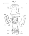
- FIG. 17 is an exploded perspective view showing the component parts of the side actuation mechanism of the third embodiment.
- FIG. 18 is an exploded perspective view showing the lower housing, mouthpiece, closure and revolvable element of the third embodiment.
- FIG. 19 is a part-sectional side view showing the third embodiment with the closure in the closed position and the revolvable element in the restricting position such that dispensing of the dose of the medicament formulation is prevented.
- FIG. 20 is a part-sectional side view showing the third embodiment with the closure in the open position and the revolvable element in the non-restricting position such that dispensing of the dose of the medicament formulation is not prevented.
- FIGS. 1 to 6 are views showing a hand-held, hand-operable, breath-coordinated pMDI 70 according to a first embodiment of the present invention for use by a patient 71 .
- the pMDI 70 comprises a container unit 14 and a housing 1 in which the container unit 14 is slidable along its longitudinal axis L-L.
- the housing 1 is generally tubular and of L-shape having an axial section 1 a and a transverse section 1 b configured as a mouthpiece 3 .
- the transverse section 1 b is configured as a nasal nozzle for insertion into the patient's nostril 75 .
- the housing 1 may be moulded from a plastics material, for example by injection moulding. Conveniently, the housing is of polypropylene. In the use orientation of the pMDI 70 shown in FIGS. 2 to 6 , the housing 1 has an upper end 4 a in the axial section 1 a , through which the container unit 14 is insertable into the housing 1 , and a lower open end 4 b in the mouthpiece 3 .
- the pMDI 70 further comprises a cap 20 which covers the upper end of the container unit 14 and is also reversibly slidable into the housing 1 . Downward application of pressure by the user 71 causes the cap 20 to push the container unit 14 into the housing 1 , provided that a closure 5 is in the open position, as depicted in FIG. 6 .
- the container unit 14 comprises a pressurised aerosol canister 14 a having a metering valve 50 at its leading or business end and a dose counter module 14 b mounted on the leading (valve) end of the canister 14 a .
- Metering valves are commercially available from manufacturers well known in the aerosol industry, for example, from Valois, France (e.g. DF10, DF30, DF60), Bespak plc, UK (e.g. BK300, BK356) and 3M-Neotechnic Ltd, UK (e.g. SpraymiserTM).
- An exemplary metering valve is disclosed in U.S. Pat. Nos. 6,170,717, 6,315,173 and 6,318,603.
- the metering chamber (not shown) of the metering valve 50 may be coated with a fluorinated polymer coating, for instance by cold plasma polymerisation, as detailed in US-A-2003/0101993.
- the canister 14 a contains a pressurised medicinal aerosol formulation, as known in the art and mentioned briefly hereinabove.
- the canister 14 a may be made of aluminium and may have its inner surfaces coated with a fluorocarbon polymer, optionally blended with a non-fluorocarbon polymer, for example a blend of polytetrafluoroethylene (PTFE) and polyethersulphone (PES).
- PTFE polytetrafluoroethylene
- PES polyethersulphone
- the dose counter module 14 b is as described in PCT Patent Application No. WO-A-2004/001664 and its US equivalent US-A-2006/0096594.
- the dose counter module 14 b is fixably secured on the valve assembly end of the canister 14 a and includes a display which denotes the number of metered doses of the medicament formulation remaining in the canister 14 a .
- the display of the dose counter module 14 b is visible to the patient through a window provided in the housing 1 .
- the display of the dose counter module 14 b and the housing window are not shown in the first embodiment. However, they are illustrated in FIGS. 7 to 13 showing a second embodiment, the display being labelled 115 and the window labelled 116 .
- a hollow stem block 18 protrudes vertically from an internal basal surface of the housing 1 along axis L-L.
- the stem block 18 receives a valve stem 14 c of the metering valve assembly 50 when the container unit 14 is received in the housing 1 in a “rest position”.
- the stem block 18 has an internal passageway with an inlet end 18 a for receiving the valve stem 14 c and an outlet end 18 b , which faces the mouthpiece 3 .
- the stem block 18 holds the valve stem 14 c stationary whereby depression of the cap 20 and thereby the container unit 14 from its rest position further into the housing to an “actuated position” causes the valve stem 14 c to be displaced from an extended position to a depressed position relative to the canister 14 a .
- This displacement causes a metered dose of the aerosol formulation to be dispensed from the canister 14 a , through the outlet end 18 b of the stem block 18 and out of the mouthpiece 3 , as indicated in FIG. 6 .
- a patient 71 in need of a metered dose of the medicinal aerosol formulation places his or her lips on the mouthpiece 3 of the housing 1 and then concurrently inhales and, with their finger(s) 73 , depresses the container unit 14 into the housing 1 by applying downward pressure to the cap 20 (arrow F, FIG. 6 ) to cause the metering valve 50 to release a metered dose of the medicinal formulation from the container unit 14 for entrainment in the inspiratory airflow produced by the patient for deposition in their lungs.
- the patient 71 has to coordinate their inhalation with the actuation of the pMDI 70 , hence the term “breath-coordinated inhaler”.
- the depression of the container unit 14 into the housing 1 also results in the dose counter module 14 b recording the release of the dose and showing the number of metered doses left in the canister 14 a , as described in WO-A-2004/001664 supra.
- the pMDI 70 comprises a revolvable element 6 which is revolvably mounted in a slot 29 in a base 25 of the housing 1 and further which is associated with a closure 5 for closing the mouthpiece 3 when the pMDI 70 is not in use.
- the closure 5 may be moulded, for example by injection moulding, from a plastics material, for example polypropylene.
- the closure 5 and the revolvable element 6 may form a single component part of the pMDI 70 , e.g. a single moulded part.
- the revolvable element 6 revolves around a fixed axis X which passes through the body of the revolvable element 6 and through the housing 1 .
- the fixed axis X is perpendicular to the longitudinal axis L-L.
- the fixed axis X takes the form of the axis of an axle 21 around, or on, which the revolvable element 6 revolves.
- the revolvable element 6 has a generally ‘P’-shaped body and the fixed axis X passes through the generally semicircular part 23 of the ‘P’-shaped body.
- the generally semicircular part 23 of the ‘P’-shaped revolvable element 6 faces outwards away from the housing 1 .
- the generally semicircular part 23 of the ‘P’-shaped revolvable element 6 faces and protrudes inwards into the housing 1 .
- the revolvable element 6 is associated with the closure 5 by means of a hinge 8 therebetween, in this embodiment a so-called “living hinge”.
- a hinge allows the closure 5 to precisely or closely match the dimensions of the mouthpiece 3 whilst remaining operably connected to the revolvable element 6 .
- the closure 5 can swing downwards on the hinge 8 so as to uncover the mouthpiece 3 when the closure is being moved to the open position. To uncover the mouthpiece 3 , the user simply pulls the closure 5 downwards and away from the mouthpiece 3 with sufficient force to overcome a snap-fit connection therebetween (not shown).
- the hinge 8 also allows the angle between the closure 5 and the revolvable element 6 to change relative to each other whilst the revolvable element 6 revolves around the fixed axis X. Therefore, when moving the closure 5 to the open position, once the closure 5 has cleared the mouthpiece 3 , the closure 5 may be pushed back beneath the mouthpiece 3 , thereby causing the revolvable element 6 to revolve around its axis X, and secured to the base 25 of the housing 1 , e.g. by means of a snap-fit or interference fit connection (not shown). When secured in this position the closure 5 covers the slot 29 and the revolvable element 6 , the generally semicircular part 23 of which faces outwardly away from the housing 1 . More particularly, the generally semicircular part 23 protrudes into the inner volume 27 of the closure 5 .
- the closure 5 when the closure 5 is in the open position as shown in FIG. 5 , covering the revolvable element 6 and secured to the base 25 of the housing 1 , it may form a seal between the closure 5 and the housing 1 and may, therefore, reduce airflow out of the slot 29 in the housing 1 , in which the revolvable element 6 is revolvably mounted, during inhalation of a dose of the medicament formulation.
- By reducing the airflow through slot 29 the normal top to bottom airflow profile of the inhaler device during inhalation is less disrupted than would otherwise be the case.
- the association of the closure 5 with the revolvable element 6 through the hinge 8 causes the revolvable element 6 to revolve around the fixed axis X.
- the revolvable element 6 defines a restricting member 7 which restricts movement of the container unit 14 in the housing 1 when the closure 5 is in the closed position whereby inadvertent dispensing from the canister 14 a and concomitant counting by the dose counter module 14 b is prevented.
- the arcuate surface of the generally semicircular part 23 of the ‘P’-shape defines a restricting surface 7 a of the restricting member 7 .
- the revolvable element 6 revolves around the fixed axis X in a counter-clockwise direction, when viewed as shown in FIGS. 2 to 6 and the restricting surface 7 a is caused to move from facing outwards, away from the housing 1 , to facing inwards into the housing 1 .
- the restricting surface 7 a When inwardly facing, the restricting surface 7 a is in a position to restrict relative movement between the container unit 14 and the housing 1 through abutment of the container unit 14 with the restricting surface 7 a , more particularly abutment of the dose counter module 14 b with the restricting surface 7 a , and thus prevent inadvertent dispensing of a dose of the medicament formulation and counting by the dose counter module 14 b when the pMDI 70 is not in use.
- Such inadvertent dispensing/counting might occur, for example, during shipping of the pMDI 70 from the manufacturer to the distributor, or when the pMDI 70 is in a patient's pocket or handbag, or even as a result of a person fiddling/playing with the pMDI 70 . Wastage of the medicinal formulation is therefore reduced.
- the revolvable element 6 and cap 20 may be moulded from a plastics material, for example by injection moulding. Conveniently, these elements are of polypropylene.
- the restricting surface 7 a abuts against, or is located in close proximity to, the lead ending of the counter module 14 b when the closure 5 is in the closed position.
- the association of the closure 5 with the revolvable element 6 through the hinge 8 causes the revolvable element 6 to revolve around the fixed axis X in the direction opposite to that revolved when the closure 5 is moved from the open position to the closed position as described above. Therefore, as the closure 5 is moved form the closed position to the open position, the revolvable element 6 revolves around the fixed axis X and the restricting surface 7 a is caused to move from facing inwards into the housing, to facing outwards, away from the housing 1 .
- the restricting surface 7 a When outwardly facing, the restricting surface 7 a , just like all the other surfaces of the revolvable element 6 , is not in a position to restrict relative movement between the container unit 14 and the housing 1 and thus the user is able to release a dose of the medicinal formulation by depressing the cap 20 when the closure 5 is in the open position. Moreover, the dose counter module 14 b records the dose release.
- FIGS. 7 to 13 A second hand-held, hand operable, breath-coordinated pMDI 170 of the invention is shown in FIGS. 7 to 13 , only the features of which not exhibited by the first pMDI 70 being described in any detail hereinbelow.
- the revolvable element 106 has two, spaced apart, parallel ‘P’-shaped members, 106 a and 106 b .
- the revolvable element 106 has a bridging member 106 c which connects the two ‘P’-shaped members 106 a and 106 b .
- Each ‘P’-shaped member 106 a , 106 b presents a restricting surface 107 a which functions in the same way as in the first embodiment of FIGS. 1 to 6 . More particularly, the two restricting surfaces 107 a are positioned on either side of the stem block 118 when the closure 105 is in the closed position (see FIG.
- FIGS. 14 to 20 A third hand-held, hand operable, breath-coordinated pMDI 270 of the invention is shown in FIGS. 14 to 20 , only the features of which not exhibited by the first or second pMDIs 70 ; 170 being described in any detail hereinbelow.
- Dispensing of the dose of the medicament formulation is achieved by the user depressing side actuation levers 250 a, b while holding the pMDI 270 with the closure 205 in the open position.
- the housing comprises two separate component parts, an upper housing 201 a and a lower housing 201 b assemblable by a bayonet fitting, infra.
- the lower housing 201 b receives dose counter module 214 b , which is attached to the leading edge of canister 214 a , incorporates stem block 218 and axle 221 for securing the revolvable element 206 .
- Mouthpiece 203 is not integrally formed with the lower housing 201 b and instead forms a separate component part.
- the upper housing part 201 a comprises a hollow, shell-like upper body, of generally inverted T-shape, which presents lateral apertures 249 a, b for receipt of the side actuation levers 250 a, b respectively.
- the upper housing part 201 a further comprises a chassis 289 which provides pivot elements 251 a, b for engagement with pivot elements 276 a, b of the levers 250 a, b for pivotal movement thereof in the lateral apertures 249 a, b between a rest position ( FIGS. 14-16 ) and an inward, actuated position (not shown).
- the chassis 289 includes a pair of arms 290 a, b at its lower end which form the male part of a bayonet fitting which connects the upper and lower housing parts 201 a, b to form the housing 201 .
- the female part of the bayonet fitting is provided in the lower housing part 201 b (not shown).
- FIG. 17 shows a loading member 261 which translates the inward depression of the side actuation levers 250 a, b into relative movement between the container unit 214 and the housing 201 , and thereby dispensing of a dose of the medicament formulation.
- the loading member 261 is fitted over the container unit 214 and pivotal movement of the levers 250 a, b between their rest and actuated positions provides for actuation of the canister 214 a by engagement with the loading member 261 .
- the loading member 261 comprises a sleeve 271 which is a close fit with the outer peripheral wall of the canister 214 a , an end section 273 at one, the upper, end of the sleeve 271 , here which spans the sleeve 271 , which engages the base of the canister 214 a , and a loading section 275 which presents a flange, at the other, lower end of the sleeve 271 , which is engaged by the actuating levers 250 a, b to load the canister 214 a.
- FIG. 17 shows that the levers 250 a, b are hollow, shell-like members, each presenting a pair of loading arms 279 which, in use, straddle the container unit 214 to act on the loading section 275 of the loading member 261 on opposing sides of the container unit 214 .
- the user manually puts the pMDI 270 in the “mouthpiece open” configuration shown in FIG. 15 , then takes the mouthpiece 203 in his/her lips, and, in co-ordination with an inhalation breath, actuates the inhaler by depressing the actuation levers 250 a, b with one or more digits of the hand holding the pMDI 270 .
- Depression of the levers 250 a, b causes inward rotation thereof, such that the loading arms 279 of the levers 250 a, b drive the loading section 275 of the loading member 261 , and hence the loading member 261 , downwardly, which downward movement of the loading member 261 drives the container unit 214 downwardly in relation to the valve stem (not shown) of the canister 214 a which is held stationary by the stem block 218 .
- the loading arms 279 operate on the loading section 275 to push the loading member 261 downwardly.
- This downward movement of the container unit 214 in relation to the stationary valve stem actuates the canister 214 a to deliver a metered spray of the medicament formulation from the valve stem into and through the mouthpiece 203 .
- the resulting downward movement of the container unit 214 in the housing 201 not only results in the metering valve being opened, for dispensement of a metered dose of medicament, but also the display of the dose counter module 214 b being advanced, as detailed in WO-A-2004/001664 supra.
- the pMDI 270 is reset by the return spring in the metering valve ready for subsequent actuation.
- the pMDI 270 is removed from the user's mouth and the mouthpiece 203 closed by the closure 205 , ready for subsequent actuation.
- the closure 205 and revolvable element 206 are formed as separate sub-components which are assemblable into a unitary component through any suitable connection, e.g. an interference fit or a snap-fit.
- the revolvable element 206 is integrally formed with the hinge 208 .
- the closure 205 and revolvable element 206 are of a plastics material, more conveniently moulded plastics parts in which case the hinge 208 is a living hinge.
- the levers 250 a, b are integrally formed with the chassis 289 , e.g. as a one-piece moulding.
- the levers 250 a, b are linked to the chassis 289 through living hinges to provide the required pivotal movement of the levers 250 a, b.
- the two restricting surfaces 207 a of the two generally ‘P’-shaped members 206 a and 206 b do not restrict relative movement between the container unit 214 and the housing 201 , and thereby do not prevent dispensing of a dose of the medicament formulation.
- the closure 105 ; 205 when the closure 105 ; 205 is in its open position secured to the base 125 ; 225 of the housing 101 ; 201 , the closure 105 ; 205 not only encloses the revolvable element 106 ; 206 and associated slots 129 ; 229 , but also acts as a stand on which the pMDI 170 ; 270 can be stood upright in its use orientation.
- the exemplary inhalers of the invention are breath-coordinated pMDIs, in distinction from breath-operated pMDIs.
- breath-operated pMDIs An example of a breath-operated pMDI can be seen in U.S. Pat. No. 5,447,150.
- the exemplary inhalers of the invention may be used in conjunction with an overwrap package for storing and containing the inhaler, including those described in U.S. Pat. Nos. 6,390,291, 6,119,853, 6,179,118, 6,679,374, 6,315,112, and 6,352,152.
- the medicament contained in the container unit of the present invention may be for the treatment of mild, moderate or severe acute or chronic symptoms or for prophylactic treatment.
- the medicament is suitable for treating respiratory diseases, e.g. asthma, chronic obstructive pulmonary disease (COPD), although may be for other therapeutic indications, e.g. treating rhinitis.
- respiratory diseases e.g. asthma, chronic obstructive pulmonary disease (COPD)
- COPD chronic obstructive pulmonary disease
- Appropriate therapeutic agents or medicaments may thus be selected from, for example:
- analgesics e.g., codeine, dihydromorphine, ergotamine, fentanyl or morphine;
- anginal preparations e.g., diltiazem
- antiallergics e.g., cromoglycate (e.g. as the sodium salt), ketotifen or nedocromil (e.g. as the sodium salt);
- antiinfectives e.g., cephalosporins, penicillins, streptomycin, sulphonamides, tetracyclines and pentamidine;
- antihistamines e.g., methapyrilene
- H1 antagonists e.g., amelexanox, astemizole, azatadine, azelastine, acrivastine, brompheniramine, cetirizine, levocetirizine, efletirizine, chlorpheniramine, clemastine, cyclizine, carebastine, cyproheptadine, carbinoxamine, descarboethoxyloratadine, doxylamine, dimethindene, ebastine, epinastine, efletirizine, fexofenadine, hydroxyzine, ketotifen, loratadine, levocabastine, mizolastine, mequitazine, mianserin, noberastine, meclizine, norastemizole, olopatadine, picumast, pyrilamine, promethazine, terfenadine, tripelennamine, temelast
- H3 antagonists e.g. those compounds disclosed in WO-A-04035556 and in WO-A-06045416;
- H4 antagonists e.g. the compounds disclosed in Jablonowski et al., J. Med. Chem. 46:3957-3960 (2003);
- anti-inflammatories e.g., methyl prednisolone, prednisolone, dexamethasone, fluticasone propionate, 6 ⁇ ,9 ⁇ -difluoro-11 ⁇ -hydroxy-16 ⁇ -methyl-17 ⁇ -[(4-methyl-1,3-thiazole-5-carbonyl)oxy]-3-oxo-androsta-1,4-diene-17 ⁇ -carbothioic acid S-fluoromethyl ester, 6 ⁇ ,9 ⁇ -difluoro-17 ⁇ -[(2-furanylcarbonyl)oxy]-11 ⁇ -hydroxy-16 ⁇ -methyl-3-oxo-androsta-1,4-diene-17 ⁇ -carbothioic acid S-fluoromethyl ester (fluticasone furoate), 6 ⁇ ,9 ⁇ -difluoro-11 ⁇ -hydroxy-16 ⁇ -methyl-3-oxo-17 ⁇ -propionyloxy-androsta-1,4-diene-17 ⁇ -carbothioic acid S-(2-oxo-te
- antitussives e.g., noscapine
- bronchodilators e.g., ⁇ 2 -adrenoreceptor agonists including salmeterol (which may be a racemate or a single enantiomer such as the R-enantiomer), salbutamol (which may be a racemate or a single enantiomer such as the R-enantiomer), formoterol (which may be a racemate or a single duastereomer such as the R,R-diastereomer), salmefamol, fenoterol carmoterol, etanterol, naminterol, clenbuterol, pirbuterol, flerbuterol, reproterol, bambuterol, indacaterol, terbutaline and salts thereof, for example the xinafoate (1-hydroxy-2-naphthalenecarboxylate) salt of salmeterol, the sulphate salt or free base of salbutamol or the fumarate salt of formot
- ⁇ 2-adrenoreceptor agonists include those described in WO 02/066422, WO 02/070490, WO 02/076933, WO 03/024439, WO 03/072539, WO 03/091204, WO 04/016578, WO 2004/022547, WO 2004/037807, WO 2004/037773, WO 2004/037768, WO 2004/039762, WO 2004/039766, WO01/42193 and WO03/042160;
- ⁇ 2-adrenoreceptor agonists examples include:
- the ⁇ 2 -adrenoreceptor agonist may be in the form of a salt formed with a pharmaceutically acceptable acid selected from sulphuric, hydrochloric, fumaric, hydroxynaphthoic (for example 1- or 3-hydroxy-2-naphthoic), cinnamic, substituted cinnamic, triphenylacetic, sulphamic, sulphanilic, naphthaleneacrylic, benzoic, 4-methoxybenzoic, 2- or 4-hydroxybenzoic, 4-chlorobenzoic and 4-phenylbenzoic acid.
- a pharmaceutically acceptable acid selected from sulphuric, hydrochloric, fumaric, hydroxynaphthoic (for example 1- or 3-hydroxy-2-naphthoic), cinnamic, substituted cinnamic, triphenylacetic, sulphamic, sulphanilic, naphthaleneacrylic, benzoic, 4-
- PDE4 inhibitors e.g. cis-4-cyano-4-(3-cyclopentyloxy-4-methoxyphenyl)cyclohexan-1-carboxylic acid, 2-carbomethoxy-4-cyano-4-(3-cyclopropylmethoxy-4-difluoromethoxyphenyl)cyclohexan-1-one, cis-[4-cyano-4-(3-cyclopropylmethoxy-4-difluoromethoxyphenyl)cyclohexan-1-ol] and cis-4-cyano-4-[3-(cyclopentyloxy)-4-methoxyphenyl]cyclohexane-1-carboxylic acid (also known as cilomilast) and its salts, esters, pro-drugs or physical forms, which is described in U.S. Pat. No. 5,552,438 issued 3 Sep., 1996; this patent and the compounds it discloses are incorporated herein in full by reference;
- PDE4 inhibitors are disclosed in the published international patent application WO04/024728 (Glaxo Group Ltd), WO04/056823 (Glaxo Group Ltd) and WO04/103998 (Glaxo Group Ltd);
- leukotriene antagonists e.g. montelukast, pranlukast and zafirlukast
- iNOS inhibitors e.g. those disclosed in WO-A-9313055, WO-A-9830537, WO-A-0250021, WO-A-9534534 or WO-A-9962875;
- adenosine 2a agonists e.g. 2R,3R,4S,5R-2-[6-Amino-2-(1S-hydroxymethyl-2-phenyl-ethylamino)-purin-9-yl]-5-(2-ethyl-2H-tetrazol-5-yl)-tetrahydro-furan-3,4-diol (e.g. as maleate)]; [ ⁇ 4 integrin inhibitors e.g.
- diuretics e.g., amiloride
- anticholinergics e.g., ipratropium (e.g. as bromide) tiotropium, atropine, oxitropium, revatropate (e.g. as the hydrobromide) or LAS-34273 which is disclosed in WO-A-0104118;
- hormones e.g., cortisone, hydrocortisone or prednisolone
- xanthines e.g., aminophylline, choline theophyllinate, lysine theophyllinate or theophylline
- therapeutic proteins and peptides e.g., insulin or glucagons.
- the medicaments may be used in the form of salts, (e.g., as alkali metal or amine salts or as acid addition salts) or as esters (e.g., lower alkyl esters) or as solvates (e.g., hydrates) to optimise the activity and/or stability of the medicament and/or to minimise the solubility of the medicament in the propellant.
- salts e.g., as alkali metal or amine salts or as acid addition salts
- esters e.g., lower alkyl esters
- solvates e.g., hydrates
- the medicament is an anti-inflammatory compound for the treatment of inflammatory disorders or diseases such as asthma and rhinitis.
- the medicament is formulated in a hydrofluoroalkane propellant, such as HFA-134a or HFA-227 or a combination thereof.
- a hydrofluoroalkane propellant such as HFA-134a or HFA-227 or a combination thereof.
- the medicament is an anti-inflammatory steroid, such as a corticosteroid (for instance fluticasone furoate or fluticasone propionate, mometasone furoate or cyclesonide) or a long acting beta agonist (LABA), such as salmeterol, for example, as the xinafoate salt, or a combination thereof.
- a corticosteroid for instance fluticasone furoate or fluticasone propionate, mometasone furoate or cyclesonide
- LAA long acting beta agonist
- salmeterol for example, as the xinafoate salt, or a combination thereof.
- Preferred medicaments are salmeterol, salmeterol xinafoate, salbutamol, salbutamol sulphate, fluticasone furoate, fluticasone propionate, mometasone furoate, ciclesonide, and beclomethasone dipropionate and salts, esters or solvates thereof.
- NSAIDs e.g. PDE4 inhibitors, leukotriene antagonists, iNOS inhibitors, tryptase and elastase inhibitors, beta-2 integrin antagonists and adenosine 2a agonists.
- the medicaments may be delivered in combinations.
- salbutamol e.g. as the free base of the sulphate salt
- salmeterol e.g. as the xinafoate salt
- an anti-inflammatory steroid such as beclomethasone (e.g. as an ester, preferably dipropionate) or fluticasone furoate or fluticasone propionate.
Abstract
Description
- 3-(4-{[6-({(2R)-2-hydroxy-2-[4-hydroxy-3-(hydroxymethyl)phenyl]ethyl}amino)hexyl]oxy}butyl)benzenesulfonamide;
- 3-(3-{[7-({(2R)-2-hydroxy-2-[4-hydroxy-3-hydroxymethyl)phenyl]ethyl}-amino)heptyl]oxy}propyl)benzenesulfonamide;
- 4-{(1R)-2-[(6-{2-[(2,6-dichlorobenzyl)oxy]ethoxy}hexyl)amino]-1-hydroxyethyl}-2-(hydroxymethyl)phenol;
- 4-{(1R)-2-[(6-{4-[3-(cyclopentylsulfonyl)phenyl]butoxy}hexyl)amino]-1-hydroxyethyl}-2-(hydroxymethyl)phenol;
- N-[2-hydroxyl-5-[(1R)-1-hydroxy-2-[[2-4-[[(2R)-2-hydroxy-2-phenylethyl]amino]phenyl]ethyl]amino]ethyl]phenyl]formamide;
- N-2{2-[4-(3-phenyl-4-methoxyphenyl)aminophenyl]ethyl}-2-hydroxy-2-(8-hydroxy-2(1H)-quinolinon-5-yl)ethylamine; and
- 5-[(R)-2-(2-{4-[4-(2-amino-2-methyl-propoxy)-phenylamino]-phenyl}-ethylamino)-1-hydroxy-ethyl]-8-hydroxy-1H-quinolin-2-one.
Claims (48)
Applications Claiming Priority (3)
| Application Number | Priority Date | Filing Date | Title |
|---|---|---|---|
| GB0518355.3 | 2005-09-08 | ||
| GBGB0518355.3A GB0518355D0 (en) | 2005-09-08 | 2005-09-08 | An inhaler |
| PCT/GB2006/003307 WO2007028992A1 (en) | 2005-09-08 | 2006-09-07 | An inhaler |
Publications (2)
| Publication Number | Publication Date |
|---|---|
| US20090229604A1 US20090229604A1 (en) | 2009-09-17 |
| US8251056B2 true US8251056B2 (en) | 2012-08-28 |
Family
ID=35221141
Family Applications (1)
| Application Number | Title | Priority Date | Filing Date |
|---|---|---|---|
| US12/066,048 Active 2029-02-26 US8251056B2 (en) | 2005-09-08 | 2006-09-07 | Inhaler |
Country Status (14)
| Country | Link |
|---|---|
| US (1) | US8251056B2 (en) |
| EP (1) | EP1922100B1 (en) |
| JP (1) | JP5308157B2 (en) |
| KR (1) | KR101281699B1 (en) |
| CN (1) | CN101304777A (en) |
| AU (1) | AU2006288911A1 (en) |
| BR (1) | BRPI0615653A2 (en) |
| CA (1) | CA2621440A1 (en) |
| ES (1) | ES2397091T3 (en) |
| GB (1) | GB0518355D0 (en) |
| IL (1) | IL189899A0 (en) |
| MX (1) | MX2008003171A (en) |
| NO (1) | NO20081134L (en) |
| WO (1) | WO2007028992A1 (en) |
Cited By (3)
| Publication number | Priority date | Publication date | Assignee | Title |
|---|---|---|---|---|
| US20080105253A1 (en) * | 2004-03-10 | 2008-05-08 | Glaxo Group Limited | Dispensing Device |
| US20210204870A1 (en) * | 2016-02-17 | 2021-07-08 | Adherium (Nz) Limited | Adherence monitor for a medicament inhaler with tethered cap |
| US11944425B2 (en) | 2014-08-28 | 2024-04-02 | Norton (Waterford) Limited | Compliance monitoring module for an inhaler |
Families Citing this family (28)
| Publication number | Priority date | Publication date | Assignee | Title |
|---|---|---|---|---|
| GB0425518D0 (en) | 2004-11-19 | 2004-12-22 | Clinical Designs Ltd | Substance source |
| GB0428204D0 (en) | 2004-12-23 | 2005-01-26 | Clinical Designs Ltd | Medicament container |
| GB0518400D0 (en) | 2005-09-09 | 2005-10-19 | Clinical Designs Ltd | Dispenser |
| GB0518770D0 (en) * | 2005-09-14 | 2005-10-26 | Glaxo Group Ltd | A closure for a dispensing device |
| AU2007287550A1 (en) * | 2006-08-22 | 2008-02-28 | Glaxo Group Limited | Drug dispenser |
| ES2727926T3 (en) | 2006-08-22 | 2019-10-21 | Glaxo Group Ltd | Drug distributor |
| NZ586655A (en) * | 2008-01-23 | 2012-03-30 | Astrazeneca Ab | A medical dispenser with a display which is covered when dispensing action is in progress |
| WO2010075240A1 (en) * | 2008-12-22 | 2010-07-01 | Novartis Ag | Medical device |
| GB0904059D0 (en) | 2009-03-10 | 2009-04-22 | Euro Celtique Sa | Counter |
| GB0904040D0 (en) | 2009-03-10 | 2009-04-22 | Euro Celtique Sa | Counter |
| NZ596564A (en) * | 2009-05-21 | 2012-11-30 | Microdose Therapeutx Inx | Rotary cassette system for dry powder inhaler with blister packs, a vibrating element and a piercing element |
| MX2012008906A (en) * | 2010-02-10 | 2012-08-15 | Astrazeneca Uk Ltd | Process for providing a filled canister for an inhaler. |
| GB201020638D0 (en) * | 2010-12-06 | 2011-01-19 | Liconsa Laboratorios Sa | Inhalator |
| GB201115870D0 (en) * | 2011-09-14 | 2011-10-26 | Astrazeneca Ab | Inhaler |
| GB201118845D0 (en) * | 2011-11-01 | 2011-12-14 | Euro Celtique Sa | Dispenser |
| GB2496684A (en) * | 2011-11-21 | 2013-05-22 | Adi Wallach | Breathing biofeedback device optionally comprising inhalable substance dispenser and breathing feedback methods |
| US10265484B2 (en) | 2012-09-27 | 2019-04-23 | 3M Innovative Properties Company | Dispensing assembly |
| US20160045684A1 (en) * | 2014-08-18 | 2016-02-18 | Nippharma Co., Ltd. | Inhaler For Powdered Medicaments |
| WO2016090152A1 (en) | 2014-12-03 | 2016-06-09 | 623 Medical, Llc | Dispenser |
| GB2548569A (en) * | 2016-03-21 | 2017-09-27 | Univ Cape Town | An assistive device for an inhaler |
| GB201717996D0 (en) * | 2017-10-31 | 2017-12-13 | Portal Medical Ltd | Medicament dispenser device |
| KR102272946B1 (en) | 2019-03-25 | 2021-07-06 | (주)아이쿱 | Asthma inhaler monitoring device and method for assisting in medical counseling based on asthma inhaler usage information |
| WO2020236658A1 (en) * | 2019-05-17 | 2020-11-26 | Impel Neuropharma, Inc. | Single-use nasal delivery device |
| KR102211450B1 (en) | 2019-05-31 | 2021-02-02 | 동의대학교 산학협력단 | Recognize the time of inhalation of the drug inhaler and administer medication |
| USD1015533S1 (en) | 2019-11-07 | 2024-02-20 | 623 Medical, Llc | Vapocoolant device |
| KR102354664B1 (en) | 2020-01-07 | 2022-01-24 | 제이디코스파마 주식회사 | Medicament inhaler |
| KR102420393B1 (en) | 2020-05-28 | 2022-07-13 | 제이디코스파마 주식회사 | Medicament inhaler |
| KR102494694B1 (en) | 2020-11-10 | 2023-02-01 | 권오석 | Medicament inhaler |
Citations (64)
| Publication number | Priority date | Publication date | Assignee | Title |
|---|---|---|---|---|
| EP0075548A2 (en) | 1981-09-21 | 1983-03-30 | Aktiebolaget Draco | Medical aerosol dispensing device |
| US4664107A (en) | 1983-10-28 | 1987-05-12 | Minnesota Mining And Manufacturing Company | Inhalation activatable dispensers |
| US4771769A (en) | 1982-12-20 | 1988-09-20 | Schering Corporation | Hand held metered spray dispenser |
| US4944429A (en) | 1987-08-28 | 1990-07-31 | Schering Corporation | Manually-operable spray dispenser with locking mechanism |
| US4969578A (en) | 1988-05-09 | 1990-11-13 | Bespak Plc | Dispensing apparatus |
| EP0414536A2 (en) | 1989-08-23 | 1991-02-27 | Riker Laboratories, Inc. | Inhaler |
| EP0428380A1 (en) | 1989-11-14 | 1991-05-22 | Riker Laboratories, Inc. | Inhalation device and protective casing |
| US5119806A (en) * | 1987-05-12 | 1992-06-09 | Glaxo Inc. | Inhalation device |
| FR2682305A1 (en) | 1991-10-11 | 1993-04-16 | Valois | Mechanically actuated device for spraying or dispensing a fluid substance |
| GB2263873A (en) | 1992-05-29 | 1993-08-11 | Norton Healthcare Ltd | Medicament dispensing device |
| GB2264238A (en) | 1992-05-29 | 1993-08-25 | Norton Healthcare Ltd | Medicament inhalor device |
| GB2272162A (en) | 1992-11-06 | 1994-05-11 | Paul Richard Yerbury | Dust proof inhaler |
| US5447150A (en) | 1990-12-01 | 1995-09-05 | Norton Healthcare Limited | Medicament dispensing device |
| US5826571A (en) | 1995-06-08 | 1998-10-27 | Innovative Devices, Llc | Device for use with metered dose inhalers (MDIS) |
| WO1998052634A1 (en) | 1997-05-23 | 1998-11-26 | Pa Knowledge Limited | Inhaler mechanism |
| US5860416A (en) | 1996-04-25 | 1999-01-19 | Bespak Plc | Inhalers |
| US5896853A (en) | 1996-04-26 | 1999-04-27 | Bespak Plc | Controlled flow inhalers |
| US5899200A (en) | 1994-10-25 | 1999-05-04 | Bespak Plc | Aerosol dispensing apparatus |
| US6062214A (en) * | 1996-10-30 | 2000-05-16 | Bespak Plc | Inhaler for medicament |
| US6261274B1 (en) | 1997-01-20 | 2001-07-17 | Valois S.A. | Device for dispensing a fluid or a powder at a predetermined distance |
| WO2001070314A1 (en) | 2000-03-18 | 2001-09-27 | Astrazeneca Ab | Inhaler |
| US6302101B1 (en) | 1999-12-14 | 2001-10-16 | Daniel Py | System and method for application of medicament into the nasal passage |
| WO2001087391A2 (en) | 2000-05-17 | 2001-11-22 | Orion Corporation | Inhaler with a dose counter |
| GB2364320A (en) | 2000-07-06 | 2002-01-23 | Bespak Plc | Dispensing apparatus |
| US6354290B1 (en) | 1998-12-11 | 2002-03-12 | Bespak Plc | Inhalation apparatus |
| US6364166B1 (en) | 1997-11-29 | 2002-04-02 | Ing. Erich Pfeiffer Gmbh | Dispenser with manually operable discharge device |
| US20020056449A1 (en) * | 2000-05-09 | 2002-05-16 | Keith Wakefield | Inhalation actuated device |
| WO2002049698A1 (en) | 2000-12-19 | 2002-06-27 | Astrazeneca Ab | A delivery device |
| US20020117513A1 (en) | 2001-02-28 | 2002-08-29 | Michael Helmlinger | Dispenser for media |
| US6484715B1 (en) | 1998-07-14 | 2002-11-26 | Ing. Erich Pfeiffer Gmbh | Media dispenser |
| US20030052196A1 (en) | 2001-09-18 | 2003-03-20 | Ing. Erich Pfeiffer Gmbh | Dispenser for media |
| WO2003026805A1 (en) | 2001-09-21 | 2003-04-03 | Ing. Erich Pfeiffer Gmbh | Dosing device comprising a medium reservoir and corresponding pump device |
| WO2003026804A1 (en) | 2001-09-21 | 2003-04-03 | Ing. Erich Pfeiffer Gmbh | Dosing device with a medium reservoir and a pump device |
| WO2003026803A1 (en) | 2001-09-21 | 2003-04-03 | Ing. Erich Pfeiffer Gmbh | Dosing device with a pump device |
| WO2003029105A1 (en) | 2001-10-04 | 2003-04-10 | Valois Sas | Laterally-actuated fluid dispensing device |
| US20030100867A1 (en) | 2001-11-29 | 2003-05-29 | Karl-Heinz Fuchs | Dosing device |
| WO2003043909A2 (en) | 2001-11-20 | 2003-05-30 | Valois Sas | Lateral actuation spray device |
| US6578741B2 (en) | 2000-10-16 | 2003-06-17 | Ing. Erich Pfeiffer Gmbh | Dispenser and method for discharging media |
| WO2003061843A1 (en) | 2002-01-22 | 2003-07-31 | Valois Sas | Atomisation device with lateral actuation |
| WO2003074189A1 (en) | 2002-03-01 | 2003-09-12 | Glaxo Group Limited | A fluid dispensing device |
| WO2003080161A1 (en) | 2002-03-22 | 2003-10-02 | Clinical Designs Limited | Can fixture |
| US6644305B2 (en) | 2000-04-14 | 2003-11-11 | Trudell Medical International | Nasal inhaler |
| WO2003095007A2 (en) | 2002-05-09 | 2003-11-20 | Glaxo Group Limited | A fluid dispensing device |
| WO2003095006A2 (en) | 2002-05-09 | 2003-11-20 | Glaxo Group Limited | A fluid dispensing device |
| US6701917B2 (en) | 2000-06-23 | 2004-03-09 | Norton Healthcare, Ltd. | Dose counter for medicament inhaler |
| WO2004028608A1 (en) | 2002-09-25 | 2004-04-08 | 3M Innovative Properties Company | Breath-actuated aerosol dispensers |
| US20040069301A1 (en) * | 2001-01-25 | 2004-04-15 | Bacon Raymond John | Dispenser for medicament |
| US6729324B2 (en) | 1995-06-08 | 2004-05-04 | Innovative Devices, Llc. | Inhalation actuated device for use with metered dose inhalers (MDIs) |
| WO2004041339A2 (en) | 2002-11-04 | 2004-05-21 | Cambridge Consultants Limited | Pressurised inhalers |
| WO2004041334A2 (en) | 2002-11-04 | 2004-05-21 | Bang & Olufsen Medicom A/S | Device for dispension |
| GB2398252A (en) | 2003-02-11 | 2004-08-18 | Bespak Plc | Breath actuated inhaler with vane, link, and sliding member |
| WO2004073776A1 (en) | 2003-02-21 | 2004-09-02 | Clinical Designs Limited | Dispenser |
| US6792941B2 (en) | 1998-03-27 | 2004-09-21 | Astrazeneca Ab | Inhalation device |
| WO2004096329A1 (en) | 2003-04-25 | 2004-11-11 | Alfred Von Schuckmann | Dispenser having a protective cap that covers the dispensing opening |
| US20040237961A1 (en) * | 1995-06-08 | 2004-12-02 | Snow John Medlin | Inhalation actuated device for use with metered dose inhalers (MDIs) |
| US20050011515A1 (en) * | 2003-07-14 | 2005-01-20 | Vortran Medical Technology 1, Inc. | Inhaler with breath actuated dose counter |
| WO2005046774A1 (en) | 2003-11-17 | 2005-05-26 | Astrazeneca Ab | Inhaler cap strap |
| WO2005087299A1 (en) | 2004-03-10 | 2005-09-22 | Glaxo Group Limited | A dispensing device |
| WO2005107955A1 (en) | 2004-05-03 | 2005-11-17 | Meadwestvaco Calmar Gmbh | Manually operated dispenser comprising a protective cap |
| WO2005107838A1 (en) | 2004-05-03 | 2005-11-17 | Meadwestvaco Calmar Gmbh | Manually operated dispenser comprising a protective cap |
| WO2005110520A1 (en) | 2004-05-13 | 2005-11-24 | Meadwestvaco Calmar Gmbh | Manually-operated dispenser with protective cap |
| GB2419292A (en) | 2004-10-22 | 2006-04-26 | Graham Walker | Inhaler with hinged cap |
| WO2006087385A1 (en) | 2005-02-21 | 2006-08-24 | Tebro Sa | Fluid product dispensing head |
| WO2006097756A1 (en) | 2005-03-17 | 2006-09-21 | Glaxo Group Limited | Inhalation devices |
-
2005
- 2005-09-08 GB GBGB0518355.3A patent/GB0518355D0/en not_active Ceased
-
2006
- 2006-09-07 CA CA002621440A patent/CA2621440A1/en not_active Abandoned
- 2006-09-07 BR BRPI0615653-3A patent/BRPI0615653A2/en not_active IP Right Cessation
- 2006-09-07 EP EP06779326A patent/EP1922100B1/en active Active
- 2006-09-07 MX MX2008003171A patent/MX2008003171A/en not_active Application Discontinuation
- 2006-09-07 KR KR1020087008508A patent/KR101281699B1/en active IP Right Grant
- 2006-09-07 US US12/066,048 patent/US8251056B2/en active Active
- 2006-09-07 AU AU2006288911A patent/AU2006288911A1/en not_active Abandoned
- 2006-09-07 WO PCT/GB2006/003307 patent/WO2007028992A1/en active Application Filing
- 2006-09-07 JP JP2008529685A patent/JP5308157B2/en not_active Expired - Fee Related
- 2006-09-07 CN CNA2006800416519A patent/CN101304777A/en active Pending
- 2006-09-07 ES ES06779326T patent/ES2397091T3/en active Active
-
2008
- 2008-03-03 IL IL189899A patent/IL189899A0/en unknown
- 2008-03-04 NO NO20081134A patent/NO20081134L/en not_active Application Discontinuation
Patent Citations (69)
| Publication number | Priority date | Publication date | Assignee | Title |
|---|---|---|---|---|
| EP0075548A2 (en) | 1981-09-21 | 1983-03-30 | Aktiebolaget Draco | Medical aerosol dispensing device |
| US4771769A (en) | 1982-12-20 | 1988-09-20 | Schering Corporation | Hand held metered spray dispenser |
| US4860738A (en) | 1982-12-20 | 1989-08-29 | Schering Corporation | Hand held metered spray dispenser |
| US4664107A (en) | 1983-10-28 | 1987-05-12 | Minnesota Mining And Manufacturing Company | Inhalation activatable dispensers |
| US5119806A (en) * | 1987-05-12 | 1992-06-09 | Glaxo Inc. | Inhalation device |
| US4944429A (en) | 1987-08-28 | 1990-07-31 | Schering Corporation | Manually-operable spray dispenser with locking mechanism |
| US4969578A (en) | 1988-05-09 | 1990-11-13 | Bespak Plc | Dispensing apparatus |
| EP0414536A2 (en) | 1989-08-23 | 1991-02-27 | Riker Laboratories, Inc. | Inhaler |
| US5069204A (en) | 1989-08-23 | 1991-12-03 | Riker Laboratories, Inc. | Inhaler |
| EP0428380A1 (en) | 1989-11-14 | 1991-05-22 | Riker Laboratories, Inc. | Inhalation device and protective casing |
| US5447150A (en) | 1990-12-01 | 1995-09-05 | Norton Healthcare Limited | Medicament dispensing device |
| FR2682305A1 (en) | 1991-10-11 | 1993-04-16 | Valois | Mechanically actuated device for spraying or dispensing a fluid substance |
| GB2264238A (en) | 1992-05-29 | 1993-08-25 | Norton Healthcare Ltd | Medicament inhalor device |
| GB2263873A (en) | 1992-05-29 | 1993-08-11 | Norton Healthcare Ltd | Medicament dispensing device |
| GB2272162A (en) | 1992-11-06 | 1994-05-11 | Paul Richard Yerbury | Dust proof inhaler |
| US5899200A (en) | 1994-10-25 | 1999-05-04 | Bespak Plc | Aerosol dispensing apparatus |
| US5826571A (en) | 1995-06-08 | 1998-10-27 | Innovative Devices, Llc | Device for use with metered dose inhalers (MDIS) |
| US20040237961A1 (en) * | 1995-06-08 | 2004-12-02 | Snow John Medlin | Inhalation actuated device for use with metered dose inhalers (MDIs) |
| US6729324B2 (en) | 1995-06-08 | 2004-05-04 | Innovative Devices, Llc. | Inhalation actuated device for use with metered dose inhalers (MDIs) |
| US5860416A (en) | 1996-04-25 | 1999-01-19 | Bespak Plc | Inhalers |
| US5896853A (en) | 1996-04-26 | 1999-04-27 | Bespak Plc | Controlled flow inhalers |
| US6062214A (en) * | 1996-10-30 | 2000-05-16 | Bespak Plc | Inhaler for medicament |
| US6261274B1 (en) | 1997-01-20 | 2001-07-17 | Valois S.A. | Device for dispensing a fluid or a powder at a predetermined distance |
| WO1998052634A1 (en) | 1997-05-23 | 1998-11-26 | Pa Knowledge Limited | Inhaler mechanism |
| US6364166B1 (en) | 1997-11-29 | 2002-04-02 | Ing. Erich Pfeiffer Gmbh | Dispenser with manually operable discharge device |
| EP1066075B1 (en) | 1998-03-27 | 2005-05-04 | AstraZeneca AB | Inhalation device |
| US6792941B2 (en) | 1998-03-27 | 2004-09-21 | Astrazeneca Ab | Inhalation device |
| US6484715B1 (en) | 1998-07-14 | 2002-11-26 | Ing. Erich Pfeiffer Gmbh | Media dispenser |
| US6354290B1 (en) | 1998-12-11 | 2002-03-12 | Bespak Plc | Inhalation apparatus |
| US6302101B1 (en) | 1999-12-14 | 2001-10-16 | Daniel Py | System and method for application of medicament into the nasal passage |
| WO2001070314A1 (en) | 2000-03-18 | 2001-09-27 | Astrazeneca Ab | Inhaler |
| US6644305B2 (en) | 2000-04-14 | 2003-11-11 | Trudell Medical International | Nasal inhaler |
| US20020056449A1 (en) * | 2000-05-09 | 2002-05-16 | Keith Wakefield | Inhalation actuated device |
| US6637432B2 (en) | 2000-05-09 | 2003-10-28 | Iep Pharmaceutical Devices Inc. | Inhalation actuated device |
| WO2001087391A2 (en) | 2000-05-17 | 2001-11-22 | Orion Corporation | Inhaler with a dose counter |
| US6718972B2 (en) | 2000-06-23 | 2004-04-13 | Ivax Corporation | Dose metering system for medicament inhaler |
| US6701917B2 (en) | 2000-06-23 | 2004-03-09 | Norton Healthcare, Ltd. | Dose counter for medicament inhaler |
| GB2364320A (en) | 2000-07-06 | 2002-01-23 | Bespak Plc | Dispensing apparatus |
| US6578741B2 (en) | 2000-10-16 | 2003-06-17 | Ing. Erich Pfeiffer Gmbh | Dispenser and method for discharging media |
| WO2002049698A1 (en) | 2000-12-19 | 2002-06-27 | Astrazeneca Ab | A delivery device |
| US20040069301A1 (en) * | 2001-01-25 | 2004-04-15 | Bacon Raymond John | Dispenser for medicament |
| US20020117513A1 (en) | 2001-02-28 | 2002-08-29 | Michael Helmlinger | Dispenser for media |
| US20030052196A1 (en) | 2001-09-18 | 2003-03-20 | Ing. Erich Pfeiffer Gmbh | Dispenser for media |
| WO2003026805A1 (en) | 2001-09-21 | 2003-04-03 | Ing. Erich Pfeiffer Gmbh | Dosing device comprising a medium reservoir and corresponding pump device |
| WO2003026803A1 (en) | 2001-09-21 | 2003-04-03 | Ing. Erich Pfeiffer Gmbh | Dosing device with a pump device |
| WO2003026804A1 (en) | 2001-09-21 | 2003-04-03 | Ing. Erich Pfeiffer Gmbh | Dosing device with a medium reservoir and a pump device |
| WO2003029105A1 (en) | 2001-10-04 | 2003-04-10 | Valois Sas | Laterally-actuated fluid dispensing device |
| WO2003043909A2 (en) | 2001-11-20 | 2003-05-30 | Valois Sas | Lateral actuation spray device |
| US20030100867A1 (en) | 2001-11-29 | 2003-05-29 | Karl-Heinz Fuchs | Dosing device |
| WO2003061843A1 (en) | 2002-01-22 | 2003-07-31 | Valois Sas | Atomisation device with lateral actuation |
| WO2003074189A1 (en) | 2002-03-01 | 2003-09-12 | Glaxo Group Limited | A fluid dispensing device |
| WO2003080161A1 (en) | 2002-03-22 | 2003-10-02 | Clinical Designs Limited | Can fixture |
| WO2003095007A2 (en) | 2002-05-09 | 2003-11-20 | Glaxo Group Limited | A fluid dispensing device |
| WO2003095006A2 (en) | 2002-05-09 | 2003-11-20 | Glaxo Group Limited | A fluid dispensing device |
| WO2004028608A1 (en) | 2002-09-25 | 2004-04-08 | 3M Innovative Properties Company | Breath-actuated aerosol dispensers |
| WO2004041334A2 (en) | 2002-11-04 | 2004-05-21 | Bang & Olufsen Medicom A/S | Device for dispension |
| WO2004041339A2 (en) | 2002-11-04 | 2004-05-21 | Cambridge Consultants Limited | Pressurised inhalers |
| GB2398252A (en) | 2003-02-11 | 2004-08-18 | Bespak Plc | Breath actuated inhaler with vane, link, and sliding member |
| WO2004073776A1 (en) | 2003-02-21 | 2004-09-02 | Clinical Designs Limited | Dispenser |
| WO2004096329A1 (en) | 2003-04-25 | 2004-11-11 | Alfred Von Schuckmann | Dispenser having a protective cap that covers the dispensing opening |
| US20050011515A1 (en) * | 2003-07-14 | 2005-01-20 | Vortran Medical Technology 1, Inc. | Inhaler with breath actuated dose counter |
| WO2005046774A1 (en) | 2003-11-17 | 2005-05-26 | Astrazeneca Ab | Inhaler cap strap |
| WO2005087299A1 (en) | 2004-03-10 | 2005-09-22 | Glaxo Group Limited | A dispensing device |
| WO2005107955A1 (en) | 2004-05-03 | 2005-11-17 | Meadwestvaco Calmar Gmbh | Manually operated dispenser comprising a protective cap |
| WO2005107838A1 (en) | 2004-05-03 | 2005-11-17 | Meadwestvaco Calmar Gmbh | Manually operated dispenser comprising a protective cap |
| WO2005110520A1 (en) | 2004-05-13 | 2005-11-24 | Meadwestvaco Calmar Gmbh | Manually-operated dispenser with protective cap |
| GB2419292A (en) | 2004-10-22 | 2006-04-26 | Graham Walker | Inhaler with hinged cap |
| WO2006087385A1 (en) | 2005-02-21 | 2006-08-24 | Tebro Sa | Fluid product dispensing head |
| WO2006097756A1 (en) | 2005-03-17 | 2006-09-21 | Glaxo Group Limited | Inhalation devices |
Cited By (6)
| Publication number | Priority date | Publication date | Assignee | Title |
|---|---|---|---|---|
| US20080105253A1 (en) * | 2004-03-10 | 2008-05-08 | Glaxo Group Limited | Dispensing Device |
| US8397714B2 (en) | 2004-03-10 | 2013-03-19 | Glaxo Group Limited | Dispensing device |
| US9327087B2 (en) | 2004-03-10 | 2016-05-03 | Glaxo Group Limited | Dispensing device |
| US11944425B2 (en) | 2014-08-28 | 2024-04-02 | Norton (Waterford) Limited | Compliance monitoring module for an inhaler |
| US20210204870A1 (en) * | 2016-02-17 | 2021-07-08 | Adherium (Nz) Limited | Adherence monitor for a medicament inhaler with tethered cap |
| US11696726B2 (en) * | 2016-02-17 | 2023-07-11 | Adherium (Nz) Limited | Adherence monitor for a medicament inhaler with tethered cap |
Also Published As
| Publication number | Publication date |
|---|---|
| WO2007028992A1 (en) | 2007-03-15 |
| CA2621440A1 (en) | 2007-03-15 |
| EP1922100A1 (en) | 2008-05-21 |
| ES2397091T3 (en) | 2013-03-04 |
| JP2009507540A (en) | 2009-02-26 |
| EP1922100B1 (en) | 2012-11-07 |
| IL189899A0 (en) | 2008-08-07 |
| KR101281699B1 (en) | 2013-07-03 |
| CN101304777A (en) | 2008-11-12 |
| NO20081134L (en) | 2008-04-16 |
| GB0518355D0 (en) | 2005-10-19 |
| JP5308157B2 (en) | 2013-10-09 |
| KR20080044343A (en) | 2008-05-20 |
| AU2006288911A1 (en) | 2007-03-15 |
| MX2008003171A (en) | 2008-03-18 |
| BRPI0615653A2 (en) | 2012-12-18 |
| US20090229604A1 (en) | 2009-09-17 |
Similar Documents
| Publication | Publication Date | Title |
|---|---|---|
| US8251056B2 (en) | Inhaler | |
| JP2009507591A (en) | Lid for dosing device | |
| JP4940127B2 (en) | Dosing device | |
| US9327088B2 (en) | Drug dispenser | |
| US8820318B2 (en) | Drug dispenser | |
| US8636000B2 (en) | Drug dispenser using a catapult arrangement | |
| WO2009103711A1 (en) | Actuation counter | |
| US20080135043A1 (en) | Inhalation Devices | |
| ZA200607135B (en) | A dispensing device | |
| US20080196713A1 (en) | Inhalation Devices | |
| WO2009112539A2 (en) | A closure |
Legal Events
| Date | Code | Title | Description |
|---|---|---|---|
| AS | Assignment |
Owner name: ORIGIN PRODUCT DESIGN LIMITED, UNITED KINGDOM Free format text: ASSIGNMENT OF ASSIGNORS INTEREST;ASSIGNOR:PEARSON, ALLEN JOHN;REEL/FRAME:020648/0363 Effective date: 20061124 Owner name: GLAXO GROUP LIMITED, UNITED KINGDOM Free format text: ASSIGNMENT OF ASSIGNORS INTEREST;ASSIGNOR:RAND, PAUL KENNETH;REEL/FRAME:020648/0261 Effective date: 20061127 Owner name: GLAXO GROUP LIMITED, UNITED KINGDOM Free format text: ASSIGNMENT OF ASSIGNORS INTEREST;ASSIGNOR:ORIGIN PRODUCT DESIGN LIMITED;REEL/FRAME:020648/0411 Effective date: 20061124 |
|
| STCF | Information on status: patent grant |
Free format text: PATENTED CASE |
|
| FPAY | Fee payment |
Year of fee payment: 4 |
|
| MAFP | Maintenance fee payment |
Free format text: PAYMENT OF MAINTENANCE FEE, 8TH YEAR, LARGE ENTITY (ORIGINAL EVENT CODE: M1552); ENTITY STATUS OF PATENT OWNER: LARGE ENTITY Year of fee payment: 8 |
|
| MAFP | Maintenance fee payment |
Free format text: PAYMENT OF MAINTENANCE FEE, 12TH YEAR, LARGE ENTITY (ORIGINAL EVENT CODE: M1553); ENTITY STATUS OF PATENT OWNER: LARGE ENTITY Year of fee payment: 12 |